EP3239432A1 - Système de façade à lamelles et son utilisation - Google Patents
Système de façade à lamelles et son utilisation Download PDFInfo
- Publication number
- EP3239432A1 EP3239432A1 EP16167154.0A EP16167154A EP3239432A1 EP 3239432 A1 EP3239432 A1 EP 3239432A1 EP 16167154 A EP16167154 A EP 16167154A EP 3239432 A1 EP3239432 A1 EP 3239432A1
- Authority
- EP
- European Patent Office
- Prior art keywords
- lamella
- fixation element
- mounting
- facade system
- leg
- Prior art date
- Legal status (The legal status is an assumption and is not a legal conclusion. Google has not performed a legal analysis and makes no representation as to the accuracy of the status listed.)
- Withdrawn
Links
Images


Classifications
-
- E—FIXED CONSTRUCTIONS
- E04—BUILDING
- E04F—FINISHING WORK ON BUILDINGS, e.g. STAIRS, FLOORS
- E04F13/00—Coverings or linings, e.g. for walls or ceilings
- E04F13/07—Coverings or linings, e.g. for walls or ceilings composed of covering or lining elements; Sub-structures therefor; Fastening means therefor
- E04F13/08—Coverings or linings, e.g. for walls or ceilings composed of covering or lining elements; Sub-structures therefor; Fastening means therefor composed of a plurality of similar covering or lining elements
- E04F13/0801—Separate fastening elements
- E04F13/0803—Separate fastening elements with load-supporting elongated furring elements between wall and covering elements
- E04F13/081—Separate fastening elements with load-supporting elongated furring elements between wall and covering elements with additional fastening elements between furring elements and covering elements
- E04F13/0816—Separate fastening elements with load-supporting elongated furring elements between wall and covering elements with additional fastening elements between furring elements and covering elements the additional fastening elements extending into the back side of the covering elements
- E04F13/0819—Separate fastening elements with load-supporting elongated furring elements between wall and covering elements with additional fastening elements between furring elements and covering elements the additional fastening elements extending into the back side of the covering elements inserted into grooves in the back side of the covering elements
-
- E—FIXED CONSTRUCTIONS
- E04—BUILDING
- E04F—FINISHING WORK ON BUILDINGS, e.g. STAIRS, FLOORS
- E04F10/00—Sunshades, e.g. Florentine blinds or jalousies; Outside screens; Awnings or baldachins
- E04F10/08—Sunshades, e.g. Florentine blinds or jalousies; Outside screens; Awnings or baldachins of a plurality of similar rigid parts, e.g. slabs, lamellae
-
- E—FIXED CONSTRUCTIONS
- E04—BUILDING
- E04F—FINISHING WORK ON BUILDINGS, e.g. STAIRS, FLOORS
- E04F13/00—Coverings or linings, e.g. for walls or ceilings
- E04F13/07—Coverings or linings, e.g. for walls or ceilings composed of covering or lining elements; Sub-structures therefor; Fastening means therefor
- E04F13/08—Coverings or linings, e.g. for walls or ceilings composed of covering or lining elements; Sub-structures therefor; Fastening means therefor composed of a plurality of similar covering or lining elements
- E04F13/0801—Separate fastening elements
- E04F13/0803—Separate fastening elements with load-supporting elongated furring elements between wall and covering elements
- E04F13/081—Separate fastening elements with load-supporting elongated furring elements between wall and covering elements with additional fastening elements between furring elements and covering elements
- E04F13/0814—Separate fastening elements with load-supporting elongated furring elements between wall and covering elements with additional fastening elements between furring elements and covering elements fixed by means of clamping action
-
- E—FIXED CONSTRUCTIONS
- E04—BUILDING
- E04F—FINISHING WORK ON BUILDINGS, e.g. STAIRS, FLOORS
- E04F13/00—Coverings or linings, e.g. for walls or ceilings
- E04F13/07—Coverings or linings, e.g. for walls or ceilings composed of covering or lining elements; Sub-structures therefor; Fastening means therefor
- E04F13/08—Coverings or linings, e.g. for walls or ceilings composed of covering or lining elements; Sub-structures therefor; Fastening means therefor composed of a plurality of similar covering or lining elements
- E04F13/10—Coverings or linings, e.g. for walls or ceilings composed of covering or lining elements; Sub-structures therefor; Fastening means therefor composed of a plurality of similar covering or lining elements of wood or with an outer layer of wood
Definitions
- the present invention relates to a lamella facade system and to use of such lamella facade system.
- Creating such finishing face of a structure e.g. a building, is often a cumbersome and time-consuming process.
- the wood is attached directly to the structure by screws or similar. This implies handling long elements and machinery during the actual facade installation process. If a single board or a single wood part gets deteriorated or otherwise damaged, it is extremely expensive to repair such individual part and involves a great risk of damaging the neighbouring parts.
- a lamella facade system comprising:
- the first side of the fixation element may comprise at least a first projecting leg projecting from the body of the fixation element, the first projecting leg being configured to connect with the attachment means of the metal mounting element.
- an end part of the projection leg may comprise an area of increased thickness.
- attachment means of the metal mounting element may be a separate part affixed to the metal mounting element.
- the attachment means may comprise two projecting attachment arms for engaging with two projecting legs of the fixation element.
- the attachment means may be a number of slots arranged in the interface side, the slots being configured to receive a projecting leg of the fixation element.
- end part of the leg and the slot of the attachment means may constitute a snap-lock arrangement.
- the first side of the fixation element may comprise a second projecting leg having an end part, the end part of the second projecting leg being in a substantially perpendicular position configured to be lockingly engaged with the attachment means of the metal mounting element.
- fixation means may extend substantially along the full length of the longitudinal extension of the non-metal lamella.
- the lamella may be made of wood, wood fibre composites, glass or composites such as compact rock or compact marble.
- a longitudinal extension of the lamella may be different from a length of the fixation element.
- the fixation element may be made of metal.
- the longitudinal extension of the lamella may be more than 5 mm longer than the longitudinal extension of the fixation element.
- the longitudinal extension of the lamella may be longer than the longitudinal extension of the fixation element by 10-100 mm or more.
- fixation element may be 890-990 mm and the lamella may be 990-1010 mm.
- the metal mounting element may have a surface, the surface being treated e.g. by eloxation, anodization or painted.
- end part of the first leg of the fixation element and the connecting part of the mounting element may be arranged to be lockingly engaged substantially without touching each other during mounting of the fixation element when inserting the end part of the first leg from a position in which the first leg, and thereby the fixation element as a whole, is tilted by more than 5° and less than 80° from perpendicular to the mounting element.
- Both the first projecting leg and the second projecting leg may comprise an end part having an increased thickness.
- fixation element may comprise at least one alignment projection extending from the side of the body opposite the side from which the at least one projecting leg extends.
- the alignment projection may be configured to support the lamella.
- the alignment projection may be arranged so as to project into a groove in the lamella.
- the alignment projection may be arranged so as to abut a part of an outer surface of the lamella.
- first projecting leg may have a first extension and the second projecting leg may have a second extension, the first and second extensions being 5-100 mm, more preferred 7.5-75 mm, or even more preferred 10-50 mm.
- the legs may extend approximately 15 mm from the body.
- first and second projecting legs may be identical.
- the extensions of the first and second projecting legs may be different from each other.
- Both the first and the second projecting legs may comprise an end part of increased thickness.
- the first projecting leg and the second projecting leg of the fixation member may be flexible in such way that the distance between the first and second projecting legs may be increased or decreased during mounting of the fixation element with the mounting element.
- the end parts and thereby the fixation element may be lockingly engaged as a snap-lock function.
- the second leg and/or the first leg may be sufficiently flexible in order for the end part having an increased thickness to be pushed past a part on the mounting element in order to regain the initial position, whereby the fixation element and the mounting element are locked together.
- the at least one alignment projection may have an outer surface, the outer surface being substantially even with an outer surface of the lamella.
- the lamella may comprise areas of reduced thickness in order to fit between two projecting legs of the fixation element.
- the lamella may be surface-treated, e.g. by paint or oil.
- the lamella may be acetylate-treated wood, e.g. known under the brand name Accoya.
- the lamella may be affixed to the fixation element by screws.
- the body of the fixation element may comprise a number of apertures.
- the body of the fixation element may comprise apertures, the apertures being 2-20 mm or 3-15 mm or 4-10 mm, or more preferred 5 mm, and a number of the apertures may be elongated apertures.
- a number of the apertures may be elongated apertures.
- the lamella In this way it is possible for the lamella to expand or subtract, i.e. extend or contract differently from the fixation element due to changes in temperature and humidity in the surrounding environment.
- the elongated apertures may have a longitudinal extension of 7.5-50 mm or 10-40 mm or 12.5-30 mm, or more preferred 15-20 mm.
- the lamella facade system may comprise a number of fixation parts.
- fixation element to a mounting element in a controlled manner, i.e. either to allow for movement of the fixation element relative to the mounting element in a perpendicular direction along the longitudinal axis of the fixation element, or to fix the fixation element relative to the mounting element in a perpendicular direction along the longitudinal axis of the fixation element.
- a point with substantially no longitudinal movement due to humidity or temperature i.e. a "movement 0-point" and let the movement start from there.
- the movement is typically caused by changes in temperature and humidity. Since the movement is caused by changes in temperature, the fixation part may be said to provide "a fixation point" in relation to thermal changes.
- the lamella facade system may comprise a plurality of mounting metal elements, each being mounted to the face with a distance between them and a plurality of fixation elements supporting a plurality of lamellae.
- the substantial vertical face may be part of a wall of a building or may be part of a vertical beam or post.
- the present invention also relates to use of the lamella facade system as described above for at least partially covering a structure such as a building or a part of a building.
- the present invention also relates to a building comprising a lamella facade system as described above.
- the present invention relates to a method for creating a facade covering a structure with non-metallic lamellae.
- Fig. 1 shows a lamella facade system 1.
- the system is shown comprising five non-metal lamellae 2 and three metal mounting elements 3.
- the mounting elements 3 have a longitudinal axis MA.
- the mounting elements 3 are attached to a support 4, in this case a face 4 of a building.
- the lamellae 2 have a longitudinal axis LA.
- the longitudinal axis MA of the metal mounting element 3 is substantially perpendicular to the longitudinal axis LA of the lamellae 2.
- the lamellae 2 are connected with the metal mounting elements 3 by a fixation element 5 (shown in greater detail below).
- the lamella facade system could comprise a plurality of mounting metal elements, each being mounted to the face with a distance between them and a plurality of fixation elements supporting a plurality of lamellae.
- the extension of the metal mounting elements and the lamellae and fixation elements may be up to 6000 mm or even more.
- Fig. 2 shows the lamella facade system 1 of Fig. 1 in an exploded view.
- Each of the metal mounting elements 3 comprises a mounting side 6 abutting the face 4 of the building.
- the mounting element 3 further comprises an interfacing side 7 opposing the mounting side 6.
- the interfacing side 7 comprises attachment means 8.
- the attachment means on the mounting element 3 is a number of slots or grooves (only a few are numbered with reference numerals). Only one lamella 2 is shown. However, it will be understood that the system may be expanded to comprise an infinite number of elements and lamellae.
- the lamella 2 is attached with the metal mounting element 3 via the fixation element 5 having a longitudinal axis FA and hence a longitudinal extension.
- the fixation element 5 comprises a body 9 having a first side 10 and a second side 11.
- the first side 10 comprises interfacing means i.e. projecting legs 12, 13.
- the interfacing means comprises a first projecting leg 12 and a second projecting leg 13.
- the projecting legs 12, 13 are configured to be connected with the attachment means 8, i.e. the slots or grooves 8 of the interface side 7 of the mounting element 3.
- the second side 11 of the body 9 of the fixation element 5 is configured to support the lamella 2 along the longitudinal axis of the fixation element FA in order to keep the longitudinal axis LA of the lamella 2 in a substantially parallel position.
- the second side 11 of the fixation element 5 comprises a first alignment projection 14 and a second alignment projection 15.
- the alignment projections 14, 15 project from the second side 11 of the body 9 of the fixation element 5.
- the alignment projections 14, 15 are arranged to be inserted into slots 16, 17 in the lamella 2. In this way it is achieved that the lamella 2 is kept in a position which is substantially parallel to the fixation element 5, and in this embodiment furthermore substantially perpendicular to the mounting elements 3.
- the lamella 2 is affixed to the fixation element 5 by means of screws.
- the fixation of a lamella to the fixation element 5 may be carried out in several ways, still allowing for contraction and expansion of the lamella, e.g. by means of speed prongs in a groove in the lamella or an elastic glue.
- the lamella is made of wood but may be made from various kinds of non-metal material, such as wood fibre composites, rock, glass or fibre glass.
- the longitudinal extension of the lamella 2 is different from a length of the fixation element 5. In this way it is achieved that the lamella and the fixation element may expand or contract differently. If the lamella 2 is made of e.g. wood and the fixation element is made of aluminium, their respective elongation due to changes in temperature is different. Furthermore, wood typically expands due to an increase in humidity in the air which aluminium does not, and hence a change in humidity is likely to cause the lamella to increase in length compared to the fixation element.
- the metal mounting element and the fixation element may be made of a number of metals such as aluminium, alloys of aluminium and at least one other metal or stainless steel.
- lock projections 90 are shown in each side of the mounting element 3 extending in a plane substantially parallel to the mounting side 6 of the mounting element 3. The lock projections will be described further in Figs. 8 , 9 and 10 .
- the longitudinal extension of the lamella 2 is more than 5 mm longer than the longitudinal extension of the fixation element.
- the fixation element 5 is 890-990 mm and the lamella 2 is 990-1010 mm.
- the projecting legs extend approximately 15 mm from the body.
- Fig. 3 shows a part of a lamella facade system 1 seen from the side.
- the lamella 2 is connected with the mounting element 3 via the fixation element 5.
- the projecting legs 12, 13 comprise end parts 22, 23 with an increased thickness.
- the end parts 22, 23 having an increased thickness facilitates that the fixation element 5 can be lockingly engaged with the mounting element 3.
- the grooves 8 in the mounting element 3 comprise a projection 24 which the end part 22, 23 need to pass when inserted in the groove 8. In this way, a simple and reliable snap lock function is obtained.
- the mounting process of the fixation element 5 with the mounting element 3 is described below in Fig. 5 .
- Fig. 3 shows that three embodiments of the fixation element 5.
- the attachment of the lamella 2 to the fixation element 5 may be carried out in various ways e.g. using screws or glue (not shown).
- Figs. 4A-4D show different embodiments of the fixation element 5 having the same lamella 2 connected thereto.
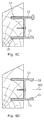
- Fig. 4A shows an end view of an embodiment of the fixation element 5 having a lamella 2 affixed thereto.
- the fixation element comprises one projecting leg 12, the projecting leg having an end part 22 with an increased thickness.
- the increased thickness 22 extends to both sides of the projecting leg 12.
- the slanted top surface 40 provides the possibility of leading e.g. rain water etc. away from the back mounting element 4 and typically the face of the structure.
- the lamella 2 may be arranged to compensate for this tilted position. In this way, the front surface 41 may still be arranged substantially parallel to the mounting element 4 and the face of the structure (seen e.g. in Fig. 3 ).
- the fixation element 5 comprises two alignment projections 16, 17 extending from the body 9 of the fixation element 5.
- the lamella 2 is affixed to the fixation element 5 by a screw 18.
- the screw 18 ensures that the lamella 2 is drawn towards an alignment surface 44 of the body 9.
- the screw(s) 18 may be arranged in elongated apertures.
- the alignment projections 14, 15 are inserted in the alignment slots 16, 17 arranged in the lamella 2.
- the slots 16, 17 may be filled with an elastomer or glue material.
- Fig. 4B shows an embodiment of the fixation element 5.
- the fixation element 5 comprises one alignment projection 14 and one alignment slot 16.
- the alignment projection 14 could be arranged projecting anywhere along the body 9. If the alignment projection 14 is arranged at the middle of the body 9, the screw 18 would be moved accordingly to either the one or the other side of the alignment projection.
- the top surface 40 of the lamella 2 and the front surface 41 are arranged similar to the embodiment shown in Fig. 4A , and hence it will be understood that the fixation element may take various shapes and still maintain the same appearance as the lamella 2.
- Fig. 4C shows an embodiment of the fixation element 5 which is also seen in Figs. 1-3 .
- the fixation element 5 comprises a first projecting leg 12 and a second projection leg 13 as well as a first alignment projection 14 and a second alignment projection 15.
- the end parts 22, 23 of the projecting legs 12, 13 are different from each other.
- the end part 22 has an increased thickness so that the increase in thickness projects both away and towards the end part of the second projecting leg 13.
- the increase in thickness of the second end part 23 of the second projecting leg only projects towards the first projecting leg 12.
- the first projecting leg 12 is similar to those shown in Figs. 1-3 , 4 , 4A and 4B .
- Fig. 4D shows a further embodiment of the fixation element 5.
- the first and the second projection legs 12, 13 of the fixation element 5 comprise end parts having a similar increased thickness.
- the increase in thickness of each of the end parts 22, 23 of the projecting legs is arranged in a way that the increase of the one end part projects towards the other end part, i.e. the end parts have opposing projecting areas.
- the increase in thickness is a projection along the longitudinal axis FA of the fixation element 5.
- this embodiment of the projecting legs of the fixation element 5 may be applied to all embodiments of the fixation element comprising a first and a second projecting leg.
- the attachment means of the metal mounting element i.e. the grooves 8 may in another embodiment be a separate part affixed to the metal mounting element.
- the separate part may comprise two projecting arms configured to receive the legs of the fixation element 5. Such projecting arms is arranged to receive and lockingly engage with projecting legs as shown in both Figs. 4C and 4D .
- the separate part may have a shorter extension along the longitudinal axis LA of the fixation part 5.
- Fig. 4E shows another embodiment of the lamella 2 and the fixation element 5.
- the alignment projections 14, 15 is substantially even with the top surface 40 of the lamella and bottom surface 42 of the lamella 2.
- the slots 16, 17 are merely a section of the lamella 2 having a decreased thickness along the longitudinal axis LA of the lamella.
- the lamella 2 may comprise one slot and a reduced thickness of just the one side, e.g. to create a substantially even top surface 40.
- Fig. 4F shows the flexibility of the projecting legs 12, 13.
- Fig. 4F is highly schematic and the flexibility is typically not more than a few millimetres which is sufficient to achieve a snap-locking effect.
- the second projecting leg 13 is the one to be inserted last.
- the second projecting leg 13 is more likely to be deflecting than the first projecting leg 12. This is due to the fact that the projection 24 of the groove 8 (seen in Fig. 3 ) supports the leg at a point positioned further towards the body 9 of the fixation element.
- the force subjected to the "arm” results in a smaller bending moment of the first projection leg 12 in relation to the second projecting leg 13.
- the second projecting leg 13 is more likely to deflect than the first projecting leg 12 when considering the same thickness of the legs.
- the first projecting leg 12 is similar to those shown in Figs. 1-3 , 4 , 4A, 4B and 4C .
- Fig. 4G and Fig. 4H show further embodiments of the fixation element 5.
- the alignment projections 12, 13 are shorter in relation to the extension of the lamella than the alignment shown in Figs. 1-4F .
- the alignment projections 12, 13 still keep the lamella 2 in position along the longitudinal axis of the fixation element 5.
- the triangular cross section of the alignment projections 12, 13 provide a sloped side of each alignment projection that will assist in carrying water from the first alignment projection 14 towards the second alignment projection 15.
- rain will be deflected by the lamella. However, in some instances the rain may find its way to the fixation element, and in these situations the present embodiment provides an improved water drainage.
- the lamella mounting system may provide for the lamellas to be mounted in a vertical manner, too. Similar to Fig. 4G the embodiment shown in Fig. 4H will provide the same drainage of water. It is shown, that the end parts 22, 23 of the legs may have a more rounded outline than the end parts shown in the other embodiments of the fixation element 5. It will be understood that the end parts shown in Figs. 4G and 4H may also be similar to those of Figs. 4A-4F , also in relation to an embodiment only comprising one leg and one end part (as e.g. shown in Fig. 4A ).
- Fig. 5 shows the mounting process when mounting a lamella 2 affixed to the fixation element 5 as seen comprising a first projecting leg 12 similar to the ones shown in Figs. 1-3 , 4 , 4A, 4B and 4C . Due to the first end part 22 having an increased thickness extending to both sides of projecting leg 12, the end part 22 may not be inserted directly into the groove 8 due to the projections 24. However, when the fixation element 5 and hence the first projection leg 12 is tilted more than 10°, the end part 22 is so configured as to be able to be inserted in the groove 8.
- the fixation element 5 and hence the first projection leg 12 are pivoted and the first end part 22 is in a locked position and hence prevented from being drawn out of the groove again. Pivoting the fixation element 5 even further, the second projecting leg 13 contacts a groove 8, and the increased end part 23 of the second leg 13 only projecting towards the first leg 12 ensures that the second end part still may be inserted in a groove.
- the increased thickness of the second end part 13 ensures that a snap lock function is achieved and that the fixation element 5 as a whole is locked to the mounting element 3.
- fixation element 5 may be mounted in a similar manner, but this embodiment of the fixation element 5 further provides the possibility of mounting it directly along the arrow MD shown in Fig. 4D , i.e. without pivoting around the end part 22 of the first projecting leg 12.
- the metal mounting element 3 is affixed to the face 4 by a bracket.
- the metal mounting element 3 may also be affixed to the face 4 by glue or by a screw e.g. an expansion screw.
- the end part 22 of the first leg 12 of the fixation element 5 and the connecting part of the metal mounting element 3 are arranged to be lockingly engaged substantially without touching each other during mounting of the fixation element 5 when inserting the end part 22 of the first leg 12 from a position in which the first leg 12, and thereby the fixation element 5 as a whole, is tilted by more than 5° and less than 80° from perpendicular to the metal mounting element 3.
- Figs. 6A-6D show further embodiments of the lamella 2 according to the invention. It will be understood by a person skilled in the art that the front surface of the lamella 2 may have various contours and shapes. As shown in Fig. 4A , it is furthermore shown that the top surface 40 and the front surface 41 may have a common area and as such not be separated by a distinct edge or similar.
- Fig. 6D shows a lamella 2 comprising a drip edge 61.
- Fig. 7 shows an embodiment of a section of a fixation element 5, wherein the body of the fixation element comprises a number of apertures 70.
- the fixation element may comprise apertures that are 2-20 mm or 3-15 mm or 4-10 mm, or more preferred 5 mm. It is seen that a number of the apertures are elongated apertures. If the lamella (not shown) to be mounted to the fixation element 5 is less likely to expand, either due to the material of the lamella or the specific conditions of the surroundings in which the lamella facade system is mounted, the apertures 70 may be substantially round. If the lamella is likely to contract or expand in relation to the fixation element 5, the apertures may be elongated.
- the elongated apertures 71 have a longitudinal extension of 7.5-50 mm or 10-40 mm or 12.5-30 mm, or more preferred 15-20 mm. In the embodiment shown in Fig.
- the apertures 70, 71 are shown in the body 9 of the fixation element 5. It will be understood by a person skilled in the art that the apertures may be arranged in either the first or second alignment projection 14, 15 or in two or more of the body 9, the first alignment projection 14 and the second alignment projection 15. Furthermore, it is understood that the screws may be inserted through the lamella and into the fixation element 5. This may be carried out using blind holes in order to hide and/or protect the screw.
- the lamella 2 to expand or subtract, i.e. extend or contract differently and at least along the longitudinal axis LA from the fixation element 5 due to changes in temperature and/or humidity in the surrounding environment.
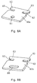
- Fig. 8A and Fig. 8B each show a fixation part (a fixation bracket) 80a and 80b.
- Fig. 8A shows a fixation part 80a having a substantially circular aperture 81.
- the fixation part 80a comprises cut-outs 82 that delimits a part of the fixation part in order to constitute a lock part 83 in each side of the fixation element 80a.
- the lock parts 83 are arranged to engage with lock projections 90 of the mounting element 5 (not shown in Fig. 8A and 8B , described in Figs. 9 and 10 ).
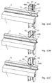
- Figs. 9A-9C show the mounting of the fixation element 80a. It is shown that the fixation part 80a is locked to the mounting element 3 in each side of the mounting element 3 by engaging locking projections 90 extending in a plane substantially parallel to the mounting side of the mounting element 3. Simply by rotating the fixation part 80a ninety degrees, the lock parts 83 of the fixation part 80a are lockingly arranged between the locking projections 90 and the mounting side 6. In this locked position the locking projections 90 are arranged in the cut-outs 82. In this way, the fixation part 80a is fixed in a plane perpendicular to the mounting element 3. Then, when mounting a screw or similar through the aperture 81 (only visible in Fig. 9A ) and into the fixation element 5, the fixation element 5 is fully affixed to the mounting element 3.
- Figs. 10A-10C show the mounting of the fixation element 80b. It is shown that the fixation part 80b is locked to the mounting element 3 in each side of the mounting element 3 by engaging locking projections 90 extending in a plane substantially parallel to the mounting side of the mounting element 3. Simply by rotating the fixation part 80b ninety degrees, the lock parts 83 of the fixation part 80b are lockingly arranged between the locking projections 90 and the mounting side 6. In this way, the fixation part 80b is fixed in a plane perpendicular to the mounting element 3.
- the fixation element 5 when mounting a screw or similar through the elongated aperture 88 and into the fixation element 5, the fixation element 5 is affixed to the mounting element 3, but only in a direction perpendicular to the mounting side of the mounting element 3.
- the elongated aperture 88 allows for movement along the longitudinal axis (LA shown in Fig. 1 ) due to changes in temperature.
- the fixation part 80a provides a 0-point for the longitudinal movement of the fixation element 5. Since most of the longitudinal movement arises from changes in temperature, this 0-point may also be called a thermal fixation point, i.e. a fixed point of the lamella 2 and fixation element 5 despite thermal changes.
- the fixation part 80b provides a fixation in a manner that the fixation element 5 may still be moving along the longitudinal axis LA of the fixation element 5 but in other directions fully affixed to the mounting element 3, i.e. securing the fixation element 5 in the opposite direction of the mounting direction MD shown in Fig. 4D .
- fixation parts 80a and 80b primarily will be affixed to the side of the fixation element 5 comprising the second projecting leg 13. This is due to the substantially flat surface of the second leg 13. However, it will also be possible to mount the fixation parts to the other side, i.e. first leg 12.
- the effect of the fixation parts 80a and 80b are the same no matter whether they are mounted from below, e.g. if mounted to the system shown in Fig. 3 and Fig. 5 or from above as shown in Figs. 9A-C and 10A-C .
- Figs. 9A-C it is shown that the substantially circular aperture 70 is present in the fixation element.
- the 0-point for movement of the lamella 2 in relation to the fixation element 5 is in the same position as the 0-point for the fixation element 5 in relation to the mounting element 3. Due to the fact that the lamella 2 and the fixation element expand and contract differently due to their different materials, it is possible to the control the visual effect of the different expansion and contraction. If the 0-point is placed near the end of a lamella and the fixation element 5, it is achieved that the visual effect is in fact primarily visible in the opposing end.
Priority Applications (7)
| Application Number | Priority Date | Filing Date | Title |
|---|---|---|---|
| EP16167154.0A EP3239432A1 (fr) | 2016-04-26 | 2016-04-26 | Système de façade à lamelles et son utilisation |
| FIEP17721570.4T FI3449067T3 (fi) | 2016-04-26 | 2017-04-25 | Lamellijulkisivujärjestelmä ja sen käyttö |
| US16/096,460 US10640988B2 (en) | 2016-04-26 | 2017-04-25 | Lamella facade system and use thereof |
| ES17721570T ES2952096T3 (es) | 2016-04-26 | 2017-04-25 | Sistema de fachada de lámina y uso del mismo |
| PCT/EP2017/059753 WO2017186694A1 (fr) | 2016-04-26 | 2017-04-25 | Système de façade de lamelle et utilisation correspondante |
| EP17721570.4A EP3449067B1 (fr) | 2016-04-26 | 2017-04-25 | Système de façade à lamelles et son utilisation |
| DK17721570.4T DK3449067T3 (da) | 2016-04-26 | 2017-04-25 | Lamelfrontoverfladesystem |
Applications Claiming Priority (1)
| Application Number | Priority Date | Filing Date | Title |
|---|---|---|---|
| EP16167154.0A EP3239432A1 (fr) | 2016-04-26 | 2016-04-26 | Système de façade à lamelles et son utilisation |
Publications (1)
| Publication Number | Publication Date |
|---|---|
| EP3239432A1 true EP3239432A1 (fr) | 2017-11-01 |
Family
ID=55910126
Family Applications (2)
| Application Number | Title | Priority Date | Filing Date |
|---|---|---|---|
| EP16167154.0A Withdrawn EP3239432A1 (fr) | 2016-04-26 | 2016-04-26 | Système de façade à lamelles et son utilisation |
| EP17721570.4A Active EP3449067B1 (fr) | 2016-04-26 | 2017-04-25 | Système de façade à lamelles et son utilisation |
Family Applications After (1)
| Application Number | Title | Priority Date | Filing Date |
|---|---|---|---|
| EP17721570.4A Active EP3449067B1 (fr) | 2016-04-26 | 2017-04-25 | Système de façade à lamelles et son utilisation |
Country Status (6)
| Country | Link |
|---|---|
| US (1) | US10640988B2 (fr) |
| EP (2) | EP3239432A1 (fr) |
| DK (1) | DK3449067T3 (fr) |
| ES (1) | ES2952096T3 (fr) |
| FI (1) | FI3449067T3 (fr) |
| WO (1) | WO2017186694A1 (fr) |
Cited By (3)
| Publication number | Priority date | Publication date | Assignee | Title |
|---|---|---|---|---|
| IT201900022227A1 (it) * | 2019-11-26 | 2021-05-26 | Univ Degli Studi Di Firenze | Sistema di facciata prefabbricata modulare con rivestimento in materiale ligneo e relativo procedimento di posa in opera |
| RU211861U1 (ru) * | 2022-02-09 | 2022-06-24 | Лушин Максим Георгиевич | Фасадная ламель с т-образным профилем и сотовым заполнением |
| DE102021109220A1 (de) | 2021-04-13 | 2022-10-13 | Ole Öhlschläger | Fassadenabdecksystem für Bauten, insbesondere für Holzrahmenbauten |
Families Citing this family (3)
| Publication number | Priority date | Publication date | Assignee | Title |
|---|---|---|---|---|
| EP3710648A4 (fr) * | 2017-11-17 | 2021-05-05 | Rockwool International A/S | Système de suspension |
| US10927552B2 (en) | 2019-02-15 | 2021-02-23 | Stone Creek Products, LLC | Veneer panel and veneer corner with mounting systems |
| CN109914736A (zh) * | 2019-04-17 | 2019-06-21 | 苏州金螳螂建筑装饰股份有限公司 | 一种薄型金属板装配式龙骨装置 |
Citations (6)
| Publication number | Priority date | Publication date | Assignee | Title |
|---|---|---|---|---|
| JPH0583289U (ja) * | 1992-04-16 | 1993-11-12 | 積水樹脂株式会社 | ブラインドのヘッドレールカバー |
| KR100668113B1 (ko) * | 2005-08-05 | 2007-01-11 | 알루텍 (주) | 탈착식 루버 |
| EP2278090A1 (fr) * | 2009-07-21 | 2011-01-26 | Galimberti S.r.l. | Système de fixation pour une ou plusieurs douves, en particulier pour recouvrir des murs de construction externes et procédé associé pour fixer des douves |
| WO2012035563A1 (fr) * | 2010-09-15 | 2012-03-22 | Mazzetti, Giulio | Structure modulaire pour éléments de surface, élément de surface pour cette structure, et système de couplage pour éléments supportés |
| BE1020429A3 (nl) * | 2011-12-20 | 2013-10-01 | Renson Sunprot Projects Nv | Lamelleninrichting. |
| WO2014068551A1 (fr) * | 2012-10-29 | 2014-05-08 | Hamo Eran | Structures à volets à lamelles agrafées |
Family Cites Families (12)
| Publication number | Priority date | Publication date | Assignee | Title |
|---|---|---|---|---|
| US2042290A (en) * | 1935-06-15 | 1936-05-26 | Herbert J R Barrett | Wall construction |
| US4516373A (en) * | 1981-10-26 | 1985-05-14 | Yoshinori Osawa | Apparatus for tile-setting |
| US4635424A (en) * | 1984-11-26 | 1987-01-13 | Les Enterprises Manuspec Inc. | One-piece fastener for securing a lining element in a removable manner on a carrying surface |
| JP3036914B2 (ja) | 1991-09-20 | 2000-04-24 | 富士通株式会社 | 揺らぎによる遅延時間削減方式 |
| FR2720775B1 (fr) * | 1994-06-01 | 1996-08-09 | Ft 3 R | Dispositif de fixation de plaques de revêtement. |
| JP3529312B2 (ja) * | 1999-12-24 | 2004-05-24 | ニチハ株式会社 | 建築板の留め付け構造 |
| DE102005019977B4 (de) * | 2005-04-27 | 2007-12-27 | Deutsche Steinzeug Cremer & Breuer Ag | Fassadensystem aus keramischen Fassadenplatten zum Einsatz als vorgehängte hinterlüftete Fassade an einer tragenden Bauwerkswand |
| WO2008127207A2 (fr) * | 2007-04-11 | 2008-10-23 | Mehmet Ozkan | Dispositif de montage pour panneau de recouvrement de façade amovible |
| US10145122B2 (en) * | 2014-04-01 | 2018-12-04 | Control Y Desarrollo Empresarial, S.L. | Surface coating and clamp for said coating |
| KR101603905B1 (ko) * | 2015-08-10 | 2016-03-16 | 썬파크 주식회사 | 건축용 부재 지지 장치 |
| AU2016231613A1 (en) * | 2015-09-24 | 2017-04-13 | Woodform Architectural Pty Ltd | A batten fixing system |
| US10550577B2 (en) * | 2017-08-16 | 2020-02-04 | Charbel Tannious Aboukhalil | Face mounting system |
-
2016
- 2016-04-26 EP EP16167154.0A patent/EP3239432A1/fr not_active Withdrawn
-
2017
- 2017-04-25 EP EP17721570.4A patent/EP3449067B1/fr active Active
- 2017-04-25 WO PCT/EP2017/059753 patent/WO2017186694A1/fr active Application Filing
- 2017-04-25 FI FIEP17721570.4T patent/FI3449067T3/fi active
- 2017-04-25 ES ES17721570T patent/ES2952096T3/es active Active
- 2017-04-25 US US16/096,460 patent/US10640988B2/en active Active
- 2017-04-25 DK DK17721570.4T patent/DK3449067T3/da active
Patent Citations (6)
| Publication number | Priority date | Publication date | Assignee | Title |
|---|---|---|---|---|
| JPH0583289U (ja) * | 1992-04-16 | 1993-11-12 | 積水樹脂株式会社 | ブラインドのヘッドレールカバー |
| KR100668113B1 (ko) * | 2005-08-05 | 2007-01-11 | 알루텍 (주) | 탈착식 루버 |
| EP2278090A1 (fr) * | 2009-07-21 | 2011-01-26 | Galimberti S.r.l. | Système de fixation pour une ou plusieurs douves, en particulier pour recouvrir des murs de construction externes et procédé associé pour fixer des douves |
| WO2012035563A1 (fr) * | 2010-09-15 | 2012-03-22 | Mazzetti, Giulio | Structure modulaire pour éléments de surface, élément de surface pour cette structure, et système de couplage pour éléments supportés |
| BE1020429A3 (nl) * | 2011-12-20 | 2013-10-01 | Renson Sunprot Projects Nv | Lamelleninrichting. |
| WO2014068551A1 (fr) * | 2012-10-29 | 2014-05-08 | Hamo Eran | Structures à volets à lamelles agrafées |
Cited By (4)
| Publication number | Priority date | Publication date | Assignee | Title |
|---|---|---|---|---|
| IT201900022227A1 (it) * | 2019-11-26 | 2021-05-26 | Univ Degli Studi Di Firenze | Sistema di facciata prefabbricata modulare con rivestimento in materiale ligneo e relativo procedimento di posa in opera |
| DE102021109220A1 (de) | 2021-04-13 | 2022-10-13 | Ole Öhlschläger | Fassadenabdecksystem für Bauten, insbesondere für Holzrahmenbauten |
| RU211861U1 (ru) * | 2022-02-09 | 2022-06-24 | Лушин Максим Георгиевич | Фасадная ламель с т-образным профилем и сотовым заполнением |
| RU211862U1 (ru) * | 2022-02-09 | 2022-06-24 | Лушин Максим Георгиевич | Фасадная ламель с u-образным профилем и сотовым заполнением |
Also Published As
| Publication number | Publication date |
|---|---|
| EP3449067A1 (fr) | 2019-03-06 |
| ES2952096T3 (es) | 2023-10-27 |
| EP3449067B1 (fr) | 2023-05-10 |
| US10640988B2 (en) | 2020-05-05 |
| DK3449067T3 (da) | 2023-08-14 |
| FI3449067T3 (fi) | 2023-08-08 |
| US20190119926A1 (en) | 2019-04-25 |
| WO2017186694A1 (fr) | 2017-11-02 |
Similar Documents
| Publication | Publication Date | Title |
|---|---|---|
| EP3239432A1 (fr) | Système de façade à lamelles et son utilisation | |
| EP2167749B1 (fr) | Système de plafond mobile | |
| US20200263426A1 (en) | Carrier for a linear ceiling panel | |
| EP2920379B1 (fr) | Elément de grille de paroi sèche souple pour encadrer des structures de paroi sèche | |
| EP3591131A1 (fr) | Système de plafond | |
| US11549279B2 (en) | Panel systems and components | |
| US20180371762A1 (en) | Self-spacing lap siding product | |
| EP3469166B1 (fr) | Revêtement mural | |
| KR20200127830A (ko) | 무용접 방식으로 트러스를 연결하는 브라켓 | |
| CN112912573B (zh) | 用于墙壁的覆层系统、覆层系统的布置以及安装覆层系统的方法 | |
| WO2017130107A1 (fr) | Attache et système de fixation d'installation d'éléments de revêtement de sol | |
| US20210246656A1 (en) | Self-spacing lap and panel siding | |
| US7806570B2 (en) | Reinforcement for linear indirect lighting fixtures | |
| US20180274242A1 (en) | Parapet Particularly For Stairs, Terraces And The Like | |
| ATE156216T1 (de) | Vorrichtung zur befestigung von deckenwinkeln | |
| US20120256063A1 (en) | Arrangement for positioning suspended profiled elements in dry construction | |
| EP3994317B1 (fr) | Accessoire de fixation de profilé et système de support comprenant un tel accessoire de fixation de profilé pour revêtements, planchers surélevés, plafonds surbaissés ou similaires | |
| JP6118717B2 (ja) | 乗客コンベアの保護板並びにそれを用いる乗客コンベア | |
| RU2813820C1 (ru) | Профиль для монтажа натяжного потолка | |
| RU2565287C1 (ru) | Устройство крепления облицовки стен и потолков (варианты) | |
| EP3994318B1 (fr) | Accessoire de fixation de profils et système de support comprenant un tel accessoire de fixation de profils pour revêtement, planchers surélevés, faux-plafonds ou similaires | |
| EP2775067B1 (fr) | Profilé d' habillage de montant | |
| CN219478250U (zh) | 一种遥控器 | |
| EP4194634A1 (fr) | Unité d'arrimage de dispositif de fixation de plafond suspendu | |
| EP2746478B1 (fr) | Profil souple destiné à recouvrir des ouvertures |
Legal Events
| Date | Code | Title | Description |
|---|---|---|---|
| PUAI | Public reference made under article 153(3) epc to a published international application that has entered the european phase |
Free format text: ORIGINAL CODE: 0009012 |
|
| AK | Designated contracting states |
Kind code of ref document: A1 Designated state(s): AL AT BE BG CH CY CZ DE DK EE ES FI FR GB GR HR HU IE IS IT LI LT LU LV MC MK MT NL NO PL PT RO RS SE SI SK SM TR |
|
| AX | Request for extension of the european patent |
Extension state: BA ME |
|
| STAA | Information on the status of an ep patent application or granted ep patent |
Free format text: STATUS: THE APPLICATION IS DEEMED TO BE WITHDRAWN |
|
| 18D | Application deemed to be withdrawn |
Effective date: 20180503 |