EP3239334A1 - Steel plate having excellent resistance to hydrogen-induced cracking, and steel pipe for line pipe - Google Patents
Steel plate having excellent resistance to hydrogen-induced cracking, and steel pipe for line pipe Download PDFInfo
- Publication number
- EP3239334A1 EP3239334A1 EP15873097.8A EP15873097A EP3239334A1 EP 3239334 A1 EP3239334 A1 EP 3239334A1 EP 15873097 A EP15873097 A EP 15873097A EP 3239334 A1 EP3239334 A1 EP 3239334A1
- Authority
- EP
- European Patent Office
- Prior art keywords
- segregated particle
- steel plate
- particle size
- number density
- slab
- Prior art date
- Legal status (The legal status is an assumption and is not a legal conclusion. Google has not performed a legal analysis and makes no representation as to the accuracy of the status listed.)
- Withdrawn
Links
Images



Classifications
-
- C—CHEMISTRY; METALLURGY
- C22—METALLURGY; FERROUS OR NON-FERROUS ALLOYS; TREATMENT OF ALLOYS OR NON-FERROUS METALS
- C22C—ALLOYS
- C22C38/00—Ferrous alloys, e.g. steel alloys
- C22C38/14—Ferrous alloys, e.g. steel alloys containing titanium or zirconium
-
- C—CHEMISTRY; METALLURGY
- C21—METALLURGY OF IRON
- C21D—MODIFYING THE PHYSICAL STRUCTURE OF FERROUS METALS; GENERAL DEVICES FOR HEAT TREATMENT OF FERROUS OR NON-FERROUS METALS OR ALLOYS; MAKING METAL MALLEABLE, e.g. BY DECARBURISATION OR TEMPERING
- C21D8/00—Modifying the physical properties of ferrous metals or ferrous alloys by deformation combined with, or followed by, heat treatment
- C21D8/02—Modifying the physical properties of ferrous metals or ferrous alloys by deformation combined with, or followed by, heat treatment during manufacturing of plates or strips
- C21D8/0221—Modifying the physical properties of ferrous metals or ferrous alloys by deformation combined with, or followed by, heat treatment during manufacturing of plates or strips characterised by the working steps
-
- C—CHEMISTRY; METALLURGY
- C21—METALLURGY OF IRON
- C21D—MODIFYING THE PHYSICAL STRUCTURE OF FERROUS METALS; GENERAL DEVICES FOR HEAT TREATMENT OF FERROUS OR NON-FERROUS METALS OR ALLOYS; MAKING METAL MALLEABLE, e.g. BY DECARBURISATION OR TEMPERING
- C21D8/00—Modifying the physical properties of ferrous metals or ferrous alloys by deformation combined with, or followed by, heat treatment
- C21D8/02—Modifying the physical properties of ferrous metals or ferrous alloys by deformation combined with, or followed by, heat treatment during manufacturing of plates or strips
- C21D8/0221—Modifying the physical properties of ferrous metals or ferrous alloys by deformation combined with, or followed by, heat treatment during manufacturing of plates or strips characterised by the working steps
- C21D8/0226—Hot rolling
-
- C—CHEMISTRY; METALLURGY
- C21—METALLURGY OF IRON
- C21D—MODIFYING THE PHYSICAL STRUCTURE OF FERROUS METALS; GENERAL DEVICES FOR HEAT TREATMENT OF FERROUS OR NON-FERROUS METALS OR ALLOYS; MAKING METAL MALLEABLE, e.g. BY DECARBURISATION OR TEMPERING
- C21D8/00—Modifying the physical properties of ferrous metals or ferrous alloys by deformation combined with, or followed by, heat treatment
- C21D8/02—Modifying the physical properties of ferrous metals or ferrous alloys by deformation combined with, or followed by, heat treatment during manufacturing of plates or strips
- C21D8/0247—Modifying the physical properties of ferrous metals or ferrous alloys by deformation combined with, or followed by, heat treatment during manufacturing of plates or strips characterised by the heat treatment
- C21D8/0263—Modifying the physical properties of ferrous metals or ferrous alloys by deformation combined with, or followed by, heat treatment during manufacturing of plates or strips characterised by the heat treatment following hot rolling
-
- C—CHEMISTRY; METALLURGY
- C22—METALLURGY; FERROUS OR NON-FERROUS ALLOYS; TREATMENT OF ALLOYS OR NON-FERROUS METALS
- C22C—ALLOYS
- C22C38/00—Ferrous alloys, e.g. steel alloys
- C22C38/001—Ferrous alloys, e.g. steel alloys containing N
-
- C—CHEMISTRY; METALLURGY
- C22—METALLURGY; FERROUS OR NON-FERROUS ALLOYS; TREATMENT OF ALLOYS OR NON-FERROUS METALS
- C22C—ALLOYS
- C22C38/00—Ferrous alloys, e.g. steel alloys
- C22C38/002—Ferrous alloys, e.g. steel alloys containing In, Mg, or other elements not provided for in one single group C22C38/001 - C22C38/60
-
- C—CHEMISTRY; METALLURGY
- C22—METALLURGY; FERROUS OR NON-FERROUS ALLOYS; TREATMENT OF ALLOYS OR NON-FERROUS METALS
- C22C—ALLOYS
- C22C38/00—Ferrous alloys, e.g. steel alloys
- C22C38/005—Ferrous alloys, e.g. steel alloys containing rare earths, i.e. Sc, Y, Lanthanides
-
- C—CHEMISTRY; METALLURGY
- C22—METALLURGY; FERROUS OR NON-FERROUS ALLOYS; TREATMENT OF ALLOYS OR NON-FERROUS METALS
- C22C—ALLOYS
- C22C38/00—Ferrous alloys, e.g. steel alloys
- C22C38/02—Ferrous alloys, e.g. steel alloys containing silicon
-
- C—CHEMISTRY; METALLURGY
- C22—METALLURGY; FERROUS OR NON-FERROUS ALLOYS; TREATMENT OF ALLOYS OR NON-FERROUS METALS
- C22C—ALLOYS
- C22C38/00—Ferrous alloys, e.g. steel alloys
- C22C38/04—Ferrous alloys, e.g. steel alloys containing manganese
-
- C—CHEMISTRY; METALLURGY
- C22—METALLURGY; FERROUS OR NON-FERROUS ALLOYS; TREATMENT OF ALLOYS OR NON-FERROUS METALS
- C22C—ALLOYS
- C22C38/00—Ferrous alloys, e.g. steel alloys
- C22C38/06—Ferrous alloys, e.g. steel alloys containing aluminium
-
- C—CHEMISTRY; METALLURGY
- C22—METALLURGY; FERROUS OR NON-FERROUS ALLOYS; TREATMENT OF ALLOYS OR NON-FERROUS METALS
- C22C—ALLOYS
- C22C38/00—Ferrous alloys, e.g. steel alloys
- C22C38/08—Ferrous alloys, e.g. steel alloys containing nickel
-
- C—CHEMISTRY; METALLURGY
- C22—METALLURGY; FERROUS OR NON-FERROUS ALLOYS; TREATMENT OF ALLOYS OR NON-FERROUS METALS
- C22C—ALLOYS
- C22C38/00—Ferrous alloys, e.g. steel alloys
- C22C38/12—Ferrous alloys, e.g. steel alloys containing tungsten, tantalum, molybdenum, vanadium, or niobium
-
- C—CHEMISTRY; METALLURGY
- C22—METALLURGY; FERROUS OR NON-FERROUS ALLOYS; TREATMENT OF ALLOYS OR NON-FERROUS METALS
- C22C—ALLOYS
- C22C38/00—Ferrous alloys, e.g. steel alloys
- C22C38/16—Ferrous alloys, e.g. steel alloys containing copper
-
- C—CHEMISTRY; METALLURGY
- C22—METALLURGY; FERROUS OR NON-FERROUS ALLOYS; TREATMENT OF ALLOYS OR NON-FERROUS METALS
- C22C—ALLOYS
- C22C38/00—Ferrous alloys, e.g. steel alloys
- C22C38/18—Ferrous alloys, e.g. steel alloys containing chromium
- C22C38/40—Ferrous alloys, e.g. steel alloys containing chromium with nickel
- C22C38/58—Ferrous alloys, e.g. steel alloys containing chromium with nickel with more than 1.5% by weight of manganese
-
- C—CHEMISTRY; METALLURGY
- C21—METALLURGY OF IRON
- C21C—PROCESSING OF PIG-IRON, e.g. REFINING, MANUFACTURE OF WROUGHT-IRON OR STEEL; TREATMENT IN MOLTEN STATE OF FERROUS ALLOYS
- C21C7/00—Treating molten ferrous alloys, e.g. steel, not covered by groups C21C1/00 - C21C5/00
- C21C7/04—Removing impurities by adding a treating agent
- C21C7/064—Dephosphorising; Desulfurising
-
- C—CHEMISTRY; METALLURGY
- C21—METALLURGY OF IRON
- C21D—MODIFYING THE PHYSICAL STRUCTURE OF FERROUS METALS; GENERAL DEVICES FOR HEAT TREATMENT OF FERROUS OR NON-FERROUS METALS OR ALLOYS; MAKING METAL MALLEABLE, e.g. BY DECARBURISATION OR TEMPERING
- C21D2211/00—Microstructure comprising significant phases
- C21D2211/004—Dispersions; Precipitations
-
- C—CHEMISTRY; METALLURGY
- C21—METALLURGY OF IRON
- C21D—MODIFYING THE PHYSICAL STRUCTURE OF FERROUS METALS; GENERAL DEVICES FOR HEAT TREATMENT OF FERROUS OR NON-FERROUS METALS OR ALLOYS; MAKING METAL MALLEABLE, e.g. BY DECARBURISATION OR TEMPERING
- C21D9/00—Heat treatment, e.g. annealing, hardening, quenching or tempering, adapted for particular articles; Furnaces therefor
- C21D9/08—Heat treatment, e.g. annealing, hardening, quenching or tempering, adapted for particular articles; Furnaces therefor for tubular bodies or pipes
Definitions
- the present invention relates to a steel plate and a steel pipe for line pipe that have excellent hydrogen-induced cracking resistance.
- the present invention relates to a steel plate that has excellent hydrogen-induced cracking resistance and is suitable for use in line pipe for transportation and tanks for storage of natural gas and crude oil, and to a steel pipe for line pipe with excellent hydrogen-induced cracking resistance, obtained by using the steel plate.
- HIC Hydrogen-induced cracking
- HIC is also known to have a tendency to occur in segregation zones, including a center segregation and internal cracks of a cast strip, particularly, at an inclusion such as MnS, as a starting point. For this reason, some techniques for enhancing HIC resistance have been proposed.
- Patent Document 1 discloses that a steel material has improved HIC resistance by suppressing segregation degrees of Mn, Nb, and Ti at the center in the thickness direction of a steel plate.
- Patent Document 2 discloses a method for suppressing HIC that would occur in MnS or a Ca-based acid sulfide as a starting point, by using a parameter formula that includes the contents of Ca, O and S.
- a steel plate is subjected to melting, casting, and hot-rolling, and then it undergoes an HIC test before being dispatched as a product.
- the above-mentioned steel plate cannot be dispatched as a product with excellent hydrogen-induced cracking resistance. Because of this, the steel plate needs to be manufactured again, that is, melted again to produce a product, and then the product needs to undergo the HIC test again. This increases the manufacturing time period and might possibly result in missing the deadline or the like.
- HIC resistance can be evaluated at the stage of a cast strip after the casting without performing the HIC test after hot rolling, the manufacturing time period can be significantly shortened.
- HIC occurs at segregation zones (center segregation, internal cracks) or inclusions, such as MnS, as a starting point.
- MnS inclusions
- a long procedure A-1 from casting to dispatching is carried out in the following way.
- the steps of "Sample Preparation (for HIC test) ⁇ HIC Test" in performing the HIC test can be omitted as illustrated in a procedure B-1, so that products can be dispatched at an early stage.
- the conventional method would be to perform the following procedure A-2, where it takes a long time to perform steps from the casting to re-melting.
- the HIC resistance can be evaluated at the stage of the cast strip as illustrated in the following procedure B-2, even if the evaluation result is NG, the steps of "Rolling ⁇ Sample Preparation (for the HIC Test) ⁇ HIC Test" in the procedure A-2 below can be omitted, which enables a quick start of re-melting.
- Patent Document 3 discloses a method in which internal cracks are evaluated at the stage of the cast strip. In this method, the possibility of a hot charge rolling (HCR) operation is determined based on the evaluation result of internal cracks.
- HCR hot charge rolling
- Patent Document 3 does not describe a method for evaluating center segregation. Therefore, the method mentioned in Patent Document 3 is considered to be incapable of evaluating the HIC resistance caused by the center segregation at a stage of a cast strip.
- the present invention has been made in view of the foregoing circumstance, and it is an object of the present invention to achieve a steel plate and a steel pipe that have excellent hydrogen-induced cracking resistance, and further to achieve a steel plate and a steel pipe that enable the evaluation of the HIC resistance by an internal quality of a cast strip without performing an HIC test.
- a steel plate having excellent hydrogen-induced cracking resistance according to the present invention that can solve the above-mentioned problem includes, in percent by mass:
- a slab casted on the same casting conditions as the above-mentioned slab may be the slab in which the maximum segregated particle size and the number density of the segregated particle having the predetermined diameter or more, are measured.
- the steel plate may be in an API (The American Petroleum Institute) X65 Grade, and the respective ranges of the maximum segregated particle size and the number density of the segregated particle having the predetermined diameter or more, that avoid occurrence of hydrogen-induced cracking may satisfy either of formulas below: x ⁇ 1.26 where y covers all values ; and 1.26 mm ⁇ x ⁇ 1.78 mm , and y ⁇ ⁇ 3 , 846 ⁇ x + 7 , 178 where x is the maximum segregated particle size, and y is the number density of the segregated particle having the predetermined diameter or more.
- API The American Petroleum Institute
- the steel plate may be in an API X70 Grade, and the respective ranges of the maximum segregated particle size and the number density of the segregated particle having the predetermined diameter or more, that avoid occurrence of hydrogen-induced cracking may satisfy either of formulas below: x ⁇ 1.22 mm where y covers all values ; and 1.22 mm ⁇ x ⁇ 1.72 mm , and y ⁇ ⁇ 3 , 333 ⁇ x + 6 , 067 where x is the maximum segregated particle size, and y is the number density of the segregated particle having the predetermined diameter or more.
- the steel plate may be in an ASME (American Society of Mechanical Engineers) SA516 Grade 60, and the respective ranges of the maximum segregated particle size and the number density of the segregated particle having the predetermined diameter or more, that avoid occurrence of hydrogen-induced cracking may satisfy either of formulas below: x ⁇ 1.26 mm where y covers all values ; and 1.26 mm ⁇ x ⁇ 1.78 mm , and y ⁇ ⁇ 3 , 846 ⁇ x + 7 , 178 where x is the maximum segregated particle size, and y is the number density of segregated particle having the predetermined diameter or more.
- ASME American Society of Mechanical Engineers
- the steel plate may be in an ASME SA516 Grade 65, and the respective ranges of the maximum segregated particle size and the number density of the segregated particle having the predetermined diameter or more, that avoid occurrence of hydrogen-induced cracking may satisfy either of formulas below: x ⁇ 1.26 mm where y covers all values ; and 1.26 mm ⁇ x ⁇ 1.78 mm , and y ⁇ ⁇ 3 , 846 ⁇ x + 7 , 178 where x is the maximum segregated particle size, and y is the number density of the segregated particle having the predetermined diameter or more.
- the steel plate may be in an ASME SA516 Grade 70, and the respective ranges of the maximum segregated particle size and the number density of the segregated particle having the predetermined diameter or more, that avoid occurrence of hydrogen-induced cracking may satisfy either of formulas below: x ⁇ 1.22 mm where y covers all values ; and 1.22 mm ⁇ x ⁇ 1.72 mm , and y ⁇ ⁇ 3 , 333 ⁇ x + 6 , 067 where x is the maximum segregated particle size, and y is the number density of the segregated particle having the predetermined diameter or more.
- the steel plate may be in an ASTM (American Society for Testing and Materials) A516 Grade 60, and the respective ranges of the maximum segregated particle size and the number density of the segregated particle having the predetermined diameter or more, that avoid occurrence of hydrogen-induced cracking may satisfy either of formulas below: x ⁇ 1.26 mm where y covers all values ; and 1.26 mm ⁇ x ⁇ 1.78 mm , and y ⁇ ⁇ 3 , 846 ⁇ x + 7 , 178 where x is the maximum segregated particle size, and y is the number density of the segregated particle having the predetermined diameter or more.
- ASTM American Society for Testing and Materials
- the steel plate may be in an ASTM A516 Grade 65, and the respective ranges of the maximum segregated particle size and the number density of the segregated particle having the predetermined diameter or more, that avoid occurrence of hydrogen-induced cracking may satisfy either of formulas below: x ⁇ 1.26 mm where y covers all values ; and 1.26 mm ⁇ x ⁇ 1.78 mm , and y ⁇ ⁇ 3 , 846 ⁇ x + 7 , 178 where x is the maximum segregated particle size, and y is the number density of the segregated particle having the predetermined diameter or more.
- the steel plate may be in an ASTM A516 Grade 70, and the respective ranges of the maximum segregated particle size and the number density of the segregated particle having the predetermined diameter or more, that avoid occurrence of hydrogen-induced cracking may satisfy either of formulas below: x ⁇ 1.22 mm where y covers all values ; and 1.22 mm ⁇ x ⁇ 1.72 mm , and y ⁇ ⁇ 3 , 333 ⁇ x + 6 , 067 where x is the maximum segregated particle size, and y is the number density of the segregated particle having the predetermined diameter or more.
- the steel plate may further include, as another element, one or more of elements (A) and (B) below:
- the steel plate is suitable for use in line pipe and pressure container.
- the present invention also includes a steel pipe for a line pipe formed of the steel plate.
- the present invention can provide the steel plate and the steel pipe that surely have the excellent hydrogen-induced cracking resistance. Further, the present invention can provide the steel plate and the steel pipe in which the HIC resistance can be evaluated by the internal quality of a cast strip without performing an HIC test.
- These steel plates are suitable for use in line pipe for transportation of natural gas and crude oil and pressure container such as tanks for storage of natural gas and crude oil, and the like.
- the inventors have diligently studied to solve the foregoing problems.
- the inventors have focused on the tendency for HIC to occur at a MnS inclusion as a starting point.
- a steel to contain a rare earth element or Zr, which has a desulfurization effect, the formation of MnS can be suppressed to improve the hydrogen-induced cracking resistance.
- an appropriate content of such an element is found to efficiently exhibit the desulfurization effect as mentioned later.
- the component composition of the steel needs to be controlled. Furthermore, also to ensure the high strength, excellent weldability, and the like, which are other properties required as, for example, the steel for line pipe, the component composition of the steel plate needs to be as follows. The reasons for specifying the contents of the respective components, including the aforesaid rare earth elements and Zr, will be described below.
- Carbon (C) is an element essential to ensure the strength of a base metal and a weld bead.
- the C content needs to be 0.02% or more.
- the C content is preferably 0.03% or more, and more preferably 0.05% or more.
- an extremely high C content degrades the heat-affected zone (HAZ) toughness and the weldability of the steel. Any excessive C content is more likely to form NbC or island-shaped martensite, which possibly becomes as the starting point of HIC or a fracture propagation route.
- the C content needs to be 0.15% or less.
- the C content is preferably 0.12% or less, and more preferably 0.10% or less.
- Silicon (Si) has a deoxidation function and is effective in improving the strength of a base metal and a weld bead. To exhibit these effects, the Si content is set at 0.02% or more.
- the Si content is preferably 0.05% or more, and more preferably 0.15% or more.
- an extremely high Si content degrades the weldability and toughness of the steel. Any excessive Si content forms island-shaped martensite to generate and propagate HIC. Accordingly, the Si content needs to be suppressed to 0.50% or less.
- the Si content is preferably 0.45% or less, and more preferably 0.35% or less.
- Manganese (Mn) is an element that is effective in improving the strength of a base metal and a weld bead.
- the Mn content is set at 0.6% or more.
- the Mn content is preferably 0.8% or more, and more preferably 1.0% or more.
- an extremely high Mn content forms MnS, degrading not only the hydrogen-induced cracking resistance, but also the HAZ toughness and weldability.
- the upper limit of Mn content is set at 2.0%.
- the Mn content is preferably 1.8% or less, more preferably 1.5% or less, and still more preferably 1.2% or less.
- Phosphorus (P) is an element inevitably contained in steel.
- the P content exceeds 0.030%, the roughness of a base metal and a HAZ are significantly degraded, and the hydrogen-induced cracking resistance of the steel is also degraded.
- the P content is restricted to 0.030% or less.
- the P content is preferably 0.020% or less, and more preferably 0.010% or less.
- S Sulfur
- MnS MnS
- the upper limit of S content is 0.003%.
- the S content is preferably 0.002% or less, more preferably 0.0015% or less, and still more preferably 0.0010% or less.
- the S content is desirably low from the viewpoint of improving the hydrogen-induced cracking resistance.
- Aluminum (Al) is a strong deoxidizing element.
- the Al content needs to be 0.010% or more.
- the Al content is preferably 0.020% or more, and more preferably 0.030% or more.
- the Al content needs to be 0.08% or less.
- the Al content is preferably 0.06% or less, and more preferably 0.05% or less.
- Ca serves to control the form of a sulfide and has an effect of suppressing the formation of MnS by forming CaS. To obtain this effect, the Ca content needs to be 0.0003% or more.
- the Ca content is preferably 0.0005% or more, and more preferably 0.0010% or more.
- the upper limit of Ca content is set at 0.0060%.
- the Ca content is preferably 0.0045% or less, more preferably 0.0035% or less, and still more preferably 0.0025% or less.
- N Nitrogen
- the N content needs to be 0.001% or more.
- the N content is preferably 0.003% or more, and more preferably 0.0040% or more.
- An extremely high N content degrades the toughness of the HAZ by the presence of the solid-solute N.
- the N content needs to be 0.01% or less.
- the N content is preferably 0.008% or less, and more preferably 0.0060% or less.
- An oxygen (O) content is desirably low from the viewpoint of improving the cleanliness of a steel.
- An extremely high O content degrades the toughness of the steel, and additionally causes HIC at an oxide as a starting point, thereby degrading the hydrogen-induced cracking resistance.
- the O content needs to be 0.0045% or less, and is preferably 0.0030% or less, and more preferably 0.0020% or less.
- the sulfide-based inclusion in the steel has its form controlled as CaS by adding Ca, thereby rendering S harmless for the HIC resistance.
- the Ca/S needs to be set at 2.0 or more.
- the Ca/S is preferably 2.5 or more, and more preferably 3.0 or more. Note that the upper limit of Ca/S is approximately 17 based on the Ca content and S content specified by the present invention. Ca ⁇ 1.25 S / O ⁇ 1.80
- a Ca content (Ca - 1.25S) that is obtained by subtracting a content in Ca present as a sulfide (CaS) in the steel from the total Ca content in the steel must not be excessive relative to the O content.
- CaO is more likely to be formed as an oxide-based inclusion, which makes it easier for aggregates of the CaO (coarse Ca-based inclusions) to be formed in a larger amount at a superficial layer of a steel plate.
- (Ca - 1. 25S) /O needs to be 1.80 or less in order to obtain the excellent HIC resistance.
- (Ca - 1.25S)/O is preferably 1.40 or less, more preferably 1.30 or less, still more preferably 1.20 or less, and particularly preferably 1.00 or less.
- the lower limit of (Ca - 1.25S)/O is approximately 0.1.
- a rare earth metal is an element that is effective in enhancing the hydrogen-induced cracking resistance by suppressing the formation of MnS through the desulfurization effect as mentioned above.
- the REM content is preferably 0.0002% or more.
- the REM content is more preferably 0.0005% or more, and still more preferably 0.0010% or more.
- the upper limit of the REM content needs to be 0.02%.
- the REM content is preferably 0.015% or less, more preferably 0.010% or less, and still more preferably 0.0050% or less.
- REM means lanthanoid elements (15 elements from La to Lu), scandium (Sc), and yttrium (Y).
- Zirconium serves to form an oxide and disperse it finely in steel, while improving the HIC resistance by the desulfurization effect, thereby contributing to improving the HAZ toughness.
- the Zr content is preferably set at 0.0003% or more.
- the Zr content is more preferably 0.0005% or more, even more preferably 0.0010% or more, and much more preferably 0.0015% or more.
- the addition of any excessive Zr forms coarse inclusions to degrade the hydrogen-induced cracking resistance and the toughness of a base metal.
- the Zr content needs to be 0.010% or less.
- the Zr content is preferably 0.0070% or less, more preferably 0.0050% or less, and even more preferably 0.0030% or less.
- B Boron
- B enhances the hardenability of a steel and the strength of a base metal and a weld bead. Furthermore, B is bonded to N to precipitate BN while the heated HAZ zone is cooled in welding, thus promoting ferrite transformation from the inside of an austenite grain. In this way, B improves the HAZ toughness.
- the B content is preferably 0.0002% or more.
- the B content is more preferably 0.0005% or more, and still more preferably 0.0010% or more.
- any excessive B content degrades the toughness of a base metal and a HAZ zone, thus leading to degradation in the weldability.
- the B content is preferably 0.005% or less.
- the B content is more preferably 0.004% or less, and still more preferably 0.0030% or less.
- Copper (Cu) is an element effective in improving the hardenability of steel.
- the Cu content is preferably 0.01% or more.
- the Cu content is more preferably 0.05% or more, and still more preferably 0.10% or more.
- the toughness of steel is degraded.
- the Cu content is preferably 1.5% or less.
- the Cu content is more preferably 1.0% or less, and still more preferably 0.50% or less.
- Nickel (Ni) is an element effective in improving the strength and toughness of a base metal and a weld bead. To obtain these effects, the Ni content is preferably 0.01% or more. The Ni content is more preferably 0.05% or more, and still more preferably 0.10% or more. However, an extremely high Ni content leads to an excessively expensive steel for a structure. From the economical aspect, the Ni content is preferably 1.5% or less. The Ni content is more preferably 1.0% or less, and still more preferably 0.50% or less.
- Chromium (Cr) is an element effective in improving the strength of steel.
- the Cr content is preferably 0.01% or more.
- the Cr content is more preferably 0.05% or more, and still more preferably 0.10% or more.
- the Cr content is preferably 1.5% or less.
- the Cr content is more preferably 1.0% or less, and still more preferably 0.50% or less.
- Molybdenum (Mo) is an element effective in improving the strength and toughness of a base metal.
- the Mo content is preferably 0.01% or more.
- the Mo content is more preferably 0.05% or more, and still more preferably 0.10% or more.
- the Mo content is preferably 1.5% or less, more preferably 1.0% or less, and still more preferably 0.50% or less.
- Niobium (Nb) is an element effective in enhancing the strength of steel and the toughness of a base metal without degrading its weldability. To obtain this effect, the Nb content is preferably 0.002% or more. The Nb content is more preferably 0.010% or more, and still more preferably 0.020% or more. However, when the Nb content exceeds 0.06%, the toughness of the base metal and HAZ is degraded. Thus, in the present invention, the upper limit of Nb content is preferably set at 0.06%. The Nb content is more preferably 0.050% or less, still more preferably 0.040% or less, and yet more preferably 0.030% or less.
- Titanium (Ti) precipitates as TiN in steel, thereby preventing austenite grains in a HAZ zone from being coarsened during welding and thereby promoting the ferrite transformation.
- Ti is an element that is effective in improving the toughness of the HAZ zone.
- Ti exhibits the desulfurization effect, and thus is an element that is effective in improving the HIC resistance.
- the Ti content is preferably 0.003% or more, more preferably 0.005% or more, and still more preferably 0.010% or more.
- any excessive Ti content leads to an increase in the amount of solid-solute Ti and precipitated TiC, thus degrading the toughnesses of a base metal and a HAZ zone.
- the Ti content is preferably 0.03% or less, and more preferably 0.02% or less.
- a maximum segregated particle size and a number density of segregated particle having a predetermined diameter or more, at a center part in a thickness direction of the slab are set within respective ranges of the maximum segregated particle size and the number density of the segregated particle having the predetermined diameter or more, that avoid occurrence of hydrogen-induced cracking in the steel plate obtained by rolling the slab. Because of this, the steel plate of the present invention has excellent hydrogen-induced cracking resistance.
- above-mentioned ranges means the previously-determined ranges of the maximum segregated particle size and the number density of the segregated particle having the predetermined diameter or more, that avoid the occurrence of HIC in the steel plate obtained by rolling the slab.
- the segregation degree of center segregation at a stage of the slab is evaluated, specifically, the "maximum segregated particle size (maximum diameter of a segregated particle)" and the “number density of the segregated particle having the predetermined diameter or more” are set within the respective predetermined ranges.
- This arrangement can produce a steel plate with high hydrogen-induced cracking resistance, and can dispatch products at an early stage. The reason for this will be described below. Note that in the following, the "number density of the segregated particle having the predetermined diameter or more" will be simply referred to as the "number density of segregated particles" or “number density” in some cases.
- Segregation of components is present at internal cracks or center segregation zones of the slab. As the segregation degree of the component becomes higher, HIC is more likely to occur, which is well known, for example, as described in JP 2007-136496 A . Furthermore, segregation creates a hard microstructure made of MA (Martensite-Austenite constituent, an island-shaped martensite), perlite band, or the like. As the segregation degree becomes higher, the hard microstructure is more likely to be formed, whereby HIC propagates and extends along the hard microstructure. In the embodiment, the HIC resistance is evaluated, particularly, by taking into account the segregation degree of the center segregation.
- the segregation degree of the center segregation is evaluated from the "maximum segregated particle size" and the "number density of the segregated particle having the predetermined diameter or more".
- Various methods for examining the segregation degree of the center segregation have been proposed. There is a correlation between the "segregated particle size" and the “segregation degree of the center segregation”. As the “segregated particle size” is increased, the “segregation degree of the center segregation” tends to become higher (see reference: NKK technical report No. 121 (1988)). That is, there is a correlation between the maximum segregated particle size and the segregation degree of the center segregation. As the "segregation degree of the center segregation" becomes higher, HIC is more likely to occur. Thus, as the maximum segregated particle size is increased, HIC is also more likely to occur.
- the "predetermined diameter” mentioned in the above-mentioned “number density of the segregated particle having the predetermined diameter or more” can be set at the same diameter as a "predetermined diameter” mentioned in a “number density m1 of segregated particle having a predetermined diameter or more", which is measured in a section r1 of the slab shown in Fig. 2(a) to be mentioned later.
- the "predetermined diameter” obtained upon measurement of the slab is, for example, 1.2 mm in diameter
- the "predetermined diameter” of a product can also be set at 1.2 mm in diameter.
- the HIC resistance can be evaluated by the "maximum segregated particle size" and the “number density of the segregated particle having the predetermined diameter or more", whereby the HIC can be suppressed by controlling them together, i.e., the "maximum segregated particle size” and the "number density of the segregated particle having the predetermined diameter or more".
- the inventors have found that if the HIC resistance of a steel plate after rolling can be determined in advance by using the above-mentioned maximum segregated particle size and the number density of a steel strip at a stage of a slab, i.e., after casting and before rolling, the HIC test does not need to be performed on the steel plate as a product, thereby omitting a step therefor. Consequently, products can be dispatched at an early stage.
- the above-mentioned maximum segregated particle size and the number density can be virtually measured as mentioned below, which has advantages of being capable of easily examining the segregation degree in a short time.
- a slab obtained by casting is cut in the thickness direction, i.e., in the direction perpendicular to the casting direction as shown in Fig. 1 , and then is examined for the segregation degree of the center segregation.
- the level of the center segregation (segregated particle size, the number of segregated particle having the predetermined particle size or more) is varied in the slab width direction and thus occasionally deteriorates at a specific part of the slab in the width direction. As illustrated in Fig. 1 , by setting a cross section perpendicular to the casting direction as an object to be examined, a part where the center segregation becomes worst can be examined.
- the center segregation is a defect formed at a final solidification zone.
- the regions R1 and R2 are cooled from a wide-surface side and a narrow-surface side, while the region R3 is mainly cooled only from a wide-surface side.
- solidification proceeds from the wide surface toward the center in the thickness direction of the slab, and thereby the center part in the thickness direction of the slab becomes the final solidification zone.
- the center segregation occurs in the vicinity of the center part in the thickness direction of the slab, which is the final solidification zone in the region R3. For this reason, the present invention examines the segregation degree of the center segregation in the vicinity of the center part in the thickness direction of the region R3 as mentioned above.
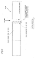
- each of the predetermined sections r1, r2, r3 ... rn is a rectangular region with W1 in width x D1 in thickness, as the section r1 is shown as an example in Fig. 1(b) .
- the "number density of the segregated particle having the predetermined diameter or more" in the section r1 is determined from N/(W1 x D1).
- threshold values of the maximum segregated particle size and of the number density which are used for evaluation of the HIC resistance of the slab, i.e., the respective ranges of the maximum segregated particle size and the number density that avoid the occurrence of the HIC in the steel plate obtained by rolling the slab.
- threshold values are determined previously, but their determination method is not particularly limited to the following method.
- An example of the method for determining the threshold values will include the following steps (i) to (iii). The details of the method will be described below.
- a slab is cast on the same casting conditions as the slab in which the maximum segregated particle size and the number density of the segregated particles are measured, and then the slab is hot-rolled, thereby manufacturing a steel plate for measurement of the threshold value.
- An HIC test is performed on the steel plate to check the presence or absence of HIC occurrence.
- the HIC test is performed by a method specified by the National Association of Corrosion and Engineer (NACE) standard TM0284-2003, as mentioned in Examples below.
- NACE National Association of Corrosion and Engineer
- HIC test it is examined whether or not HIC occurs in a region of a product (steel plate) that corresponds to the region R3 of the slab shown in Fig. 1 .
- the region R3 of the slab is divided into the individual n predetermined sections r1, r2, r3 ... rn in the width direction.
- the regions to be evaluated for the HIC resistance vary depending on the rolling direction during the rolling using the slab shown in Fig. 1 .
- a slab width W product width W.
- the regions corresponding to the "regions R1 and R2 of the slab" are “regions R11 and R12 ranging from both ends of the width W of the product to D/2 of the product width D.
- the region of the product corresponding to the "region R3 of the slab” is a "region R13 with a width W-D, except for regions from both ends of a width W of the product to D/2 of the product width D".
- regions corresponding to the "sections r1, r2, r3 ... rn in the region R3 of the slab” correspond to "sections r11, r12, r13 ... r1n” that are obtained by dividing the region R13 of the product into the individual n predetermined sections in the width direction, respectively.
- each of the predetermined sections r11, r12, r13 ... r1n is a rectangular region with W1 in width x D1 in thickness.
- the width of each slab changes from W before the rolling to Wa after the rolling, and thus the slab width W is smaller than the product width Wa, i.e., slab width W ⁇ product width Wa.
- the regions R21, R22, and R23 corresponding to the slab regions R1, R2, and R3 are determined by a rolling reduction, i.e., product width Wa/slab width W. Among these regions, it is confirmed whether or not HIC occurs in the region R23.
- the segregation degree of the center segregation can be evaluated by the "maximum segregated particle size" and the "number density of the segregated particles” as mentioned above.
- the boundary (threshold value) for determining whether HIC occurs or not due to the center segregation can be represented by a function f ⁇ (x, y) where x is the maximum segregated particle size and y is the number density.
- a "threshold function f ⁇ (x, y) of the maximum segregated particle size and the number density” is determined, and based on this threshold function, the HIC occurrence range is determined.
- the results obtained from the region of the slab and the corresponding region of the product are correlated to each other. For instance,
- the threshold function f ⁇ (x, y) of the maximum segregated particle size and the number density that serves as the boundary of the presence or absence of HIC occurrence is determined from the above-mentioned plurality of results. Based on the threshold function f ⁇ (x, y), the "respective ranges of the maximum segregated particle size and the number density that cause HIC" (HIC occurrence range) and the “respective ranges of the maximum segregated particle size and the number density that avoid the occurrence of HIC" (HIC non-occurrence range) are determined.
- the steel plate in the present invention is a steel plate in which the "maximum segregated particle size x" and the “number density y of the segregated particle having the predetermined diameter or more" are measured at the center part in the thickness direction of the region R3 at the slab cross section at a stage of the slab, and the measured x and y are within the "HIC non-occurrence range" determined by the threshold value f ⁇ (x,y). Since this steel plate is considered to have a low segregation degree of the center segregation zone, no HIC is determined to occur due to the center segregation.
- the threshold value is preferably determined by using the measurement results of the maximum segregated particle size and the number density in a plurality of slabs and the HIC test results.
- the measurement results of the maximum segregated particle size and the number density of the plurality of slabs and the HIC test results can be used to obtain the threshold value with higher accuracy, which can reduce the misjudgment of the presence or absence of HIC occurrence.
- the segregation zone and the HIC resistance may be evaluated by examining one cross section of the slab or product, or alternatively by examining two or more cross sections thereof.
- Fig. 3 hereinafter shows the results obtained by examining a plurality of cross sections of the slab of the same charge.
- Example 1 is an example of examining two cross sections of the slab of the same charge
- Example 2 is an example of examining three cross sections of the slab of the same charge. In either example, the result is obtained by examining the slab that is in conformity with API X65 Grade.
- Example 1 the respective maximum segregated particle sizes of the two cross sections are 1.12 mm and 1.14 mm, and the number density of either cross section is 0 particles/m 2 .
- the respective maximum segregated particle sizes of the three cross sections are 2.23 mm, 2.25 mm, and 2.26 mm, and the number density in each of all cross sections is 1,667 particles/m 2 .
- HIC occurs at the center segregation zones as the starting points.
- the slab in conformity with the API X65 Grade is used for evaluation.
- a slab in another strength grade for example, a slab of API X70 Grade or higher grade does not differ from the API X65 Grade slab in formation of segregation zones or in variations in the features of the segregation zones.
- the number of cross sections to be examined is not limited.
- the examination position (examined surface) of the slab is preferably a stationary part as shown in Examples below, but may be a non-stationary part.
- non-stationary part as used herein means a part casted when the casting condition is varied, for example, a part casted at an initial stage of casting, such as when the casting speed increases, or a part casted at the end of casting, such as when the casting speed decreases.
- a part adjacent to the region subjected to the HIC test is preferably examined. Such a part exhibits substantially the same HIC resistance as the HIC test result and can be evaluated more precisely.
- the above-mentioned maximum segregated particle size and the number density are used to evaluate the HIC resistance. Because of this, the internal quality of the cast strip can be precisely evaluated, so that based on this evaluation result, the HIC resistance can be evaluated at a stage of the cast strip. Consequently, the HIC test that would require several weeks can be omitted, thereby significantly shortening a time period from the manufacture to dispatching.
- Table 1 and Figs. 5 and 6 show the experimental conditions and results for determining the threshold value t ⁇ .
- 7 charges were cast to obtain each of a slab corresponding to the API X65 Grade and a slab corresponding to the API X70 Grade.
- One charge was cast to obtain each of a slab corresponding to the ASME SA516 Grade 60, a slab corresponding to the ASME SA516 Grade 65, and a slab corresponding to the ASME SA516 Grade 70. These slabs were examined for the center segregation in the following way.
- X70 corresponds to API X70 Grade; "X65” to API X65 Grade; "SA516 60” to ASME SA516 Grade 60; “SA516 65” to ASME SA516 Grade 65; and "SA516 70” to ASME SA516 Grade 70.
- the concentrations of C, Mn, Nb, P, and Ca were measured by an emission spectroscopy.
- the S concentration was very low and thus was difficult to measure by the emission spectroscopy. Then, the S concentration was measured by using a combustion-infrared absorption method.
- the casting speed was a drawing speed of the cast strip [m/min.], and was calculated from the diameter (circumferential length) and the rotational speed (the number of revolutions per unit time) of a roll (major roll) in contact with the cast strip.
- the term "stationary part” as used herein means a part that satisfies the following conditions.
- the number of cross sections for examination of the center segregation is shown in Table 1.
- the hot-rolling was performed on the slab through two or more passes.
- a surface temperature of the steel plate was set at 900°C or higher
- a cumulative rolling reduction was 40% or more at an average steel plate temperature of 1,000°C or higher, which was determined by the calculation below, and a rolling reduction per pass was 10% or more.
- another hot-rolling was performed such that a cumulative rolling reduction at 700°C or higher and lower than 900°C was 20% or more, and that a rolling-end temperature was 700°C or higher and lower than 900°C.
- the average steel plate temperature was determined in the following way. Specifically, based on data including a rolling pass schedule during rolling and a cooling method (water-cooling or air-cooling) between the passes, the temperature at any position of the steel plate in the thickness direction was determined by using an appropriate calculation method, such as a finite difference method. Then, the average steel plate temperature was defined as the average of the determined temperatures of the steel strip in a range from the front to back surface thereof. The definition of the "average steel plate temperature" also applied to other steel plates.
- the HIC test was performed after the rolling.
- Figs. 5 and 6 each show the relationship between the '''maximum segregated particle size' and 'number density' " and the "presence or absence of HIC occurrence" confirmed by the above-mentioned HIC test.
- Figs. 5 and 6 are diagrams plotted by taking a plurality of data from steel plates of respective samples Nos. shown in Table 1.
- Fig. 5 shows the examination results of threshold values f ⁇ (x, y) at which HIC occurred in components of the steels shown in Table 2 and belonging to the strength class of API X65 Grade.
- Fig. 6 shows the examination results of threshold values f ⁇ (x, y) at which HIC occurred in components of the steels shown in Table 2 and belonging to the strength class of API X70 Grade.
- the HIC resistance of each slab as the determination target was evaluated using the above-mentioned threshold value.
- the steel with the component composition shown in Table 2 was melted and subjected to continuous casting, thereby producing a slab as the determination target that had the slab thickness D of 280 mm and the slab width W of 2, 100 mm.
- each slab was processed by either of two patterns of hot-rolling and cooling methods, denoted as "TMCP” or "QT” in a "hot-rolling and cooling method” column shown in Table 3. Consequently, steel plates (each having 9 to 90 mm in thickness ⁇ 2,000 to 3,500 mm in width ⁇ 12,000 to 35,000 mm in length) with various component compositions were produced.
- TMCP hot-rolling and cooling methods
- TMCP hot-rolling through two or more passes, in each of which a surface temperature of the steel plate was set at 900°C or higher, a cumulative rolling reduction was 40% or more at an average steel plate temperature of 1,000°C or higher, determined by the calculation, and a rolling reduction per pass was 10% or more.
- TMCP also involved: another hot-rolling such that a cumulative rolling reduction was 20% or more at a temperature of 700°C or higher and lower than 900°C such that that the surface temperature at the end of the rolling was 850°C.
- the "TMCP” further involved: starting to cool the rolled steel plate from a cooling start surface temperature of 750°C or higher at an average cooling rate of 10°C/s and then stopping the cooling at a temperature of 350 to 600°C, followed by air-cooling to the room temperature.
- the above-mentioned "QT” was a method that involved: hot-rolling such that the surface temperature at the end of the rolling was 850°C or higher, followed by air-cooling to the room temperature; quenching by reheating the rolled steel plate to a temperature of 850°C or higher and 950°C or lower; and tempering the steel plate at 600 to 700°C.
- Hot-rolling and cooling method Ca/S (Ca-1.25S)/O Maximum segregated particle size (mm) Number density (particles/m 2 ) Evaluation of HIC resistance of slab Presence or absence of cracking in HIC resistance test Strength class 1 TMCP 7.5 0.96 0.448 0 OK Absence X65 2 TMCP 4.4 0.88 0.439 0 OK Absence X65 3 TMCP 7.5 0.96 0.917 0 OK Absence X65 4 TMCP 4.4 0.88 0.930 0 OK Absence X70 5 TMCP 5.7 1.02 0.962 0 OK Absence X65 6 TMCP 2.7 0.80 1.210 0 OK Absence X65 7 TMCP 3.9 0.73 0.788 0 OK Absence X70 8 TMCP 1.9 0.26 0.552 0 OK Presence X65 9 TMCP 5.4 1.89 0.623 0 OK Presence X65 10 TMCP 5.8 1.63 1.684 333 OK Absence X65 11 TMCP
- Tables 2 and 3 show the following. Steel types Nos. 1 to 7, 10 to 12, 15 to 17, and 20 to 22 satisfied the specified component compositions and restricted the maximum segregated particle size and the number density of each slab within the HIC non-occurrence range, thereby producing the steel plates with excellent HIC resistance in the present invention.
- a time period required from starting of casting to completion of a production of the steel plate that is, a time period until dispatching the steel plate with the sour resistance (casting ⁇ rolling ⁇ dispatching) was 19 days.
- a time period required from starting of casting to dispatching (casting ⁇ rolling ⁇ HIC test ⁇ dispatching) was 28 days, which was a long duration.
- the HIC test after the rolling was able to be omitted, which could significantly shorten the time period from starting of the casting to dispatching, e.g., from 28 days to 19 days.
- the HIC resistance can be evaluated at the stage of the slab as the cast strip without performing the HIC test after the rolling, thereby making it possible to significantly shorten the manufacturing lead time.
- the same HIC test is used for both the determination of the threshold value for evaluating the HIC resistance of a slab and the confirmation of HIC.
- the determination method of the present invention has high accuracy.
Landscapes
- Chemical & Material Sciences (AREA)
- Engineering & Computer Science (AREA)
- Materials Engineering (AREA)
- Mechanical Engineering (AREA)
- Metallurgy (AREA)
- Organic Chemistry (AREA)
- Physics & Mathematics (AREA)
- Thermal Sciences (AREA)
- Crystallography & Structural Chemistry (AREA)
- Heat Treatment Of Steel (AREA)
Abstract
Description
- The present invention relates to a steel plate and a steel pipe for line pipe that have excellent hydrogen-induced cracking resistance. In particular, the present invention relates to a steel plate that has excellent hydrogen-induced cracking resistance and is suitable for use in line pipe for transportation and tanks for storage of natural gas and crude oil, and to a steel pipe for line pipe with excellent hydrogen-induced cracking resistance, obtained by using the steel plate.
- With the development of degradation resources containing hydrogen sulfide, mainly, line pipe for transportation and tanks for storage of oil, gas, etc. , require so-called sour resistance, such as hydrogen-induced cracking resistance or stress-corrosion cracking resistance. Hereinafter, a steel plate that exhibits the adequate sour resistance is sometimes referred to as a "sour-resistant steel plate" in some cases. Hydrogen-induced cracking (hereinafter sometimes referred to as "HIC") is known as a crack caused by the penetration of hydrogen thereinto due to a corrosion reaction with the hydrogen sulfide or the like, and the collection and gasification of the hydrogen at non-metallic inclusions, such as MnS or Nb(C, N).
- HIC is also known to have a tendency to occur in segregation zones, including a center segregation and internal cracks of a cast strip, particularly, at an inclusion such as MnS, as a starting point. For this reason, some techniques for enhancing HIC resistance have been proposed. For example,
Patent Document 1 discloses that a steel material has improved HIC resistance by suppressing segregation degrees of Mn, Nb, and Ti at the center in the thickness direction of a steel plate.Patent Document 2 discloses a method for suppressing HIC that would occur in MnS or a Ca-based acid sulfide as a starting point, by using a parameter formula that includes the contents of Ca, O and S. - These methods suppress the occurrence of a large amount of HIC, but in some cases, fine HIC can occur locally at a number of sites.
- Meanwhile, a steel plate is subjected to melting, casting, and hot-rolling, and then it undergoes an HIC test before being dispatched as a product. However, it takes several weeks to obtain the result of the HIC test. Once the HIC occurs during the HIC test, the above-mentioned steel plate cannot be dispatched as a product with excellent hydrogen-induced cracking resistance. Because of this, the steel plate needs to be manufactured again, that is, melted again to produce a product, and then the product needs to undergo the HIC test again. This increases the manufacturing time period and might possibly result in missing the deadline or the like.
- For this reason, it is considered that if the HIC resistance can be evaluated at the stage of a cast strip after the casting without performing the HIC test after hot rolling, the manufacturing time period can be significantly shortened. As mentioned above, HIC occurs at segregation zones (center segregation, internal cracks) or inclusions, such as MnS, as a starting point. Thus, if these can be evaluated at the stage of the cast strip, the evaluation of the HIC resistance is considered to be possible based on the evaluation results.
- For example, in a conventional method that involves performing an HIC test after rolling, a long procedure A-1 from casting to dispatching is carried out in the following way. In contrast, when the HIC resistance can be evaluated at the stage of the cast strip, the steps of "Sample Preparation (for HIC test) → HIC Test" in performing the HIC test can be omitted as illustrated in a procedure B-1, so that products can be dispatched at an early stage.
- Procedure A-1 : Casting → Rolling → Sample Preparation (for HIC test) → HIC Test → Dispatching
- Procedure B-1: Casting → Evaluation of HIC Resistance → Rolling → Dispatching
- If the result of the HIC test is no good (NG), the conventional method would be to perform the following procedure A-2, where it takes a long time to perform steps from the casting to re-melting. In contrast, when the HIC resistance can be evaluated at the stage of the cast strip as illustrated in the following procedure B-2, even if the evaluation result is NG, the steps of "Rolling → Sample Preparation (for the HIC Test) → HIC Test" in the procedure A-2 below can be omitted, which enables a quick start of re-melting.
- Procedure A-2: Casting → Rolling → Sample Preparation (for HIC test) → HIC Test → Re-Melting
- Procedure B-2: Casting → Evaluation of HIC Resistance → Re-Melting
- As such a method,
Patent Document 3 discloses a method in which internal cracks are evaluated at the stage of the cast strip. In this method, the possibility of a hot charge rolling (HCR) operation is determined based on the evaluation result of internal cracks. -
- Patent Document 1:
JP 2010-209461 A - Patent Document 2:
JP H6-136440 A - Patent Document 3:
JP 2006-198649 A - HIC is more likely to occur not only at an internal crack, but also at a center segregation zone as a starting point. However,
Patent Document 3 does not describe a method for evaluating center segregation. Therefore, the method mentioned inPatent Document 3 is considered to be incapable of evaluating the HIC resistance caused by the center segregation at a stage of a cast strip. - The present invention has been made in view of the foregoing circumstance, and it is an object of the present invention to achieve a steel plate and a steel pipe that have excellent hydrogen-induced cracking resistance, and further to achieve a steel plate and a steel pipe that enable the evaluation of the HIC resistance by an internal quality of a cast strip without performing an HIC test.
- A steel plate having excellent hydrogen-induced cracking resistance according to the present invention that can solve the above-mentioned problem includes, in percent by mass:
- 0.02 to 0.15% of C;
- 0.02 to 0.50% of Si;
- 0.6 to 2.0% of Mn;
- more than 0% and 0.030% or less of P;
- more than 0% and 0.003% or less of S;
- 0.010 to 0.08% of Al;
- 0.0003 to 0.0060% of Ca;
- 0.001 to 0.01% of N;
- more than 0% and 0.0045% or less of O; and
- one or more elements selected from the group consisting of:
- more than 0% and 0.02% or less of REM, and
- more than 0% and 0.010% or less of Zr, with the balance being iron and inevitable impurities, wherein
- a ratio (Ca/S) of the Ca to the S is 2.0 or more,
- the Ca, the S, and the O satisfy a formula below: (Ca -1.25S)/O ≤ 1.80, and
- further, at a stage of a slab, a maximum segregated particle size and a number density of segregated particle having a predetermined diameter or more, at a center part in a thickness direction of the slab are set within respective ranges of the maximum segregated particle size and the number density of the segregated particle having the predetermined diameter or more, that avoid occurrence of hydrogen-induced cracking in the steel plate obtained by rolling the slab.
- The above-mentioned respective ranges of the maximum segregated particle size and the number density of the segregated particle having the predetermined diameter or more, that avoid occurrence of hydrogen-induced cracking may be those previously determined by method including following (i) to (iii):
- (i) the maximum segregated particle size and the number density of segregated particle having the predetermined diameter or more, at the center part in the thickness direction of the slab are measured;
- (ii) a hydrogen-induced cracking test is performed on a steel plate obtained by rolling a slab, which has been cast on the same casting conditions as the above-mentioned slab; and
- (iii) the respective ranges of the maximum segregated particle size and the number density of the segregated particle having the predetermined diameter or more, that avoid occurrence of hydrogen-induced cracking are determined from the maximum segregated particle size and the number density of the segregated particle having the predetermined diameter or more, that are measured in the step (i) and a result of the hydrogen-induced cracking test shown in the step (ii).
- A slab casted on the same casting conditions as the above-mentioned slab may be the slab in which the maximum segregated particle size and the number density of the segregated particle having the predetermined diameter or more, are measured.
- The steel plate may be in an API (The American Petroleum Institute) X65 Grade, and the respective ranges of the maximum segregated particle size and the number density of the segregated particle having the predetermined diameter or more, that avoid occurrence of hydrogen-induced cracking may satisfy either of formulas below:


- The steel plate may be in an API X70 Grade, and the respective ranges of the maximum segregated particle size and the number density of the segregated particle having the predetermined diameter or more, that avoid occurrence of hydrogen-induced cracking may satisfy either of formulas below:


- The steel plate may be in an ASME (American Society of Mechanical Engineers) SA516 Grade 60, and the respective ranges of the maximum segregated particle size and the number density of the segregated particle having the predetermined diameter or more, that avoid occurrence of hydrogen-induced cracking may satisfy either of formulas below:


- The steel plate may be in an ASME SA516 Grade 65, and the respective ranges of the maximum segregated particle size and the number density of the segregated particle having the predetermined diameter or more, that avoid occurrence of hydrogen-induced cracking may satisfy either of formulas below:


- The steel plate may be in an ASME SA516 Grade 70, and the respective ranges of the maximum segregated particle size and the number density of the segregated particle having the predetermined diameter or more, that avoid occurrence of hydrogen-induced cracking may satisfy either of formulas below:


- The steel plate may be in an ASTM (American Society for Testing and Materials) A516 Grade 60, and the respective ranges of the maximum segregated particle size and the number density of the segregated particle having the predetermined diameter or more, that avoid occurrence of hydrogen-induced cracking may satisfy either of formulas below:


- The steel plate may be in an ASTM A516 Grade 65, and the respective ranges of the maximum segregated particle size and the number density of the segregated particle having the predetermined diameter or more, that avoid occurrence of hydrogen-induced cracking may satisfy either of formulas below:


- The steel plate may be in an ASTM A516 Grade 70, and the respective ranges of the maximum segregated particle size and the number density of the segregated particle having the predetermined diameter or more, that avoid occurrence of hydrogen-induced cracking may satisfy either of formulas below:


- The steel plate may further include, as another element, one or more of elements (A) and (B) below:
- (A) in percent by mass, one or more elements selected from the group consisting of more than 0% and 0.005% or less of B, more than 0% and 0.1% or less of V, more than 0% and 1.5% or less of Cu, more than 0% and 1.5% or less of Ni, more than 0% and 1.5% or less of Cr, more than 0% and 1.5% or less of Mo, and more than 0% and 0.06% or less of Nb; and
- (B) in percent by mass, one or more elements selected from the group consisting of more than 0% and 0.03% or less of Ti, and more than 0% and 0.01% or less of Mg.
- The steel plate is suitable for use in line pipe and pressure container. The present invention also includes a steel pipe for a line pipe formed of the steel plate.
- The present invention can provide the steel plate and the steel pipe that surely have the excellent hydrogen-induced cracking resistance. Further, the present invention can provide the steel plate and the steel pipe in which the HIC resistance can be evaluated by the internal quality of a cast strip without performing an HIC test. These steel plates are suitable for use in line pipe for transportation of natural gas and crude oil and pressure container such as tanks for storage of natural gas and crude oil, and the like.
-
-
Fig. 1(a) is a cross-sectional view of a slab, andFig. 1 (b) is an enlarged view of a section r1. -
Fig. 2 shows cross-sectional views of the slab and cross-sectional views of a product. -
Fig. 3 shows results of examination about the relationship between the HIC resistance, and the maximum segregated particle sizes and the number densities at a plurality of cross sections. -
Fig. 4 is a diagram for explaining an examined surface of the slab. -
Fig. 5 is a diagram showing the relationship between the maximum segregated particle sizes and number densities and the presence or absence of HIC occurrence when using steels of API X65 Grade and the like in Examples. -
Fig. 6 is a diagram showing the relationship between the maximum segregated particle sizes and number densities and the presence or absence of HIC occurrence when using steels of API X70 Grade and the like in Examples. - The inventors have diligently studied to solve the foregoing problems. First, the inventors have focused on the tendency for HIC to occur at a MnS inclusion as a starting point. As a result, it is conceived that by causing a steel to contain a rare earth element or Zr, which has a desulfurization effect, the formation of MnS can be suppressed to improve the hydrogen-induced cracking resistance. Furthermore, an appropriate content of such an element is found to efficiently exhibit the desulfurization effect as mentioned later.
- Next, the inventors have focused on the tendency for HIC to occur at a segregation zone as a starting point. Consequently, attention is paid to a "segregation degree of center segregation" among segregation zones, particularly, the "maximum segregated particle size (maximum diameter of a segregated particle)" and the "number density of the segregated particle having the predetermined diameter or more". It is found that if these parameters at a stage of a slab are restricted within certain respective ranges, a steel plate with higher hydrogen-induced cracking resistance can be obtained, and furthermore products can be dispatched at an early stage. This matter will be described in detail below.
- The component composition of a steel will be described below.
- To ensure the excellent HIC resistance, the component composition of the steel needs to be controlled. Furthermore, also to ensure the high strength, excellent weldability, and the like, which are other properties required as, for example, the steel for line pipe, the component composition of the steel plate needs to be as follows. The reasons for specifying the contents of the respective components, including the aforesaid rare earth elements and Zr, will be described below.
- Carbon (C) is an element essential to ensure the strength of a base metal and a weld bead. Thus, the C content needs to be 0.02% or more. The C content is preferably 0.03% or more, and more preferably 0.05% or more. On the other hand, an extremely high C content degrades the heat-affected zone (HAZ) toughness and the weldability of the steel. Any excessive C content is more likely to form NbC or island-shaped martensite, which possibly becomes as the starting point of HIC or a fracture propagation route. Thus, the C content needs to be 0.15% or less. The C content is preferably 0.12% or less, and more preferably 0.10% or less.
- Silicon (Si) has a deoxidation function and is effective in improving the strength of a base metal and a weld bead. To exhibit these effects, the Si content is set at 0.02% or more. The Si content is preferably 0.05% or more, and more preferably 0.15% or more. However, an extremely high Si content degrades the weldability and toughness of the steel. Any excessive Si content forms island-shaped martensite to generate and propagate HIC. Accordingly, the Si content needs to be suppressed to 0.50% or less. The Si content is preferably 0.45% or less, and more preferably 0.35% or less.
- Manganese (Mn) is an element that is effective in improving the strength of a base metal and a weld bead. In the present invention, the Mn content is set at 0.6% or more. The Mn content is preferably 0.8% or more, and more preferably 1.0% or more. However, an extremely high Mn content forms MnS, degrading not only the hydrogen-induced cracking resistance, but also the HAZ toughness and weldability. Thus, the upper limit of Mn content is set at 2.0%. The Mn content is preferably 1.8% or less, more preferably 1.5% or less, and still more preferably 1.2% or less.
- Phosphorus (P) is an element inevitably contained in steel. When the P content exceeds 0.030%, the roughness of a base metal and a HAZ are significantly degraded, and the hydrogen-induced cracking resistance of the steel is also degraded. Thus, in the present invention, the P content is restricted to 0.030% or less. The P content is preferably 0.020% or less, and more preferably 0.010% or less.
- Sulfur (S) is an element that forms a large amount of MnS to significantly degrade the hydrogen-induced cracking resistance when contained in a large amount. Thus, in the present invention, the upper limit of S content is 0.003%. The S content is preferably 0.002% or less, more preferably 0.0015% or less, and still more preferably 0.0010% or less. Thus, the S content is desirably low from the viewpoint of improving the hydrogen-induced cracking resistance.
- Aluminum (Al) is a strong deoxidizing element. When the Al content is low, the Ca concentration in the oxide tends to increase, that is, the Ca-based inclusions are more likely to be formed at a superficial layer of a steel plate, causing fine HIC. Thus, in the present invention, the Al content needs to be 0.010% or more. The Al content is preferably 0.020% or more, and more preferably 0.030% or more. On the other hand, when the Al content is extremely high, an Al oxide is formed in a cluster shape and becomes a starting point of hydrogen-induced cracking. Thus, the Al content needs to be 0.08% or less. The Al content is preferably 0.06% or less, and more preferably 0.05% or less.
- Calcium (Ca) serves to control the form of a sulfide and has an effect of suppressing the formation of MnS by forming CaS. To obtain this effect, the Ca content needs to be 0.0003% or more. The Ca content is preferably 0.0005% or more, and more preferably 0.0010% or more. On the other hand, when the Ca content exceeds 0.0060%, HIC occurs at many sites from the Ca-based inclusions as the starting point. Thus, in the present invention, the upper limit of Ca content is set at 0.0060%. The Ca content is preferably 0.0045% or less, more preferably 0.0035% or less, and still more preferably 0.0025% or less.
- Nitrogen (N) precipitates as TiN in a steel microstructure, preventing austenite grains in a HAZ zone from being coarsened and further promoting ferrite transformation to thereby improve the toughness of the HAZ zone. To obtain these effects, the N content needs to be 0.001% or more. The N content is preferably 0.003% or more, and more preferably 0.0040% or more. An extremely high N content, however, degrades the toughness of the HAZ by the presence of the solid-solute N. The N content needs to be 0.01% or less. The N content is preferably 0.008% or less, and more preferably 0.0060% or less.
- An oxygen (O) content is desirably low from the viewpoint of improving the cleanliness of a steel. An extremely high O content degrades the toughness of the steel, and additionally causes HIC at an oxide as a starting point, thereby degrading the hydrogen-induced cracking resistance. In this regard, the O content needs to be 0.0045% or less, and is preferably 0.0030% or less, and more preferably 0.0020% or less.
- As mentioned above, S forms MnS as a sulfide-based inclusion, and HIC might occur at the MnS as a starting point. Thus, the sulfide-based inclusion in the steel has its form controlled as CaS by adding Ca, thereby rendering S harmless for the HIC resistance. To sufficiently exhibit these effects, the Ca/S needs to be set at 2.0 or more. The Ca/S is preferably 2.5 or more, and more preferably 3.0 or more. Note that the upper limit of Ca/S is approximately 17 based on the Ca content and S content specified by the present invention.

- To avoid the occurrence of HIC due to a Ca-based oxysulfide, it is effective to suppress, especially, CaO that is the most likely to form aggregates among Ca-based inclusions. For this reason, a Ca content (Ca - 1.25S) that is obtained by subtracting a content in Ca present as a sulfide (CaS) in the steel from the total Ca content in the steel must not be excessive relative to the O content. When the Ca content (Ca - 1.25S) is excessive relative to the O content, CaO is more likely to be formed as an oxide-based inclusion, which makes it easier for aggregates of the CaO (coarse Ca-based inclusions) to be formed in a larger amount at a superficial layer of a steel plate. Since these coarse Ca-based inclusions serve as the starting point of HIC, the (Ca - 1. 25S) /O needs to be 1.80 or less in order to obtain the excellent HIC resistance. (Ca - 1.25S)/O is preferably 1.40 or less, more preferably 1.30 or less, still more preferably 1.20 or less, and particularly preferably 1.00 or less. Like CaO, to suppress Al2O3 that tends to form aggregates, the lower limit of (Ca - 1.25S)/O is approximately 0.1.
- A rare earth metal (REM) is an element that is effective in enhancing the hydrogen-induced cracking resistance by suppressing the formation of MnS through the desulfurization effect as mentioned above. To exhibit such effects, the REM content is preferably 0.0002% or more. The REM content is more preferably 0.0005% or more, and still more preferably 0.0010% or more. On the other hand, if REM is contained in a large amount, the effect is saturated. Thus, the upper limit of the REM content needs to be 0.02%. From the viewpoint of preventing the clogging of an immersion nozzle during casting to enhance the productivity, the REM content is preferably 0.015% or less, more preferably 0.010% or less, and still more preferably 0.0050% or less. Note that in the present invention, REM means lanthanoid elements (15 elements from La to Lu), scandium (Sc), and yttrium (Y).
- Zirconium (Zr) serves to form an oxide and disperse it finely in steel, while improving the HIC resistance by the desulfurization effect, thereby contributing to improving the HAZ toughness. To exhibit these effects, the Zr content is preferably set at 0.0003% or more. The Zr content is more preferably 0.0005% or more, even more preferably 0.0010% or more, and much more preferably 0.0015% or more. On the other hand, the addition of any excessive Zr forms coarse inclusions to degrade the hydrogen-induced cracking resistance and the toughness of a base metal. Thus, the Zr content needs to be 0.010% or less. The Zr content is preferably 0.0070% or less, more preferably 0.0050% or less, and even more preferably 0.0030% or less.
- The components of the steel (steel plate, steel pipe) in the present invention have been mentioned above, with the balance being iron and inevitable impurities. In addition to the elements mentioned above, the steel further includes:
- (a) one or more elements selected from the group consisting of B, V, Cu, Ni, Cr, Mo, and Nb in the following contents, thereby making it possible to enhance the strength and toughness; and/or
- (b) one or more elements selected from the group consisting of Ti and Mg in the following contents, thereby making it possible to improve the HAZ toughness and to promote the desulfurization, thus further improving the HIC resistance. These elements will be described in detail below.
- Boron (B) enhances the hardenability of a steel and the strength of a base metal and a weld bead. Furthermore, B is bonded to N to precipitate BN while the heated HAZ zone is cooled in welding, thus promoting ferrite transformation from the inside of an austenite grain. In this way, B improves the HAZ toughness. To obtain these effects, the B content is preferably 0.0002% or more. The B content is more preferably 0.0005% or more, and still more preferably 0.0010% or more. However, any excessive B content degrades the toughness of a base metal and a HAZ zone, thus leading to degradation in the weldability. Thus, the B content is preferably 0.005% or less. The B content is more preferably 0.004% or less, and still more preferably 0.0030% or less.
- Vanadium (V) is an element effective in improving the strength of steel. To obtain this effect, the V content is preferably 0.003% or more, and more preferably 0.010% or more. On the other hand, when the V content exceeds 0.1%, the weldability and the toughness of a base metal would be degraded. Thus, the V content is preferably 0.1% or less, and more preferably 0.08% or less.
- Copper (Cu) is an element effective in improving the hardenability of steel. To obtain this effect, the Cu content is preferably 0.01% or more. The Cu content is more preferably 0.05% or more, and still more preferably 0.10% or more. However, when the Cu content exceeds 1.5%, the toughness of steel is degraded. Thus, the Cu content is preferably 1.5% or less. The Cu content is more preferably 1.0% or less, and still more preferably 0.50% or less.
- Nickel (Ni) is an element effective in improving the strength and toughness of a base metal and a weld bead. To obtain these effects, the Ni content is preferably 0.01% or more. The Ni content is more preferably 0.05% or more, and still more preferably 0.10% or more. However, an extremely high Ni content leads to an excessively expensive steel for a structure. From the economical aspect, the Ni content is preferably 1.5% or less. The Ni content is more preferably 1.0% or less, and still more preferably 0.50% or less.
- Chromium (Cr) is an element effective in improving the strength of steel. To obtain such an effect, the Cr content is preferably 0.01% or more. The Cr content is more preferably 0.05% or more, and still more preferably 0.10% or more. On the other hand, when the Cr content exceeds 1.5%, the HAZ toughness of the steel is degraded. Thus, the Cr content is preferably 1.5% or less. The Cr content is more preferably 1.0% or less, and still more preferably 0.50% or less.
- Molybdenum (Mo) is an element effective in improving the strength and toughness of a base metal. To exhibit this effect, the Mo content is preferably 0.01% or more. The Mo content is more preferably 0.05% or more, and still more preferably 0.10% or more. However, when the Mo content exceeds 1.5%, the HAZ toughness and weldability of the steel are degraded. Thus, the Mo content is preferably 1.5% or less, more preferably 1.0% or less, and still more preferably 0.50% or less.
- Niobium (Nb) is an element effective in enhancing the strength of steel and the toughness of a base metal without degrading its weldability. To obtain this effect, the Nb content is preferably 0.002% or more. The Nb content is more preferably 0.010% or more, and still more preferably 0.020% or more. However, when the Nb content exceeds 0.06%, the toughness of the base metal and HAZ is degraded. Thus, in the present invention, the upper limit of Nb content is preferably set at 0.06%. The Nb content is more preferably 0.050% or less, still more preferably 0.040% or less, and yet more preferably 0.030% or less.
- Titanium (Ti) precipitates as TiN in steel, thereby preventing austenite grains in a HAZ zone from being coarsened during welding and thereby promoting the ferrite transformation. Thus, Ti is an element that is effective in improving the toughness of the HAZ zone. Furthermore, Ti exhibits the desulfurization effect, and thus is an element that is effective in improving the HIC resistance. To obtain these effects, the Ti content is preferably 0.003% or more, more preferably 0.005% or more, and still more preferably 0.010% or more. On the other hand, any excessive Ti content leads to an increase in the amount of solid-solute Ti and precipitated TiC, thus degrading the toughnesses of a base metal and a HAZ zone. Thus, the Ti content is preferably 0.03% or less, and more preferably 0.02% or less.
- Magnesium (Mg) is an element that is effective in improving the toughness of steel through refinement of crystal grains, and also effective in improving the HIC resistance because of its desulfurization effect. To obtain these effects, the Mg content is preferably 0.0003% or more. The Mg content is more preferably 0.001% or more. On the other hand, an excessive Mg content saturates its effect. Thus, the upper limit of the Mg content is preferably 0.01%. The Mg content is more preferably 0.005% or less.
- In the steel plate of the present invention, at a stage of a slab, a maximum segregated particle size and a number density of segregated particle having a predetermined diameter or more, at a center part in a thickness direction of the slab are set within respective ranges of the maximum segregated particle size and the number density of the segregated particle having the predetermined diameter or more, that avoid occurrence of hydrogen-induced cracking in the steel plate obtained by rolling the slab. Because of this, the steel plate of the present invention has excellent hydrogen-induced cracking resistance. The term "above-mentioned ranges" as used herein means the previously-determined ranges of the maximum segregated particle size and the number density of the segregated particle having the predetermined diameter or more, that avoid the occurrence of HIC in the steel plate obtained by rolling the slab.
- In this way, the segregation degree of center segregation at a stage of the slab is evaluated, specifically, the "maximum segregated particle size (maximum diameter of a segregated particle)" and the "number density of the segregated particle having the predetermined diameter or more" are set within the respective predetermined ranges. This arrangement can produce a steel plate with high hydrogen-induced cracking resistance, and can dispatch products at an early stage. The reason for this will be described below. Note that in the following, the "number density of the segregated particle having the predetermined diameter or more" will be simply referred to as the "number density of segregated particles" or "number density" in some cases.
- First, a description will be given on the segregation degree of the center segregation, and the maximum segregated particle size and the number density, which serve as evaluation indexes of the segregation degree.
- Segregation of components is present at internal cracks or center segregation zones of the slab. As the segregation degree of the component becomes higher, HIC is more likely to occur, which is well known, for example, as described in
JP 2007-136496 A - Note that segregation is also present between secondary dendritic branches. That is, microsegregation can also occur. However, the spacing between the secondary dendritic branches is so small that no HIC propagates and extends. Thus, this state is not problematic in terms of the quality. Therefore, the present invention does not consider the microsegregation.
- In the present invention, the segregation degree of the center segregation is evaluated from the "maximum segregated particle size" and the "number density of the segregated particle having the predetermined diameter or more". Various methods for examining the segregation degree of the center segregation have been proposed. There is a correlation between the "segregated particle size" and the "segregation degree of the center segregation". As the "segregated particle size" is increased, the "segregation degree of the center segregation" tends to become higher (see reference: NKK technical report No. 121 (1988)). That is, there is a correlation between the maximum segregated particle size and the segregation degree of the center segregation. As the "segregation degree of the center segregation" becomes higher, HIC is more likely to occur. Thus, as the maximum segregated particle size is increased, HIC is also more likely to occur.
- The "predetermined diameter" mentioned in the above-mentioned "number density of the segregated particle having the predetermined diameter or more" can be set at the same diameter as a "predetermined diameter" mentioned in a "number density m1 of segregated particle having a predetermined diameter or more", which is measured in a section r1 of the slab shown in
Fig. 2(a) to be mentioned later. For example, when the "predetermined diameter" obtained upon measurement of the slab is, for example, 1.2 mm in diameter, the "predetermined diameter" of a product can also be set at 1.2 mm in diameter. - There is also a correlation between the "number density of the segregated particle having the predetermined diameter or more" and the "maximum segregated particle size". As the number density increases, the "maximum segregated particle size" tends to be larger (see reference: CAMP-ISIJ Vol. 2 (1989), p. 1150). As mentioned above, as the maximum segregated particle size is increased, the "segregation degree of the center segregation" tends to become higher. Thus, as the above-mentioned number density is increased, the "segregation degree of the center segregation" becomes higher, that is, HIC is more likely to occur.
- As can be seen from these facts, it is first found that the HIC resistance can be evaluated by the "maximum segregated particle size" and the "number density of the segregated particle having the predetermined diameter or more", whereby the HIC can be suppressed by controlling them together, i.e., the "maximum segregated particle size" and the "number density of the segregated particle having the predetermined diameter or more".
- Then, the inventors have found that if the HIC resistance of a steel plate after rolling can be determined in advance by using the above-mentioned maximum segregated particle size and the number density of a steel strip at a stage of a slab, i.e., after casting and before rolling, the HIC test does not need to be performed on the steel plate as a product, thereby omitting a step therefor. Consequently, products can be dispatched at an early stage. In particular, the above-mentioned maximum segregated particle size and the number density can be virtually measured as mentioned below, which has advantages of being capable of easily examining the segregation degree in a short time.
- Next, a description will be given on the way to determine the segregation degree of center segregation in a target slab, specifically, the above-mentioned maximum segregated particle size and the number density.
- First, a slab obtained by casting is cut in the thickness direction, i.e., in the direction perpendicular to the casting direction as shown in
Fig. 1 , and then is examined for the segregation degree of the center segregation. - The level of the center segregation (segregated particle size, the number of segregated particle having the predetermined particle size or more) is varied in the slab width direction and thus occasionally deteriorates at a specific part of the slab in the width direction. As illustrated in
Fig. 1 , by setting a cross section perpendicular to the casting direction as an object to be examined, a part where the center segregation becomes worst can be examined. - On the slab cross section shown in
Fig. 1 , a region R3 in the slab, with a width W-D, except for regions from both ends of a slab width W to D/2 of the slab thickness D, is examined for indexes of the segregation degree of the center segregation, i.e., the "maximum segregated particle size" and the "number density of the segregated particle having the predetermined diameter or more". - The reason why the above-mentioned region R3 is examined is as follows. That is, the center segregation is a defect formed at a final solidification zone. As shown in
Fig. 1 , the regions R1 and R2 are cooled from a wide-surface side and a narrow-surface side, while the region R3 is mainly cooled only from a wide-surface side. In the region R3, solidification proceeds from the wide surface toward the center in the thickness direction of the slab, and thereby the center part in the thickness direction of the slab becomes the final solidification zone. The center segregation occurs in the vicinity of the center part in the thickness direction of the slab, which is the final solidification zone in the region R3. For this reason, the present invention examines the segregation degree of the center segregation in the vicinity of the center part in the thickness direction of the region R3 as mentioned above. - Now, a description will be given on one example of a measurement method for the "maximum segregated particle size" and the "number density of the segregated particles" with reference to
Fig. 1 . - As shown in
Fig. 1(a) , the vicinity of the center part in the thickness direction of the region R3 in the slab (for example, ±15 mm from the center of the thickness D) is divided into individual n predetermined sections r1, r2, r3 ... rn (where n is a natural number of 1 or more) in the width direction. Then, the "maximum segregated particle size" and the "number density" in each section are measured. Here, each of the predetermined sections r1, r2, r3 ... rn is a rectangular region with W1 in width x D1 in thickness, as the section r1 is shown as an example inFig. 1(b) . - Regarding the above-mentioned "number density", i.e., the number density of the segregated particle having the predetermined diameter or more, as shown in
Fig. 1(b) , suppose that N segregated particles, each having the predetermined diameter or more, exist in the section r1. In this case, the "number density of the segregated particle having the predetermined diameter or more" in the section r1 is determined from N/(W1 x D1). - Then, a description will be given on the way to determine threshold values of the maximum segregated particle size and of the number density, which are used for evaluation of the HIC resistance of the slab, i.e., the respective ranges of the maximum segregated particle size and the number density that avoid the occurrence of the HIC in the steel plate obtained by rolling the slab.
- The above-mentioned threshold values are determined previously, but their determination method is not particularly limited to the following method. An example of the method for determining the threshold values will include the following steps (i) to (iii). The details of the method will be described below.
- (i) The maximum segregated particle size and the number density of the segregated particle having the predetermined diameter or more, at a center part in a thickness direction of the slab are measured.
- (ii) An HIC test is performed on a steel plate that is obtained by rolling a slab, which has been cast on the same casting conditions as the above-mentioned slab.
- (iii) The respective ranges of the maximum segregated particle size and the number density of the segregated particle having the predetermined diameter or more, that avoid occurrence of hydrogen-induced cracking are determined from the maximum segregated particle size and the number density of the segregated particle having the predetermined diameter or more, that are measured in the step (i) and a result of the HIC test shown in the step (ii).
- A slab is cast on the same casting conditions as the slab in which the maximum segregated particle size and the number density of the segregated particles are measured, and then the slab is hot-rolled, thereby manufacturing a steel plate for measurement of the threshold value. An HIC test is performed on the steel plate to check the presence or absence of HIC occurrence. The HIC test is performed by a method specified by the National Association of Corrosion and Engineer (NACE) standard TM0284-2003, as mentioned in Examples below.
- The term "same casting conditions" as used herein includes: i) a casting speed is constant, ii) an abnormal state in operation, such as clogging of a nozzle, does not occur, and iii) cooling conditions and a distance between rolls are the same. When determining the threshold values, the "segregation degree obtained by examining a slab" is related to the "HIC test result for a product". However, if the HIC resistances of the slab and its product are different from each other, the threshold value cannot be determined. The operation factors i) to iii) significantly affect the center segregation, which will also affect the HIC resistance. Thus, the different operation factors lead to different HIC resistances. For this reason, the steel plate for the HIC test is preferably one obtained by manufacturing using a slab which has been cast on the same casting conditions (operation factors) as the slab in which the maximum segregated particle size and the number density are examined. In particular, the slab in which the above-mentioned maximum segregated particle size and the number density are examined is preferably the same as the slab for the HIC test.
- In the HIC test, it is examined whether or not HIC occurs in a region of a product (steel plate) that corresponds to the region R3 of the slab shown in
Fig. 1 . Specifically, as shown inFig. 1 , the region R3 of the slab is divided into the individual n predetermined sections r1, r2, r3 ... rn in the width direction. Then, it is examined whether or not HIC occurs in regions of the product (steel plate) that correspond to the respective regions r1, r2, r3 ... rn. As illustrated inFig. 2 , the regions to be evaluated for the HIC resistance vary depending on the rolling direction during the rolling using the slab shown inFig. 1 . - When rolling the slab in the casting direction, that is, when the rolling direction is identical to the casting direction, as shown in
Fig. 2(a) , the width of the region does not change before and after the rolling, and thus a slab width W is the same as a product width W, i.e., slab width W = product width W. In this case, as illustrated inFig. 2(a) , the regions corresponding to the "regions R1 and R2 of the slab" are "regions R11 and R12 ranging from both ends of the width W of the product to D/2 of the product width D. The region of the product corresponding to the "region R3 of the slab" is a "region R13 with a width W-D, except for regions from both ends of a width W of the product to D/2 of the product width D". - As shown in
Fig. 2(a) , regions corresponding to the "sections r1, r2, r3 ... rn in the region R3 of the slab" correspond to "sections r11, r12, r13 ... r1n" that are obtained by dividing the region R13 of the product into the individual n predetermined sections in the width direction, respectively. Here, each of the predetermined sections r11, r12, r13 ... r1n is a rectangular region with W1 in width x D1 in thickness. - On the other hand, as shown in
Fig. 2(b) , when rolling the slab in the width direction, that is, when the rolling direction includes the width direction, the width of each slab changes from W before the rolling to Wa after the rolling, and thus the slab width W is smaller than the product width Wa, i.e., slab width W < product width Wa. In this case, as shown inFig. 2(b) , the regions R21, R22, and R23 corresponding to the slab regions R1, R2, and R3 are determined by a rolling reduction, i.e., product width Wa/slab width W. Among these regions, it is confirmed whether or not HIC occurs in the region R23. - The respective ranges of the maximum segregated particle size and the number density that avoid the occurrence of HIC are determined from the above-mentioned "'maximum segregated particle size' and 'number density' that are obtained by the examination of the slab" and the above-mentioned "the HIC test result of the product".
- The segregation degree of the center segregation can be evaluated by the "maximum segregated particle size" and the "number density of the segregated particles" as mentioned above. Thus, the boundary (threshold value) for determining whether HIC occurs or not due to the center segregation can be represented by a function fθ(x, y) where x is the maximum segregated particle size and y is the number density. In the present invention, a "threshold function fθ(x, y) of the maximum segregated particle size and the number density" is determined, and based on this threshold function, the HIC occurrence range is determined.
- When determining the threshold function fθ(x, y), the results obtained from the region of the slab and the corresponding region of the product are correlated to each other. For instance,
- (I) in the case of rolling the slab in the casting direction as illustrated in
Fig. 2(a) , suppose that the product region r11 is in the state of the "presence of HIC occurrence", the product region r12 is in the state of the "presence of HIC occurrence", ... the product region r1n is in the state of the "absence of HIC occurrence" in the HIC test. The determination is made as follows. - (I-1) when the slab region r1 has the maximum segregated particle size x1 and the number density m1, the determination of the "presence of HIC occurrence" is made as the result of the product region r11;
- (I-2) when the slab region r2 has the maximum segregated particle size x2 and the number density m2, the determination of the "presence of HIC occurrence" is made as the result of the product region r12; and
- (1-3) when the slab region rn has the maximum segregated particle size xn and the number density mn, the determination of the "absence of HIC occurrence" is made as the result of the product region r1n.
- (II) In the case of rolling the slab in the width direction as illustrated in
Fig. 2(b) , suppose that the product region r21 is in the state of the "presence of HIC occurrence", the product region r22 is in the state of the "presence of HIC occurrence", ... the product region r2n is in the state of the "absence of HIC occurrence" in the HIC test. The determination is made as follows: - (II-1) when the slab region r1 has the maximum segregated particle size x1 and the number density m1, the determination of the "presence of HIC occurrence" is made as the result of the product region r21;
- (II-2) when the slab region r2 has the maximum segregated particle size x2 and the number density m2, the determination of the "presence of HIC occurrence" is made as the result of the product region r22; and
- (II-3) when the slab region rn has the maximum segregated particle size xn and the number density mn, the determination of the "absence of HIC occurrence" is made as the result of the product region r2n.
- The threshold function fθ(x, y) of the maximum segregated particle size and the number density that serves as the boundary of the presence or absence of HIC occurrence is determined from the above-mentioned plurality of results. Based on the threshold function fθ(x, y), the "respective ranges of the maximum segregated particle size and the number density that cause HIC" (HIC occurrence range) and the "respective ranges of the maximum segregated particle size and the number density that avoid the occurrence of HIC" (HIC non-occurrence range) are determined. If the measured values of the maximum segregated particle size and the number density of the target slab are within the above-mentioned HIC occurrence range, the evaluation result of the HIC resistance of the slab is rated as "NG", that is, re-melting is determined to be necessary. If they are within the above-mentioned HIC non-occurrence range, the evaluation result of the HIC resistance is rated as "OK", that is, the product obtained by sequentially rolling is also determined to have the evaluation of the HIC resistance rated as "OK". In this way, the present invention can precisely evaluate or analyze the internal quality of a slab by using the maximum segregated particle size and the number density for the evaluation of the HIC resistance, and thereby can evaluate the HIC resistance at a stage of the slab. Consequently, the HIC test that would require several weeks can be omitted, thereby significantly shortening a time period from the manufacture to dispatching.
- The steel plate in the present invention is a steel plate in which the "maximum segregated particle size x" and the "number density y of the segregated particle having the predetermined diameter or more" are measured at the center part in the thickness direction of the region R3 at the slab cross section at a stage of the slab, and the measured x and y are within the "HIC non-occurrence range" determined by the threshold value fθ(x,y). Since this steel plate is considered to have a low segregation degree of the center segregation zone, no HIC is determined to occur due to the center segregation.
- Note that the threshold value is preferably determined by using the measurement results of the maximum segregated particle size and the number density in a plurality of slabs and the HIC test results. The measurement results of the maximum segregated particle size and the number density of the plurality of slabs and the HIC test results can be used to obtain the threshold value with higher accuracy, which can reduce the misjudgment of the presence or absence of HIC occurrence.
- The segregation zone and the HIC resistance may be evaluated by examining one cross section of the slab or product, or alternatively by examining two or more cross sections thereof.
Fig. 3 hereinafter shows the results obtained by examining a plurality of cross sections of the slab of the same charge. InFig. 3 , Example 1 is an example of examining two cross sections of the slab of the same charge, and Example 2 is an example of examining three cross sections of the slab of the same charge. In either example, the result is obtained by examining the slab that is in conformity with API X65 Grade. - As shown in
Fig. 3 , in Example 1, the respective maximum segregated particle sizes of the two cross sections are 1.12 mm and 1.14 mm, and the number density of either cross section is 0 particles/m2. In the HIC test, no HIC occurs at the center segregation zone as a starting point on either cross section. In Example 2, the respective maximum segregated particle sizes of the three cross sections are 2.23 mm, 2.25 mm, and 2.26 mm, and the number density in each of all cross sections is 1,667 particles/m2. At all the cross sections, HIC occurs at the center segregation zones as the starting points. - In this way, regarding the slab of the same charge, even different cross sections of the slab exhibit substantially the same results. In addition, it is confirmed that also when examining the cross section of each of 50 charges, the respective charges show substantially the same results without misjudgment, so that the precise evaluation can be achieved.
- Although in the examples shown in
Fig. 3 , the slab in conformity with the API X65 Grade is used for evaluation. Alternatively, a slab in another strength grade, for example, a slab of API X70 Grade or higher grade does not differ from the API X65 Grade slab in formation of segregation zones or in variations in the features of the segregation zones. Thus, the number of cross sections to be examined is not limited. - The examination position (examined surface) of the slab is preferably a stationary part as shown in Examples below, but may be a non-stationary part. The term "non-stationary part" as used herein means a part casted when the casting condition is varied, for example, a part casted at an initial stage of casting, such as when the casting speed increases, or a part casted at the end of casting, such as when the casting speed decreases. When intended to examine the non-stationary part, as shown in
Fig. 4 , a part adjacent to the region subjected to the HIC test is preferably examined. Such a part exhibits substantially the same HIC resistance as the HIC test result and can be evaluated more precisely. - In the present invention, the above-mentioned maximum segregated particle size and the number density are used to evaluate the HIC resistance. Because of this, the internal quality of the cast strip can be precisely evaluated, so that based on this evaluation result, the HIC resistance can be evaluated at a stage of the cast strip. Consequently, the HIC test that would require several weeks can be omitted, thereby significantly shortening a time period from the manufacture to dispatching.
- The present application claims priority to Japanese Patent Application No.
2014-266490 filed on December 26, 2014 2015-208021 - The present invention will be more specifically described below by way of Examples, but is not limited to the following Examples. Various modifications can be obviously made to these Examples as long as they are adaptable to the above-mentioned and below-mentioned concepts and are included within the scope of the present invention.
- Table 1 and
Figs. 5 and 6 show the experimental conditions and results for determining the threshold value tθ. First, 7 charges were cast to obtain each of a slab corresponding to the API X65 Grade and a slab corresponding to the API X70 Grade. One charge was cast to obtain each of a slab corresponding to the ASME SA516 Grade 60, a slab corresponding to the ASME SA516 Grade 65, and a slab corresponding to the ASME SA516 Grade 70. These slabs were examined for the center segregation in the following way. Note that in Table 1 mentioned above and Table 3 mentioned below, "X70" corresponds to API X70 Grade; "X65" to API X65 Grade; "SA516 60" to ASME SA516 Grade 60; "SA516 65" to ASME SA516 Grade 65; and "SA516 70" to ASME SA516 Grade 70. - The conditions shown in Table 1 will be described.
- The concentrations of C, Mn, Nb, P, and Ca were measured by an emission spectroscopy. The S concentration was very low and thus was difficult to measure by the emission spectroscopy. Then, the S concentration was measured by using a combustion-infrared absorption method.
-

- The casting speed was a drawing speed of the cast strip [m/min.], and was calculated from the diameter (circumferential length) and the rotational speed (the number of revolutions per unit time) of a roll (major roll) in contact with the cast strip.
- Steels having component compositions within the range specified by the present invention and in which their molten steels in a tundish had component compositions shown in Table 1 were melted and subjected to continuous casting, thereby producing cast strips or slabs, each having a thickness of 280 mm.
- Each slab was cut at a stationary part in an entire length of 10 to 15 m, and the segregation degree of the center segregation in the stationary part was then examined in the following way. The term "stationary part" as used herein means a part that satisfies the following conditions. The number of cross sections for examination of the center segregation is shown in Table 1.
- 1) Casting speed was constant.
- 2) An abnormal state in operation, such as clogging of an immersion nozzle, did not occur.
- 3) Cooling conditions did not change.
- 4) A distance between rolls did not change.
-
- (1) The cross section of the slab was polished to a level of an 800-grit level in a range of the width W-D, except for regions from both ends of the width W to D/2 in the width direction.
- (2) The polished surface was corroded with 20 g/L of picric acid, 5 g/L of cupric chloride and 60 mL/L of a surfactant.
- (3) The maximum segregated particle size was calculated in the following method.
- (3-1) A part of the slab, with the width W-D, except for the regions from both ends of the slab width W to D/2, was divided into sections, each having a size of 110 mm in the width direction. In each section, a major axis a and a minor axis b of a segregated particle existing in a range of ±15 mm from the center in the thickness direction, i.e., Dn = 0.03 m, were visually measured by means of a ruler.
- (3-2) A circular equivalent diameter ds of the segregated particle was calculated by a formula below.


- (3-3) The maximum particle size of the segregated particle, i.e., the "maximum segregated diameter x" was defined as the maximum particle size dsmax of particle sizes ds in all sections.
- (4) The number density of segregated particle having the predetermined diameter or more, was calculated in the following method.
- (4-1) A part of the slab, with the width W-D, except for the regions from both ends of the slab width W to D/2, was divided into sections, each having a size of 110 mm in the width direction, i.e., Wn = 0.11m. In each section, the number of segregated particles (each segregated particle having a larger size than a circle with a diameter of 1.2 mm) existing in a range of ±15 mm from the center of the section in the thickness direction was visually counted. Here, whether or not the segregated particle is larger than the circle with a diameter of 1.2 mm was confirmed by overlapping a transparent sheet having a printed circle with a diameter of 1.2 mm, on the segregated particle.
- (4-2) The number density in each section was calculated by the following formula.

- Then, after heating each of the slabs corresponding to the API X65 Grade and API X70 Grade to a temperature of 1,050 to 1,250°C, the hot-rolling was performed on the slab through two or more passes. In each pass, a surface temperature of the steel plate was set at 900°C or higher, a cumulative rolling reduction was 40% or more at an average steel plate temperature of 1,000°C or higher, which was determined by the calculation below, and a rolling reduction per pass was 10% or more. Subsequently, another hot-rolling was performed such that a cumulative rolling reduction at 700°C or higher and lower than 900°C was 20% or more, and that a rolling-end temperature was 700°C or higher and lower than 900°C. Thereafter, water-cooling of the rolled steel plate was started at a temperature of 650°C or higher and stopped at a temperature of 350 to 600°C. Subsequently, the air-cooling was carried out until the room temperature, thereby eventually producing a steel plate with a thickness of 45 mm. Meanwhile, after hot-rolling each of the slabs corresponding to the SA516 Grade 60, SA516 Grade 65, and SA516 Grade 70 at a rolling-end temperature of 850°C or higher, air-cooling of the rolled steel plate was carried out until the room temperature. Subsequently, quenching was performed on the rolled steel plate by reheating it to a temperature of 850°C or higher and 950°C or lower, followed by a tempering process at a temperature of 600 to 700°C, thereby producing a steel plate with a thickness of 40 mm. Note that both types of steel plates were not subjected to rolling in the slab width direction.
- The average steel plate temperature was determined in the following way. Specifically, based on data including a rolling pass schedule during rolling and a cooling method (water-cooling or air-cooling) between the passes, the temperature at any position of the steel plate in the thickness direction was determined by using an appropriate calculation method, such as a finite difference method. Then, the average steel plate temperature was defined as the average of the determined temperatures of the steel strip in a range from the front to back surface thereof. The definition of the "average steel plate temperature" also applied to other steel plates.
- To determine a threshold value, in Examples, the HIC test was performed after the rolling.
- (a) Samples were cut out of respective products obtained after the rolling, and the HIC test was performed on the samples. The HIC test was performed according to the method specified by the NACE standard TM0284-2003. (b) After the HIC test, each sample was cut at three sites, and then respective cross sections (three cross sections) were observed with a microscope to confirm the presence or absence of cracks (HIC). Here, the presence or absence of cracks was confirmed in the "region R13 with the width W-D, except for the regions from both ends of the width W of the product to D/2" shown in
Fig. 2(a) . -
Figs. 5 and 6 each show the relationship between the '''maximum segregated particle size' and 'number density' " and the "presence or absence of HIC occurrence" confirmed by the above-mentioned HIC test. Note thatFigs. 5 and 6 are diagrams plotted by taking a plurality of data from steel plates of respective samples Nos. shown in Table 1.Fig. 5 shows the examination results of threshold values fθ(x, y) at which HIC occurred in components of the steels shown in Table 2 and belonging to the strength class of API X65 Grade.Fig. 6 shows the examination results of threshold values fθ(x, y) at which HIC occurred in components of the steels shown in Table 2 and belonging to the strength class of API X70 Grade. - As can be seen from
Fig. 5 , in the slabs corresponding to the API X65 Grade, the following results were obtained. - (i) When the maximum segregated particle size ≤ 1.26 mm, no HIC occurred.
- (ii) When 1.26 mm < the maximum segregated particle size < 1.78 mm, different states coexisted, specifically, HIC occurred in some sites, while no HIC occurred in other sites. In this range, the boundary where HIC occurred or not could be represented by a formula of y = -3,846 x x + 7,178.
For y ≤ -3,846 x x + 7,178, no HIC occurred, while
for y > -3,846 x x + 7,178, HIC occurred,
where x was the "maximum segregated particle size", and y was the "number density of segregated particles, each of which was larger than the circle with a diameter of 1.2 mm". - (iii) When the maximum segregated particle size ≥ 1.78 mm, HIC occurred.
- These results leaded to the following threshold function of the maximum segregated particle size and the number density (number density of segregated particles, each of which was larger than the circle with a diameter of 1.2 mm).



-
- (i) The HIC occurrence range was represented by two ranges below.


- (ii) The HIC non-occurrence range was represented by two ranges below.


- As can be seen from the above-mentioned description, in the slabs corresponding to the API X65 Grade as the determination target, the following determination is made.
- (a) In the case of x ≤ 1.26 mm, it is determined that no HIC occurs, regardless of a y value.
- (b) In the case of 1.26 mm < x < 1.78 mm, it is determined that no HIC occurs when y ≤ -3, 846 × x + 7, 178, while HIC occurs when y > -3,846 × x + 7,178.
- (c) In the case of x ≥ 1.78 mm, it is determined that HIC occurs, regardless of a y value.
- Furthermore, Steels of ASME SA516 Grade 60, Grade 65, and ASTM A516 Grade 60 and Grade 65 had the components corresponding to the above-mentioned API X65 Grade. Thus, the same determination as that for the API X65 Grade applied to these other grades.
- Meanwhile, referring to
Fig. 6 , in the slabs corresponding to the API X70 Grade, the following results were obtained. - (i) When the maximum segregated particle size ≤ 1.22 mm, no HIC occurred.
- (ii) When 1.22 mm < the maximum segregated particle size < 1.72 mm, different states coexisted, specifically, HIC occurred in some sites, while no HIC occurred in other sites. In this range, the boundary where HIC occurred or not could be represented by a formula of y = -3,333 × x + 6,067.
For y ≤ -3,333 × x + 6,067, no HIC occurred, while
for y > -3,333 × x + 6,067, HIC occurred,
where x was the "maximum segregated particle size", and y was the "number density of segregated particles, each of which was larger than the circle with a diameter of 1.2 mm". - (iii) When the maximum segregated particle size ≥ 1.72 mm, HIC occurred.
- These results leaded to the following threshold function of the maximum segregated particle size and the number density (number density of segregated particles, each of which was larger than the circle with a diameter of 1.2 mm).


-
- (i) The HIC occurrence range was represented by two ranges below.


- (ii) The HIC non-occurrence range was represented by two ranges below.


- As can be seen from the above-mentioned description, in the slabs corresponding to the API X70 Grade as the determination target, the following determination is made.
- (a) In the case of x ≤ 1. 22 mm, it is determined that no HIC occurs, regardless of a y value.
- (b) In the case of 1.22 mm < x < 1.72 mm, it is determined that no HIC occurs when y ≤ -3, 333 × x + 6, 067, while it is determined that HIC occurs when y > -3,333 × x + 6,067.
- (c) In the case of x ≥ 1.72 mm, it is determined that HIC occurs, regardless of a y value.
- Furthermore, Steels of ASME SA516 Grade 70 and ASTM A516 Grade 70 have the components corresponding to the above-mentioned API X70 Grade. Thus, the same determination as that for the API X70 Grade applied to these other grades.
- The HIC resistance of each slab as the determination target was evaluated using the above-mentioned threshold value. The steel with the component composition shown in Table 2 was melted and subjected to continuous casting, thereby producing a slab as the determination target that had the slab thickness D of 280 mm and the slab width W of 2, 100 mm. Whether the maximum segregated particle size and the number density of the slab as the determination target was in the HIC non-occurrence range or in the HIC occurrence range was examined from the threshold value of the corresponding product grade. Based on this examination result, whether or not HIC due to the center segregation could occur in a product was determined. When the maximum segregated particle size and the number density of the slab as the determination target were within the threshold value range, it was determined that no HIC due to the center segregation would occur, i.e., that the evaluation result of the HIC resistance of the slab was rated as OK, and the obtained steel plate would have excellent HIC resistance. On the other hand, when the maximum segregated particle size and the number density of the slab as the determination target were outside the threshold value range, it was determined that HIC due to the center segregation would occur, i.e., that the evaluation result of the HIC resistance of the slab was rated as NG, and the obtained steel plate would be inferior in the HIC resistance.
- Then, after heating the above-mentioned slab to a temperature of 1, 050 to 1, 250°C, each slab was processed by either of two patterns of hot-rolling and cooling methods, denoted as "TMCP" or "QT" in a "hot-rolling and cooling method" column shown in Table 3. Consequently, steel plates (each having 9 to 90 mm in thickness × 2,000 to 3,500 mm in width × 12,000 to 35,000 mm in length) with various component compositions were produced. The above-mentioned "TMCP" involved: hot-rolling through two or more passes, in each of which a surface temperature of the steel plate was set at 900°C or higher, a cumulative rolling reduction was 40% or more at an average steel plate temperature of 1,000°C or higher, determined by the calculation, and a rolling reduction per pass was 10% or more. The "TMCP" also involved: another hot-rolling such that a cumulative rolling reduction was 20% or more at a temperature of 700°C or higher and lower than 900°C such that that the surface temperature at the end of the rolling was 850°C. The "TMCP" further involved: starting to cool the rolled steel plate from a cooling start surface temperature of 750°C or higher at an average cooling rate of 10°C/s and then stopping the cooling at a temperature of 350 to 600°C, followed by air-cooling to the room temperature. The above-mentioned "QT" was a method that involved: hot-rolling such that the surface temperature at the end of the rolling was 850°C or higher, followed by air-cooling to the room temperature; quenching by reheating the rolled steel plate to a temperature of 850°C or higher and 950°C or lower; and tempering the steel plate at 600 to 700°C.
- The HIC test was performed using the above-mentioned steel plates. This HIC test was performed according to the method specified by the NACE standard TM0284-2003. After the HIC test, each sample was cut at three sites, and then respective cross sections (three cross sections) were observed with a microscope to confirm the presence or absence of cracks (HIC). The results are shown in
Fig. 3 .[Table 1] Sample No. Component of molten steel in tundish Casting conditions Product grade Number of cross sections for examination of center segregation C (% by mass) Mn (% by mass) Nb (% by mass) S (ppm by mass) P (ppm by mass) Ca (ppm by mass) Specific water content [L/kg-steel] Casting speed Vc [m/min] 1 0.06 1.32 0.036 6 58 33 0.4 1.0 X70 1 2 0.05 1.28 0.037 6 60 27 0.4 1.1 3 3 0.05 1.30 0.037 6 41 30 0.4 1.3 1 4 0.06 1.27 0.037 3 57 30 1.2 1.3 2 5 0.05 1.31 0.037 7 42 34 1.4 1.3 1 6 0.06 1.34 0.038 3 59 28 1.4 1.0 1 7 0.05 1.27 0.036 6 66 32 1.4 1.1 1 8 0.06 1.28 0.033 5 52 29 0.4 1.0 X65 1 9 0.06 1.25 0.033 4 61 26 0.4 1.1 1 10 0.06 1.27 0.034 7 45 31 0.4 1.3 1 11 0.05 1.26 0.031 4 42 25 1.2 1.3 1 12 0.05 1.20 0.034 6 58 34 1.4 1.3 1 13 0.06 1.23 0.033 5 43 29 1.4 1.0 1 14 0.06 1.28 0.034 3 64 33 1.4 1.1 1 15 0.06 1.16 0.000 5 60 15 1.4 1.1 SA516 60 1 16 0.06 1.13 0.010 3 60 14 1.4 1.1 SA516 65 1 17 0.06 1.43 0.010 4 60 12 1.4 1.1 SA516 70 1 
[Table 3] Steel type No. Hot-rolling and cooling method Ca/S (Ca-1.25S)/O Maximum segregated particle size (mm) Number density (particles/m2) Evaluation of HIC resistance of slab Presence or absence of cracking in HIC resistance test Strength class 1 TMCP 7.5 0.96 0.448 0 OK Absence X65 2 TMCP 4.4 0.88 0.439 0 OK Absence X65 3 TMCP 7.5 0.96 0.917 0 OK Absence X65 4 TMCP 4.4 0.88 0.930 0 OK Absence X70 5 TMCP 5.7 1.02 0.962 0 OK Absence X65 6 TMCP 2.7 0.80 1.210 0 OK Absence X65 7 TMCP 3.9 0.73 0.788 0 OK Absence X70 8 TMCP 1.9 0.26 0.552 0 OK Presence X65 9 TMCP 5.4 1.89 0.623 0 OK Presence X65 10 TMCP 5.8 1.63 1.684 333 OK Absence X65 11 TMCP 6.5 1.11 1.216 4000 OK Absence X65 12 TMCP 4.4 0.86 1.102 0 OK Absence X65 13 TMCP 6.3 1.05 2.096 333 NG Presence X65 14 TMCP 5.7 1.20 1.661 1667 NG Presence X65 15 TMCP 5.5 1.50 1.245 333 OK Absence X70 16 TMCP 4.5 1.22 1.206 5000 OK Absence X70 17 TMCP 5.0 0.98 1.138 0 OK Absence X70 18 TMCP 10.0 0.97 1.737 2333 NG Presence X70 19 TMCP 4.9 1.20 1.323 2000 NG Presence X70 20 QT 4.7 0.64 0.980 0 OK Absence SA516 60 21 QT 6.0 0.84 1.190 0 OK Absence SA516 70 22 QT 4.7 0.64 1.150 0 OK Absence SA516 65 23 QT 1.7 0.25 0.686 0 OK Presence SA516 60 24 QT 9.3 2.13 0.833 0 OK Presence SA516 70 - Tables 2 and 3 show the following. Steel types Nos. 1 to 7, 10 to 12, 15 to 17, and 20 to 22 satisfied the specified component compositions and restricted the maximum segregated particle size and the number density of each slab within the HIC non-occurrence range, thereby producing the steel plates with excellent HIC resistance in the present invention.
- In contrast, in steel types Nos. 13, 14, 18, and 19, the maximum segregated particle size and the number density of each slab deviated from the threshold value range, that is, was within the HIC occurrence range, so that the evaluation result of the HIC resistance of the slab was rated as NG. In the HIC test after the rolling, some cracks were caused in the steel plates. Thus, these steels were confirmed to be inferior in the HIC resistance. Each of the steel types Nos. 8, 9, 23, and 24 was an example in which the maximum segregated particle size and the number density of the slab was within the HIC non-occurrence range, but the chemical component composition of the steel plate deviated from the composition range specified by the present invention. Specifically, in the steel plate of the steel type No. 8, the contents of REM and Zr were 0%, and the value (Ca/S) deviated from the specified range. In the steel plate of the steel type No. 9, the contents of REM and Zr were 0%, and the value (Ca - 1.25S)/O deviated from the specified range. Both steel plates Nos. 8 and 9 were inferior in the HIC resistance. Furthermore, in the steel type No. 23, the value (Ca/S) deviated from the specified range, while in the steel type No. 24, the value (Ca - 1.25)/O deviated from the specified range. Both steel plates Nos. 23 and 24 were inferior in the HIC resistance.
- In the examples in which the evaluation of the HIC resistance of the slab was rated as OK, a time period required from starting of casting to completion of a production of the steel plate, that is, a time period until dispatching the steel plate with the sour resistance (casting → rolling → dispatching) was 19 days. In contrast, in cases where the steel plate obtained after the rolling was subjected to the HIC test and then evaluated for the HIC resistance, a time period required from starting of casting to dispatching (casting → rolling → HIC test → dispatching) was 28 days, which was a long duration. In Examples, the HIC test after the rolling was able to be omitted, which could significantly shorten the time period from starting of the casting to dispatching, e.g., from 28 days to 19 days.
- In the examples in which the evaluation of the HIC resistance of the slab was rated as NG, re-melting was started at the stage of the slab. Thus, a time period required from starting of casting to completion of a production of the steel plate, that is, a time period until dispatching the steel plate with the sour resistance (casting → re-melting → rolling → dispatching) was 54 days. In contrast, in cases where the steel plate obtained after the rolling was subjected to the HIC test and then evaluated for the HIC resistance as the product, when the evaluation result was NG, re-melting was started after the HIC test. Eventually, a time period required from starting of casting to dispatching of the steel plate as the product (casting → rolling → HIC test → re-melting → rolling → HIC test → dispatching) was 72 days, which was a longer duration. In Examples, since the HIC test after the rolling was able to be omitted, even though the re-melting was necessary, the time period from starting of the casting to dispatching could be drastically shortened, e.g., from 72 days to 54 days.
- As mentioned above, according to the present invention, the HIC resistance can be evaluated at the stage of the slab as the cast strip without performing the HIC test after the rolling, thereby making it possible to significantly shorten the manufacturing lead time. Note that in Examples, the same HIC test is used for both the determination of the threshold value for evaluating the HIC resistance of a slab and the confirmation of HIC. Thus, the determination method of the present invention has high accuracy.
Claims (16)
- A steel plate having excellent hydrogen-induced cracking resistance, comprising, in percent by mass:0.02 to 0.15% of C;0.02 to 0.50% of Si;0.6 to 2.0% of Mn;more than 0% and 0.030% or less of P;more than 0% and 0.003% or less of S;0.010 to 0.08% of Al;0.0003 to 0.0060% of Ca;0.001 to 0.01% of N;more than 0% and 0.0045% or less of O; andone or more elements selected from the group consisting of:more than 0% and 0.02% or less of REM, andmore than 0% and 0.010% or less of Zr, with the balance being iron and inevitable impurities, whereina ratio (Ca/S) of the Ca to the S is 2.0 or more,the Ca, the S, and the O satisfy a formula below: (Ca -1.25S)/O ≤ 1.80, andfurther, at a stage of a slab, a maximum segregated particle size and a number density of segregated particle having a predetermined diameter or more, at a center part in a thickness direction of the slab are set within respective ranges of the maximum segregated particle size and the number density of the segregated particle having the predetermined diameter or more, that avoid occurrence of hydrogen-induced cracking in the steel plate obtained by rolling the slab.
- The steel plate according to claim 1, wherein the above-mentioned respective ranges of the maximum segregated particle size and the number density of the segregated particle having the predetermined diameter or more, that avoid occurrence of hydrogen-induced cracking are those previously determined by method including following (i) to (iii):(i) the maximum segregated particle size and the number density of segregated particle having the predetermined diameter or more, at the center part in the thickness direction of the slab are measured;(ii) a hydrogen-induced cracking test is performed on a steel plate obtained by rolling a slab, which has been cast on the same casting conditions as the above-mentioned slab; and(iii) the respective ranges of the maximum segregated particle size and the number density of the segregated particle having the predetermined diameter or more, that avoid occurrence of hydrogen-induced cracking are determined from the maximum segregated particle size and the number density of the segregated particle having the predetermined diameter or more, that are measured in the step (i) and a result of the hydrogen-induced cracking test shown in the step (ii).
- The steel plate according to claim 2, wherein a slab casted on the same casting conditions as the above-mentioned slab is the slab in which the maximum segregated particle size and the number density of the segregated particle having the predetermined diameter or more, are measured.
- The steel plate according to any one of claims 1 to 3, wherein the steel plate is in an API X65 Grade, and the respective ranges of the maximum segregated particle size and the number density of the segregated particle having the predetermined diameter or more, that avoid occurrence of hydrogen-induced cracking satisfy either of formulas below:


- The steel plate according to any one of claims 1 to 3, wherein the steel plate is in an API X70 Grade, and the respective ranges of the maximum segregated particle size and the number density of the segregated particle having the predetermined diameter or more, that avoid occurrence of hydrogen-induced cracking satisfy either of formulas below:


- The steel plate according to any one of claims 1 to 3, wherein the steel plate is in an ASME SA516 Grade 60, and the respective ranges of the maximum segregated particle size and the number density of the segregated particle having the predetermined diameter or more, that avoid occurrence of hydrogen-induced cracking satisfy either of formulas below:


- The steel plate according to any one of claims 1 to 3, wherein the steel plate is in an ASME SA516 Grade 65, and the respective ranges of the maximum segregated particle size and the number density of the segregated particle having the predetermined diameter or more, that avoid occurrence of hydrogen-induced cracking satisfy either of formulas below:


- The steel plate according to any one of claims 1 to 3, wherein the steel plate is in an ASME SA516 Grade 70, and the respective ranges of the maximum segregated particle size and the number density of the segregated particle having the predetermined diameter or more, that avoid occurrence of hydrogen-induced cracking satisfy either of formulas below:


- The steel plate according to any one of claims 1 to 3, wherein the steel plate is in an ASTM A516 Grade 60, and the respective ranges of the maximum segregated particle size and the number density of the segregated particle having the predetermined diameter or more, that avoid occurrence of hydrogen-induced cracking satisfy either of formulas below:


- The steel plate according to any one of claims 1 to 3, wherein the steel plate is in an ASTM A516 Grade 65, and the respective ranges of the maximum segregated particle size and the number density of the segregated particle having the predetermined diameter or more, that avoid occurrence of hydrogen-induced cracking satisfy either of formulas below:


- The steel plate according to any one of claims 1 to 3, wherein the steel plate is in an ASTM A516 Grade 70, and the respective ranges of the maximum segregated particle size and the number density of the segregated particle having the predetermined diameter or more, that avoid occurrence of hydrogen-induced cracking satisfy either of formulas below:


- The steel plate according to any one of claims 1 to 3, further comprising, as another element, in percent by mass, one or more element selected from the group consisting of:more than 0% and 0.005% or less of B,more than 0% and 0.1% or less of V,more than 0% and 1.5% or less of Cu,more than 0% and 1.5% or less of Ni,more than 0% and 1.5% or less of Cr,more than 0% and 1.5% or less of Mo, andmore than 0% and 0.06% or less of Nb.
- The steel plate according to any one of claims 1 to 3, further comprising, as another element, in percent by mass, one or more element selected from the group consisting of:more than 0% and 0.03% or less of Ti, andmore than 0% and 0.01% or less of Mg.
- The steel plate according to any one of claims 1 to 3 for use in line pipe.
- The steel plate according to any one of claims 1 to 3 for use in pressure container.
- A steel pipe for line pipe, formed of the steel plate according to any one of claims 1 to 3.
Applications Claiming Priority (3)
| Application Number | Priority Date | Filing Date | Title |
|---|---|---|---|
| JP2014266490 | 2014-12-26 | ||
| JP2015208021A JP2016125139A (en) | 2014-12-26 | 2015-10-22 | Steel sheet and steel pipe for line pipe excellent in hydrogen-induced crack resistance |
| PCT/JP2015/085872 WO2016104529A1 (en) | 2014-12-26 | 2015-12-22 | Steel plate having excellent resistance to hydrogen-induced cracking, and steel pipe for line pipe |
Publications (2)
| Publication Number | Publication Date |
|---|---|
| EP3239334A1 true EP3239334A1 (en) | 2017-11-01 |
| EP3239334A4 EP3239334A4 (en) | 2018-06-27 |
Family
ID=56356707
Family Applications (1)
| Application Number | Title | Priority Date | Filing Date |
|---|---|---|---|
| EP15873097.8A Withdrawn EP3239334A4 (en) | 2014-12-26 | 2015-12-22 | Steel plate having excellent resistance to hydrogen-induced cracking, and steel pipe for line pipe |
Country Status (4)
| Country | Link |
|---|---|
| EP (1) | EP3239334A4 (en) |
| JP (1) | JP2016125139A (en) |
| KR (1) | KR20170093962A (en) |
| CN (1) | CN107109594A (en) |
Cited By (1)
| Publication number | Priority date | Publication date | Assignee | Title |
|---|---|---|---|---|
| US20240018616A1 (en) * | 2021-11-19 | 2024-01-18 | Angang Steel Company Limited | Low-temperature-resistant and corrosion-resistant cargo oil tank steel suitable for high-heat-input welding and manufacturing method therefor |
Families Citing this family (5)
| Publication number | Priority date | Publication date | Assignee | Title |
|---|---|---|---|---|
| JP2016125140A (en) * | 2014-12-26 | 2016-07-11 | 株式会社神戸製鋼所 | Steel sheet and steel pipe for line pipe excellent in hydrogen-induced crack resistance and toughness |
| JP6869151B2 (en) * | 2016-11-16 | 2021-05-12 | 株式会社神戸製鋼所 | Steel pipes for steel plates and line pipes and their manufacturing methods |
| CN107937831B (en) * | 2017-11-16 | 2019-09-10 | 兰州兰石集团有限公司 | Pressure vessel 12Cr2Mo1V steel alloy and its forging heat treatment process |
| KR102830745B1 (en) | 2019-12-20 | 2025-07-07 | 주식회사 포스코 | Fitting part having excellent resistance to sulfide stress cracking and manufacturing method for the same |
| JP7636672B2 (en) * | 2021-09-22 | 2025-02-27 | 日本製鉄株式会社 | Evaluation method for hydrogen-induced cracking resistance of steel |
Family Cites Families (10)
| Publication number | Priority date | Publication date | Assignee | Title |
|---|---|---|---|---|
| JP5540982B2 (en) * | 2010-08-09 | 2014-07-02 | 新日鐵住金株式会社 | Steel with excellent resistance to hydrogen-induced cracking |
| JP5853661B2 (en) * | 2011-12-15 | 2016-02-09 | Jfeスチール株式会社 | Steel sheet for high-strength sour line pipe, its material and manufacturing method of steel sheet for high-strength sour line pipe |
| JP5910195B2 (en) * | 2012-03-14 | 2016-04-27 | Jfeスチール株式会社 | Method for evaluating HIC resistance of steel material and method for producing high strength thick steel plate for line pipe using the same |
| JP2014077642A (en) * | 2012-10-09 | 2014-05-01 | Jfe Steel Corp | Estimation method of hic sensitivity of steel material and manufacturing method of high strength thick steel plate for line pipe superior in anti hic performance using the same |
| JP6169025B2 (en) * | 2013-03-29 | 2017-07-26 | 株式会社神戸製鋼所 | Steel plates and line pipe steel pipes with excellent hydrogen-induced crack resistance and toughness |
| JP6165088B2 (en) * | 2013-03-29 | 2017-07-19 | 株式会社神戸製鋼所 | Steel sheets and line pipe steel pipes with excellent resistance to hydrogen-induced cracking and toughness of weld heat affected zone |
| JP6316548B2 (en) * | 2013-07-01 | 2018-04-25 | 株式会社神戸製鋼所 | Steel plates and line pipe steel pipes with excellent hydrogen-induced crack resistance and toughness |
| JP2016125140A (en) * | 2014-12-26 | 2016-07-11 | 株式会社神戸製鋼所 | Steel sheet and steel pipe for line pipe excellent in hydrogen-induced crack resistance and toughness |
| JP6584912B2 (en) * | 2014-12-26 | 2019-10-02 | 株式会社神戸製鋼所 | Steel plate and line pipe steel pipe with excellent hydrogen-induced crack resistance |
| JP2016125137A (en) * | 2014-12-26 | 2016-07-11 | 株式会社神戸製鋼所 | Steel sheet and steel pipe for line pipe excellent in hydrogen-induced crack resistance |
-
2015
- 2015-10-22 JP JP2015208021A patent/JP2016125139A/en active Pending
- 2015-12-22 CN CN201580069970.XA patent/CN107109594A/en active Pending
- 2015-12-22 EP EP15873097.8A patent/EP3239334A4/en not_active Withdrawn
- 2015-12-22 KR KR1020177019234A patent/KR20170093962A/en not_active Ceased
Cited By (1)
| Publication number | Priority date | Publication date | Assignee | Title |
|---|---|---|---|---|
| US20240018616A1 (en) * | 2021-11-19 | 2024-01-18 | Angang Steel Company Limited | Low-temperature-resistant and corrosion-resistant cargo oil tank steel suitable for high-heat-input welding and manufacturing method therefor |
Also Published As
| Publication number | Publication date |
|---|---|
| KR20170093962A (en) | 2017-08-16 |
| JP2016125139A (en) | 2016-07-11 |
| EP3239334A4 (en) | 2018-06-27 |
| CN107109594A (en) | 2017-08-29 |
Similar Documents
| Publication | Publication Date | Title |
|---|---|---|
| RU2518830C1 (en) | Hot-rolled steel sheet and method of its production | |
| EP3239320B1 (en) | Steel plate and steel pipe for line pipe having excellent hydrogen-induced cracking resistance | |
| EP3042976B1 (en) | Steel sheet for thick-walled high-strength line pipe having exceptional corrosion resistance, crush resistance properties, and low-temperature ductility, and line pipe | |
| JP6047947B2 (en) | Thick high-strength seamless steel pipe for line pipes with excellent sour resistance and method for producing the same | |
| EP2224028B1 (en) | Steel plate for line pipes and steel pipes | |
| JP5748032B1 (en) | Steel plate for line pipe and line pipe | |
| KR101719943B1 (en) | Thick steel sheet having excellent ctod properties in multilayer welded joints, and manufacturing method for thick steel sheet | |
| EP2644729A2 (en) | Steel plate with excellent hydrogen induced cracking resistance, and manufacturing method of the same | |
| EP3239334A1 (en) | Steel plate having excellent resistance to hydrogen-induced cracking, and steel pipe for line pipe | |
| EP2612946B1 (en) | High-strength steel sheet having excellent fracture resistance performance and hic resistance performance | |
| JP7272442B2 (en) | High-strength steel plate for sour-resistant linepipe, manufacturing method thereof, and high-strength steel pipe using high-strength steel plate for sour-resistant linepipe | |
| EP3239333A1 (en) | Steel plate having excellent toughness and resistance to hydrogen-induced cracking, and steel pipe for line pipe | |
| WO2013147197A1 (en) | High-strength steel pipe for line pipe having excellent hydrogen-induced cracking resistance, high-strength steel pipe for line pipe using same, and method for manufacturing same | |
| UA57775C2 (en) | A high-tensile-strength steel and a process for producing the same | |
| CN105838992A (en) | High-strength steel sheet and high-strength steel pipe having excellent hydrogen-induced cracking resistance for use in line pipe | |
| JP2006063351A (en) | High strength steel plate with excellent hydrogen induced cracking resistance, its manufacturing method, and steel pipe for line pipe | |
| US20120121453A1 (en) | Hic-resistant thick steel plate and uoe steel pipe | |
| EP3239319A1 (en) | Steel plate having excellent hydrogen-induced cracking resistance and steel pipe for line pipe | |
| EP3282028A1 (en) | Steel sheet for high strength line pipe with excellent low temperature toughness and steel pipe for high strength line pipe | |
| EP3018229B1 (en) | Seamless steel tube for line pipe used in acidic environment and method for its manufacture | |
| KR20190119089A (en) | Wire rod and flat wire | |
| EP3543366A1 (en) | Steel sheet, steel pipe for line pipe, and production method therefor | |
| WO2016104528A1 (en) | Steel plate having excellent toughness and resistance to hydrogen-induced cracking, and steel pipe for line pipe | |
| EP3124639B1 (en) | Steel sheet for high-strength line pipe having excellent low temperature toughness, and steel tube for high-strength line pipe | |
| WO2016104527A1 (en) | Steel plate having excellent hydrogen-induced cracking resistance and steel pipe for line pipe |
Legal Events
| Date | Code | Title | Description |
|---|---|---|---|
| PUAI | Public reference made under article 153(3) epc to a published international application that has entered the european phase |
Free format text: ORIGINAL CODE: 0009012 |
|
| 17P | Request for examination filed |
Effective date: 20170725 |
|
| AK | Designated contracting states |
Kind code of ref document: A1 Designated state(s): AL AT BE BG CH CY CZ DE DK EE ES FI FR GB GR HR HU IE IS IT LI LT LU LV MC MK MT NL NO PL PT RO RS SE SI SK SM TR |
|
| AX | Request for extension of the european patent |
Extension state: BA ME |
|
| DAV | Request for validation of the european patent (deleted) | ||
| DAX | Request for extension of the european patent (deleted) | ||
| A4 | Supplementary search report drawn up and despatched |
Effective date: 20180528 |
|
| RIC1 | Information provided on ipc code assigned before grant |
Ipc: C21D 8/10 20060101ALI20180522BHEP Ipc: C22C 38/08 20060101ALI20180522BHEP Ipc: C21C 7/04 20060101ALI20180522BHEP Ipc: C21D 9/08 20060101ALI20180522BHEP Ipc: C22C 38/00 20060101AFI20180522BHEP Ipc: C22C 38/12 20060101ALI20180522BHEP Ipc: C21D 1/18 20060101ALN20180522BHEP Ipc: C22C 38/04 20060101ALI20180522BHEP Ipc: C22C 38/06 20060101ALI20180522BHEP Ipc: C22C 38/58 20060101ALI20180522BHEP Ipc: C22C 38/02 20060101ALI20180522BHEP Ipc: C22C 38/14 20060101ALI20180522BHEP Ipc: C22C 38/16 20060101ALI20180522BHEP Ipc: C21D 8/02 20060101ALI20180522BHEP |
|
| 17Q | First examination report despatched |
Effective date: 20191211 |
|
| STAA | Information on the status of an ep patent application or granted ep patent |
Free format text: STATUS: THE APPLICATION IS DEEMED TO BE WITHDRAWN |
|
| 18D | Application deemed to be withdrawn |
Effective date: 20200603 |