EP3238583B1 - Maschine zum mahlen von bohnen - Google Patents
Maschine zum mahlen von bohnen Download PDFInfo
- Publication number
- EP3238583B1 EP3238583B1 EP17167692.7A EP17167692A EP3238583B1 EP 3238583 B1 EP3238583 B1 EP 3238583B1 EP 17167692 A EP17167692 A EP 17167692A EP 3238583 B1 EP3238583 B1 EP 3238583B1
- Authority
- EP
- European Patent Office
- Prior art keywords
- grinding
- base seat
- bean
- mounting
- anchoring member
- Prior art date
- Legal status (The legal status is an assumption and is not a legal conclusion. Google has not performed a legal analysis and makes no representation as to the accuracy of the status listed.)
- Active
Links
Images






Classifications
-
- A—HUMAN NECESSITIES
- A47—FURNITURE; DOMESTIC ARTICLES OR APPLIANCES; COFFEE MILLS; SPICE MILLS; SUCTION CLEANERS IN GENERAL
- A47J—KITCHEN EQUIPMENT; COFFEE MILLS; SPICE MILLS; APPARATUS FOR MAKING BEVERAGES
- A47J42/00—Coffee mills; Spice mills
- A47J42/02—Coffee mills; Spice mills having grinding cones
- A47J42/06—Coffee mills; Spice mills having grinding cones mechanically driven
-
- A—HUMAN NECESSITIES
- A47—FURNITURE; DOMESTIC ARTICLES OR APPLIANCES; COFFEE MILLS; SPICE MILLS; SUCTION CLEANERS IN GENERAL
- A47J—KITCHEN EQUIPMENT; COFFEE MILLS; SPICE MILLS; APPARATUS FOR MAKING BEVERAGES
- A47J42/00—Coffee mills; Spice mills
- A47J42/38—Parts or details
- A47J42/50—Supplying devices, e.g. funnels; Supply containers
-
- A—HUMAN NECESSITIES
- A47—FURNITURE; DOMESTIC ARTICLES OR APPLIANCES; COFFEE MILLS; SPICE MILLS; SUCTION CLEANERS IN GENERAL
- A47J—KITCHEN EQUIPMENT; COFFEE MILLS; SPICE MILLS; APPARATUS FOR MAKING BEVERAGES
- A47J42/00—Coffee mills; Spice mills
- A47J42/32—Coffee mills; Spice mills with other grinding or pulverising members
- A47J42/36—Coffee mills; Spice mills with other grinding or pulverising members mechanically driven
-
- A—HUMAN NECESSITIES
- A47—FURNITURE; DOMESTIC ARTICLES OR APPLIANCES; COFFEE MILLS; SPICE MILLS; SUCTION CLEANERS IN GENERAL
- A47J—KITCHEN EQUIPMENT; COFFEE MILLS; SPICE MILLS; APPARATUS FOR MAKING BEVERAGES
- A47J42/00—Coffee mills; Spice mills
- A47J42/02—Coffee mills; Spice mills having grinding cones
-
- A—HUMAN NECESSITIES
- A47—FURNITURE; DOMESTIC ARTICLES OR APPLIANCES; COFFEE MILLS; SPICE MILLS; SUCTION CLEANERS IN GENERAL
- A47J—KITCHEN EQUIPMENT; COFFEE MILLS; SPICE MILLS; APPARATUS FOR MAKING BEVERAGES
- A47J42/00—Coffee mills; Spice mills
- A47J42/38—Parts or details
-
- B—PERFORMING OPERATIONS; TRANSPORTING
- B02—CRUSHING, PULVERISING, OR DISINTEGRATING; PREPARATORY TREATMENT OF GRAIN FOR MILLING
- B02C—CRUSHING, PULVERISING, OR DISINTEGRATING IN GENERAL; MILLING GRAIN
- B02C2/00—Crushing or disintegrating by gyratory or cone crushers
- B02C2/10—Crushing or disintegrating by gyratory or cone crushers concentrically moved; Bell crushers
-
- B—PERFORMING OPERATIONS; TRANSPORTING
- B02—CRUSHING, PULVERISING, OR DISINTEGRATING; PREPARATORY TREATMENT OF GRAIN FOR MILLING
- B02C—CRUSHING, PULVERISING, OR DISINTEGRATING IN GENERAL; MILLING GRAIN
- B02C23/00—Auxiliary methods or auxiliary devices or accessories specially adapted for crushing or disintegrating not provided for in preceding groups or not specially adapted to apparatus covered by a single preceding group
- B02C23/02—Feeding devices
-
- B—PERFORMING OPERATIONS; TRANSPORTING
- B02—CRUSHING, PULVERISING, OR DISINTEGRATING; PREPARATORY TREATMENT OF GRAIN FOR MILLING
- B02C—CRUSHING, PULVERISING, OR DISINTEGRATING IN GENERAL; MILLING GRAIN
- B02C25/00—Control arrangements specially adapted for crushing or disintegrating
Definitions
- the disclosure relates to a bean grinding machine, and more particularly to a bean grinding machine with two grinding members cooperatively operated for grinding coffee beans or the like into a powder.
- a conventional bean grinding machine generally includes a base seat, a bean container mounted on the base seat for receiving coffee beans, and a grinding assembly mounted on the base seat, and including an upper grinding member and a lower grinding member cooperatively operated for grinding coffee beans into a powder.
- the upper grinding member is removable from the base seat to be cleaned, while the lower grinding member, which is disposed to be rotatable relative to the upper grinding member for grinding work, cannot be detached from the base seat. As such, bean powder residues remaining in the grinding machine may easily get mildewed and cause bad odor.
- a coffee grinder in FR 895 815 A , has a base, a motor housing fixed on the base, a case disposed at a side of the motor housing for a drive transmission mounted therein, and a grinding mechanism having two grinding halves for grinding coffee beans.
- an object of the disclosure is to provide a bean grinding machine that can alleviate at least one of the drawbacks of the prior art.
- the invention relates to a bean grinding machine according to independent claim 1.
- the bean grinding machine includes a base seat, a bean container mounted on the base seat, and a grinding mechanism removably mounted on the base seat.
- the grinding mechanism includes a first grinding member and a second grinding member which are rotatable relative to and cooperate with each other to define a grinding space for receiving beans introduced from the bean container. Both the first and second grinding members can be removed from the base seat for facilitating cleaning.
- an embodiment of a bean grinding machine includes abase seat 1, a bean container 2, a grinding mechanism 3, a power mechanism 4, a locking mechanism 5, a first micro switch 6 and a second micro switch 7.
- the base seat 1 includes a base wall 11 for standing on a surface, a surrounding wall 12 extending upwardly from the base wall 11 and configured to define an accommodation space 120 for mounting the power mechanism 4 therein, and a mounting wall 13 connected with the surrounding wall 12 and extending in a horizontal direction to define a mounting space 130 for mounting the grinding mechanism 3 therein and to terminate at a lateral opening 131 for access to the mounting space 130.
- the mounting wall 13 has an upper opening 132 disposed to be in spatial intercommunication between the mounting space 130 and the bean container 2.
- the bean container 2 is removably connected to the upper opening 132 to be disposed upwardly of the grinding mechanism 3.
- the bean container 2 includes a container body 21 and a cap 22.
- the container body 21 defines therein a containing space 210 in spatial communication with the mounting space 130 for dispensing coffee beans into the mounting space 130 by gravity.
- the container body 21 has an annular neck 211 having a groove 213 in an outer surface 212 thereof.
- the grinding mechanism 3 is mounted in the mounting space 130, and is disengageable from the base seat 1 in the horizontal direction so as to be removed from the mounting space 130 through the lateral opening 131.
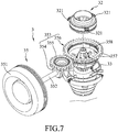
- the grinding mechanism 3 includes a mounting frame 31, first and second grinding members 32, 33 which are mounted on the mounting frame 31 and which are rotatable relative to and cooperate with each other to define a grinding space 30 for receiving coffee beans introduced from the bean container 2, a driven gear 34 which is disposed to couple the second grinding member 33 with the power mechanism 4, and a particle size adjusting unit 35.
- the mounting frame 31 includes a first mounting portion 311 for mounting the first grinding member 32 thereon, a second mounting portion 312 connected to a lateral side of the first mounting portion 311 for mounting the particle size adjusting unit 35 thereon, and a first anchoring member 313 projecting from the first mounting portion 311 toward the locking mechanism 5.
- the first mounting portion 311 has a plurality of key slots 314 spaced apart from each other.
- the first anchoring member 313 has a downwardly extending end portion in a form of a dog structure which has a first leading surface 315 facing and inclined toward the locking mechanism 5, and a first trailing surface 316 extending uprightly from the first leading surface 315.
- the first grinding member 32 is disengageable from the mounting frame 31, and is disposed to surround the second grinding member 33.
- the first grinding member 32 includes a plurality of radially extending keys 321 in a spline engagement with the key slots 314 such that the first grinding member 32 is non-rotatably mounted on the mounting frame 31.
- the particle size adjusting unit 35 has a rotary shaft 352 which is rotatably mounted on the second mounting portion 312 about a horizontal axis and which has an operated end 351 in the form of an adjusting knob that is disposed adjacent to the lateral opening 131 (see FIG. 2 ) for being manually operable, and a bevel gear assembly 353 which interconnects the rotary shaft 352 and the first grinding member 32 to convert a rotational drive of the rotary shaft 352 about the horizontal axis into a rotational drive about an upright axis so as to move the first grinding member 32 along the upright axis .
- the bevel gear assembly 353 includes a first bevel gear 354 coupled to and rotated with the rotary shaft 352 about the horizontal axis, a second bevel gear 355 having a bevel gear portion 3551 which meshes with the first bevel gear 354 and a transition gear portion 3552 which is disposed coaxially with the bevel gear portion 3551, and an adjusting annular seat 356 having an annular toothed portion 357 which meshes with the transition gear portion 3552 to be rotated about the upright axis, and an internally threaded portion 358 which is disposed coaxially with the annular toothed portion 357.
- first grinding member 32 is non-rotatably mounted on the mounting frame 31, and is threadedly engaged with the internally threaded portion 358, rotation of the adjusting annular seat 356 about the upright axis results in movement of the first grinding member 32 along the upright axis so as to vary a size of the grinding space 30 between the first and second grinding members 32, 33.
- the power mechanism 4 is mounted in the accommodation space 120 of the base seat 1, and includes a power motor 41, a reduction gear assembly 42 driven by the power motor 41 to have a rotational drive with a required torque, a driving gear 43 coupled with the reduction gear assembly 42 to receive the rotational drive, and a transmitting gear 44 which meshes with the driving gear 43 and the driven gear 34 of the grinding mechanism 3 so as to transmit a rotational drive received from the transmitting gear 44 to rotate the second grinding member 33 relative to the first grinding member 32.
- the locking mechanism 5 is mounted on the mounting wall 13 of the base seat 1 and opposite to the lateral opening 131 in the horizontal direction to lock the grinding mechanism 3 to the base seat 1.
- the locking mechanism 3 includes a second anchoring member 51, an operated member 52 and a biasing member 53.
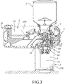
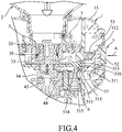
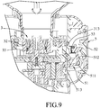
- the second anchoring member 51 is disposed to be movable relative to the base seat 1 between a locking position, as shown in FIG. 4 , where the second anchoring member 51 is engaged with the first anchoring member 313 to retain the grinding mechanism 3 in the mounting space 130, and an unlocking position, as shown in FIG. 9 , where the second anchoring member 51 is disengaged from the first anchoring member 313 so as to permit disengagement of the grinding mechanism 3 from the base seat 1.
- the second anchoring member 51 has a fulcrum portion 511 pivotally mounted on the base seat 511, and a driven portion 512 and an anchoring portion 513 which are disposed at opposite ends of the fulcrum portion 511 and respectively engageable with the operated member 52 and the first anchoring member 313, such that turning of the fulcrum portion 511 by operating the operated member 52 results in disengagement of the anchoring portion513 from the first anchoring member 313 to move the second anchoring member 51 to the unlocking position.
- the anchoring portion 513 has a second trailing surface 514 facing and inclined toward the first anchoring member 313, and a second leading surface 515 extending uprightly from the second trailing surface 514.
- the operated member 52 is movably mounted on the mounting wall 13 and is engaged with the driven portion 512 such that the operated member 52 can be pressed in a direction indicated by arrow (A) of FIG. 4 toward the grinding mechanism 3 to bring the second anchoring member 51 to turn to the unlocking position as shown in FIG. 9 .
- the biasing member 53 is in the form of a biasing spring which is disposed between the second anchoring member 51 and a wall of the base seat 1 to bias the second anchoring member 51 toward the locking position.
- the first micro switch 6 is disposed in the mounting space 130 and adjacent to the second anchoring member 51, and is actuated by the grinding mechanism 3 when mounting of the grinding mechanism 3 on the base seat 1 is completed.
- the second micro switch 7 is disposed in the mounting space 130 and adjacent to the upper opening 132, and is actuated by the bean container 2 when mounting of the bean container 3 on the base seat 1 is completed.
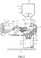
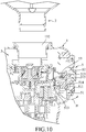
- the grinding mechanism 3 is inserted into the mounting space 130 through the lateral opening 131 (as shown in FIG. 2 ) toward the locking mechanism 5 (as shown in FIG. 10 ) . Then, by slightly turning the second anchoring member 51 in a direction of arrow (B) to lower the anchoring portion 513 so as to pass the first leading surface 315 over the second trailing surface 514, the first trailing surface 316 is brought in abutment against the second leading surface 515, following returning of the second anchoring member 51 to the locking position by means of the biasing member 53, so as to retain the first anchoring member 313 to the second anchoring member 51. In this state, the driven gear 34 meshes with the transmitting gear 44 of the power mechanism 4 in the accommodation space 120, and the first micro switch 6 is actuated.
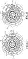
- the annular neck 211 of the bean container 2 is inserted into the mounting space 130 from the upper opening 132 to align the groove 213 with a protrusion 71 of the second micro switch 7 (as shown in FIGS. 14 and 15 ).
- the bean container 2 is not in contact with the second micro switch 7, as shown in FIG. 14 .
- the bean container 2 is turned clockwise to retain thereof to the base seat 1 in a known manner, and to permit the outer surface 212 of the neck 211 to contact the second micro switch 7 for actuating the second micro switch 7, as shown in FIG. 15 .
- a given amount of coffee beans in the containing space 210 of the bean container 2 is transported to the grinding space 30 by gravity.
- the power motor 41 is actuated to rotate the second grinding member 33 relative to the first grinding member 32 for grinding the coffee beans into a powder.
- FIGS. 5 , 6 , 11 and 12 when it is desired to adjust the size of ground powder, the operated end 351 of the particle size adjusting unit 35 is turned about the horizontal axis of the rotary shaft 352 to drive rotation of the adjusting annular seat 356 about the upright axis through the first and second bevel gears 354, 355.
- the first grinding member 32 which is non-rotatably mounted on the mounting frame 31 and which is threadedly engaged with the adjusting annular seat 356, is moved along the upright axis by the rotation of the adjusting annular seat 356 so as to vary a size of the grinding space 30 for adjusting the size of ground powder of the beans.
- FIG. 12 illustrates the state that the first grinding member 32 is lowered to reduce the size of the grinding space 30 from the state shown in FIG. 11 .
- the bean container 2 can be removed from the base seat 1 by counterclockwise turning and upwardly moving the bean container 2 through the upper opening 132. Subsequently, the operated member 52 is pushed by a user to turn the second anchoring member 51 to the unlocking position, as shown in FIG. 9 , where the anchoring portion 513 is disengaged from the first anchoring member 313.
- the user can horizontally move the grinding mechanism 3 along the mounting space 130 to remove the same outwardly of the base seat 1 for cleaning.
- the first grinding member 32 can be disengaged from the mounting frame 31 for facilitating cleaning.
- a cutter (not shown) of the second grinding member 33 can be disposed to be removable therefrom for facilitating cleaning.
- the first and second grinding members 32, 33 can be removed from the base seat 1 to be readily cleaned to prevent the ground powder from remaining in the grinding mechanism 3.
- the grinding mechanism 3 is easy to be assembled and disassembled, and is retained firmly to the base seat 1 by means of the locking mechanism 5.
Landscapes
- Engineering & Computer Science (AREA)
- Food Science & Technology (AREA)
- Mechanical Engineering (AREA)
- Crushing And Grinding (AREA)
Claims (13)
- Bohnenmahlmaschine, die Folgendes umfasst:einen Basissitz (1);einen Bohnenbehälter (2), der zum Enthalten von Bohnen, die zu mahlen sind, am Basissitz (1) montiert ist; undeinen Mahlmechanismus (3), wobei:der Mahlmechanismus (3) entfernbar am Basissitz (1) montiert ist und ein erstes Mahlelement (32) und ein zweites Mahlelement (33) beinhaltet, die relativ zueinander rotierbar sind und miteinander zusammenwirken, um einen Mahlraum (30) zum Aufnehmen der Bohnen, die vom Bohnenbehälter (2) eingeführt werden, zu definieren;der Mahlmechanismus (3) einen Montagerahmen (31) beinhaltet, an dem das erste und das zweite Mahlelement (32, 33) montiert sind, wobei das erste Mahlelement (32) aus dem Montagerahmen (31) ausrückbar ist;dadurch gekennzeichnet, dass die Bohnenmahlmaschine ferner einen Verriegelungsmechanismus (5) umfasst, der am Basissitz (1) angeordnet ist, um den Mahlmechanismus (3) am Basissitz (1) zu verriegeln, wobei der Montagerahmen (31) ein erstes Verankerungselement (313) aufweist, wobei der Verriegelungsmechanismus (3) ein zweites Verankerungselement (51) beinhaltet, das angeordnet ist, zwischen einer Verriegelungsposition, in der das zweite Verankerungselement (51) in das erste Verankerungselement (313) eingerückt ist, um den Mahlmechanismus (3) am Basissitz (1) zu halten, und einer Entriegelungsposition, in der das zweite Verankerungselement (51) aus dem ersten Verankerungselement (313) ausgerückt ist, um das Ausrücken des Mahlmechanismus (3) aus dem Basissitz (1) zu erlauben, relativ zum Basissitz (1) bewegbar zu sein.
- Bohnenmahlmaschine nach Anspruch 1, dadurch gekennzeichnet, dass: der Mahlmechanismus (3) derart am Basissitz (1) montiert ist, dass der Mahlmechanismus (3) in eine horizontale Richtung aus dem Basissitz (1) ausrückbar ist.
- Bohnenmahlmaschine nach Anspruch 1, dadurch gekennzeichnet, dass: der Verriegelungsmechanismus (3) ein Betätigungselement (52) beinhaltet, das angeordnet ist, betätigt zu werden, um das zweite Verankerungselement (51) in die Entriegelungsposition zu bewegen, das zweite Verankerungselement (51) einen Drehpunktabschnitt (511), der schwenkbar am Basissitz (511) montiert ist, sowie einen angetriebenen Abschnitt (512) und einen Verankerungsabschnitt (513), die an gegenüberliegenden Enden des Drehpunktabschnitts (511) angeordnet und jeweils in das Betätigungselement (52) und das erste Verankerungselement (313) einrückbar sind, derart, dass ein Drehen des Drehpunktabschnitts (511) durch Betätigen des Betätigungselements (52) im Ausrücken des Verankerungsabschnitts (513) aus dem ersten Verankerungselement (313) resultiert, beinhaltet.
- Bohnenmahlmaschine nach Anspruch 3, dadurch gekennzeichnet, dass: der Verriegelungsmechanismus (5) ein Vorspannelement (53) beinhaltet, das angeordnet ist, das zweite Verankerungselement (51) zur Verriegelungsposition hin vorzuspannen.
- Bohnenmahlmaschine nach Anspruch 4, dadurch gekennzeichnet, dass: das erste Verankerungselement (313) eine erste vordere Fläche (315), die dem zweiten Verankerungselement (51) zugewandt und zu diesem geneigt ist, und eine erste hintere Fläche (316), die sich von der ersten vorderen Fläche (315) aufrecht erstreckt, aufweist, wobei der Verankerungsabschnitt (513) eine zweite hintere Fläche (514), die dem ersten Verankerungselement (313) zugewandt und zu diesem geneigt ist, und eine zweite vordere Fläche (515) aufweist, die sich von der zweiten hinteren Fläche (514) aufrecht erstreckt, derart, dass die erste hintere Fläche (316) gegen die zweite vordere Fläche (515) in Anschlag gebracht wird, indem die erste vordere Fläche (315) über die zweite hintere Fläche (514) geführt wird, um das erste Verankerungselement (313) am zweiten Verankerungselement (51) zu halten, wenn sich das zweite Verankerungselement (51) in der Verriegelungsposition befindet.
- Bohnenmahlmaschine nach Anspruch 1, dadurch gekennzeichnet, dass: der Basissitz (1) eine Montagewand (13), die dazu ausgelegt ist, einen Montageraum (130) zum Montieren des Mahlmechanismus (3) darin zu definieren, und eine seitliche Öffnung (131) für den Zugang zum Montageraum (130), derart, dass der Mahlmechanismus (3) in eine horizontale Richtung durch die seitliche Öffnung (131) aus dem Montageraum (130) entfernbar ist, beinhaltet.
- Bohnenmahlmaschine nach Anspruch 6, die ferner durch einen Leistungsmechanismus (4) gekennzeichnet ist, wobei der Basissitz (1) ferner eine Basiswand (11) zum Stehen auf einer Fläche, und eine Umgebungswand (12), die sich von der Basiswand (11) nach oben erstreckt und dazu ausgelegt ist, einen Aufnahmeraum (120) zum Montieren des Leistungsmechanismus (4) darin zu definieren, beinhaltet, wobei die Bohnenmahlmaschine ferner einen Verriegelungsmechanismus (5) umfasst, der an der Montagewand (13) montiert und in horizontaler Richtung von der seitlichen Öffnung (131) entfernt ist.
- Bohnenmahlmaschine nach Anspruch 1, dadurch gekennzeichnet, dass: das erste Mahlelement (32) nicht drehbar am Montagerahmen (31) montiert ist und das zweite Mahlelement (33) umgibt, wobei das zweite Mahlelement (33) drehbar am Montagerahmen (31) montiert ist, wobei die Bohnenmahlmaschine ferner einen Leistungsmechanismus (4) umfasst, der am Basissitz (1) montiert ist, wobei der Leistungsmechanismus (4) ein Antriebsrad (43), das angeordnet ist, einen Drehantrieb von einer Leistungsquelle zu empfangen, und ein Übertragungsrad (44), das in das Antriebsrad (43) eingreift, beinhaltet, wobei der Mahlmechanismus (3) ferner ein Abtriebsrad (34) beinhaltet, das in das Übertragungsrad (44) eingreift, um einen Drehantrieb, der vom Übertragungsrad (44) empfangen wird, zu übertragen, um das zweite Mahlelement (33) zu drehen.
- Bohnenmahlmaschine nach Anspruch 1, dadurch gekennzeichnet, dass: der Mahlmechanismus (3) ferner eine Partikelgrößeneinstelleinheit (35) beinhaltet, die angeordnet ist, das erste Mahlelement (32) entlang einer aufrechten Achse relativ zum zweiten Mahlelement (33) zu bewegen, um eine Größe des Mahlraums (30) zu variieren, wobei die Partikelgrößeneinstelleinheit (35) eine Drehwelle (352), die um eine horizontale Achse drehbar am Montagerahmen (31) montiert ist und die ein Betätigungsende (351), um manuell betätigbar zu sein, und eine Kegelradanordnung (353), die die Drehwelle (352) und das erste Mahlelement (32) verbindet, um einen Drehantrieb der Drehwelle (352) um die horizontale Achse in einen Drehantrieb um die aufrechte Achse umzuwandeln, um das erste Mahlelement (32) entlang der aufrechten Achse zu bewegen, aufweist.
- Bohnenmahlmaschine nach Anspruch 9, dadurch gekennzeichnet, dass: die Kegelradanordnung (353) ein erstes Kegelrad (354), das an die Drehwelle (352) gekoppelt ist und sich mit dieser um die horizontale Achse dreht, ein zweites Kegelrad (355) mit einem Kegelradabschnitt (3551), der in das erste Kegelrad (354) eingreift, und einem Übergangsradabschnitt (3552), der koaxial zum Kegelradabschnitt (3551) angeordnet ist, und einen ringförmigen Einstellsitz (356) mit einem ringförmigen Zahnabschnitt (357), der in den Übergangsradabschnitt (3552) eingreift, um um die aufrechte Achse gedreht zu werden, und einem Innengewindeabschnitt (358), der koaxial zum ringförmigen Zahnabschnitt (357) angeordnet ist, beinhaltet, wobei das erste Mahlelement (32) nicht drehbar am Montagerahmen (31) montiert ist und mit dem Innengewindeabschnitt (358) in Gewindeeingriff ist, derart, dass eine Drehung des ringförmigen Einstellsitzes (356) um die aufrechte Achse in einer Bewegung des ersten Mahlelements (32) entlang der aufrechten Achse resultiert.
- Bohnenmahlmaschine nach Anspruch 1, ferner gekennzeichnet durch einen ersten Mikroschalter (6), der am Basissitz (1) angeordnet ist und vom Mahlmechanismus (3) geschaltet wird, wenn die Montage des Mahlmechanismus (3) am Basissitz (1) abgeschlossen ist.
- Bohnenmahlmaschine nach Anspruch 11, dadurch gekennzeichnet, dass: der Bohnenbehälter (2) entfernbar am Basissitz (1) montiert ist, und die ferner einen zweiten Mikroschalter (7) umfasst, der am Basissitz (1) angeordnet ist und vom Bohnenbehälter (3) geschaltet wird, wenn die Montage des Bohnenbehälters (3) am Basissitz (1) abgeschlossen ist.
- Bohnenmahlmaschine nach Anspruch 12, dadurch gekennzeichnet, dass: der Basissitz (1) eine Montagewand (13), die dazu ausgelegt ist, einen Montageraum (130) zum Montieren des Mahlmechanismus (3) darin zu definieren, eine seitliche Öffnung (131) für den Zugang zum Montageraum (130), derart, dass der Mahlmechanismus (3) in eine horizontale Richtung durch die seitliche Öffnung (131) aus dem Montageraum (130) entfernbar ist, und eine obere Öffnung (132), die angeordnet ist, zwischen dem Montageraum (130) und dem Bohnenbehälter (2) in räumlicher Interkommunikation zu sein, beinhaltet.
Applications Claiming Priority (1)
| Application Number | Priority Date | Filing Date | Title |
|---|---|---|---|
| CN201610267932.1A CN107307759B (zh) | 2016-04-27 | 2016-04-27 | 磨豆机 |
Publications (2)
| Publication Number | Publication Date |
|---|---|
| EP3238583A1 EP3238583A1 (de) | 2017-11-01 |
| EP3238583B1 true EP3238583B1 (de) | 2020-03-04 |
Family
ID=58606163
Family Applications (1)
| Application Number | Title | Priority Date | Filing Date |
|---|---|---|---|
| EP17167692.7A Active EP3238583B1 (de) | 2016-04-27 | 2017-04-24 | Maschine zum mahlen von bohnen |
Country Status (3)
| Country | Link |
|---|---|
| US (1) | US20170311759A1 (de) |
| EP (1) | EP3238583B1 (de) |
| CN (1) | CN107307759B (de) |
Families Citing this family (13)
| Publication number | Priority date | Publication date | Assignee | Title |
|---|---|---|---|---|
| CN107049034B (zh) * | 2017-03-23 | 2023-05-16 | 广东百胜图科技有限公司 | 一种磨豆滴落咖啡机 |
| CN107981728B (zh) | 2017-12-26 | 2020-04-14 | 威斯达电器(中山)制造有限公司 | 磨豆装置及磨豆咖啡机 |
| CN108478043B (zh) * | 2018-05-21 | 2024-07-02 | 广东万事泰电器有限公司 | 磨豆机 |
| USD969533S1 (en) * | 2020-09-02 | 2022-11-15 | Blue Sky Innovation Group, Inc. | Food grinder |
| USD968875S1 (en) * | 2020-09-02 | 2022-11-08 | Blue Sky Innovation Group, Inc. | Food grinder |
| USD969532S1 (en) * | 2020-09-02 | 2022-11-15 | Blue Sky Innovation Group, Inc. | Food grinder |
| CN113796747A (zh) * | 2021-11-06 | 2021-12-17 | 中山市欧博尔电器有限公司 | 一种便于清洁的磨豆机 |
| USD992958S1 (en) * | 2021-12-23 | 2023-07-25 | Dongguan Zhen Zhong Kang Precision Transmission Technology Co., Ltd | Noodle squeezer |
| CN116491826B (zh) * | 2022-01-18 | 2025-07-18 | 漳州灿坤实业有限公司 | 研磨机 |
| CN114307813B (zh) * | 2022-01-20 | 2022-09-16 | 贵州电网有限责任公司凯里供电局 | 一种石墨烯复合物防锈剂生产用加工装置 |
| USD1037767S1 (en) * | 2022-07-19 | 2024-08-06 | Mazzer Luigi S.P.A. | Coffee grinder |
| CN222055268U (zh) * | 2024-04-03 | 2024-11-26 | 深圳市盈德精密制造有限公司 | 兼容锥磨盘和平磨盘的磨豆机 |
| CN119586896B (zh) * | 2024-12-13 | 2025-09-19 | 浙江比依电器股份有限公司 | 一种自锁检测式咖啡机豆仓系统 |
Family Cites Families (12)
| Publication number | Priority date | Publication date | Assignee | Title |
|---|---|---|---|---|
| FR895815A (de) * | 1945-02-09 | |||
| AT335263B (de) * | 1975-06-07 | 1977-03-10 | Bosch Siemens Hausgeraete | Kaffeemuhle - insbesondere elektromotorisch angetriebene haushalt-kaffeemuhle |
| US4082234A (en) * | 1977-03-18 | 1978-04-04 | Douglas Hoffman | Milling wheels for small flour mills |
| DE2716253C2 (de) * | 1977-04-13 | 1985-08-22 | Johann Georg Dr.med.dent. 7742 St Georgen Schnitzer | Getreidemühle |
| CN200994735Y (zh) * | 2006-12-27 | 2007-12-26 | 李行 | 咖啡机的研磨装置 |
| CN201197645Y (zh) * | 2008-04-18 | 2009-02-25 | 厦门灿坤实业股份有限公司 | 一种全自动磨豆机 |
| CN202234915U (zh) * | 2011-09-19 | 2012-05-30 | 美的集团有限公司 | 一种咖啡豆研磨机及设有该研磨机的咖啡机 |
| US8944354B2 (en) * | 2011-09-30 | 2015-02-03 | Starbucks Corporation | Apparatus, systems, and methods for grinding a material |
| CN202821015U (zh) * | 2012-09-20 | 2013-03-27 | 新宝基电器(深圳)有限公司 | 一种咖啡豆研磨机 |
| CN203458257U (zh) * | 2013-07-19 | 2014-03-05 | 宁波厨聚厨房科技有限公司 | 调料研磨器组件 |
| CN203914627U (zh) * | 2014-01-21 | 2014-11-05 | 九阳股份有限公司 | 一种卧式研磨器 |
| CN205164818U (zh) * | 2015-11-11 | 2016-04-20 | 陈旭 | 一种五谷杂粮自动磨粉机 |
-
2016
- 2016-04-27 CN CN201610267932.1A patent/CN107307759B/zh active Active
-
2017
- 2017-04-17 US US15/488,851 patent/US20170311759A1/en not_active Abandoned
- 2017-04-24 EP EP17167692.7A patent/EP3238583B1/de active Active
Non-Patent Citations (1)
| Title |
|---|
| None * |
Also Published As
| Publication number | Publication date |
|---|---|
| EP3238583A1 (de) | 2017-11-01 |
| CN107307759A (zh) | 2017-11-03 |
| CN107307759B (zh) | 2020-07-21 |
| US20170311759A1 (en) | 2017-11-02 |
Similar Documents
| Publication | Publication Date | Title |
|---|---|---|
| EP3238583A1 (de) | Maschine zum mahlen von bohnen | |
| US3612414A (en) | Coffee mill | |
| US7637447B2 (en) | Dual condiment grinder | |
| JP5097005B2 (ja) | 香料破砕グラインダー及びその自動開閉制御装置 | |
| US9303433B2 (en) | Transmission mechanism of a lock assembly | |
| US20210023411A1 (en) | Kettlebell | |
| EP2962610B1 (de) | Lebensmittelverarbeitungsvorrichtung und -verfahren | |
| US9114499B2 (en) | Working tool | |
| US20030071471A1 (en) | Electric door lock | |
| CN102961063A (zh) | 用于食品处理器的盖子 | |
| US5533801A (en) | Electrically operated hand mixer including an attachment | |
| US10939783B2 (en) | Food processor lid | |
| CN102510732B (zh) | 加工和烹饪食品的装置 | |
| US6832500B1 (en) | Electric door lock | |
| US9693657B2 (en) | Spice mill | |
| US7380737B2 (en) | Electric seasoning mill | |
| EP2238882A2 (de) | Pfeffermühle | |
| US8011609B2 (en) | Pepper mill | |
| EP1839545B1 (de) | Gewürzmühle | |
| JP4200313B2 (ja) | 粉挽き機 | |
| EP4084655A1 (de) | Halbautomatische maschine zum zerkleinern und sammeln von aussen gefrorenen lebensmittelsubstanzen für eine anschliessende lebensmittelverwendung dieser lebensmittelsubstanzen | |
| CA2618246A1 (en) | Electric lock that can be operated electrically or manually | |
| KR20170035759A (ko) | 동력 전달 구조를 갖는 식품 가공 장치 | |
| KR20150141849A (ko) | 자동회전 머그컵 | |
| KR20180119855A (ko) | 동력 전달 구조를 갖는 식품 가공 장치 |
Legal Events
| Date | Code | Title | Description |
|---|---|---|---|
| PUAI | Public reference made under article 153(3) epc to a published international application that has entered the european phase |
Free format text: ORIGINAL CODE: 0009012 |
|
| STAA | Information on the status of an ep patent application or granted ep patent |
Free format text: STATUS: THE APPLICATION HAS BEEN PUBLISHED |
|
| AK | Designated contracting states |
Kind code of ref document: A1 Designated state(s): AL AT BE BG CH CY CZ DE DK EE ES FI FR GB GR HR HU IE IS IT LI LT LU LV MC MK MT NL NO PL PT RO RS SE SI SK SM TR |
|
| AX | Request for extension of the european patent |
Extension state: BA ME |
|
| STAA | Information on the status of an ep patent application or granted ep patent |
Free format text: STATUS: REQUEST FOR EXAMINATION WAS MADE |
|
| 17P | Request for examination filed |
Effective date: 20180430 |
|
| RBV | Designated contracting states (corrected) |
Designated state(s): AL AT BE BG CH CY CZ DE DK EE ES FI FR GB GR HR HU IE IS IT LI LT LU LV MC MK MT NL NO PL PT RO RS SE SI SK SM TR |
|
| RIC1 | Information provided on ipc code assigned before grant |
Ipc: A47J 42/06 20060101AFI20190709BHEP |
|
| GRAP | Despatch of communication of intention to grant a patent |
Free format text: ORIGINAL CODE: EPIDOSNIGR1 |
|
| STAA | Information on the status of an ep patent application or granted ep patent |
Free format text: STATUS: GRANT OF PATENT IS INTENDED |
|
| INTG | Intention to grant announced |
Effective date: 20190916 |
|
| RIN1 | Information on inventor provided before grant (corrected) |
Inventor name: XUE, ZHIQIANG Inventor name: LIU, SHANGKUN Inventor name: ZHANG, YANXIANG Inventor name: CHEN, HONGHAI |
|
| GRAS | Grant fee paid |
Free format text: ORIGINAL CODE: EPIDOSNIGR3 |
|
| GRAA | (expected) grant |
Free format text: ORIGINAL CODE: 0009210 |
|
| STAA | Information on the status of an ep patent application or granted ep patent |
Free format text: STATUS: THE PATENT HAS BEEN GRANTED |
|
| AK | Designated contracting states |
Kind code of ref document: B1 Designated state(s): AL AT BE BG CH CY CZ DE DK EE ES FI FR GB GR HR HU IE IS IT LI LT LU LV MC MK MT NL NO PL PT RO RS SE SI SK SM TR |
|
| REG | Reference to a national code |
Ref country code: GB Ref legal event code: FG4D |
|
| REG | Reference to a national code |
Ref country code: CH Ref legal event code: EP |
|
| REG | Reference to a national code |
Ref country code: AT Ref legal event code: REF Ref document number: 1239419 Country of ref document: AT Kind code of ref document: T Effective date: 20200315 |
|
| REG | Reference to a national code |
Ref country code: DE Ref legal event code: R096 Ref document number: 602017012454 Country of ref document: DE |
|
| REG | Reference to a national code |
Ref country code: IE Ref legal event code: FG4D |
|
| PG25 | Lapsed in a contracting state [announced via postgrant information from national office to epo] |
Ref country code: FI Free format text: LAPSE BECAUSE OF FAILURE TO SUBMIT A TRANSLATION OF THE DESCRIPTION OR TO PAY THE FEE WITHIN THE PRESCRIBED TIME-LIMIT Effective date: 20200304 Ref country code: RS Free format text: LAPSE BECAUSE OF FAILURE TO SUBMIT A TRANSLATION OF THE DESCRIPTION OR TO PAY THE FEE WITHIN THE PRESCRIBED TIME-LIMIT Effective date: 20200304 Ref country code: NO Free format text: LAPSE BECAUSE OF FAILURE TO SUBMIT A TRANSLATION OF THE DESCRIPTION OR TO PAY THE FEE WITHIN THE PRESCRIBED TIME-LIMIT Effective date: 20200604 |
|
| PGFP | Annual fee paid to national office [announced via postgrant information from national office to epo] |
Ref country code: FR Payment date: 20200331 Year of fee payment: 4 Ref country code: DE Payment date: 20200417 Year of fee payment: 4 |
|
| REG | Reference to a national code |
Ref country code: NL Ref legal event code: MP Effective date: 20200304 |
|
| PG25 | Lapsed in a contracting state [announced via postgrant information from national office to epo] |
Ref country code: LV Free format text: LAPSE BECAUSE OF FAILURE TO SUBMIT A TRANSLATION OF THE DESCRIPTION OR TO PAY THE FEE WITHIN THE PRESCRIBED TIME-LIMIT Effective date: 20200304 Ref country code: SE Free format text: LAPSE BECAUSE OF FAILURE TO SUBMIT A TRANSLATION OF THE DESCRIPTION OR TO PAY THE FEE WITHIN THE PRESCRIBED TIME-LIMIT Effective date: 20200304 Ref country code: BG Free format text: LAPSE BECAUSE OF FAILURE TO SUBMIT A TRANSLATION OF THE DESCRIPTION OR TO PAY THE FEE WITHIN THE PRESCRIBED TIME-LIMIT Effective date: 20200604 Ref country code: GR Free format text: LAPSE BECAUSE OF FAILURE TO SUBMIT A TRANSLATION OF THE DESCRIPTION OR TO PAY THE FEE WITHIN THE PRESCRIBED TIME-LIMIT Effective date: 20200605 Ref country code: HR Free format text: LAPSE BECAUSE OF FAILURE TO SUBMIT A TRANSLATION OF THE DESCRIPTION OR TO PAY THE FEE WITHIN THE PRESCRIBED TIME-LIMIT Effective date: 20200304 |
|
| PGFP | Annual fee paid to national office [announced via postgrant information from national office to epo] |
Ref country code: IT Payment date: 20200430 Year of fee payment: 4 |
|
| REG | Reference to a national code |
Ref country code: LT Ref legal event code: MG4D |
|
| PG25 | Lapsed in a contracting state [announced via postgrant information from national office to epo] |
Ref country code: NL Free format text: LAPSE BECAUSE OF FAILURE TO SUBMIT A TRANSLATION OF THE DESCRIPTION OR TO PAY THE FEE WITHIN THE PRESCRIBED TIME-LIMIT Effective date: 20200304 |
|
| PG25 | Lapsed in a contracting state [announced via postgrant information from national office to epo] |
Ref country code: SM Free format text: LAPSE BECAUSE OF FAILURE TO SUBMIT A TRANSLATION OF THE DESCRIPTION OR TO PAY THE FEE WITHIN THE PRESCRIBED TIME-LIMIT Effective date: 20200304 Ref country code: EE Free format text: LAPSE BECAUSE OF FAILURE TO SUBMIT A TRANSLATION OF THE DESCRIPTION OR TO PAY THE FEE WITHIN THE PRESCRIBED TIME-LIMIT Effective date: 20200304 Ref country code: SK Free format text: LAPSE BECAUSE OF FAILURE TO SUBMIT A TRANSLATION OF THE DESCRIPTION OR TO PAY THE FEE WITHIN THE PRESCRIBED TIME-LIMIT Effective date: 20200304 Ref country code: IS Free format text: LAPSE BECAUSE OF FAILURE TO SUBMIT A TRANSLATION OF THE DESCRIPTION OR TO PAY THE FEE WITHIN THE PRESCRIBED TIME-LIMIT Effective date: 20200704 Ref country code: ES Free format text: LAPSE BECAUSE OF FAILURE TO SUBMIT A TRANSLATION OF THE DESCRIPTION OR TO PAY THE FEE WITHIN THE PRESCRIBED TIME-LIMIT Effective date: 20200304 Ref country code: PT Free format text: LAPSE BECAUSE OF FAILURE TO SUBMIT A TRANSLATION OF THE DESCRIPTION OR TO PAY THE FEE WITHIN THE PRESCRIBED TIME-LIMIT Effective date: 20200729 Ref country code: CZ Free format text: LAPSE BECAUSE OF FAILURE TO SUBMIT A TRANSLATION OF THE DESCRIPTION OR TO PAY THE FEE WITHIN THE PRESCRIBED TIME-LIMIT Effective date: 20200304 Ref country code: LT Free format text: LAPSE BECAUSE OF FAILURE TO SUBMIT A TRANSLATION OF THE DESCRIPTION OR TO PAY THE FEE WITHIN THE PRESCRIBED TIME-LIMIT Effective date: 20200304 Ref country code: RO Free format text: LAPSE BECAUSE OF FAILURE TO SUBMIT A TRANSLATION OF THE DESCRIPTION OR TO PAY THE FEE WITHIN THE PRESCRIBED TIME-LIMIT Effective date: 20200304 |
|
| REG | Reference to a national code |
Ref country code: AT Ref legal event code: MK05 Ref document number: 1239419 Country of ref document: AT Kind code of ref document: T Effective date: 20200304 |
|
| REG | Reference to a national code |
Ref country code: CH Ref legal event code: PL |
|
| REG | Reference to a national code |
Ref country code: DE Ref legal event code: R097 Ref document number: 602017012454 Country of ref document: DE |
|
| PG25 | Lapsed in a contracting state [announced via postgrant information from national office to epo] |
Ref country code: MC Free format text: LAPSE BECAUSE OF FAILURE TO SUBMIT A TRANSLATION OF THE DESCRIPTION OR TO PAY THE FEE WITHIN THE PRESCRIBED TIME-LIMIT Effective date: 20200304 |
|
| PLBE | No opposition filed within time limit |
Free format text: ORIGINAL CODE: 0009261 |
|
| STAA | Information on the status of an ep patent application or granted ep patent |
Free format text: STATUS: NO OPPOSITION FILED WITHIN TIME LIMIT |
|
| PG25 | Lapsed in a contracting state [announced via postgrant information from national office to epo] |
Ref country code: CH Free format text: LAPSE BECAUSE OF NON-PAYMENT OF DUE FEES Effective date: 20200430 Ref country code: AT Free format text: LAPSE BECAUSE OF FAILURE TO SUBMIT A TRANSLATION OF THE DESCRIPTION OR TO PAY THE FEE WITHIN THE PRESCRIBED TIME-LIMIT Effective date: 20200304 Ref country code: DK Free format text: LAPSE BECAUSE OF FAILURE TO SUBMIT A TRANSLATION OF THE DESCRIPTION OR TO PAY THE FEE WITHIN THE PRESCRIBED TIME-LIMIT Effective date: 20200304 Ref country code: LI Free format text: LAPSE BECAUSE OF NON-PAYMENT OF DUE FEES Effective date: 20200430 Ref country code: LU Free format text: LAPSE BECAUSE OF NON-PAYMENT OF DUE FEES Effective date: 20200424 |
|
| REG | Reference to a national code |
Ref country code: BE Ref legal event code: MM Effective date: 20200430 |
|
| 26N | No opposition filed |
Effective date: 20201207 |
|
| PG25 | Lapsed in a contracting state [announced via postgrant information from national office to epo] |
Ref country code: PL Free format text: LAPSE BECAUSE OF FAILURE TO SUBMIT A TRANSLATION OF THE DESCRIPTION OR TO PAY THE FEE WITHIN THE PRESCRIBED TIME-LIMIT Effective date: 20200304 Ref country code: SI Free format text: LAPSE BECAUSE OF FAILURE TO SUBMIT A TRANSLATION OF THE DESCRIPTION OR TO PAY THE FEE WITHIN THE PRESCRIBED TIME-LIMIT Effective date: 20200304 Ref country code: BE Free format text: LAPSE BECAUSE OF NON-PAYMENT OF DUE FEES Effective date: 20200430 |
|
| PG25 | Lapsed in a contracting state [announced via postgrant information from national office to epo] |
Ref country code: IE Free format text: LAPSE BECAUSE OF NON-PAYMENT OF DUE FEES Effective date: 20200424 |
|
| REG | Reference to a national code |
Ref country code: DE Ref legal event code: R119 Ref document number: 602017012454 Country of ref document: DE |
|
| GBPC | Gb: european patent ceased through non-payment of renewal fee |
Effective date: 20210424 |
|
| PG25 | Lapsed in a contracting state [announced via postgrant information from national office to epo] |
Ref country code: GB Free format text: LAPSE BECAUSE OF NON-PAYMENT OF DUE FEES Effective date: 20210424 Ref country code: FR Free format text: LAPSE BECAUSE OF NON-PAYMENT OF DUE FEES Effective date: 20210430 Ref country code: DE Free format text: LAPSE BECAUSE OF NON-PAYMENT OF DUE FEES Effective date: 20211103 |
|
| PG25 | Lapsed in a contracting state [announced via postgrant information from national office to epo] |
Ref country code: TR Free format text: LAPSE BECAUSE OF FAILURE TO SUBMIT A TRANSLATION OF THE DESCRIPTION OR TO PAY THE FEE WITHIN THE PRESCRIBED TIME-LIMIT Effective date: 20200304 Ref country code: MT Free format text: LAPSE BECAUSE OF FAILURE TO SUBMIT A TRANSLATION OF THE DESCRIPTION OR TO PAY THE FEE WITHIN THE PRESCRIBED TIME-LIMIT Effective date: 20200304 Ref country code: CY Free format text: LAPSE BECAUSE OF FAILURE TO SUBMIT A TRANSLATION OF THE DESCRIPTION OR TO PAY THE FEE WITHIN THE PRESCRIBED TIME-LIMIT Effective date: 20200304 |
|
| PG25 | Lapsed in a contracting state [announced via postgrant information from national office to epo] |
Ref country code: MK Free format text: LAPSE BECAUSE OF FAILURE TO SUBMIT A TRANSLATION OF THE DESCRIPTION OR TO PAY THE FEE WITHIN THE PRESCRIBED TIME-LIMIT Effective date: 20200304 Ref country code: AL Free format text: LAPSE BECAUSE OF FAILURE TO SUBMIT A TRANSLATION OF THE DESCRIPTION OR TO PAY THE FEE WITHIN THE PRESCRIBED TIME-LIMIT Effective date: 20200304 |
|
| PG25 | Lapsed in a contracting state [announced via postgrant information from national office to epo] |
Ref country code: IT Free format text: LAPSE BECAUSE OF NON-PAYMENT OF DUE FEES Effective date: 20200424 |
|
| PG25 | Lapsed in a contracting state [announced via postgrant information from national office to epo] |
Ref country code: IT Free format text: LAPSE BECAUSE OF NON-PAYMENT OF DUE FEES Effective date: 20200424 |
|
| PGRI | Patent reinstated in contracting state [announced from national office to epo] |
Ref country code: IT Effective date: 20200430 |
|
| PG25 | Lapsed in a contracting state [announced via postgrant information from national office to epo] |
Ref country code: IT Free format text: LAPSE BECAUSE OF NON-PAYMENT OF DUE FEES Effective date: 20210424 |