EP3238526A1 - Harvesting machine with a pick-up device - Google Patents
Harvesting machine with a pick-up device Download PDFInfo
- Publication number
- EP3238526A1 EP3238526A1 EP17159474.0A EP17159474A EP3238526A1 EP 3238526 A1 EP3238526 A1 EP 3238526A1 EP 17159474 A EP17159474 A EP 17159474A EP 3238526 A1 EP3238526 A1 EP 3238526A1
- Authority
- EP
- European Patent Office
- Prior art keywords
- conveying
- crop
- section
- conveyor
- sections
- Prior art date
- Legal status (The legal status is an assumption and is not a legal conclusion. Google has not performed a legal analysis and makes no representation as to the accuracy of the status listed.)
- Granted
Links
- 238000003306 harvesting Methods 0.000 title claims abstract description 20
- 238000009827 uniform distribution Methods 0.000 description 9
- 238000009826 distribution Methods 0.000 description 5
- 230000000694 effects Effects 0.000 description 4
- 239000000463 material Substances 0.000 description 4
- 238000003825 pressing Methods 0.000 description 4
- 230000006978 adaptation Effects 0.000 description 3
- 238000005520 cutting process Methods 0.000 description 3
- 238000011161 development Methods 0.000 description 3
- 230000018109 developmental process Effects 0.000 description 3
- 239000010902 straw Substances 0.000 description 3
- 230000005540 biological transmission Effects 0.000 description 2
- 230000001788 irregular Effects 0.000 description 2
- 238000004519 manufacturing process Methods 0.000 description 2
- 238000003860 storage Methods 0.000 description 2
- 244000025254 Cannabis sativa Species 0.000 description 1
- 241001124569 Lycaenidae Species 0.000 description 1
- 230000006835 compression Effects 0.000 description 1
- 238000007906 compression Methods 0.000 description 1
- 239000004459 forage Substances 0.000 description 1
- 239000004463 hay Substances 0.000 description 1
- 210000000056 organ Anatomy 0.000 description 1
- 230000001105 regulatory effect Effects 0.000 description 1
- 239000004460 silage Substances 0.000 description 1
- 239000002689 soil Substances 0.000 description 1
Images

Classifications
-
- A—HUMAN NECESSITIES
- A01—AGRICULTURE; FORESTRY; ANIMAL HUSBANDRY; HUNTING; TRAPPING; FISHING
- A01D—HARVESTING; MOWING
- A01D89/00—Pick-ups for loaders, chaff-cutters, balers, field-threshers, or the like, i.e. attachments for picking-up hay or the like field crops
- A01D89/006—Accessories
- A01D89/008—Devices cooperating with the pick-up
-
- A—HUMAN NECESSITIES
- A01—AGRICULTURE; FORESTRY; ANIMAL HUSBANDRY; HUNTING; TRAPPING; FISHING
- A01D—HARVESTING; MOWING
- A01D41/00—Combines, i.e. harvesters or mowers combined with threshing devices
- A01D41/10—Field threshers with windrow pick-up apparatus
-
- A—HUMAN NECESSITIES
- A01—AGRICULTURE; FORESTRY; ANIMAL HUSBANDRY; HUNTING; TRAPPING; FISHING
- A01D—HARVESTING; MOWING
- A01D41/00—Combines, i.e. harvesters or mowers combined with threshing devices
- A01D41/12—Details of combines
- A01D41/14—Mowing tables
-
- A—HUMAN NECESSITIES
- A01—AGRICULTURE; FORESTRY; ANIMAL HUSBANDRY; HUNTING; TRAPPING; FISHING
- A01D—HARVESTING; MOWING
- A01D89/00—Pick-ups for loaders, chaff-cutters, balers, field-threshers, or the like, i.e. attachments for picking-up hay or the like field crops
- A01D89/006—Accessories
-
- A—HUMAN NECESSITIES
- A01—AGRICULTURE; FORESTRY; ANIMAL HUSBANDRY; HUNTING; TRAPPING; FISHING
- A01F—PROCESSING OF HARVESTED PRODUCE; HAY OR STRAW PRESSES; DEVICES FOR STORING AGRICULTURAL OR HORTICULTURAL PRODUCE
- A01F15/00—Baling presses for straw, hay or the like
- A01F15/08—Details
- A01F15/10—Feeding devices for the crop material e.g. precompression devices
Definitions
- the invention relates to a harvester, in particular a baler or a loader wagon, for agricultural crop according to the preamble of claim 1.
- Harvesters such as agricultural balers or self-loading wagons are used for receiving and further processing or transporting crops, such as straw and / or leaf material in the form of straw, hay or silage, which has been stored on a field in the form of a swath.
- crops such as straw and / or leaf material in the form of straw, hay or silage, which has been stored on a field in the form of a swath.
- a so-called pickup which comprises, for example, a pick-up drum provided with tines.
- the crop can be picked up by the tines from the ground and transported for example to a downstream conveying rotor and / or crop channel.
- the receiving device and the collecting drum usually have a significantly greater width than the subsequent conveyor rotor and / or Erntegutkanal, are arranged on the receiving devices often parallel to the collecting drum, rotatable screw conveyors, which cause a merging of the picked crop to the center of the recording device .
- the augers can also, in particular transversely to a conveying direction of the crop, a more uniform distribution of the crop before being fed to the conveyor rotor and / or Erntegutkanal be improved. This is particularly advantageous in a harvester such as a baler, since the quality of the bale can be improved by a more uniform distribution of the crop over a width of the crop channel.
- a baler with a receiving device for receiving crop by means of a receiving drum known.
- the receiving device has in each case above the ends of the receiving drum on a screw auger stub to support a promotion of the crop to the center of the receiving device out.
- a feed roller provided, which end screw conveyor thread, by which also a merging of the crop is to be effected.
- the feed roller has in a central portion of a plurality of conveyor bars, which allows a promotion of the crop to a conveyor rotor and / or a crop channel out.
- An adaptation to different crops can be done by manually attaching enlargement plates on the conveyor bars.
- An agricultural harvester with a crop picking device wherein the picking device comprises at least one drivable picking drum for picking up crop and at least one drivable conveying member, the conveying member having radially outwardly conveying elements for conveying the crop to a conveying rotor and / or crop channel.
- the conveying member has at least two conveying sections, which are formed independently rotatable and driven.
- the conveyor with at least two independent conveyor sections according to the invention allows a different design of the respective conveyor sections for the separate and different influence on the promotion of the crop.
- a conveying section can effect a conveying of the crop transversely to the longitudinal direction of the harvesting machine and another conveying section a conveying in the longitudinal direction.
- the independently rotatable and drivable conveyor sections a simple adaptation to different crops and / or different crop conditions with little effort possible, so that the uniform distribution of the crop can be ensured even with different crop and / or changing crop conditions.
- the at least two conveyor sections are arranged coaxially with each other. This allows a space-saving arrangement of the conveyor sections, for example, side by side, whereby different conveying properties of the respective conveyor sections, such as a promotion transverse to the longitudinal direction or in the longitudinal direction, can be combined.
- the conveying member has three conveying sections, wherein a first conveying section is arranged substantially in the center of the conveying member and / or the receiving device, and a second and third conveying section are each arranged on the outside of the first conveying section.
- the second and third conveyor section can thereby convey the crop material substantially transversely to the longitudinal direction to the first conveyor section, wherein the first conveyor section can further convey the crop to a conveyor rotor and / or a crop channel.
- the first conveyor section has a
- the first conveyor section has a drive shaft which is rotatably mounted on each end, in particular in the receiving device, wherein the outer, in particular second and third, conveyor sections are rotatably arranged on the drive shaft.
- a plurality of conveyor sections may be rotatably arranged on one or both sides of the first conveyor section.
- the rotatably arranged conveying sections may be rotatable together with the drive shaft or rotatable relative to the drive shaft.
- the outer conveyor sections in particular the second and third conveyor section, with different speeds and / or in different directions of rotation can be driven.
- different conveying properties of the individual conveyor sections can be better utilized and coordinated with each other. This has the advantage that even with an irregular swath and / or an off-center recording of the crop, a uniform distribution of the crop prior to feeding to the conveyor rotor and / or the crop channel can be made possible.
- conveying sections arranged on the outside, in particular the second and third conveying sections can be driven together by a rotatable connecting shaft.
- the outer, in particular end, conveyor sections, for example, the second and third conveyor section are driven by a common drive unit.
- the speeds and directions of rotation of the respective conveyor sections can be operable for example by means of a transmission in a fixed or variable ratio to each other.
- a rotational speed and / or a direction of rotation of a conveying section can be regulated in each case as a function of at least one machine parameter and / or one operating parameter.
- At least one first drive unit is provided for driving the conveying member.
- certain or all conveyor sections for example also via a connecting shaft, can be driven efficiently.
- conveying sections can be formed separately drivable, whereby the production and / or distribution of the crop can be further improved.
- At least one, in particular the first, conveying section and / or at least one conveying element is designed to be interchangeable.
- the conveying properties of your conveyor section and / or the conveyor elements can be changed, whereby these can be advantageously adapted, for example, to different crop types and / or harvest conditions.
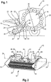
- a harvester in the form of a baler is shown in a schematic side view.
- a harvester 10 may be in the form of a press, a baler such as a round bale or square baler, a loading wagon, a forage harvester or a combine harvester.
- balers in the form of presses, in particular balers, or loader wagons are usually pulled by a towing vehicle such as a tractor (not shown) and supplied with energy via a drive shaft which can be coupled thereto for driving the conveying and processing devices.
- the illustrated baler 10 takes in harvesting on the field soil lying crop, for example, the swath deposited straw or grass, and processed this to a pressed chamber 12 in a bale 14, which is ejected after completion of the baler 10.
- the conveying direction of the crop from the collecting drum 18, for example, to the pressing chamber 12 essentially corresponds to a longitudinal direction of the harvesting machine 10.
- the crop is first fed to a conveying element 22 arranged downstream of the collecting drum 18.
- the conveying member 22 extends, as well as the collecting drum 18, substantially over an entire width of the receiving device 16.
- the conveying member 22 is rotatably mounted for rotation about an axis of rotation 24 and the crop from an original receiving width of the collecting drum 18 to a smaller width merge in the conveying direction downstream crop channel 26.
- the conveyor organ can arrange the crop to be arranged downstream in the conveying direction, and in particular to feed the crop channel 26 and feed it into this conveying rotor 28.
- the conveying rotor 28 is rotatably mounted about a rotor axis 30 and has a plurality of mutually spaced, star-shaped rotor elements 32, which act in the Erntegutkanal 26 to promote the crop, for example, for compression in the direction of the pressing chamber 12.
- a Gutleitelement 34 in the form of a bent sheet, which limits the Erntegutkanal 26 over its entire width down.
- a cutting device 36 is arranged, which has a plurality of cutting elements has, which can be formed hineinschwenkbar at least partially into the Erntegutkanal 26 for comminuting the crop by the Gutleitelement 34.
- the cutting device 36 is arranged substantially press chamber side of the conveyor rotor 28. The comminuted crop is then fed to the pressing chamber 12, which is formed within a housing 38 of the baler 10 by circularly arranged and drivable press rollers 40.
- the conveying member 22 has a first conveying section 42, which is arranged substantially centrally of the receiving device 16.
- the first conveying section 42 can essentially have a width corresponding to the crop channel 26 and / or conveying rotor 28.
- a second conveying section 44 and a third conveying section 46 are arranged, in each case at one end.
- the second conveying portion 44 and the third conveying portion 46 are arranged coaxially with the first conveying portion 42 along the rotation axis 24 and rotatably supported thereabout.
- first conveying section 42 may be designed for conveying the crop along the longitudinal axis of the harvesting machine 10, in particular towards a conveying rotor 28.
- second conveying section 44 and the third conveying section 46 may be designed to convey the crop substantially transversely to the longitudinal direction of the harvesting machine 10 in order to combine the crop with the receiving width and to feed the first conveying section 42.
- a conveying section 42, 44, 46 each have at least one conveying element 48.
- conveying elements 48 are distributed radially on the outside, in particular along its circumference, on the conveying section 42, 44, 46.
- the conveying elements 48 may be detachably connected to the conveying section 42, 44, 46.
- the conveying property of a conveying section 42, 44, 46 can be influenced.
- the first conveying section 42 may have a plurality radially outside and over the circumference have distributed conveying elements 48, which are formed substantially in the form of flat conveying elements 50.
- flat conveying elements 50 are to be understood as conveying elements 48, 50 which have a surface for conveying the crop material which is essentially parallel to the axis of rotation 24, in particular in the case of a rotation of the conveying section 42 , 44, 46 to effect conveying of the crop material substantially in the longitudinal direction of the harvesting machine 10.
- conveying elements 48, 50 of the first conveyor section 42 are formed substantially plate-shaped in particular with a radially outwardly formed, end-side bend.
- the second and third conveying sections 44, 46 which are intended essentially to convey the crop transversely to the longitudinal direction of the harvesting machine 10, can each have on their circumference one or more conveying elements 48 arranged radially on the outside, which are designed substantially in the form of angled conveying elements 52.
- angled conveyor elements 52 are in the context of the invention, for example, helical or paddle-like design, conveying elements 48, 52 to understand which have a surface for conveying the crop, which is formed substantially at an angle to the axis of rotation 24, in particular to a rotation of the Conveying section 42, 44, 46 to effect a promotion of the crop substantially transverse to the longitudinal direction of the harvester 10.
- Angled conveying elements 52 of different conveying sections 44, 46 can be designed such that, with the same direction of rotation of the conveying sections 44, 46, the crop is moved in each case to the first conveying section 42.
- Spirally-shaped conveying elements 48, 52, for example of the second and third conveying section 44, 46, can be designed to promote or counteract each other.
- the collecting drum 18 and the conveying member 22 are each rotatably arranged between two side members 54.
- the conveyor sections 42, 44, 46 may be designed to be rotatable and / or drivable together or independently of each other.
- a rotational speed and / or direction of rotation of the respective conveying sections 42, 44, 46 can be individually and grouped controllable and controllable, for example by a control unit (not shown) adjustable.
- a speed and / or a The direction of rotation of the first conveying section 42 can be adjustable independently of a rotational speed and / or rotational direction of the second and / or third conveying section 44, 46.
- a rotational speed and / or a direction of rotation of one or more conveying sections 42, 44, 46 can be set as a function of at least one machine parameter Pm and / or an operating parameter Pb in order to achieve optimal distribution and conveying of the crop.
- An operating parameter is, for example, the type and / or a specific property of the crop to be processed, a conveying speed of the crop in the Erntegutkanal, a swath geometry, and / or a driving speed of the harvester, which affects the amount of crops picked.
- a machine parameter can be, for example, the type and / or configuration of the conveyor sections and / or the conveyor elements, a rotational speed of the collecting drum 18, the conveyor rotor 28 and / or a degree of filling of the pressing chamber 12, an available drive power for the receiving device 16 and / or the conveyor rotor 20 be.
- an adjustment of the rotational speed of the conveying sections 42, 44, 46 as a function of the direction of rotation of the conveying sections 42, 44, 46 can be used as the machine parameter Pm.
- a receiving device 14 is shown in a cut along the axis of rotation 24 front view.
- the first conveying section 42 has a drive shaft 56, which is rotatably mounted at the ends in each case in a side element 54 of the receiving device 16.
- the first conveying section 42 is formed integrally with the drive shaft 56. It is also conceivable, however, a releasable connection of the first conveyor section 42 with the drive shaft 56.
- On both sides of the The first conveying section 42, the second and the third conveying section 44, 46 rotatably mounted on the drive shaft 56, wherein the second and third conveying section 44, 46 are arranged independently rotatably on the drive shaft 56, and in particular are sleeve-shaped.
- the conveyor sections 42, 44, 46 each have conveying elements 48, 52, which are formed spirally. During normal operation, the conveying elements 48, 52 convey the picked crop to the first conveying section 42 and to the crop channel (not shown).
- the conveying elements 48, 52 of the first conveying section 42 are designed in such a way that the spiral conveying elements 48, 52 in normal operation convey towards the center of the first conveying section 42 and thereby meet the spirals in the center.
- the drive shaft 56 can be driven via a first drive unit 58.
- the second and third conveyor sections 44, 46 are each externally driven by a second drive unit 60 via a connecting shaft 62.
- the second and third conveyor sections 44, 46 may be operable via a transmission (not shown) with different speeds and / or directions of rotation.
- hydraulic and / or electric drives can be used as drive units 58, 60.
- a rear wall 64 is respectively arranged, which at the back of the receiving device 16 at least partially forms a boundary through which the transverse promotion of the crop to the first conveyor section 42 can be supported.
- Fig. 4 is the in Fig. 3 illustrated receiving device 16 shown in a perspective view.
- the alternative, helical configuration of the angled conveying elements 48, 52 is shown.
- the conveying elements 48, 52 of the first conveying section 42 are spirally formed such that they form opposing spirals, which meet in the middle of the first conveying section 42, and in particular are formed in a double spiral shape.
- the side elements 54 are at least partially covered on the outside by means of side covers 66, by means of which the drive units 58, 60 are concealable.
Landscapes
- Life Sciences & Earth Sciences (AREA)
- Environmental Sciences (AREA)
- Harvesting Machines For Specific Crops (AREA)
Abstract
Eine landwirtschaftliche Erntemaschine (10) umfasst eine Aufnahmevorrichtung (16) für landwirtschaftliches Erntegut, wobei die Aufnahmevorrichtung (16) mindestens eine antreibbare Aufsammeltrommel (18) zum Aufnehmen von Erntegut und mindestens ein antreibbares Förderorgan (22) aufweist, wobei das Förderorgan (22) radial außenseitig Förderelemente (48, 50, 52) aufweist, um das Erntegut zu einem Förderrotor (28) und/oder einem Erntegutkanal (26) zu fördern. Gemäß der Erfindung weist das Förderorgan (22) mindestens zwei Förderabschnitte (42, 44, 46) auf, welche unabhängig voneinander drehbar und antreibbar ausgebildet sind.An agricultural harvesting machine (10) comprises a picking device (16) for agricultural crop, the picking device (16) comprising at least one drivable picking drum (18) for picking up crop and at least one drivable conveying member (22), wherein the conveying member (22) is radial on the outside conveying elements (48, 50, 52) to promote the crop to a conveying rotor (28) and / or a Erntegutkanal (26). According to the invention, the conveying member (22) at least two conveying sections (42, 44, 46), which are formed independently of each other rotatable and driven.
Description
Die Erfindung betrifft eine Erntemaschine, insbesondere eine Ballenpresse oder einen Ladewagen, für landwirtschaftliches Erntegut gemäß dem Oberbegriff des Anspruchs 1.The invention relates to a harvester, in particular a baler or a loader wagon, for agricultural crop according to the preamble of claim 1.
Erntemaschinen wie landwirtschaftliche Ballenpressen oder Ladewagen dienen der Aufnahme und Weiterverarbeitung oder dem Transport von Erntegut, beispielsweise Halm- und/oder Blattgut in Form von Stroh, Heu oder Silage, welches auf einem Feld in Form eines Schwads abgelegt wurde. Zur Aufnahme des Erntegutes weist eine derartige Erntemaschine üblicherweise eine Aufnahmevorrichtung, eine sogenannte Pickup, auf, welche beispielsweise eine mit Zinken versehenen Aufsammeltrommel umfasst. Bei einer Rotation der Aufsammeltrommel kann das Erntegut durch die Zinken vom Boden aufgenommen und beispielsweise zu einem nachgeordneten Förderrotor und/oder Erntegutkanal transportiert werden. Da die Aufnahmevorrichtung und die Aufsammeltrommel üblicherweise eine deutlich größere Breite als der ein daran anschließender Förderrotor und/oder Erntegutkanal aufweisen, sind an den Aufnahmevorrichtungen oftmals parallel zu der Aufsammeltrommel angeordnete, drehbare Förderschnecken vorgesehen, welche ein Zusammenführen des aufgenommenen Erntegutes zur Mitte der Aufnahmevorrichtung hin bewirken. Durch die Förderschnecken kann auch, insbesondere quer zu einer Förderrichtung des Erntegutes, eine gleichmäßigere Verteilung des Erntegutes vor einer Zuführung zu dem Förderrotor und/oder Erntegutkanal verbessert werden. Dies ist besonders bei einer Erntemaschine wie einer Ballenpresse von Vorteil, da durch eine gleichmäßigere Verteilung des Erntegutes über eine Breite des Erntegutkanals die Qualität des Ballens verbessert werden kann.Harvesters such as agricultural balers or self-loading wagons are used for receiving and further processing or transporting crops, such as straw and / or leaf material in the form of straw, hay or silage, which has been stored on a field in the form of a swath. For picking up the crop, such a harvester usually has a pick-up device, a so-called pickup, which comprises, for example, a pick-up drum provided with tines. During a rotation of the collecting drum, the crop can be picked up by the tines from the ground and transported for example to a downstream conveying rotor and / or crop channel. Since the receiving device and the collecting drum usually have a significantly greater width than the subsequent conveyor rotor and / or Erntegutkanal, are arranged on the receiving devices often parallel to the collecting drum, rotatable screw conveyors, which cause a merging of the picked crop to the center of the recording device , The augers can also, in particular transversely to a conveying direction of the crop, a more uniform distribution of the crop before being fed to the conveyor rotor and / or Erntegutkanal be improved. This is particularly advantageous in a harvester such as a baler, since the quality of the bale can be improved by a more uniform distribution of the crop over a width of the crop channel.
Aus der
Es ist daher eine Aufgabe der Erfindung, eine landwirtschaftliche Erntemaschine mit einer Aufnahmevorrichtung anzugeben, welche eine verbesserte Verteilung des Erntegutes vor einer Zuführung in den Erntegutkanal ermöglicht.It is therefore an object of the invention to provide an agricultural harvester with a pick-up device, which allows an improved distribution of the crop before being fed into the Erntegutkanal.
Die Aufgabe wird erfindungsgemäß durch die kennzeichnenden Merkmale des unabhängigen Patentanspruches 1 gelöst. Vorteilhafte Ausgestaltungen und Weiterbildungen der Erfindung sind in den Unteransprüchen und der Beschreibung angegeben.The object is achieved by the characterizing features of the independent claim 1. Advantageous embodiments and further developments of the invention are specified in the subclaims and the description.
Eine landwirtschaftliche Erntemaschine mit einer Aufnahmevorrichtung für landwirtschaftliches Erntegut, wobei die Aufnahmevorrichtung mindestens eine antreibbare Aufsammeltrommel zum Aufnehmen von Erntegut und mindestens ein antreibbares Förderorgan aufweist, wobei das Förderorgan radial außenseitig Förderelemente aufweist, um das Erntegut zu einem Förderrotor und/oder Erntegutkanal zu fördern. Gemäß der Erfindung weist das Förderorgan mindestens zwei Förderabschnitte auf, welche unabhängig voneinander drehbar und antreibbar ausgebildet sind. Das Förderorgan mit mindestens zwei unabhängigen Förderabschnitten gemäß der Erfindung ermöglicht eine unterschiedliche Ausgestaltung der jeweiligen Förderabschnitte zur getrennten und unterschiedlichen Beeinflussung der Förderung des Erntegutes. So kann ein Förderabschnitt eine Förderung des Erntegutes quer zur Längsrichtung der Erntemaschine bewirken und ein anderer Förderabschnitt eine Förderung in Längsrichtung. Dies hat den Vorteil, dass die gleichmäßige Verteilung des Erntegutes vor einer Zuführung zum Förderrotor und/oder Erntegutkanal verbessert werden kann. Zudem ist durch die unabhängig voneinander drehbaren und antreibbaren Förderabschnitte eine einfache Anpassung an unterschiedliches Erntegut und/oder unterschiedliche Erntebedingungen mit geringem Aufwand möglich, so dass die gleichmäßige Verteilung des Erntegutes auch bei unterschiedlichem Erntegut und/oder veränderten Erntebedingungen sichergestellt werden kann.An agricultural harvester with a crop picking device, wherein the picking device comprises at least one drivable picking drum for picking up crop and at least one drivable conveying member, the conveying member having radially outwardly conveying elements for conveying the crop to a conveying rotor and / or crop channel. According to the invention, the conveying member has at least two conveying sections, which are formed independently rotatable and driven. The conveyor with at least two independent conveyor sections according to the invention allows a different design of the respective conveyor sections for the separate and different influence on the promotion of the crop. Thus, a conveying section can effect a conveying of the crop transversely to the longitudinal direction of the harvesting machine and another conveying section a conveying in the longitudinal direction. This has the advantage that the uniform distribution of the crop before feeding to the conveyor rotor and / or crop channel can be improved. In addition, by the independently rotatable and drivable conveyor sections a simple adaptation to different crops and / or different crop conditions with little effort possible, so that the uniform distribution of the crop can be ensured even with different crop and / or changing crop conditions.
Vorteilhafterweise sind die mindestens zwei Förderabschnitte koaxial zueinander angeordnet. Dies ermöglicht eine bauraumsparende Anordnung der Förderabschnitte beispielsweise nebeneinander, wodurch unterschiedliche Fördereigenschaften der jeweiligen Förderabschnitte, wie eine Förderung quer zur Längsrichtung oder in Längsrichtung, kombinierbar sind.Advantageously, the at least two conveyor sections are arranged coaxially with each other. This allows a space-saving arrangement of the conveyor sections, for example, side by side, whereby different conveying properties of the respective conveyor sections, such as a promotion transverse to the longitudinal direction or in the longitudinal direction, can be combined.
In einer vorteilhaften Ausgestaltung der Erfindung weist das Förderorgan drei Förderabschnitte auf, wobei ein erster Förderabschnitt im Wesentlichen mittig des Förderorgans und/oder der Aufnahmevorrichtung angeordnet ist, und ein zweiter und dritter Förderabschnitt jeweils außenseitig des ersten Förderabschnittes angeordnet sind. Der zweite und dritte Förderabschnitt können das Erntegut dabei im Wesentlichen quer zur Längsrichtung zum ersten Förderabschnitt hin fördern, wobei der erste Förderabschnitt das Erntegut zu einem Förderrotor und/oder einem Erntegutkanal weiterfördern kann. Der große Vorteil ist hierbei, dass die Förderung des Erntegutes in Querrichtung unabhängig von der Förderung in Längsrichtung erfolgen kann, wodurch eine gleichmäßigere Verteilung des Erntegutes, insbesondere bei einem unregelmäßig ausgebildeten Schwad, erreicht werden kann.In an advantageous embodiment of the invention, the conveying member has three conveying sections, wherein a first conveying section is arranged substantially in the center of the conveying member and / or the receiving device, and a second and third conveying section are each arranged on the outside of the first conveying section. The second and third conveyor section can thereby convey the crop material substantially transversely to the longitudinal direction to the first conveyor section, wherein the first conveyor section can further convey the crop to a conveyor rotor and / or a crop channel. The great advantage here is that the promotion of the crop in the transverse direction can be independent of the promotion in the longitudinal direction, whereby a more uniform distribution of the crop, especially in an irregular swath can be achieved.
In einer besonders vorteilhaften Weiterbildung weist der erste Förderabschnitt eine
In einer besonders vorteilhaften Weiterbildung weist der erste Förderabschnitt eine jeweils endseitig, insbesondere in der Aufnahmevorrichtung, drehbar gelagerte Antriebswelle auf, wobei die äußeren, insbesondere zweiten und dritten, Förderabschnitte auf der Antriebswelle drehbar angeordnet sind. Dabei können mehrere Förderabschnitte an einer oder beiden Seiten des ersten Förderabschnittes drehbar angeordnet sein. Die drehbar angeordneten Förderabschnitte können dabei gemeinsam mit der Antriebswelle drehbar oder relativ zu der Antriebswelle drehbar sein. Dies hat den Vorteil, dass durch die koaxiale Anordnung auf der Antriebswelle des ersten Förderabschnittes sowohl eine zuverlässige Lagerung als auch ein Antrieb des ersten Förderabschnittes mit einer bauraumsparenden Lagerung mindestens des zweiten und dritten Förderabschnittes kombinierbar ist.In a particularly advantageous development, the first conveyor section has a
In a particularly advantageous development, the first conveyor section has a drive shaft which is rotatably mounted on each end, in particular in the receiving device, wherein the outer, in particular second and third, conveyor sections are rotatably arranged on the drive shaft. In this case, a plurality of conveyor sections may be rotatably arranged on one or both sides of the first conveyor section. The rotatably arranged conveying sections may be rotatable together with the drive shaft or rotatable relative to the drive shaft. This has the advantage that due to the coaxial arrangement on the drive shaft of the First conveyor section both a reliable storage and a drive of the first conveyor section with a space-saving storage of at least the second and third conveyor section can be combined.
Vorteilhafterweise sind die äußeren Förderabschnitte, insbesondere der zweite und dritte Förderabschnitt, mit unterschiedlichen Drehzahlen und/oder in unterschiedliche Drehrichtungen antreibbar. Hierdurch können unterschiedliche Fördereigenschaften der einzelnen Förderabschnitte besser genutzt und aufeinander abgestimmt werden. Dies hat den Vorteil, dass auch bei einem unregelmäßig ausgebildeten Schwad und/oder einer außermittigen Aufnahme des Erntegutes eine gleichmäßige Verteilung des Erntegutes vor der Zuführung zu dem Förderrotor und/oder dem Erntegutkanal ermöglicht werden kann.Advantageously, the outer conveyor sections, in particular the second and third conveyor section, with different speeds and / or in different directions of rotation can be driven. As a result, different conveying properties of the individual conveyor sections can be better utilized and coordinated with each other. This has the advantage that even with an irregular swath and / or an off-center recording of the crop, a uniform distribution of the crop prior to feeding to the conveyor rotor and / or the crop channel can be made possible.
In einer vorteilhaften Ausgestaltung der Erfindung sind außenseitig angeordnete Förderabschnitte, insbesondere der zweite und dritte Förderabschnitt, über eine drehbare Verbindungswelle gemeinsam antreibbar. Über die, insbesondere außerhalb des Erntegutstromes angeordnete, Verbindungswelle können die äußeren, insbesondere endseitigen, Förderabschnitte, beispielsweise der zweite und dritte Förderabschnitt, mittels einer gemeinsamen Antriebseinheit angetrieben werden. Die Drehzahlen und Drehrichtungen der jeweiligen Förderabschnitte können dabei beispielsweise mittels eines Getriebes in einem festen oder variablen Verhältnis zueinander betreibbar sein.In an advantageous embodiment of the invention, conveying sections arranged on the outside, in particular the second and third conveying sections, can be driven together by a rotatable connecting shaft. About the, in particular arranged outside the Erntegutstromes, connecting shaft, the outer, in particular end, conveyor sections, for example, the second and third conveyor section, are driven by a common drive unit. The speeds and directions of rotation of the respective conveyor sections can be operable for example by means of a transmission in a fixed or variable ratio to each other.
In einer besonders vorteilhaften Ausgestaltung der Erfindung ist eine Drehzahl und/oder eine Drehrichtung eines Förderabschnittes jeweils in Abhängigkeit mindestens eines Maschinenparameters und/oder eines Betriebsparameters regelbar.
Durch die Berücksichtigung von Maschinenparametern und/oder Betriebsparametern kann die Förderung und/oder Verteilung des Erntegutes durch die einzelnen Förderabschnitte weiter verbessert werden. Vorteilhaft ist dabei, dass Veränderungen, beispielsweise an der Erntemaschine oder bei dem Erntegut, besser berücksichtigt werden können und so eine bessere, gleichmäßigere Verteilung des Erntegutes vor der weiteren Förderung ermöglicht werden kann.In a particularly advantageous embodiment of the invention, a rotational speed and / or a direction of rotation of a conveying section can be regulated in each case as a function of at least one machine parameter and / or one operating parameter.
By considering machine parameters and / or operating parameters, the production and / or distribution of the crop by the individual conveyor sections can be further improved. It is advantageous that changes, for example, on the harvester or the crop, can be better taken into account and so a better, more even distribution of the crop before further promotion can be possible.
Weiterhin ist in einer Ausgestaltung der Erfindung mindestens eine erste Antriebseinheit zum Antreiben des Förderorgans vorgesehen. Durch die mindestens eine Antriebseinheit können bestimmte oder alle Förderabschnitte, beispielsweise auch über eine Verbindungswelle, effizient angetrieben werden. Durch weitere Antriebseinheiten, beispielsweise eine zweite Antriebseinheit, können Förderabschnitte getrennt antreibbar ausgebildet werden, wodurch die Förderung und/oder Verteilung des Erntegutes weiter verbessert werden kann.Furthermore, in one embodiment of the invention, at least one first drive unit is provided for driving the conveying member. By means of the at least one drive unit, certain or all conveyor sections, for example also via a connecting shaft, can be driven efficiently. By means of further drive units, for example a second drive unit, conveying sections can be formed separately drivable, whereby the production and / or distribution of the crop can be further improved.
Gemäß einer weiteren vorteilhaften Ausgestaltung der Erfindung ist mindestens ein, insbesondere der erste, Förderabschnitt und/oder mindestens ein Förderelement austauschbar ausgebildet. Hierdurch können die Fördereigenschaften deines Förderabschnittes und/oder der Förderelemente verändert werden, wodurch diese vorteilhaft beispielsweise an unterschiedliche Erntegutarten und/oder Erntebedingungen angepasst werden können.According to a further advantageous embodiment of the invention, at least one, in particular the first, conveying section and / or at least one conveying element is designed to be interchangeable. In this way, the conveying properties of your conveyor section and / or the conveyor elements can be changed, whereby these can be advantageously adapted, for example, to different crop types and / or harvest conditions.
Die Erfindung wird im Folgenden unter Hinweis auf die beigefügten Figuren anhand eines bevorzugten Ausführungsbeispiels näher erläutert. Daraus ergeben sich auch weitere Einzelheiten und Vorteile der Erfindung. Es zeigen:
- Fig. 1
- eine Ballenpresse in schematischer Seitenansicht mit einer Aufnahmevorrichtung gemäß der Erfindung;
- Fig. 2
- eine detaillierte Darstellung der Aufnahmevorrichtung gemäß
Fig. 1 in einer perspektivischen Ansicht; - Fig. 3
- eine schematische Ansicht einer Aufnahmevorrichtung mit einem ersten Förderabschnitt mit alternativ ausgebildeten Förderelementen; und
- Fig. 4
- die Aufnahmevorrichtung aus
Fig. 3 in einer perspektivischen Darstellung.
- Fig. 1
- a baler in a schematic side view with a receiving device according to the invention;
- Fig. 2
- a detailed view of the recording device according to
Fig. 1 in a perspective view; - Fig. 3
- a schematic view of a receiving device having a first conveyor section with alternatively formed conveying elements; and
- Fig. 4
- the recording device off
Fig. 3 in a perspective view.
In
Erntemaschinen in Form von Pressen, insbesondere Ballenpressen, oder Ladewagen werden dabei üblicherweise durch ein Zugfahrzeug wie einen Traktor (nicht dargestellt) gezogen und über eine mit diesem koppelbare Antriebswelle zum Antrieb der Förder- und Verarbeitungseinrichtungen mit Energie versorgt. Die dargestellte Ballenpresse 10 nimmt im Erntebetrieb auf dem Feldboden liegendes Erntegut, beispielsweise zum Schwad abgelegtes Stroh oder Gras, auf und verarbeitet dieses zu einem in einer Presskammer 12 gepressten Ballen 14, der nach Fertigstellung heckseitig aus der Ballenpresse 10 ausgeworfen wird.Harvesting machines in the form of presses, in particular balers, or loader wagons are usually pulled by a towing vehicle such as a tractor (not shown) and supplied with energy via a drive shaft which can be coupled thereto for driving the conveying and processing devices. The illustrated
Hierzu wird das Erntegut von der Ballenpresse 10 mittels einer Aufnahmevorrichtung 16, einer sogenannten Pickup, welche eine antreibbare Aufsammeltrommel 18 mit daran angeordneten Zinken 20 aufweist, vom Boden aufgenommen, um es den weiteren Förder- und Verarbeitungseinrichtungen der Ballenpresse 10 zuzuführen. Die Förderrichtung des Erntegutes von der Aufsammeltrommel 18 beispielsweise zu der Presskammer 12 entspricht im Wesentlichen einer Längsrichtung der Erntemaschine 10. Nach der Aufnahme durch die Aufsammeltrommel 18 wird das Erntegut zunächst einem der Aufsammeltrommel 18 nachgeordneten Förderorgan 22 zugeführt. Das Förderorgan 22 erstreckt sich dabei, ebenso wie die Aufsammeltrommel 18, im Wesentlichen über eine gesamte Breite der Aufnahmevorrichtung 16. Das Förderorgan 22 ist antreibbar um eine Drehachse 24 drehbar gelagert und kann das Erntegut von einer ursprünglichen Aufnahmebreite der Aufsammeltrommel 18 auf eine geringere Breite eines in Förderrichtung nachgelagerten Erntegutkanals 26 zusammenführen. Zudem kann das Förderorgan das Erntegut einem in Förderrichtung nachgelagert angeordneten, und insbesondere den Erntegutkanal 26 begrenzenden und in diesen hineinwirkenden, Förderrotor 28 zuführen. Der Förderrotor 28 ist um eine Rotorachse 30 drehbar gelagert und weist eine Vielzahl von zueinander beabstandet angeordneten, sternförmigen Rotorelementen 32 auf, welche in den Erntegutkanal 26 hineinwirken, um das Erntegut beispielsweise zur Verdichtung in Richtung der Presskammer 12 zu fördern.For this purpose, the crop from the
Unmittelbar unterhalb des Förderrotors 28 erstreckt sich ein Gutleitelement 34 in Form eines gebogenen Bleches, welches den Erntegutkanal 26 über dessen gesamte Breite nach unten begrenzt. Unterhalb des Förderrotors 28 und des Gutleitelementes 34 ist eine Schneidvorrichtung 36 angeordnet, welche eine Vielzahl von Schneidelementen aufweist, die zum Zerkleinern des Erntegutes durch das Gutleitelement 34 zumindest teilweise in den Erntegutkanal 26 hineinschwenkbar ausgebildet sein können. Die Schneidvorrichtung 36 ist dabei im Wesentlichen presskammerseitig des Förderrotors 28 angeordnet. Das zerkleinerte Erntegut wird anschließend der Presskammer 12 zugeführt, welche innerhalb eines Gehäuses 38 der Ballenpresse 10 durch kreisförmig angeordnete und antreibbare Presswalzen 40 ausgebildet ist.Immediately below the conveying
In
Zur Förderung des Erntegutes weist ein Förderabschnitt 42, 44, 46 jeweils mindestens ein Förderelement 48 auf. Förderelemente 48 sind dabei radial außenseitig, insbesondere entlang dessen Umfang, an dem Förderabschnitt 42, 44, 46 verteilt angeordnet. Die Förderelemente 48 können lösbar mit dem Förderabschnitt 42, 44, 46 verbunden sein. Je nach Anzahl, Anordnung und Ausgestaltung der Förderelemente 48 ist die Fördereigenschaft eines Förderabschnittes 42, 44, 46 beeinflussbar. So kann der erste Förderabschnitt 42 eine Mehrzahl radial außenseitig und über den Umfang verteilte Förderelemente 48 aufweisen, welche im Wesentlichen in Form von ebenen Förderelementen 50 ausgebildet sind. Unter ebenen Förderelementen 50 sind im Rahmen der Erfindung, beispielsweise plattenförmig oder schaufelartig ausgebildete, Förderelemente 48, 50 zu verstehen, welche eine Fläche zum Fördern des Erntegutes aufweisen, die im Wesentlichen parallel zur Drehachse 24 ausgebildet ist, insbesondere um bei einer Rotation des Förderabschnittes 42, 44, 46 eine Förderung des Erntegute im Wesentlichen in Längsrichtung der Erntemaschine 10 zu bewirken. Die in
Der zweite und dritte Förderabschnitt 44, 46, welche im Wesentlichen ein Förderung des Erntegutes quer zur Längsrichtung der Erntemaschine 10 bewirken sollen, können umfangsseitig jeweils ein oder mehrere radial außenseitig angeordnete Förderelemente 48 aufweisen, welche im Wesentlichen in Form von angewinkelten Förderelementen 52 ausgebildet sind. Unter angewinkelten Förderelementen 52 sind im Rahmen der Erfindung, beispielsweise spiralförmig oder paddelartig ausgebildete, Förderelemente 48, 52 zu verstehen, welche eine Fläche zum Fördern des Erntegutes aufweisen, die im Wesentlichen unter einem Winkel zur Drehachse 24 ausgebildet ist, insbesondere um bei einer Rotation des Förderabschnittes 42, 44, 46 eine Förderung des Erntegute im Wesentlichen quer zur Längsrichtung der Erntemaschine 10 zu bewirken. Angewinkelte Förderelemente 52 unterschiedlicher Förderabschnitte 44, 46 können dabei derart ausgebildet sein, dass bei gleicher Drehrichtung der Förderabschnitte 44, 46 das Erntegut jeweils zum ersten Förderabschnitt 42 bewegt wird. Spiralförmig ausgebildete Förderelemente 48, 52, beispielsweise des zweiten und dritten Förderabschnittes 44, 46, können dabei gegeneinander fördernd bzw. gegenläufig ausgebildet sein.The second and third conveying
Die Aufsammeltrommel 18 und das Förderorgan 22 sind jeweils drehbar zwischen zwei Seitenelementen 54 angeordnet. Die Förderabschnitte 42, 44, 46 können dabei gemeinsam oder unabhängig voneinander drehbar und/oder antreibbar ausgebildet sein. Eine Drehzahl und/oder Drehrichtung der jeweiligen Förderabschnitte 42, 44, 46 kann dabei einzeln oder gruppiert steuer- und regelbar, beispielsweise durch eine Steuereinheit (nicht dargestellt) einstellbar sein. Eine Drehzahl und/oder eine Drehrichtung des ersten Förderabschnittes 42 kann dabei unabhängig von einer Drehzahl und/oder Drehrichtung des zweiten und/oder dritten Förderabschnittes 44, 46 einstellbar sein. Dies ermöglicht beispielsweise bei einem Schwad mit ungleichmäßigem Querschnitt, oder stark unterschiedlichen Querschnitten, eine unterschiedliche Drehzahl und damit Förderwirkung der beiden äußeren Förderabschnitte 44, 46 so einzustellen, dass eine möglichst gleichmäßige Verteilung des Erntegutes innerhalb der Aufnahmevorrichtung 15 erfolgen kann, so dass das durch den ersten Förderabschnitt 42 in den Erntegutkanal 26 und/oder Förderrotor 28 geförderte Erntegut möglichst gleichmäßig über den Querschnitt des Erntegutkanals 26 und/oder Förderrotor 28 verteilt ist.The collecting
Eine Drehzahl und/oder eine Drehrichtung eines oder mehrerer Förderabschnitte 42, 44, 46 ist dabei in Abhängigkeit mindestens eines Maschinenparameters Pm und/oder eines Betriebsparameters Pb einstellbar, um eine optimale Verteilung und Förderung des Erntegutes zu erreichen.A rotational speed and / or a direction of rotation of one or more conveying
Ein Betriebsparameter ist dabei beispielsweise die Art und/oder eine spezifische Eigenschaft des zu verarbeitenden Erntegutes, eine Fördergeschwindigkeit des Erntegutes in dem Erntegutkanal, eine Schwadgeometrie, und/oder eine Fahrgeschwindigkeit der Erntemaschine, welche die Menge des aufgenommen Erntegutes beeinflusst. Ein Maschinenparameter kann zum Beispiel die Art und/oder Ausgestaltung der Förderabschnitte und/oder der Förderelemente, eine Drehzahl der Aufsammeltrommel 18, des Förderrotors 28 und/oder ein Befüllungsgrad der Presskammer 12, eine verfügbare Antriebsleistung für die Aufnahmevorrichtung 16 und/oder den Förderrotor 20 sein. Ebenso kann eine Einstellung der Drehzahl der Förderabschnitte 42, 44, 46 in Abhängigkeit der Drehrichtung der Förderabschnitte 42, 44, 46 als Maschinenparameter Pm genutzt werden.An operating parameter is, for example, the type and / or a specific property of the crop to be processed, a conveying speed of the crop in the Erntegutkanal, a swath geometry, and / or a driving speed of the harvester, which affects the amount of crops picked. A machine parameter can be, for example, the type and / or configuration of the conveyor sections and / or the conveyor elements, a rotational speed of the collecting
In
In
- 1010
- Erntemaschineharvester
- 1212
- Presskammerbaling chamber
- 1414
- Ballenbale
- 1616
- Aufnahmevorrichtungcradle
- 1818
- AufsammeltrommelAufsammeltrommel
- 2020
- Zinkenprong
- 2222
- Förderorganconveying member
- 2424
- Drehachseaxis of rotation
- 2626
- ErntegutkanalErntegutkanal
- 2828
- Förderrotorfeed rotor
- 3030
- Rotorachserotor axis
- 3232
- Rotorelementrotor member
- 3434
- GutleitelementGutleitelement
- 3636
- Schneidvorrichtungcutter
- 3838
- Gehäusecasing
- 4040
- Presswalzepress roll
- 4242
- Erster FörderabschnittFirst conveyor section
- 4444
- Zweiter FörderabschnittSecond funding section
- 4646
- Dritter FörderabschnittThird promotion section
- 4848
- Förderelementimpeller
- 5050
- Ebenes FörderelementFlat conveying element
- 5252
- Angewinkeltes FörderelementAngled conveyor element
- 5454
- Seitenelementpage element
- 5656
- Antriebswelledrive shaft
- 5858
- Erste AntriebseinheitFirst drive unit
- 6060
- Zweite AntriebseinheitSecond drive unit
- 6262
- Verbindungswelleconnecting shaft
- 6464
- Rückwandrear wall
- 6666
- Seitenabdeckungside cover
- Pmpm
- Maschinenparametermachine parameters
- Pbpb
- Betriebsparameteroperating parameters
Claims (9)
dadurch gekennzeichnet, dass
das Förderorgan (22) mindestens zwei Förderabschnitte (42, 44, 46) aufweist, welche unabhängig voneinander drehbar und antreibbar ausgebildet sind.Agricultural harvester with a picking device (16) for agricultural crop, wherein the receiving device (16) at least one drivable collecting drum (18) for receiving crop and at least one drivable conveying member (22), wherein the conveying member (22) radially outside conveying elements (48 , 50, 52) for conveying the crop to a conveyor rotor (28) and / or a crop channel (26),
characterized in that
the conveying member (22) has at least two conveying sections (42, 44, 46), which are designed to be rotatable and drivable independently of each other.
Applications Claiming Priority (1)
| Application Number | Priority Date | Filing Date | Title |
|---|---|---|---|
| DE102016107861.1A DE102016107861A1 (en) | 2016-04-28 | 2016-04-28 | Harvester with a crop picking device |
Publications (2)
| Publication Number | Publication Date |
|---|---|
| EP3238526A1 true EP3238526A1 (en) | 2017-11-01 |
| EP3238526B1 EP3238526B1 (en) | 2018-11-28 |
Family
ID=58261548
Family Applications (1)
| Application Number | Title | Priority Date | Filing Date |
|---|---|---|---|
| EP17159474.0A Active EP3238526B1 (en) | 2016-04-28 | 2017-03-07 | Harvesting machine with a pick-up device |
Country Status (2)
| Country | Link |
|---|---|
| EP (1) | EP3238526B1 (en) |
| DE (1) | DE102016107861A1 (en) |
Cited By (3)
| Publication number | Priority date | Publication date | Assignee | Title |
|---|---|---|---|---|
| WO2019130139A1 (en) * | 2017-12-27 | 2019-07-04 | Agco Corporation | Agricultural baler pickup with lateral adjustment |
| EP3590323A1 (en) * | 2018-07-05 | 2020-01-08 | Carl-Ludwig Begemann | Agricultural device |
| CN111011011A (en) * | 2019-12-30 | 2020-04-17 | 黑龙江省农业科学院畜牧兽医分院 | Forage grass grading and conveying device |
Families Citing this family (1)
| Publication number | Priority date | Publication date | Assignee | Title |
|---|---|---|---|---|
| DE102021106374A1 (en) | 2021-03-16 | 2022-09-22 | Pöttinger Landtechnik Gmbh | harvester |
Citations (4)
| Publication number | Priority date | Publication date | Assignee | Title |
|---|---|---|---|---|
| DE1904803U (en) * | 1964-07-24 | 1964-11-19 | Dipl-Wirtsch-Ing Reinhol Claas | FEEDING ARRANGEMENT FOR AGRICULTURAL HARVEST ON A COLLECTING PRESS, IN PARTICULAR A ROCKER PRESS. |
| EP1616475A1 (en) * | 2004-07-12 | 2006-01-18 | Deere & Company | Crop stripper |
| EP2786650A1 (en) * | 2013-04-04 | 2014-10-08 | CLAAS Selbstfahrende Erntemaschinen GmbH | Cutting tool |
| WO2014180848A1 (en) | 2013-05-06 | 2014-11-13 | Cnh Industrial Belgium Nv | Pickup unit for an agricultural harvesting machine having removable extension plates |
-
2016
- 2016-04-28 DE DE102016107861.1A patent/DE102016107861A1/en not_active Withdrawn
-
2017
- 2017-03-07 EP EP17159474.0A patent/EP3238526B1/en active Active
Patent Citations (4)
| Publication number | Priority date | Publication date | Assignee | Title |
|---|---|---|---|---|
| DE1904803U (en) * | 1964-07-24 | 1964-11-19 | Dipl-Wirtsch-Ing Reinhol Claas | FEEDING ARRANGEMENT FOR AGRICULTURAL HARVEST ON A COLLECTING PRESS, IN PARTICULAR A ROCKER PRESS. |
| EP1616475A1 (en) * | 2004-07-12 | 2006-01-18 | Deere & Company | Crop stripper |
| EP2786650A1 (en) * | 2013-04-04 | 2014-10-08 | CLAAS Selbstfahrende Erntemaschinen GmbH | Cutting tool |
| WO2014180848A1 (en) | 2013-05-06 | 2014-11-13 | Cnh Industrial Belgium Nv | Pickup unit for an agricultural harvesting machine having removable extension plates |
Cited By (5)
| Publication number | Priority date | Publication date | Assignee | Title |
|---|---|---|---|---|
| WO2019130139A1 (en) * | 2017-12-27 | 2019-07-04 | Agco Corporation | Agricultural baler pickup with lateral adjustment |
| US11191217B2 (en) | 2017-12-27 | 2021-12-07 | Agco Corporation | Agricultural baler pickup with lateral adjustment |
| EP3590323A1 (en) * | 2018-07-05 | 2020-01-08 | Carl-Ludwig Begemann | Agricultural device |
| CN111011011A (en) * | 2019-12-30 | 2020-04-17 | 黑龙江省农业科学院畜牧兽医分院 | Forage grass grading and conveying device |
| CN111011011B (en) * | 2019-12-30 | 2022-03-11 | 黑龙江省农业科学院畜牧兽医分院 | Forage grass grading and conveying device |
Also Published As
| Publication number | Publication date |
|---|---|
| DE102016107861A1 (en) | 2017-11-02 |
| EP3238526B1 (en) | 2018-11-28 |
Similar Documents
| Publication | Publication Date | Title |
|---|---|---|
| EP0803184B1 (en) | Pick-up | |
| EP3238526B1 (en) | Harvesting machine with a pick-up device | |
| DE2948272A1 (en) | HARVESTER | |
| EP3028558A1 (en) | Pick-up device for a harvesting machine | |
| EP1614340B1 (en) | Transversal screw conveyor for a harvesting attachment | |
| DE102012000301A1 (en) | mower | |
| DE3234657C2 (en) | ||
| DE102015218726A1 (en) | Straw chopper for a combine harvester with counter knives and friction bar | |
| EP3593623B1 (en) | Harvesting machine with a pick up device | |
| DE10249595A1 (en) | Harvesting machine | |
| DE202018105091U1 (en) | baler | |
| EP3959961A1 (en) | Baler press with removable cutting module and method for handling such a removable cutting module | |
| DE102011013243B4 (en) | harvester | |
| DE102020205422A1 (en) | Screw conveyor assembly for unloading a grain tank of a combine harvester | |
| EP1932417B1 (en) | Device for collecting crops lying on the ground | |
| EP3228176B1 (en) | Harvesting machine with a cutting device | |
| DE102019006252B4 (en) | Drive arrangement for a round baler and round baler with the drive arrangement | |
| EP3721696B1 (en) | Harvesting machine with a cutting device | |
| EP3241426B1 (en) | Harvesting machine with a crop collection device | |
| DE202009003598U1 (en) | harvester | |
| EP1932418B1 (en) | Harvesting device for collecting harvested crops from the ground | |
| DE102021106374A1 (en) | harvester | |
| AT233467B (en) | Method and machine for loading, distributing and pressing bulk goods on the loading area of vehicles | |
| EP3987915A1 (en) | Rotor assembly for an agricultural working machine, in particular for a loading vehicle | |
| EP4282248A1 (en) | Round baler |
Legal Events
| Date | Code | Title | Description |
|---|---|---|---|
| PUAI | Public reference made under article 153(3) epc to a published international application that has entered the european phase |
Free format text: ORIGINAL CODE: 0009012 |
|
| STAA | Information on the status of an ep patent application or granted ep patent |
Free format text: STATUS: THE APPLICATION HAS BEEN PUBLISHED |
|
| AK | Designated contracting states |
Kind code of ref document: A1 Designated state(s): AL AT BE BG CH CY CZ DE DK EE ES FI FR GB GR HR HU IE IS IT LI LT LU LV MC MK MT NL NO PL PT RO RS SE SI SK SM TR |
|
| AX | Request for extension of the european patent |
Extension state: BA ME |
|
| STAA | Information on the status of an ep patent application or granted ep patent |
Free format text: STATUS: REQUEST FOR EXAMINATION WAS MADE |
|
| 17P | Request for examination filed |
Effective date: 20180502 |
|
| RBV | Designated contracting states (corrected) |
Designated state(s): AL AT BE BG CH CY CZ DE DK EE ES FI FR GB GR HR HU IE IS IT LI LT LU LV MC MK MT NL NO PL PT RO RS SE SI SK SM TR |
|
| GRAP | Despatch of communication of intention to grant a patent |
Free format text: ORIGINAL CODE: EPIDOSNIGR1 |
|
| STAA | Information on the status of an ep patent application or granted ep patent |
Free format text: STATUS: GRANT OF PATENT IS INTENDED |
|
| INTG | Intention to grant announced |
Effective date: 20180808 |
|
| GRAS | Grant fee paid |
Free format text: ORIGINAL CODE: EPIDOSNIGR3 |
|
| GRAA | (expected) grant |
Free format text: ORIGINAL CODE: 0009210 |
|
| STAA | Information on the status of an ep patent application or granted ep patent |
Free format text: STATUS: THE PATENT HAS BEEN GRANTED |
|
| AK | Designated contracting states |
Kind code of ref document: B1 Designated state(s): AL AT BE BG CH CY CZ DE DK EE ES FI FR GB GR HR HU IE IS IT LI LT LU LV MC MK MT NL NO PL PT RO RS SE SI SK SM TR |
|
| REG | Reference to a national code |
Ref country code: CH Ref legal event code: EP |
|
| REG | Reference to a national code |
Ref country code: AT Ref legal event code: REF Ref document number: 1069127 Country of ref document: AT Kind code of ref document: T Effective date: 20181215 |
|
| REG | Reference to a national code |
Ref country code: DE Ref legal event code: R096 Ref document number: 502017000402 Country of ref document: DE |
|
| REG | Reference to a national code |
Ref country code: IE Ref legal event code: FG4D Free format text: LANGUAGE OF EP DOCUMENT: GERMAN |
|
| REG | Reference to a national code |
Ref country code: NL Ref legal event code: MP Effective date: 20181128 |
|
| REG | Reference to a national code |
Ref country code: LT Ref legal event code: MG4D |
|
| PG25 | Lapsed in a contracting state [announced via postgrant information from national office to epo] |
Ref country code: ES Free format text: LAPSE BECAUSE OF FAILURE TO SUBMIT A TRANSLATION OF THE DESCRIPTION OR TO PAY THE FEE WITHIN THE PRESCRIBED TIME-LIMIT Effective date: 20181128 Ref country code: LT Free format text: LAPSE BECAUSE OF FAILURE TO SUBMIT A TRANSLATION OF THE DESCRIPTION OR TO PAY THE FEE WITHIN THE PRESCRIBED TIME-LIMIT Effective date: 20181128 Ref country code: IS Free format text: LAPSE BECAUSE OF FAILURE TO SUBMIT A TRANSLATION OF THE DESCRIPTION OR TO PAY THE FEE WITHIN THE PRESCRIBED TIME-LIMIT Effective date: 20190328 Ref country code: BG Free format text: LAPSE BECAUSE OF FAILURE TO SUBMIT A TRANSLATION OF THE DESCRIPTION OR TO PAY THE FEE WITHIN THE PRESCRIBED TIME-LIMIT Effective date: 20190228 Ref country code: NO Free format text: LAPSE BECAUSE OF FAILURE TO SUBMIT A TRANSLATION OF THE DESCRIPTION OR TO PAY THE FEE WITHIN THE PRESCRIBED TIME-LIMIT Effective date: 20190228 Ref country code: HR Free format text: LAPSE BECAUSE OF FAILURE TO SUBMIT A TRANSLATION OF THE DESCRIPTION OR TO PAY THE FEE WITHIN THE PRESCRIBED TIME-LIMIT Effective date: 20181128 Ref country code: LV Free format text: LAPSE BECAUSE OF FAILURE TO SUBMIT A TRANSLATION OF THE DESCRIPTION OR TO PAY THE FEE WITHIN THE PRESCRIBED TIME-LIMIT Effective date: 20181128 Ref country code: FI Free format text: LAPSE BECAUSE OF FAILURE TO SUBMIT A TRANSLATION OF THE DESCRIPTION OR TO PAY THE FEE WITHIN THE PRESCRIBED TIME-LIMIT Effective date: 20181128 |
|
| PG25 | Lapsed in a contracting state [announced via postgrant information from national office to epo] |
Ref country code: SE Free format text: LAPSE BECAUSE OF FAILURE TO SUBMIT A TRANSLATION OF THE DESCRIPTION OR TO PAY THE FEE WITHIN THE PRESCRIBED TIME-LIMIT Effective date: 20181128 Ref country code: RS Free format text: LAPSE BECAUSE OF FAILURE TO SUBMIT A TRANSLATION OF THE DESCRIPTION OR TO PAY THE FEE WITHIN THE PRESCRIBED TIME-LIMIT Effective date: 20181128 Ref country code: AL Free format text: LAPSE BECAUSE OF FAILURE TO SUBMIT A TRANSLATION OF THE DESCRIPTION OR TO PAY THE FEE WITHIN THE PRESCRIBED TIME-LIMIT Effective date: 20181128 Ref country code: GR Free format text: LAPSE BECAUSE OF FAILURE TO SUBMIT A TRANSLATION OF THE DESCRIPTION OR TO PAY THE FEE WITHIN THE PRESCRIBED TIME-LIMIT Effective date: 20190301 Ref country code: PT Free format text: LAPSE BECAUSE OF FAILURE TO SUBMIT A TRANSLATION OF THE DESCRIPTION OR TO PAY THE FEE WITHIN THE PRESCRIBED TIME-LIMIT Effective date: 20190328 |
|
| PG25 | Lapsed in a contracting state [announced via postgrant information from national office to epo] |
Ref country code: NL Free format text: LAPSE BECAUSE OF FAILURE TO SUBMIT A TRANSLATION OF THE DESCRIPTION OR TO PAY THE FEE WITHIN THE PRESCRIBED TIME-LIMIT Effective date: 20181128 |
|
| PG25 | Lapsed in a contracting state [announced via postgrant information from national office to epo] |
Ref country code: DK Free format text: LAPSE BECAUSE OF FAILURE TO SUBMIT A TRANSLATION OF THE DESCRIPTION OR TO PAY THE FEE WITHIN THE PRESCRIBED TIME-LIMIT Effective date: 20181128 Ref country code: IT Free format text: LAPSE BECAUSE OF FAILURE TO SUBMIT A TRANSLATION OF THE DESCRIPTION OR TO PAY THE FEE WITHIN THE PRESCRIBED TIME-LIMIT Effective date: 20181128 Ref country code: PL Free format text: LAPSE BECAUSE OF FAILURE TO SUBMIT A TRANSLATION OF THE DESCRIPTION OR TO PAY THE FEE WITHIN THE PRESCRIBED TIME-LIMIT Effective date: 20181128 Ref country code: CZ Free format text: LAPSE BECAUSE OF FAILURE TO SUBMIT A TRANSLATION OF THE DESCRIPTION OR TO PAY THE FEE WITHIN THE PRESCRIBED TIME-LIMIT Effective date: 20181128 |
|
| REG | Reference to a national code |
Ref country code: DE Ref legal event code: R097 Ref document number: 502017000402 Country of ref document: DE |
|
| PG25 | Lapsed in a contracting state [announced via postgrant information from national office to epo] |
Ref country code: SK Free format text: LAPSE BECAUSE OF FAILURE TO SUBMIT A TRANSLATION OF THE DESCRIPTION OR TO PAY THE FEE WITHIN THE PRESCRIBED TIME-LIMIT Effective date: 20181128 Ref country code: RO Free format text: LAPSE BECAUSE OF FAILURE TO SUBMIT A TRANSLATION OF THE DESCRIPTION OR TO PAY THE FEE WITHIN THE PRESCRIBED TIME-LIMIT Effective date: 20181128 Ref country code: EE Free format text: LAPSE BECAUSE OF FAILURE TO SUBMIT A TRANSLATION OF THE DESCRIPTION OR TO PAY THE FEE WITHIN THE PRESCRIBED TIME-LIMIT Effective date: 20181128 Ref country code: SM Free format text: LAPSE BECAUSE OF FAILURE TO SUBMIT A TRANSLATION OF THE DESCRIPTION OR TO PAY THE FEE WITHIN THE PRESCRIBED TIME-LIMIT Effective date: 20181128 |
|
| PLBE | No opposition filed within time limit |
Free format text: ORIGINAL CODE: 0009261 |
|
| STAA | Information on the status of an ep patent application or granted ep patent |
Free format text: STATUS: NO OPPOSITION FILED WITHIN TIME LIMIT |
|
| PG25 | Lapsed in a contracting state [announced via postgrant information from national office to epo] |
Ref country code: SI Free format text: LAPSE BECAUSE OF FAILURE TO SUBMIT A TRANSLATION OF THE DESCRIPTION OR TO PAY THE FEE WITHIN THE PRESCRIBED TIME-LIMIT Effective date: 20181128 Ref country code: MC Free format text: LAPSE BECAUSE OF FAILURE TO SUBMIT A TRANSLATION OF THE DESCRIPTION OR TO PAY THE FEE WITHIN THE PRESCRIBED TIME-LIMIT Effective date: 20181128 |
|
| 26N | No opposition filed |
Effective date: 20190829 |
|
| PG25 | Lapsed in a contracting state [announced via postgrant information from national office to epo] |
Ref country code: LU Free format text: LAPSE BECAUSE OF NON-PAYMENT OF DUE FEES Effective date: 20190307 |
|
| REG | Reference to a national code |
Ref country code: BE Ref legal event code: MM Effective date: 20190331 |
|
| PG25 | Lapsed in a contracting state [announced via postgrant information from national office to epo] |
Ref country code: IE Free format text: LAPSE BECAUSE OF NON-PAYMENT OF DUE FEES Effective date: 20190307 |
|
| PG25 | Lapsed in a contracting state [announced via postgrant information from national office to epo] |
Ref country code: BE Free format text: LAPSE BECAUSE OF NON-PAYMENT OF DUE FEES Effective date: 20190331 |
|
| PG25 | Lapsed in a contracting state [announced via postgrant information from national office to epo] |
Ref country code: TR Free format text: LAPSE BECAUSE OF FAILURE TO SUBMIT A TRANSLATION OF THE DESCRIPTION OR TO PAY THE FEE WITHIN THE PRESCRIBED TIME-LIMIT Effective date: 20181128 |
|
| PG25 | Lapsed in a contracting state [announced via postgrant information from national office to epo] |
Ref country code: MT Free format text: LAPSE BECAUSE OF FAILURE TO SUBMIT A TRANSLATION OF THE DESCRIPTION OR TO PAY THE FEE WITHIN THE PRESCRIBED TIME-LIMIT Effective date: 20181128 |
|
| REG | Reference to a national code |
Ref country code: CH Ref legal event code: PL |
|
| PG25 | Lapsed in a contracting state [announced via postgrant information from national office to epo] |
Ref country code: LI Free format text: LAPSE BECAUSE OF NON-PAYMENT OF DUE FEES Effective date: 20200331 Ref country code: CH Free format text: LAPSE BECAUSE OF NON-PAYMENT OF DUE FEES Effective date: 20200331 |
|
| PG25 | Lapsed in a contracting state [announced via postgrant information from national office to epo] |
Ref country code: CY Free format text: LAPSE BECAUSE OF FAILURE TO SUBMIT A TRANSLATION OF THE DESCRIPTION OR TO PAY THE FEE WITHIN THE PRESCRIBED TIME-LIMIT Effective date: 20181128 |
|
| PG25 | Lapsed in a contracting state [announced via postgrant information from national office to epo] |
Ref country code: HU Free format text: LAPSE BECAUSE OF FAILURE TO SUBMIT A TRANSLATION OF THE DESCRIPTION OR TO PAY THE FEE WITHIN THE PRESCRIBED TIME-LIMIT; INVALID AB INITIO Effective date: 20170307 |
|
| GBPC | Gb: european patent ceased through non-payment of renewal fee |
Effective date: 20210307 |
|
| PG25 | Lapsed in a contracting state [announced via postgrant information from national office to epo] |
Ref country code: GB Free format text: LAPSE BECAUSE OF NON-PAYMENT OF DUE FEES Effective date: 20210307 |
|
| PG25 | Lapsed in a contracting state [announced via postgrant information from national office to epo] |
Ref country code: MK Free format text: LAPSE BECAUSE OF FAILURE TO SUBMIT A TRANSLATION OF THE DESCRIPTION OR TO PAY THE FEE WITHIN THE PRESCRIBED TIME-LIMIT Effective date: 20181128 |
|
| REG | Reference to a national code |
Ref country code: AT Ref legal event code: MM01 Ref document number: 1069127 Country of ref document: AT Kind code of ref document: T Effective date: 20220307 |
|
| P01 | Opt-out of the competence of the unified patent court (upc) registered |
Effective date: 20230516 |
|
| PG25 | Lapsed in a contracting state [announced via postgrant information from national office to epo] |
Ref country code: AT Free format text: LAPSE BECAUSE OF NON-PAYMENT OF DUE FEES Effective date: 20220307 |
|
| PGFP | Annual fee paid to national office [announced via postgrant information from national office to epo] |
Ref country code: DE Payment date: 20240320 Year of fee payment: 8 |
|
| PGFP | Annual fee paid to national office [announced via postgrant information from national office to epo] |
Ref country code: FR Payment date: 20240328 Year of fee payment: 8 |