EP3237871B1 - Verfahren zur kalibrierung eines drucksensor und einer verbrennungsmaschine - Google Patents
Verfahren zur kalibrierung eines drucksensor und einer verbrennungsmaschine Download PDFInfo
- Publication number
- EP3237871B1 EP3237871B1 EP14824864.4A EP14824864A EP3237871B1 EP 3237871 B1 EP3237871 B1 EP 3237871B1 EP 14824864 A EP14824864 A EP 14824864A EP 3237871 B1 EP3237871 B1 EP 3237871B1
- Authority
- EP
- European Patent Office
- Prior art keywords
- pressure
- cylinder
- offset
- pressure sensor
- calibrating
- Prior art date
- Legal status (The legal status is an assumption and is not a legal conclusion. Google has not performed a legal analysis and makes no representation as to the accuracy of the status listed.)
- Active
Links
Images
Classifications
-
- G—PHYSICS
- G01—MEASURING; TESTING
- G01L—MEASURING FORCE, STRESS, TORQUE, WORK, MECHANICAL POWER, MECHANICAL EFFICIENCY, OR FLUID PRESSURE
- G01L27/00—Testing or calibrating of apparatus for measuring fluid pressure
- G01L27/002—Calibrating, i.e. establishing true relation between transducer output value and value to be measured, zeroing, linearising or span error determination
-
- F—MECHANICAL ENGINEERING; LIGHTING; HEATING; WEAPONS; BLASTING
- F02—COMBUSTION ENGINES; HOT-GAS OR COMBUSTION-PRODUCT ENGINE PLANTS
- F02D—CONTROLLING COMBUSTION ENGINES
- F02D35/00—Controlling engines, dependent on conditions exterior or interior to engines, not otherwise provided for
- F02D35/02—Controlling engines, dependent on conditions exterior or interior to engines, not otherwise provided for on interior conditions
- F02D35/023—Controlling engines, dependent on conditions exterior or interior to engines, not otherwise provided for on interior conditions by determining the cylinder pressure
Definitions
- the present invention relates to a method of calibrating a pressure sensor adapted to measure pressure in an internal combustion piston engine according to claim 1.
- the present invention also relates to an internal combustion piston engine.
- the cylinder pressure sensors operate in harsh circumstances and incomplete combustion may cause damages to the sensors or its sensitiveness to measure the pressure accurately. Therefore, it is desirable to arrange a pressure sensor also into the intake manifold or alike (such as a receiver).
- WO 2010124758 A1 discloses a method for estimating the pressure prevailing in an intake manifold of an internal combustion engine. Pressure of the intake manifold is estimated using an estimated value of the pressure at the intake valve closure point. Pressure is measured as a function of the angular position of the crankshaft other than the angle corresponding to the intake valve closure.
- the patent application EP1936157 also discloses a method of calibrating a cylinder pressure sensor.
- the pressures in the receiver and the cylinder are substantially the same at the inlet valve closure point.
- the cylinder pressure sensors may be calibrated according to measured receiver pressure.
- there can be variations in cylinder pressure and receiver pressure at the inlet valve closure for example, if the distance between the pressure measurement point in the receiver and the cylinder is long or there is standing oscillation waves in the receiver.
- An object of the invention is to provide a method of calibrating a cylinder pressure sensor adapted to measure pressure in an internal combustion piston engine in which the performance is considerably improved compared to the prior art solutions.
- An object of the invention is met by a method of calibrating a cylinder pressure sensor adapted to measure pressure in an internal combustion piston engine, which method comprises during a compression phase before start of the ignition at least steps of,
- cylinder pressure is a very important measure used to obtain information about the combustion circumstances via the combustion parameters such as heat release, maximum pressure and maximum pressure derivative to name but a few. More specifically, accurate pressure measurement leads reduced fuel consumption and reduced gaseous emissions by making it possible to control the operation of the engine in more accurate manner.
- the heat release characteristic in step ii. is crank angle derivative of the heat release value.
- the derivative of the heat release value may also be called as heat release rate.
- the pressure offset is estimated as a function of the derivative of the heat release value.
- the heat release characteristic in the step ii. is a heat release value obtained from a heat release rate and the pressure offset is estimated as a function of the heat release value and the cylinder volume change.
- d U d ⁇ Q ⁇ d ⁇ W
- d Q a heat transfer
- d W a mechanical work
- d U nC v dT
- n the number of moles trapped inside the cylinder
- C v heat capacity at a constant volume
- d T a change of temperature
- dV is a change of volume.
- the pressure p is a measured value and now the measured pressure indicative to pressure in the cylinder of the of the engine will be denoted as p m .
- Equation depicts a correlation between the heat release and the pressure offset in the measured pressure.
- the pressure offset is estimated for a number of individual crank angle increments after which a mean value for the pressure offset during the compression phase is determined.
- the integrals of the heat release and cylinder volume over the specified crank angles are obtained first and the offset value is determined based to these.
- the operation of one cylinder can be divided into four phases, whereas the engine may be a four stroke or two stroke engine: 1) intake phase, during which the combustion air is admitted to the cylinder, 2) compression phase wherein the piston moves towards its top dead center position and the pressure increases in the cylinder, 3) power phase wherein the expanding gas resulted from the fuel combustion forces the piston down the cylinder, and turning the crankshaft and the pressure in the cylinder decreases, and 4) exhaust phase for exhaust gas removal from the cylinder.
- the sequence of the phases from 1) to 4) is then repeated.
- One sequence of the phases from 1) to 4) is called as a one cycle.
- the pressure offset from previous cycle is used to calibrate a measurement unit so as to improve calibration from cycle to cycle.
- the calibration procedure can be called as an automatic calibration.
- the pressure offset ⁇ p is a predetermined value that is taken into account in calibration so as to obtain better pressure information in the cylinder.
- the steps i. - iv. are taken more than once during the compression phase before start of the ignition.
- the steps i. - iii. are taken more than once during the compression phase before start of the ignition and more than one offset pressures ⁇ p 1 ,..., ⁇ p n , where n > 1, are obtained which are used as a response value in step iv.
- the step iv. a mean value of the offset pressure are used as the response value meaning that the estimated pressure offset in the step iv. is the mean value ⁇ p of the offset pressures ⁇ p 1 ,..., ⁇ p k , where k > 1.
- the pressure p m indicative to pressure in the cylinder is a pressure measured directly in the cylinder.
- the pressure p m indicative to pressure in the cylinder is a pressure measured in an air receiver i.e. the manifold distributing the combustion air to the cylinders of the engine.
- the pressure offset takes account also the pressure losses and other similar factors between the combustion air receiver of the engine and the cylinder.
- an internal combustion piston engine comprising
- the engine comprises more than one cylinder.
- the heat release determination unit comprises instructions to determine a heat release value.
- a receiver connected with cylinders via conduits comprises at least one pressure sensor to measure pressure in the receiver and being in connection with the calibration system.
- the pressure sensor calibration system of the internal combustion piston engine is provided with instructions to execute a method of calibrating a cylinder pressure sensor according to anyone of the appended claims 1 - 14.
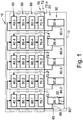
- Figure 1 depicts schematically a pressure sensor calibration system 10 arranged to execute instructions to practice a method of calibrating a pressure sensor 80 in an internal combustion piston engine 12 according to an embodiment of the invention.
- the engine 12 comprises generally several cylinders 30 into each of which a piston 32 is arranged to reciprocate inside the cylinder 30 between the top dead center and the bottom dead center and thus rotate a crank shaft of the engine (not shown).
- FIG. 1 there is illustrated only one cylinder with a piston 30, each of the cylinders 30.1,...,30.n is provided with a piston.
- the cylinder pressure sensor calibration system 10 of the engine 12 comprises a measuring unit 40 arranged to measure pressure in each of the cylinders 30.1,..,30.n during a compression phase before start of the ignition at a crank angle ⁇ 0 using the pressure sensor 80.
- Cylinder pressure of each cylinder 30.1, 30.2, 30.3, 30.4,..., 30.n is measured by the measurement unit 40, individually 40.1, 40.2, 40.3, 40.4,..., 40.n at least at a one predetermined crank angle position ⁇ 0 .
- Each cylinder 30.1, 30.2, 30.3, 30.4,..., 30.n is provided with pressure sensors 80.1, 80.2, 80.3, 80.4,...,80.n to measure the pressure in the cylinder.
- crank angle can be detected by a crank angle determination system 90 and the position is made available to the calibration system 10. Knowing the details of the engine a volume of the combustion chamber in the cylinder can be calculated for any crank angle positions with substantial accuracy.
- the calibration system can be provided with a volume lookup table providing values for cylinder volume for specific, distinct crank angle values.
- the calibration system 10 further comprises a heat release determination unit 50, with optional individual determination units 50.1, 50.2, 50.3, 50.4,..., 50.n for each cylinder, that is arranged to determine a heat release characteristic during a crank angle range ⁇ 0 - ⁇ 1 .
- the heat release characteristic may be a heat release value, which can be determined by any conventional manner, for example, by using a least square estimation.
- equation (4) gives information of possible calibration error in the measurement and a value of equation (4) can be used in closed loop for calibration of the pressure sensors.
- the pressure offset ⁇ p is estimated at an estimation unit 60 comprising estimation units 60.1, 60.2, 60.3, 60.4,..., 60.n for each cylinder 30.1, 30.2, 30.3, 30.4,..., 30.n using the heat release value d ⁇ Q d ⁇ offset determined at the heat release determination unit 50 and the change of cylinder volume .
- a discrete approximation method known as such may be used instead of the integration methods.
- the measurements, determinations and calculations can be made for example at 1 degree of crank angle resolution, or with higher resolution.
- Calibration of the cylinder pressure measurement is obtained at a calibration unit 70 with the estimated pressure offset ⁇ p .
- a line 72 depicts that information concerning the calibration from the calibration unit 70 is taken into account in the measuring unit 40.
- Calibration information via lines 72.1, 72.2, 72.3, 72.4,...,72.n is transferred individually for each cylinders 30.1, 30.2, 30.3, 30.4,..., 30.n.
- the pressure sensors 80 can be calibrated to indicate correct actual pressure prevailing in the cylinder.
- the estimated pressure offset ⁇ p can be used in the measuring unit 40 from the previous cycle. This provides an auto-calibration scheme for the pressure sensors 80 by using cycle to cycle compensation using the offset pressure.
- the pressure is measured more than once at the measuring unit 40, the heat release d ⁇ Q d ⁇ offset is determined at the determination unit 50, the pressure offset ⁇ p is estimated at the estimation unit 60 and the cylinder pressure measurement is calibrated with the estimated offset pressure ⁇ p .
- the pressure in the cylinder is measured three times and three values for pressure is obtained p 1 , p 2 and p 3 .
- thee heat release values which are Q 1 , Q 2 and Q 3 as well as three heat release values d Q 1 d ⁇ , d Q 2 d ⁇ and d Q 3 d ⁇ .
- Three pressure offset values can be determined as ⁇ p 1 , ⁇ p 2 and ⁇ p 3 using the three heat release values Q 1 , Q 2 and Q 3 or preferably three heat release values d Q 1 d ⁇ , d Q 2 d ⁇ and d Q 3 d ⁇ .
- a mean pressure offset ⁇ p ( ⁇ p 1 + ⁇ p 2 + ⁇ p 3 )/3 one gets an estimation for the pressure offset. Then the mean value ⁇ p is used in the calibration and this means that the estimated pressure offset is the mean value ⁇ p of the offset pressures ⁇ p 1 , ⁇ p 2 and ⁇ p 3 .
- Figure 1 illustrates schematically that the measurement unit 40, the determination unit 50, the estimation unit 60 and the calibration unit 70 are individual units. However, it should be understood that the measurement unit 40, the determination unit 50, the estimation unit 60 and the calibration unit 70 may be arranged into a one physical unit that can be called e.g. as an adjustment unit that comprises instructions to measure, determine, estimate and calibrate in a previously described manner.
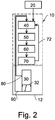
- Figure 2 illustrates another embodiment of the invention.
- the pressure offset ⁇ p is a predetermined value that is taken into account in calibration so as to obtain better pressure information in the cylinder.
- the pressure offset ⁇ p is determined during each compression phase before ignition as described earlier and the determined pressure offset ⁇ p from previous cycle is used in calibration the forward measurement.
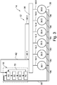
- FIG 3 illustrates schematically the internal combustion piston engine 12 comprising the pressure sensor calibration system 10 arranged calibrate the measured pressure values.
- the engine 12 comprises a receiver 36 from which at least the combustion air is introduced into the cylinders 30.1, 30.2, 30.3, 30.4, 30.5 and 30.6 via conduits 14. Pressure in the receiver 36 is also monitored by a pressure sensor 82.
- the receiver 36 is provided at least one pressure sensor 82 connected into the receiver 36 so as to measure pressure prevailing in the receiver 36.
- Figure 3 shows two pressure sensors 82.1, 82.2 connected to the receiver 36, however, the number of pressure sensors is not restricted to two.
- the pressure sensors 80 in the cylinders 30, the pressure sensors 82 connected into the receiver 36 can be calibrated.
- the pressure information from the receiver 36 is delivered via the measurement unit 40, a heat release in the receiver 36 is obtained at the determination unit 50, and a pressure offset ⁇ p rec in the receiver 36 can be estimated in the estimation unit 60. Finally, calibration of the receiver pressure measurement is obtained at the calibration unit 70 with the estimated pressure offset ⁇ p rec in the receiver 36. Similarly as earlier, the line 72 depicts that information concerning the calibration from the calibration unit 70 is taken into account in the measuring unit 40.
- Figure 3 illustrates schematically six cylinders but in practice the number of cylinders may be different.
Landscapes
- Engineering & Computer Science (AREA)
- Physics & Mathematics (AREA)
- General Physics & Mathematics (AREA)
- Chemical & Material Sciences (AREA)
- Combustion & Propulsion (AREA)
- Mechanical Engineering (AREA)
- General Engineering & Computer Science (AREA)
- Combined Controls Of Internal Combustion Engines (AREA)
- Measuring Fluid Pressure (AREA)
Claims (17)
- Verfahren zur Kalibrierung eines Zylinderdrucksensors (80), der dafür ausgelegt ist, um in einer Brennkraftkolbenmaschine (12) den Druck zu messen, wobei das Verfahren während einer Kompressionsphase vor dem Start der Zündung mindestens die folgenden Schritte umfasst:i. Messen eines Drucks pm , der einen Hinweis auf einen Druck in dem Zylinder (30) bei einem Kurbelwinkelbereich von (ϑ0-ϑ1) liefert,ii. Bestimmen einer Wärmefreisetzungscharakteristik während des Kurbelwinkelbereichs von (ϑ0-ϑ1),iii. Berechnen einer Veränderung eines Zylindervolumens bei dem Kurbelwinkelbereich von (ϑ0-ϑ1),iv. Schätzen einer Druckabweichung Δp des Drucks, der in dem Schritt i. gemessen worden ist, unter Verwendung der Wärmefreisetzungscharakteristik, die in dem Schritt ii. bestimmt worden ist, und der Volumenveränderung, die in dem Schritt iii. bestimmt worden ist.v. Kalibrierung der Zylinderdruckmessung mit der geschätzten Druckabweichung Δp.
- Verfahren zur Kalibrierung eines Zylinderdrucksensors (80) nach Anspruch 1, wobei die Wärmefreisetzungscharakteristik in dem Schritt ii. eine Kurbelwinkelableitung des Wärmefreisetzungswerts ist, und wobei in dem Schritt iv die Druckabweichung als eine Funktion der Ableitung des Wärmefreisetzungswerts und der Volumenveränderung des Zylinders geschätzt wird.
- Verfahren zur Kalibrierung eines Zylinderdrucksensors (80) nach Anspruch 1, wobei die Wärmefreisetzungscharakteristik in dem Schritt ii. ein Wärmefreisetzungswert ist, der aus der Wärmefreisetzungsrate erhalten worden ist.
- Verfahren zur Kalibrierung eines Zylinderdrucksensors (80) nach Anspruch 2, wobei die Druckabweichung Δp unter Verwendung einer Funktion


- Verfahren zur Kalibrierung eines Zylinderdrucksensors (80) nach Anspruch 3, wobei der Schritt des Bestimmens eines Wärmefreisetzungswerts Q während des Kurbelwinkelbereichs von (ϑ0-ϑ1) durchgeführt wird durch

- Verfahren zur Kalibrierung eines Zylinderdrucksensors (80) nach Anspruch 5, dadurch gekennzeichnet, dass die Druckabweichung Δp unter Verwendung einer Funktion

wobei
- Verfahren zur Kalibrierung eines Zylinderdrucksensors (80) nach einem der Ansprüche 1 - 5, wobei der tatsächliche Druck in dem Zylinder (30) erhalten wird, indem die Druckabweichung Δp von dem Druck pm, der einen Hinweis auf den Druck in dem Zylinder (30) liefert, subtrahiert wird.
- Verfahren zur Kalibrierung eines Zylinderdrucksensors (80) nach einem der Ansprüche 1 oder 7, wobei der Druck pm , der einen Hinweis auf den Druck in dem Zylinder (30) liefert, ein Druck ist, der direkt in dem Zylinder (30) gemessen wird.
- Verfahren zur Kalibrierung eines Zylinderdrucksensors (80) nach einem der Ansprüche 1 oder 7, wobei der Druck pm , der einen Hinweis auf den Druck in dem Zylinder (30) liefert, ein Druck ist, der direkt in einem Empfänger der Maschine gemessen wird.
- Verfahren zur Kalibrierung eines Drucksensors (80) nach einem der Ansprüche 1 - 6, wobei die Druckabweichung von Zyklus zu Zyklus von dem vorhergehenden Zyklus verwendet wird, um eine Messeinheit (40) zu kalibrieren, um so die Kalibrierung von Zyklus zu Zyklus zu verbessern.
- Verfahren zur Kalibrierung eines Drucksensors (80) nach Anspruch 1, wobei in einer ersten Kompressionsphase eines ersten Zyklus die Druckabweichung Δp ein vorgegebener Wert ist, der bei der Kalibrierung berücksichtigt werden muss, um eine bessere Druckinformation in dem Zylinder (30) zu erhalten.
- Verfahren zur Kalibrierung eines Drucksensors (80) nach den Ansprüchen 1 - 2, wobei die Schritte i. - iv. während einer Kompressionsphase vor dem Start der Zündung mehr als einmal ausgeführt werden.
- Verfahren zur Kalibrierung eines Drucksensors nach Anspruch 9, wobei die Schritte i. - iii. während einer Kompressionsphase vor dem Start der Zündung mehr als einmal ausgeführt werden, und wobei mehr Druckabweichungen als eine, nämlich Δp1 , ..., Δpk , wobei k > 1 ist, erhalten werden, die als ein Antwortwert in Schritt iv. verwendet werden.
- Verfahren zur Kalibrierung eines Drucksensors (80) nach Anspruch 10, wobei der Schritt iv., ein Mittelwert der Druckabweichung, als ein Antwortwert verwendet wird, der bedeutet, dass die geschätzte Druckabweichung in dem Schritt iv. der Mittelwert
Δp der Druckabweichungen Δp1 , ..., Δpn ist, wobei n > 1 ist. - Brennkraftkolbenmaschine (12), die Folgendes umfasst:a. mindestens einen Zylinder (30),b. einen Kolben (32), der angeordnet ist, um innerhalb des Zylinders (30) eine hin- und hergehende Bewegung durchzuführen,c. mindestens einen Drucksensor (80), der in einer Verbindung mit dem Zylinder (30) angeordnet ist,dadurch gekennzeichnet, dass die Maschine ein Kalibrierungssystem (10) eines Drucksensors umfasst, das eine Messeinheit (40), die angeordnet ist, um einen Druck zu messen, der einen Hinweis auf einen Druck in dem Zylinder mit dem mindestens einen Drucksensor (80) in der Maschine während einer Kompressionsphase vor einem Start einer Zündung in dem Zylinder liefert, eine Einheit (50) zur Bestimmung der Wärmefreisetzung, die angeordnet ist, um eine Wärmefreisetzungscharakteristik zu bestimmen, eine Schätzeinheit (60), die angeordnet ist, um eine Zylinderdruckabweichung der Druckmessung, die unter Verwendung der Wärmefreisetzungscharakteristik und der Veränderung des Zylindervolumens durchgeführt worden ist, zu schätzen, und eine Kalibrierungseinheit (70), die angeordnet ist, um den Drucksensor (80) als Antwort auf die geschätzte Zylinderdruckabweichung zu kalibrieren, umfasst.
- Brennkraftkolbenmaschine nach Anspruch 15, dadurch gekennzeichnet, dass ein Empfänger (36), der mit den Zylindern (30) über Leitungen (14) verbunden ist, mindestens einen Drucksensor (82) umfasst, um einen Druck in dem Empfänger (36) zu messen, und dass er in Verbindung mit dem Kalibrierungssystem (10) steht.
- Brennkraftkolbenmaschine nach Anspruch 15, dadurch gekennzeichnet, dass ein Kalibrierungssystem (10) eines Drucksensors mit Anweisungen versehen ist, um ein Verfahren zur Kalibrierung eines Zylinderdrucksensors nach einem der Ansprüche 1 - 14 auszuführen.
Applications Claiming Priority (1)
| Application Number | Priority Date | Filing Date | Title |
|---|---|---|---|
| PCT/FI2014/051047 WO2016102741A1 (en) | 2014-12-22 | 2014-12-22 | A method of calibrating a pressure sensor and an internal combustion piston engine |
Publications (2)
| Publication Number | Publication Date |
|---|---|
| EP3237871A1 EP3237871A1 (de) | 2017-11-01 |
| EP3237871B1 true EP3237871B1 (de) | 2019-08-07 |
Family
ID=52302252
Family Applications (1)
| Application Number | Title | Priority Date | Filing Date |
|---|---|---|---|
| EP14824864.4A Active EP3237871B1 (de) | 2014-12-22 | 2014-12-22 | Verfahren zur kalibrierung eines drucksensor und einer verbrennungsmaschine |
Country Status (4)
| Country | Link |
|---|---|
| EP (1) | EP3237871B1 (de) |
| KR (1) | KR101855067B1 (de) |
| CN (1) | CN107110733B (de) |
| WO (1) | WO2016102741A1 (de) |
Families Citing this family (2)
| Publication number | Priority date | Publication date | Assignee | Title |
|---|---|---|---|---|
| CN111051670B (zh) * | 2017-08-18 | 2022-03-29 | 瓦锡兰芬兰有限公司 | 控制多气缸内燃发动机中燃料燃烧的方法和配置为控制多气缸内燃活塞发动机中的燃烧过程的计算机控制系统 |
| KR102442206B1 (ko) * | 2017-10-24 | 2022-09-13 | 한국조선해양 주식회사 | 선박용 엔진 및 선박용 엔진 제어방법 |
Citations (1)
| Publication number | Priority date | Publication date | Assignee | Title |
|---|---|---|---|---|
| EP1936157A2 (de) * | 2006-12-20 | 2008-06-25 | Delphi Technologies, Inc. | Verbrennungssteuerung in einem Verbrennungsmotor |
Family Cites Families (10)
| Publication number | Priority date | Publication date | Assignee | Title |
|---|---|---|---|---|
| WO2004022959A1 (ja) | 2002-09-09 | 2004-03-18 | Toyota Jidosha Kabushiki Kaisha | 内燃機関の制御装置 |
| JP4354334B2 (ja) * | 2004-05-20 | 2009-10-28 | 本田技研工業株式会社 | 筒内圧センサの故障を判定する装置 |
| JP2006284533A (ja) * | 2005-04-05 | 2006-10-19 | Honda Motor Co Ltd | 筒内圧力センサの異常検知装置 |
| US7913536B2 (en) * | 2005-07-29 | 2011-03-29 | Sensata Technologies Holland B.V. | Compensation arrangement and method for operation thereof |
| JP2008069714A (ja) * | 2006-09-14 | 2008-03-27 | Toyota Motor Corp | 内燃機関の制御装置 |
| GB2469826B (en) | 2009-04-29 | 2012-11-21 | Gm Global Tech Operations Inc | Method for estimating the pressure prevailing in an intake manifold of an internal combustion engine and method of controlling an internal combustion engine |
| CA2673216C (en) * | 2009-07-31 | 2011-05-03 | Westport Power Inc. | Method and apparatus for reconstructing in-cylinder pressure and correcting for signal decay |
| GB2477122A (en) * | 2010-01-22 | 2011-07-27 | Gm Global Tech Operations Inc | Determining the pressure offset of an in-cylinder pressure sensor of an i.c. engine |
| DE102012203097B3 (de) * | 2012-02-29 | 2013-04-11 | Continental Automotive Gmbh | Verfahren und Vorrichtung zum Bestimmen eines Fehlers einer Druckmessung in einem Druckbehälter |
| US9316558B2 (en) * | 2013-06-04 | 2016-04-19 | GM Global Technology Operations LLC | System and method to diagnose fuel system pressure sensor |
-
2014
- 2014-12-22 EP EP14824864.4A patent/EP3237871B1/de active Active
- 2014-12-22 KR KR1020177014673A patent/KR101855067B1/ko active Active
- 2014-12-22 WO PCT/FI2014/051047 patent/WO2016102741A1/en not_active Ceased
- 2014-12-22 CN CN201480084085.4A patent/CN107110733B/zh active Active
Patent Citations (1)
| Publication number | Priority date | Publication date | Assignee | Title |
|---|---|---|---|---|
| EP1936157A2 (de) * | 2006-12-20 | 2008-06-25 | Delphi Technologies, Inc. | Verbrennungssteuerung in einem Verbrennungsmotor |
Also Published As
| Publication number | Publication date |
|---|---|
| EP3237871A1 (de) | 2017-11-01 |
| KR101855067B1 (ko) | 2018-06-25 |
| CN107110733A (zh) | 2017-08-29 |
| WO2016102741A1 (en) | 2016-06-30 |
| KR20170065670A (ko) | 2017-06-13 |
| CN107110733B (zh) | 2019-06-04 |
Similar Documents
| Publication | Publication Date | Title |
|---|---|---|
| EP1936157B1 (de) | Verbrennungssteuerung in einem Verbrennungsmotor | |
| US8862366B2 (en) | Controller for and method of controlling internal combustion engine | |
| CN105927408B (zh) | 用于内燃机的控制装置和控制方法 | |
| EP2481907B1 (de) | Steuerungsvorrichtung für einen verbrennungsmotor | |
| EP3237871B1 (de) | Verfahren zur kalibrierung eines drucksensor und einer verbrennungsmaschine | |
| JPH03130560A (ja) | クランクケース掃気式2ストロークエンジンへの空気量を判定する装置及び方法 | |
| Pipitone et al. | The experimental validation of a new thermodynamic method for TDC determination | |
| CN104179573A (zh) | 一种内燃机分缸燃烧状态估计方法 | |
| US7295917B2 (en) | Method for determining a combustion chamber pressure | |
| CN108495990A (zh) | 根据温度对发动机进气管线中压力传感器进行校准的方法 | |
| EP4062141B1 (de) | Verfahren zur erkennung einer abweichung beim betrieb eines drucksensors für einen innenverbrennungskolbenmotor und einen lesbaren speichergerät zum erkennen einer abweichung im betrieb eines drucksensors | |
| EP3669060B1 (de) | Verfahren zur steuerung der verbrennung von kraftstoff in einem mehrzylinder-verbrennungsmotor und rechnersteuerungssystem zur steuerung des verbrennungsprozesses in einem mehrzylinder-kolbenverbrennungsmotor | |
| CN110608105B (zh) | 一种充气效率的自动标定方法和装置 | |
| EP3320200B1 (de) | Verfahren und steuerungssystem zur bestimmung eines versatzes in bezug auf eine kurbelwinkelmessung | |
| JPS63134845A (ja) | 排気ガス再循環制御装置 | |
| JP7593869B2 (ja) | 内燃機関制御装置 | |
| JP4684944B2 (ja) | 内燃機関の制御装置 | |
| JP2008274796A (ja) | 可変圧縮比エンジンのトルク推定装置 | |
| CN119122679A (zh) | 一种凸轮轴相位修正方法、装置及车辆 | |
| KR101490933B1 (ko) | 연소압 센서를 이용한 부스트 압력 측정 방법 | |
| JP2007315340A (ja) | 内燃機関の特性パラメータ計測方法 | |
| JP2007023974A (ja) | 内燃機関の図示平均有効圧の推定方法 | |
| Pipitone et al. | SAE TECHNICAL | |
| JP2015206306A (ja) | 内燃機関の吸気量バラツキ検出装置 | |
| JPH087084B2 (ja) | 内燃機関の吸入空気量検出装置 |
Legal Events
| Date | Code | Title | Description |
|---|---|---|---|
| STAA | Information on the status of an ep patent application or granted ep patent |
Free format text: STATUS: THE INTERNATIONAL PUBLICATION HAS BEEN MADE |
|
| PUAI | Public reference made under article 153(3) epc to a published international application that has entered the european phase |
Free format text: ORIGINAL CODE: 0009012 |
|
| STAA | Information on the status of an ep patent application or granted ep patent |
Free format text: STATUS: REQUEST FOR EXAMINATION WAS MADE |
|
| 17P | Request for examination filed |
Effective date: 20170705 |
|
| AK | Designated contracting states |
Kind code of ref document: A1 Designated state(s): AL AT BE BG CH CY CZ DE DK EE ES FI FR GB GR HR HU IE IS IT LI LT LU LV MC MK MT NL NO PL PT RO RS SE SI SK SM TR |
|
| AX | Request for extension of the european patent |
Extension state: BA ME |
|
| DAX | Request for extension of the european patent (deleted) | ||
| GRAP | Despatch of communication of intention to grant a patent |
Free format text: ORIGINAL CODE: EPIDOSNIGR1 |
|
| STAA | Information on the status of an ep patent application or granted ep patent |
Free format text: STATUS: GRANT OF PATENT IS INTENDED |
|
| INTG | Intention to grant announced |
Effective date: 20190326 |
|
| GRAS | Grant fee paid |
Free format text: ORIGINAL CODE: EPIDOSNIGR3 |
|
| GRAA | (expected) grant |
Free format text: ORIGINAL CODE: 0009210 |
|
| STAA | Information on the status of an ep patent application or granted ep patent |
Free format text: STATUS: THE PATENT HAS BEEN GRANTED |
|
| AK | Designated contracting states |
Kind code of ref document: B1 Designated state(s): AL AT BE BG CH CY CZ DE DK EE ES FI FR GB GR HR HU IE IS IT LI LT LU LV MC MK MT NL NO PL PT RO RS SE SI SK SM TR |
|
| REG | Reference to a national code |
Ref country code: GB Ref legal event code: FG4D |
|
| REG | Reference to a national code |
Ref country code: CH Ref legal event code: EP Ref country code: AT Ref legal event code: REF Ref document number: 1164603 Country of ref document: AT Kind code of ref document: T Effective date: 20190815 |
|
| REG | Reference to a national code |
Ref country code: DE Ref legal event code: R096 Ref document number: 602014051468 Country of ref document: DE |
|
| REG | Reference to a national code |
Ref country code: IE Ref legal event code: FG4D |
|
| RAP2 | Party data changed (patent owner data changed or rights of a patent transferred) |
Owner name: WAERTSILAE FINLAND OY |
|
| REG | Reference to a national code |
Ref country code: NL Ref legal event code: MP Effective date: 20190807 |
|
| REG | Reference to a national code |
Ref country code: LT Ref legal event code: MG4D |
|
| PG25 | Lapsed in a contracting state [announced via postgrant information from national office to epo] |
Ref country code: HR Free format text: LAPSE BECAUSE OF FAILURE TO SUBMIT A TRANSLATION OF THE DESCRIPTION OR TO PAY THE FEE WITHIN THE PRESCRIBED TIME-LIMIT Effective date: 20190807 Ref country code: LT Free format text: LAPSE BECAUSE OF FAILURE TO SUBMIT A TRANSLATION OF THE DESCRIPTION OR TO PAY THE FEE WITHIN THE PRESCRIBED TIME-LIMIT Effective date: 20190807 Ref country code: NO Free format text: LAPSE BECAUSE OF FAILURE TO SUBMIT A TRANSLATION OF THE DESCRIPTION OR TO PAY THE FEE WITHIN THE PRESCRIBED TIME-LIMIT Effective date: 20191107 Ref country code: NL Free format text: LAPSE BECAUSE OF FAILURE TO SUBMIT A TRANSLATION OF THE DESCRIPTION OR TO PAY THE FEE WITHIN THE PRESCRIBED TIME-LIMIT Effective date: 20190807 Ref country code: BG Free format text: LAPSE BECAUSE OF FAILURE TO SUBMIT A TRANSLATION OF THE DESCRIPTION OR TO PAY THE FEE WITHIN THE PRESCRIBED TIME-LIMIT Effective date: 20191107 Ref country code: PT Free format text: LAPSE BECAUSE OF FAILURE TO SUBMIT A TRANSLATION OF THE DESCRIPTION OR TO PAY THE FEE WITHIN THE PRESCRIBED TIME-LIMIT Effective date: 20191209 Ref country code: FI Free format text: LAPSE BECAUSE OF FAILURE TO SUBMIT A TRANSLATION OF THE DESCRIPTION OR TO PAY THE FEE WITHIN THE PRESCRIBED TIME-LIMIT Effective date: 20190807 Ref country code: SE Free format text: LAPSE BECAUSE OF FAILURE TO SUBMIT A TRANSLATION OF THE DESCRIPTION OR TO PAY THE FEE WITHIN THE PRESCRIBED TIME-LIMIT Effective date: 20190807 |
|
| PG25 | Lapsed in a contracting state [announced via postgrant information from national office to epo] |
Ref country code: RS Free format text: LAPSE BECAUSE OF FAILURE TO SUBMIT A TRANSLATION OF THE DESCRIPTION OR TO PAY THE FEE WITHIN THE PRESCRIBED TIME-LIMIT Effective date: 20190807 Ref country code: IS Free format text: LAPSE BECAUSE OF FAILURE TO SUBMIT A TRANSLATION OF THE DESCRIPTION OR TO PAY THE FEE WITHIN THE PRESCRIBED TIME-LIMIT Effective date: 20191207 Ref country code: LV Free format text: LAPSE BECAUSE OF FAILURE TO SUBMIT A TRANSLATION OF THE DESCRIPTION OR TO PAY THE FEE WITHIN THE PRESCRIBED TIME-LIMIT Effective date: 20190807 Ref country code: GR Free format text: LAPSE BECAUSE OF FAILURE TO SUBMIT A TRANSLATION OF THE DESCRIPTION OR TO PAY THE FEE WITHIN THE PRESCRIBED TIME-LIMIT Effective date: 20191108 Ref country code: AL Free format text: LAPSE BECAUSE OF FAILURE TO SUBMIT A TRANSLATION OF THE DESCRIPTION OR TO PAY THE FEE WITHIN THE PRESCRIBED TIME-LIMIT Effective date: 20190807 |
|
| PG25 | Lapsed in a contracting state [announced via postgrant information from national office to epo] |
Ref country code: TR Free format text: LAPSE BECAUSE OF FAILURE TO SUBMIT A TRANSLATION OF THE DESCRIPTION OR TO PAY THE FEE WITHIN THE PRESCRIBED TIME-LIMIT Effective date: 20190807 |
|
| PG25 | Lapsed in a contracting state [announced via postgrant information from national office to epo] |
Ref country code: EE Free format text: LAPSE BECAUSE OF FAILURE TO SUBMIT A TRANSLATION OF THE DESCRIPTION OR TO PAY THE FEE WITHIN THE PRESCRIBED TIME-LIMIT Effective date: 20190807 Ref country code: DK Free format text: LAPSE BECAUSE OF FAILURE TO SUBMIT A TRANSLATION OF THE DESCRIPTION OR TO PAY THE FEE WITHIN THE PRESCRIBED TIME-LIMIT Effective date: 20190807 Ref country code: RO Free format text: LAPSE BECAUSE OF FAILURE TO SUBMIT A TRANSLATION OF THE DESCRIPTION OR TO PAY THE FEE WITHIN THE PRESCRIBED TIME-LIMIT Effective date: 20190807 Ref country code: PL Free format text: LAPSE BECAUSE OF FAILURE TO SUBMIT A TRANSLATION OF THE DESCRIPTION OR TO PAY THE FEE WITHIN THE PRESCRIBED TIME-LIMIT Effective date: 20190807 |
|
| PG25 | Lapsed in a contracting state [announced via postgrant information from national office to epo] |
Ref country code: SK Free format text: LAPSE BECAUSE OF FAILURE TO SUBMIT A TRANSLATION OF THE DESCRIPTION OR TO PAY THE FEE WITHIN THE PRESCRIBED TIME-LIMIT Effective date: 20190807 Ref country code: CZ Free format text: LAPSE BECAUSE OF FAILURE TO SUBMIT A TRANSLATION OF THE DESCRIPTION OR TO PAY THE FEE WITHIN THE PRESCRIBED TIME-LIMIT Effective date: 20190807 Ref country code: SM Free format text: LAPSE BECAUSE OF FAILURE TO SUBMIT A TRANSLATION OF THE DESCRIPTION OR TO PAY THE FEE WITHIN THE PRESCRIBED TIME-LIMIT Effective date: 20190807 Ref country code: IS Free format text: LAPSE BECAUSE OF FAILURE TO SUBMIT A TRANSLATION OF THE DESCRIPTION OR TO PAY THE FEE WITHIN THE PRESCRIBED TIME-LIMIT Effective date: 20200224 |
|
| REG | Reference to a national code |
Ref country code: DE Ref legal event code: R097 Ref document number: 602014051468 Country of ref document: DE |
|
| PLBE | No opposition filed within time limit |
Free format text: ORIGINAL CODE: 0009261 |
|
| STAA | Information on the status of an ep patent application or granted ep patent |
Free format text: STATUS: NO OPPOSITION FILED WITHIN TIME LIMIT |
|
| PG2D | Information on lapse in contracting state deleted |
Ref country code: IS |
|
| REG | Reference to a national code |
Ref country code: CH Ref legal event code: PL |
|
| 26N | No opposition filed |
Effective date: 20200603 |
|
| REG | Reference to a national code |
Ref country code: BE Ref legal event code: MM Effective date: 20191231 |
|
| PG25 | Lapsed in a contracting state [announced via postgrant information from national office to epo] |
Ref country code: SI Free format text: LAPSE BECAUSE OF FAILURE TO SUBMIT A TRANSLATION OF THE DESCRIPTION OR TO PAY THE FEE WITHIN THE PRESCRIBED TIME-LIMIT Effective date: 20190807 Ref country code: MC Free format text: LAPSE BECAUSE OF FAILURE TO SUBMIT A TRANSLATION OF THE DESCRIPTION OR TO PAY THE FEE WITHIN THE PRESCRIBED TIME-LIMIT Effective date: 20190807 |
|
| GBPC | Gb: european patent ceased through non-payment of renewal fee |
Effective date: 20191222 |
|
| PG25 | Lapsed in a contracting state [announced via postgrant information from national office to epo] |
Ref country code: LU Free format text: LAPSE BECAUSE OF NON-PAYMENT OF DUE FEES Effective date: 20191222 Ref country code: IE Free format text: LAPSE BECAUSE OF NON-PAYMENT OF DUE FEES Effective date: 20191222 Ref country code: ES Free format text: LAPSE BECAUSE OF FAILURE TO SUBMIT A TRANSLATION OF THE DESCRIPTION OR TO PAY THE FEE WITHIN THE PRESCRIBED TIME-LIMIT Effective date: 20190807 Ref country code: FR Free format text: LAPSE BECAUSE OF NON-PAYMENT OF DUE FEES Effective date: 20191231 Ref country code: GB Free format text: LAPSE BECAUSE OF NON-PAYMENT OF DUE FEES Effective date: 20191222 |
|
| PG25 | Lapsed in a contracting state [announced via postgrant information from national office to epo] |
Ref country code: BE Free format text: LAPSE BECAUSE OF NON-PAYMENT OF DUE FEES Effective date: 20191231 Ref country code: CH Free format text: LAPSE BECAUSE OF NON-PAYMENT OF DUE FEES Effective date: 20191231 Ref country code: LI Free format text: LAPSE BECAUSE OF NON-PAYMENT OF DUE FEES Effective date: 20191231 |
|
| PG25 | Lapsed in a contracting state [announced via postgrant information from national office to epo] |
Ref country code: CY Free format text: LAPSE BECAUSE OF FAILURE TO SUBMIT A TRANSLATION OF THE DESCRIPTION OR TO PAY THE FEE WITHIN THE PRESCRIBED TIME-LIMIT Effective date: 20190807 |
|
| PG25 | Lapsed in a contracting state [announced via postgrant information from national office to epo] |
Ref country code: MT Free format text: LAPSE BECAUSE OF FAILURE TO SUBMIT A TRANSLATION OF THE DESCRIPTION OR TO PAY THE FEE WITHIN THE PRESCRIBED TIME-LIMIT Effective date: 20190807 Ref country code: HU Free format text: LAPSE BECAUSE OF FAILURE TO SUBMIT A TRANSLATION OF THE DESCRIPTION OR TO PAY THE FEE WITHIN THE PRESCRIBED TIME-LIMIT; INVALID AB INITIO Effective date: 20141222 |
|
| PG25 | Lapsed in a contracting state [announced via postgrant information from national office to epo] |
Ref country code: MK Free format text: LAPSE BECAUSE OF FAILURE TO SUBMIT A TRANSLATION OF THE DESCRIPTION OR TO PAY THE FEE WITHIN THE PRESCRIBED TIME-LIMIT Effective date: 20190807 |
|
| REG | Reference to a national code |
Ref country code: AT Ref legal event code: UEP Ref document number: 1164603 Country of ref document: AT Kind code of ref document: T Effective date: 20190807 |
|
| PGFP | Annual fee paid to national office [announced via postgrant information from national office to epo] |
Ref country code: DE Payment date: 20251211 Year of fee payment: 12 |
|
| PGFP | Annual fee paid to national office [announced via postgrant information from national office to epo] |
Ref country code: AT Payment date: 20251222 Year of fee payment: 12 |
|
| PGFP | Annual fee paid to national office [announced via postgrant information from national office to epo] |
Ref country code: IT Payment date: 20251223 Year of fee payment: 12 |