EP3236552B1 - Triple redundant digital protective relay and operating method therefor - Google Patents
Triple redundant digital protective relay and operating method therefor Download PDFInfo
- Publication number
- EP3236552B1 EP3236552B1 EP15870250.6A EP15870250A EP3236552B1 EP 3236552 B1 EP3236552 B1 EP 3236552B1 EP 15870250 A EP15870250 A EP 15870250A EP 3236552 B1 EP3236552 B1 EP 3236552B1
- Authority
- EP
- European Patent Office
- Prior art keywords
- monitoring control
- power monitoring
- circuit breaker
- voting
- control device
- Prior art date
- Legal status (The legal status is an assumption and is not a legal conclusion. Google has not performed a legal analysis and makes no representation as to the accuracy of the status listed.)
- Active
Links
Images


Classifications
-
- H—ELECTRICITY
- H02—GENERATION; CONVERSION OR DISTRIBUTION OF ELECTRIC POWER
- H02H—EMERGENCY PROTECTIVE CIRCUIT ARRANGEMENTS
- H02H3/00—Emergency protective circuit arrangements for automatic disconnection directly responsive to an undesired change from normal electric working condition with or without subsequent reconnection ; integrated protection
- H02H3/02—Details
- H02H3/05—Details with means for increasing reliability, e.g. redundancy arrangements
-
- H—ELECTRICITY
- H02—GENERATION; CONVERSION OR DISTRIBUTION OF ELECTRIC POWER
- H02B—BOARDS, SUBSTATIONS OR SWITCHING ARRANGEMENTS FOR THE SUPPLY OR DISTRIBUTION OF ELECTRIC POWER
- H02B1/00—Frameworks, boards, panels, desks, casings; Details of substations or switching arrangements
- H02B1/20—Bus-bar or other wiring layouts, e.g. in cubicles, in switchyards
-
- H—ELECTRICITY
- H02—GENERATION; CONVERSION OR DISTRIBUTION OF ELECTRIC POWER
- H02H—EMERGENCY PROTECTIVE CIRCUIT ARRANGEMENTS
- H02H3/00—Emergency protective circuit arrangements for automatic disconnection directly responsive to an undesired change from normal electric working condition with or without subsequent reconnection ; integrated protection
- H02H3/08—Emergency protective circuit arrangements for automatic disconnection directly responsive to an undesired change from normal electric working condition with or without subsequent reconnection ; integrated protection responsive to excess current
- H02H3/083—Emergency protective circuit arrangements for automatic disconnection directly responsive to an undesired change from normal electric working condition with or without subsequent reconnection ; integrated protection responsive to excess current for three-phase systems
-
- H—ELECTRICITY
- H02—GENERATION; CONVERSION OR DISTRIBUTION OF ELECTRIC POWER
- H02H—EMERGENCY PROTECTIVE CIRCUIT ARRANGEMENTS
- H02H3/00—Emergency protective circuit arrangements for automatic disconnection directly responsive to an undesired change from normal electric working condition with or without subsequent reconnection ; integrated protection
- H02H3/42—Emergency protective circuit arrangements for automatic disconnection directly responsive to an undesired change from normal electric working condition with or without subsequent reconnection ; integrated protection responsive to product of voltage and current
- H02H3/427—Emergency protective circuit arrangements for automatic disconnection directly responsive to an undesired change from normal electric working condition with or without subsequent reconnection ; integrated protection responsive to product of voltage and current using induction relays
-
- H—ELECTRICITY
- H02—GENERATION; CONVERSION OR DISTRIBUTION OF ELECTRIC POWER
- H02H—EMERGENCY PROTECTIVE CIRCUIT ARRANGEMENTS
- H02H1/00—Details of emergency protective circuit arrangements
- H02H1/0061—Details of emergency protective circuit arrangements concerning transmission of signals
-
- H—ELECTRICITY
- H02—GENERATION; CONVERSION OR DISTRIBUTION OF ELECTRIC POWER
- H02H—EMERGENCY PROTECTIVE CIRCUIT ARRANGEMENTS
- H02H7/00—Emergency protective circuit arrangements specially adapted for specific types of electric machines or apparatus or for sectionalised protection of cable or line systems, and effecting automatic switching in the event of an undesired change from normal working conditions
- H02H7/26—Sectionalised protection of cable or line systems, e.g. for disconnecting a section on which a short-circuit, earth fault, or arc discharge has occured
- H02H7/261—Sectionalised protection of cable or line systems, e.g. for disconnecting a section on which a short-circuit, earth fault, or arc discharge has occured involving signal transmission between at least two stations
Definitions
- the present invention relates to a digital protective relay, and more particularly, a triple redundant digital protective relay and an operating method therefor.
- protective relays are core devices for a health of a power system and are configured to analyze/monitor an operating state of a power system in real time and break a fault current flowing through a failed system by outputting a circuit breaker open signal immediately when a failure is detected, so as to prevent an electrical or mechanical failure of the power system from spreading to economical loss or unfortunate accident such as loss of precious human lives.
- the most basic duty of such protective relays may be defined by operation sensitivity, selectivity, and speed.
- the operation sensitivity is an ability to recognize even a minimum failure
- the selectivity is an ability to not misjudge a non-failure phenomenon as a failure
- the speed is an ability to operate as fast as possible so as to minimize a damage caused by a failure or spreading of the damage. Any one of them cannot be neglected.
- the protective relay fails to properly perform its operational duty, it may affect not only disruption of production or stoppage of work but also social disturbance, security, and the like.
- blackouts occurred due to a series of malfunctions of relays in several countries including Korea. Since such blackouts are global issues and spread to economic and social problems, it is urgent that countermeasures be established.
- test level defined in the specification is oriented toward generalization due to the attribute of the standard, it is hard to go beyond the basics. This can be seen from the fact that all the protective relays that have caused the large and small accidents of power systems until now were products certified as international standard.
- a hybrid multiple redundant computer system is known from US 6 550 018 B1 .
- This computer system is having at least three parallel operating processing units.
- Each processing unit includes a watch dog controller that monitors the associated central processor module and transfers an alarm signal to each output module in the event that a central processor module fails.
- EP 0 275 362 A2 discloses a safety control safeguard system that includes several sensors disposed in a quadruple array.
- First, second, third and fourth signal processing channels provided in parallel each include signal processing means for receiving output signals from the preferablyated sensors for producing a trip signal.
- First and second actuating means operable independent of each other are provided for actuating an apparatus to be controlled.
- a first switch means operatively connected to the first, second, third and fourth processing channel for activating the first actuating means in response to reception of the trip signal produced by the signal processing channels and second switch means operatively connected to the first, second, third and fourth processing channels for activating the second actuating means in response to reception of the trip signal produced by the signal processing channels.
- the first and second switching means are operable independent of each other and constitute a 2-out-of-4 logic circuit in cooperation with the first and second actuating means.
- a fale-safe and fall-tolerant alternating current output circuit is disclosed by US 4 926 281 A .
- This circuit is coupled to a programmable controller for controlling a load supply through alternating-current power lines, including a fuse and a single controlled output switch connected in series with the load and a pair of series-connected crowbar switches connected together across the ac power lines.
- the crowbar switches can be commanded closed separately to check their operation without blowing the fuse.
- the present invention has been made in an effort to solve the problems of the prior art.
- the invention is defined in the independent apparatus claim 1 and in the independent method claim 5.
- the preferred embodiments are defined in the dependent claims 2-4 and 6. It is an object of the present invention to provide a triple redundant digital protective relay, which implements a core function module of the protective relay in triple redundant structures and controls a circuit breaker for separating a failed power system based on a 2 out of 3 voting using real-time data communication between the implemented triple redundant modules, and an operating method therefor.
- a triple redundant digital protective relay includes: three power monitoring control devices which have a triple redundant structure and control a circuit breaker for separating a failed power system based on a 2 out of 3 voting using real-time mutual data communication; and a central communication device which acquires data related to an operating state of the power system from the three power monitoring control devices and manages the acquired data related to the operating state of the power system.
- the power monitoring control device further includes: a CPU which controls a circuit breaker for separating a failed power system based on a 2 out of 3 voting using real-time data communication with other power monitoring control devices; a first circuit breaker trip circuit which is implemented by one signal relay as an output contact point for a trip control of the circuit breaker according to a control signal from the CPU; and a second circuit breaker trip circuit which is implemented by two signal relays connected in series as an output contact point for a trip control of the circuit breaker according to a control signal from the CPU.
- the power monitoring control device may control the one signal relay of the first circuit breaker trip circuit according to a logic operation result thereof based on a 1 out of 2 voting or a 2 out of 2 voting.
- the power monitoring control device may control the circuit breaker by using a logic operation based on the 1 out of 2 voting or the 2 out of 2 voting.
- the power monitoring control device may control one of the two signal relays connected in series according to a logic operation result thereof based on a 2 out of 3 voting, and control the other signal relay according to a logic operation result based on a 2 out of 3 voting of another power monitoring control device.
- the power monitoring control device may control the circuit breaker by using a logic operation based on the 2 out of 3 voting.
- the power monitoring control device detects a failure or non-failure of the power system based on quantity of electricity calculated based on a voltage and a current, and transmits a detection result to other power monitoring control devices by using a voting bus, so as to share the detection result with the other power monitoring control devices.
- a method for operating a triple redundant digital protective relay includes: detecting a failure or non-failure of a power system based on quantity of electricity calculated based on a voltage and a current; controlling a circuit breaker for separating a failed power system based on a 2 out of 3 voting using real-time mutual data communication through three power monitoring control devices which have a triple redundant structure; and acquiring data related to an operating state of the power system from the three power monitoring control devices and managing the acquired data related to the operating state of the power system.
- the controlling may include controlling the circuit breaker by using a logic operation based on the 1 out of 2 voting or the 2 out of 2 voting.
- the controlling includes controlling the circuit breaker by using a logic operation based on the 2 out of 3 voting.
- the present invention has an effect that can efficiently prevent malfunction or incorrect operation of a protective relay by implementing a core function module of the protective relay in triple redundant structures and controlling a circuit breaker for separating a failed power system based on a 2 out of 3 voting using real-time data communication between the implemented triple redundant modules.
- the present invention has an effect that can stably operate a system because malfunction or incorrect operation can be prevented based on a logic operation using a 2 out of 3 voting.
- the present invention has an effect that can improve reliability because a system can be stably operated based on a logic operation using a 2 out of 3 voting.
- the present invention proposes a novel method which implements a core function module of the protective relay in triple redundant structures and controls a circuit breaker for separating a failed power system based on a 2 out of 3 voting using real-time data communication between the implemented triple redundant modules.
- the present invention has the following technical problems for high reliability, high performance, multifunction, low cost, improvement of network efficiency, and improvement of engineering and ease of use, as compared with an existing triple redundant protection system.
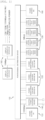
- FIG. 1 is a diagram illustrating an internal configuration of a triple redundant digital protective relay according to an embodiment of the present invention.
- the triple redundant digital protective relay may include power sources 110, power monitoring control devices 120, input/output contact point processing devices 130, a central communication device 140, a power/signal distribution device 150, and display operation devices 160.
- the power source 110 may convert AC 110 V or DC 125 V into low-voltage power suitable for internal circuit operations of the protective relay and supply electrical energy alone or in parallel.
- the power monitoring control device 120 may detect a voltage and a current of a power system, perform digital signal processing through analog-to-digital conversion, calculate various electricity quantities through a metering operation, monitor a failure of the power system through electricity quantity analysis, asymmetrically exchange information when a failure or abnormality occurs, derive a high-reliability determination result through a 2 out of 3 voting logic, and control a circuit breaker or other power devices.
- the power monitoring control device 120 may have a triple redundant structure. Specifically, the power monitoring control device may operate in a single mode which drives one module when an internal failure is defected from two modules, that is, power monitoring control devices, may operate in a dual redundant mode of a 2 out of 2 voting or a 1 out of 2 voting which drives two modules when an internal failure is detected from one module, and may operate in a triple redundant mode of a 2 out of 3 voting which drives three modules when no internal failure is detected.
- the input/output contact point processing device 130 may monitor an operating state of the power system at a digital input contact point, generate a control signal and an alarm signal of the protective relay at a digital output contact point to the outside, select up to four devices so as to be suitable for field application, and mount the selected devices on the protective relay.
- the central communication device 140 may acquire operating state data of the power system, various electricity quantity metering values, and events from the power monitoring control device 120 and the input/output contact point processing device 130, may record and manage the acquired information in a database, may transmit the information of the database via communication in response to a request from an external device outside the protective relay, or may receive a command from an external device via communication, transmit data to an internal device inside the protective device, and process the data.
- the power/signal distribution device 150 may be connected to the respective devices inside the protective relay, supply power to the respective devices, and perform communication and signal exchange between the respective devices.
- the display operation device 160 may communicate with the central communication device to acquire and display the operating state of the protective relay recorded in the database and the operating state of the power system detected by the protective relay.
- the display operation device 160 may include a button that allows a field user to issue a command to change operation characteristics of the protective relay or allows a field user to perform an operation for controlling the protective relay.
- FIG. 2 is a diagram illustrating an internal network configuration of the triple redundant digital protective relay.
- the central communication device may transmit and receive a variety of information while interworking with the power monitoring control devices by using Ethernet communication, and transmit and receive a variety of information while interworking between the power monitoring control devices or the input/output contact point processing devices by using CAN communication.
- Ethernet communication and the CAN communication have been described as an example, but the present invention is not necessarily limited thereto. If necessary, various communication schemes may be applied.
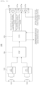
- FIG. 3 is a diagram illustrating a functional structure of the power monitoring control device illustrated in FIG. 1 .
- the power monitoring control device 120 may include a current transformer 121, a potential transformer 122, an A/D signal converter 123, a digital signal processor (DSP) 124, a central processing unit (CPU) 125, a first circuit breaker trip circuit 126, and a second circuit breaker trip circuit 127.
- DSP digital signal processor
- CPU central processing unit
- the current transformer 121 is also referred to as CT and may transform a current flowing through a power line into a current having a small magnitude which can be processed by the power monitoring control device.
- the potential transformer 122 is also referred to as PT and may transform a voltage of the power system into a low level voltage which can be detected by the power monitoring control device.
- the A/D signal converter 123 may receive a converted analog signal from the current transformer 121 and the potential transformer 122 and convert the received analog signal into a digital signal.
- the DSP 124 may perform signal processing on voltage and current signals of the power system, which are converted through the A/D signal converter, and perform various electricity quantity metering and measurement functions based on the signal processing result.
- the CPU 125 may monitor a health of the power system by using voltage, current, and various electricity quantity data received from the DSP 124, and detect failure or non-failure of the power system through various failure detection algorithms.
- the CPU 125 shares the result of monitoring the power system with other power monitoring control devices in real time.
- the CPU 125 When the failure of the power system is determined, the CPU 125 immediately transfers the determination result to the first circuit breaker trip circuit 126 and the second circuit breaker trip circuit 127 and performs a control function for promptly separating the failed system from the healthy system. In order for high-reliability failure monitoring and control, the CPU 125 shares the operation result information with other power monitoring control devices via dedicated communication by transmitting or receiving the operation result information. In a condition that all the three power monitoring control devices perform the normal operations without abnormality, the CPU 125 determines the operation result information of the other two power monitoring control devices other than the operation result information of one power monitoring control device through a 2 out of 3 voting mechanism, and controls a circuit breaker trip contact point 127a at which two control contact point devices are configured in series. A circuit breaker trip contact point 127b is controlled by a signal generated through a 2 out of 3 mechanism by another power monitoring control device.
- the first circuit breaker trip circuit 126 and the second circuit breaker trip circuit 127 may control the circuit breakers according to the control based on the operation result information of the power monitoring control device of the CPU 125.
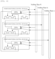
- FIG. 4 is a diagram illustrating a mutual connection relationship of the power monitoring control devices having a triple redundant structure.
- the power monitoring control devices having the triple redundant structure according to the present invention may share operation result information with one another by using voting buses by transmitting and receiving the operation result information.
- the power monitoring control device #1 transmits its own operation result information via a voting bus A, receives operation result information of the power monitoring control device #2 via a voting bus B, and receive operation result information of the power monitoring control device #3 via a voting bus C.
- the power monitoring control device #2 transmits its own operation result information via the voting bus B, receives operation result information of the power monitoring control device #1 via the voting bus A, and receive operation result information of the power monitoring control device #3 via the voting bus C.
- the power monitoring control device #3 transmits its own operation result information via the voting bus C, receives operation result information of the power monitoring control device #1 via the voting bus A, and receive operation result information of the power monitoring control device #2 via the voting bus B.
- FIG. 5 is a diagram illustrating the operation mechanism of the power monitoring control devices illustrated in FIG. 1 .
- the key operation of the triple redundant protective relay includes a protective relay algorithm operation that allows each of the power monitoring control devices to receive the voltage and current of the power system through the potential transformer and the current transformer, meters the quantity of electricity, monitors the operating state of the power system, and monitors and detects the failure of the power system, and any operations in which the state monitoring of the circuit breaker is performed, the result is exchanged via dedicated communication between the power monitoring control devices, each of the three power monitoring control devices compares its own determination result with the determination results of the other two power monitoring control devices through a 2 out of 3 voting logic, the determination results are evaluated as reliable when two or more determination results are identical to each other, the determination results are input to a user-defined logic function, and the power device is controlled by outputting control and alarm signals calculated as a user-defined logic operation result to the outside.
- a protective relay algorithm operation that allows each of the power monitoring control devices to receive the voltage and current of the power system through the potential transformer and the current transformer, meters the quantity of electricity, monitors the operating state of the power system, and monitor
- Each of the power monitoring control devices includes two output contact points for trip control of the power device, in particular, the circuit breaker.
- one contact point constitutes two signal relays in series.
- One of the two signal relays connected in series is controlled based on the power monitoring control device's own 2 out of 3 voting logic operation result, and the other signal relay is controlled based on a 2 out of voting logic operation result of another power monitoring control device.
- the external output is allowed only when the two signal relays operate. Risk factors that may cause the triple redundant protective relay to malfunction due to the failure of the single signal relay itself or the control circuit thereof are excluded.
- a signal for controlling a signal relay of another power monitoring control device is transmitted to an inner layer conductor of a printed circuit board (PCB) through a differential transmission device, the structure is robust against external noise or command mode noise that resonates with a switching frequency of a peripheral circuit.
- the signal for controlling the signal relay of another power monitoring control device is output in a valid state only when the 2 out of 3 voting trip operation result of the power monitoring control device that is a signal transmitter is true, this is also a structure that excludes a malfunction.
- a signal relay capable of being autonomously controlled may be incorrectly operated, and both the two signal relays may malfunction only when the failure or error occurs in another power monitoring control device that is another signal relay controller connected in series.
- This is for a security failure of a serial dual redundant mode and is a mode having a lowest security failure as compared with a single mode, a parallel dual redundant mode, and a serial/parallel triple redundant mode. It can be said that the possibility thereof is also low.
- Each of the power monitoring control devices generates two or more same determination results logically by a 2 out of 3 voting logic and outputs a control signal to the outside through an output contact point of a serial dual redundant configuration.
- a 2 out of 3 voting logic outputs a control signal to the outside through an output contact point of a serial dual redundant configuration.
- the 2 out of 3 voting logic operates only when the three power monitoring control devices are all in a healthy state, and the 2 out of 3 voting logic stops operating when a failure occurs in one power monitoring control device.
- the triple redundant protective relay may always perform inherent operation duty while maintaining high reliability.
- each of the power monitoring control devices separately includes a voltage and current detection circuit of the power system, and a state detection circuit and a control output circuit of the circuit breaker.
- an arithmetic operation device for performing a metering operation and a protective relay algorithm, a user-defined logic function for detecting a state of the power system and a state of the peripheral device and outputting a corresponding appropriate control, an event processing function capable of detecting an operation history and a failure history, a memory for recording, and a non-volatile memory for storing setup data for an optimal operation are included in each of the operation processing units, thereby excluding dependency on other devices.
- FIG. 6 is a diagram illustrating a configuration of an input/output contact point processing device according to an embodiment of the present invention.
- the input/output contact point processing device monitors an operating state of the power system and generates a control signal and an alarm signal of the protective relay to the outside.
- FIG. 7 is a diagram illustrating a functional structure of a central communication device according to an embodiment of the present invention.
- the central communication device 140 may acquire operating state data and various electricity quantity metering values of the power system, events, and the like from the power monitoring control devices 120 and the input/output contact point processing devices 130, and record and manage the acquired information in the database.
- the central communication device 140 may transmit the information of the database in response to a request from an external device outside the protective relay, or receive a command from an external device via communication, transmit the information to an internal device of the protective relay based on the command, and process the information.
- FIG. 8 is a diagram illustrating a mutual relationship between the power monitoring control device and the central communication device.
- the central communication device may transmit and receive a variety of information while interworking with the power monitoring control devices having the triple redundant structure by using Ethernet communication.
- FIG. 9 is a diagram showing a method for operating a triple redundant digital protective relay, according to an embodiment of the present invention.
- the power monitoring control device may calculate various electricity quantities of a power system by detecting a voltage and a current of the power system and performing digital signal processing and metering operations through analog-to-digital conversion based on the detected voltage and current.
- the power monitoring control device may analyze the calculated electricity quantities and detect a failure or non-failure of the power system based on the analysis result.
- the power monitoring control device may share monitoring result information with other power monitoring control devices by interworking with other power monitoring control devices and transmitting or receiving the monitoring result information interwork to other power monitoring control devices via dedicated communication.
- the power monitoring control device may detect internal failure based on the shared monitoring result information. That is, the power monitoring control device may be set to a single mode that, when internal failure is detected in two power monitoring control devices, drives one power monitoring control device.
- the power monitoring control device may be set to a serial dual redundant mode of a 2 out of 2 voting or a parallel dual redundant mode of a 1 out of 1 voting that, when internal failure is detected in one power monitoring control device, drives two power monitoring control devices.
- the power monitoring control device may be set to a triple redundant mode of a 2 out of 3 voting that, when no internal failure is detected, drives three power monitoring control devices.
- the power monitoring control device may perform logic processing, for example, AND logic or OR logic processing on the detection result of the corresponding power monitoring control device according to the determined mode and make a final determination on the control of the circuit breaker based on the logic processing result.
- logic processing for example, AND logic or OR logic processing
- the power monitoring control device may control the circuit breaker according to the final determination.
- the present invention is not limited to the embodiments. That is, to the extent of the purpose of the present invention, all of such elements may be selectively coupled and operate as one or more elements. Such elements may be realized by each individual hardware, but all or part of such elements may be selectively combined into a computer program having a program module performing partial or all functions combined by single hardware or a plurality of hardware.
- Such computer program may be stored in computer readable media, such as USB memory, CD disk, or flash memory, and may be read and executed by the computer to thereby realize the embodiments of the present invention.
- the computer readable media for the computer program may include magnetic recording media, optical recording media, and carrier wave media.
Landscapes
- Engineering & Computer Science (AREA)
- Power Engineering (AREA)
- Emergency Protection Circuit Devices (AREA)
- Remote Monitoring And Control Of Power-Distribution Networks (AREA)
- Supply And Distribution Of Alternating Current (AREA)
Description
- The present invention relates to a digital protective relay, and more particularly, a triple redundant digital protective relay and an operating method therefor.
- In general, protective relays are core devices for a health of a power system and are configured to analyze/monitor an operating state of a power system in real time and break a fault current flowing through a failed system by outputting a circuit breaker open signal immediately when a failure is detected, so as to prevent an electrical or mechanical failure of the power system from spreading to economical loss or unfortunate accident such as loss of precious human lives.
- The most basic duty of such protective relays may be defined by operation sensitivity, selectivity, and speed. The operation sensitivity is an ability to recognize even a minimum failure, the selectivity is an ability to not misjudge a non-failure phenomenon as a failure, and the speed is an ability to operate as fast as possible so as to minimize a damage caused by a failure or spreading of the damage. Any one of them cannot be neglected.
- If the protective relay fails to properly perform its operational duty, it may affect not only disruption of production or stoppage of work but also social disturbance, security, and the like. Until recently, blackouts occurred due to a series of malfunctions of relays in several countries including Korea. Since such blackouts are global issues and spread to economic and social problems, it is urgent that countermeasures be established.
- In order to ensure the reliability of the protective relays that have to fulfill such important duties, it is compulsory to meet the safety and reliability standards presented by international standard bodies such as IEC, IEEE, and the like all over the world. In particular, the latest digital protective relays, which have been dominant since the 1980s, are devices manufactured based on highly-advanced high-precision/high-integration electronic technology, and standard specifications also tend to be reinforced with the times because the relays are sensitive to surge or noise and there are always the possibility of malfunction and incorrect operation during operation periods due to the deterioration of characteristics and rating caused by yearly variation.
- However, since the test level defined in the specification is oriented toward generalization due to the attribute of the standard, it is hard to go beyond the basics. This can be seen from the fact that all the protective relays that have caused the large and small accidents of power systems until now were products certified as international standard.
- In addition, recent digital protective relays have been expanded to such an extent that their function range has increased beyond comparison with the past due to the development of technology. Many functions of peripheral devices are integrated into the internal function of the protective relay, and thus, the whole system becomes simpler and more convenient. However, in practice, there is also a disadvantage that the failure of the multifunctional protective relay may deteriorate both reliability and functionality of the power system.
- Even all the protective relay manufactures having a long history are constantly carrying out activities for reliability and quality improvement as well as functionality, based on many applications and experiences. This is an effort to comply with an increasingly extreme usage environment, but it is also a reality that the protective relays cannot be completely free from the risk and influence of internal failure. Therefore, there is always anxiety about the loss of life and property, occurrence of unnecessary opportunity costs, and the like. In particular, as can be seen in the case of Japan, since nuclear power plants have a great effect of failure, all major processes affecting safety are forced to use expensive products having a high safety grade.
- A hybrid multiple redundant computer system is known from
US 6 550 018 B1 . This computer system is having at least three parallel operating processing units. Each processing unit includes a watch dog controller that monitors the associated central processor module and transfers an alarm signal to each output module in the event that a central processor module fails. -
EP 0 275 362 A2 discloses a safety control safeguard system that includes several sensors disposed in a quadruple array. First, second, third and fourth signal processing channels provided in parallel each include signal processing means for receiving output signals from the associeated sensors for producing a trip signal. First and second actuating means operable independent of each other are provided for actuating an apparatus to be controlled. A first switch means operatively connected to the first, second, third and fourth processing channel for activating the first actuating means in response to reception of the trip signal produced by the signal processing channels and second switch means operatively connected to the first, second, third and fourth processing channels for activating the second actuating means in response to reception of the trip signal produced by the signal processing channels. The first and second switching means are operable independent of each other and constitute a 2-out-of-4 logic circuit in cooperation with the first and second actuating means. - A fale-safe and fall-tolerant alternating current output circuit is disclosed by
US 4 926 281 A . This circuit is coupled to a programmable controller for controlling a load supply through alternating-current power lines, including a fuse and a single controlled output switch connected in series with the load and a pair of series-connected crowbar switches connected together across the ac power lines. In routine diagnostic testing, the crowbar switches can be commanded closed separately to check their operation without blowing the fuse. - As described above, there is a need to develop a technology that can significantly reduce the probability of failure and malfunction of protective relays and can increase the reliability of protective relays.
- Therefore, the present invention has been made in an effort to solve the problems of the prior art. The invention is defined in the
independent apparatus claim 1 and in theindependent method claim 5. The preferred embodiments are defined in the dependent claims 2-4 and 6. It is an object of the present invention to provide a triple redundant digital protective relay, which implements a core function module of the protective relay in triple redundant structures and controls a circuit breaker for separating a failed power system based on a 2 out of 3 voting using real-time data communication between the implemented triple redundant modules, and an operating method therefor. - However, the object of the present invention is not limited to those described above, and other objects will be easily understood from the following description by those of ordinary skill in the art.
- In order to achieve the above objects, a triple redundant digital protective relay according to an aspect of the present invention includes: three power monitoring control devices which have a triple redundant structure and control a circuit breaker for separating a failed power system based on a 2 out of 3 voting using real-time mutual data communication; and a central communication device which acquires data related to an operating state of the power system from the three power monitoring control devices and manages the acquired data related to the operating state of the power system.
- The power monitoring control device further includes: a CPU which controls a circuit breaker for separating a failed power system based on a 2 out of 3 voting using real-time data communication with other power monitoring control devices; a first circuit breaker trip circuit which is implemented by one signal relay as an output contact point for a trip control of the circuit breaker according to a control signal from the CPU; and a second circuit breaker trip circuit which is implemented by two signal relays connected in series as an output contact point for a trip control of the circuit breaker according to a control signal from the CPU.
- Preferably, the power monitoring control device may control the one signal relay of the first circuit breaker trip circuit according to a logic operation result thereof based on a 1 out of 2 voting or a 2 out of 2 voting.
- Preferably, when a failure occurs in the power system and an internal failure is detected from one of the three power monitoring control devices, the power monitoring control device may control the circuit breaker by using a logic operation based on the 1 out of 2 voting or the 2 out of 2 voting.
- Preferably, the power monitoring control device may control one of the two signal relays connected in series according to a logic operation result thereof based on a 2 out of 3 voting, and control the other signal relay according to a logic operation result based on a 2 out of 3 voting of another power monitoring control device.
- Preferably, when a failure occurs in the power system and no internal failure is detected from the three power monitoring control devices, the power monitoring control device may control the circuit breaker by using a logic operation based on the 2 out of 3 voting.
- Preferably, the power monitoring control device detects a failure or non-failure of the power system based on quantity of electricity calculated based on a voltage and a current, and transmits a detection result to other power monitoring control devices by using a voting bus, so as to share the detection result with the other power monitoring control devices.
- A method for operating a triple redundant digital protective relay according to another aspect of the present invention includes: detecting a failure or non-failure of a power system based on quantity of electricity calculated based on a voltage and a current; controlling a circuit breaker for separating a failed power system based on a 2 out of 3 voting using real-time mutual data communication through three power monitoring control devices which have a triple redundant structure; and acquiring data related to an operating state of the power system from the three power monitoring control devices and managing the acquired data related to the operating state of the power system.
- Preferably, when a failure occurs in the power system and an internal failure is detected from one of the three power monitoring control devices, the controlling may include controlling the circuit breaker by using a logic operation based on the 1 out of 2 voting or the 2 out of 2 voting.
- When a failure occurs in the power system and no internal failure is detected from the three power monitoring control devices, the controlling includes controlling the circuit breaker by using a logic operation based on the 2 out of 3 voting.
- The present invention has an effect that can efficiently prevent malfunction or incorrect operation of a protective relay by implementing a core function module of the protective relay in triple redundant structures and controlling a circuit breaker for separating a failed power system based on a 2 out of 3 voting using real-time data communication between the implemented triple redundant modules.
- Furthermore, the present invention has an effect that can stably operate a system because malfunction or incorrect operation can be prevented based on a logic operation using a 2 out of 3 voting.
- Moreover, the present invention has an effect that can improve reliability because a system can be stably operated based on a logic operation using a 2 out of 3 voting.
-
-
FIG. 1 is a diagram illustrating an internal configuration of a triple redundant digital protective relay according to an embodiment of the present invention. -
FIG. 2 is a diagram illustrating an internal network configuration of the triple redundant digital protective relay. -
FIG. 3 is a diagram illustrating a functional structure of a power monitoring control device illustrated inFIG. 1 . -
FIG. 4 is a diagram illustrating a mutual connection relationship of power monitoring control devices having a triple redundant structure. -
FIG. 5 is a diagram illustrating an operation mechanism of the power monitoring control device illustrated inFIG. 1 . -
FIG. 6 is a diagram illustrating a configuration of an input/output contact point processing device, according to an embodiment of the present invention. -
FIG. 7 is a diagram illustrating a functional structure of a central communication device, according to an embodiment of the present invention. -
FIG. 8 is a diagram illustrating a mutual relationship between the power monitoring control device and the central communication device. -
FIG. 9 is a diagram illustrating a method for operating a triple redundant digital protective relay, according to an embodiment of the present invention. - Hereinafter, a triple redundant digital protective relay and an operating method therefor according to embodiments of the present invention will be described with reference to the accompanying drawings. The present invention will be described in detail while focusing on portions necessary to understand the operations and effects of the present invention.
- Also, in describing elements of the present invention, different reference numerals may be assigned to elements of the same name according to the drawings, and the same reference numerals may be assigned in spite of different drawings. However, even in such a case, it does not mean that the corresponding elements have different functions according to the embodiments or have the same function in different embodiments, and the functions of the elements should be determined based on the description of the elements in the corresponding embodiment.
- In particular, the present invention proposes a novel method which implements a core function module of the protective relay in triple redundant structures and controls a circuit breaker for separating a failed power system based on a 2 out of 3 voting using real-time data communication between the implemented triple redundant modules.
- In developing a triple redundant protective relay, the present invention has the following technical problems for high reliability, high performance, multifunction, low cost, improvement of network efficiency, and improvement of engineering and ease of use, as compared with an existing triple redundant protection system.
- 1. It should be able to make a core function device inside one protective relay into triple redundant structures and perform all operation duties of the protective relay independently without mutual dependency between triple redundant devices, and even if one of them malfunctions, it should not affect the execution of the inherent duty function of the triple redundant protective relay.
- 2. Even if any one of the triple redundant core function devices inside one protective relay malfunctions, the result thereof should not affect the outside.
- 3. The triple redundant core function devices inside one protective relay should share their determination results with one another in real time and control a power system based on a high-reliability determination result through a 2 out of 3 voting trip mechanism.
- 4. Even if a failure occurs in a medium shared between the triple redundant core function devices inside one protective relay, it should not affect a safe operation of a 2 out of 3 voting trip mechanism.
- 5. The triple redundant core function devices inside one protective relay must always monitor the health of the operation through self diagnosis, must mutually share the results with one another and be able to distinguish failure or false judgment when a failure occurs in any one of the core function devices during operations or when false judgment is made due to a failure of parts, and must have real-time discrimination that can exclude the false judgment from a 2 out of 3 voting trip mechanism.
- 6. If a failure occurs in any one of the triple redundant core function devices inside one protective relay and a 2 out of 3 voting trip mechanism cannot be performed, the reliability degradation should be minimized by automatic switching to a 2 out of 2 voting logic (serial dual redundancy) or a 1 out of 2 voting logic (parallel dual redundancy) according to a principle of on-site protection without user operation or delay time.
- 7. The core function device, which is excluded from a 2 out of 3 voting logic due to occurrence of an internal failure during operations, should maintain the reliability of the triple redundant protective relay by performing an attempt to recover a failure on its own with respect to a temporary failure. In addition, when recovered from a failure, the triple redundant protective relay should safely switch from the 2 out of 2 voting logic or the 1 out of 2 voting logic again to the 2 out of 3 voting logic.
- 8. The three core function devices should not affect real-time operation performance of a 2 out of 3 voting logic, a 1 out of 2 voting logic, or a 2 out of 2 voting logic of the triple redundant protective relay while operating in an asynchronous state so as to exclude mutual independency on each operation
- 9. A failed core function device among the triple redundant core function devices should not affect operation event and operation time record of the triple redundant protective relay.
- 10. When it is intended to control the power system by externally outputting high-reliability results determined through a 2 out of 3 voting trip mechanism among three core function devices, it is necessary to prevent a wrong output signal from being output to the outside due to a failure or malfunction of a contact point output device should not be output to the outside.
- 11. In order to external output high-reliability results determined through a 2 out of 3 voting trip mechanism between devices, the three core function devices should not have any connectivity or dependency with other internal devices. This is done for excluding the possibility that the high-reliability determination result is affected by the connection insecurity with other devices or the health problem of other devices, and thus, the output will fail or the malfunction will occur.
- 12. When an operating state of a power system is detected by a contact point, a false input signal caused by a failure or malfunction of a contact point input device should not be used for a relevant function operation.
- 13. Even if a failure occurs in the inside or outside of a power source necessarily required for a stable operation of the protective relay, the power source should be made into dual redundant power sources so as not to affect the operation of the triple redundant protective relay and always operate to share all electrical loads of the protective relay. Even if a failure occurs in one power source, it should not affect the other supply source. When the function of the failed power source is completely lost, the protective relay should be able to perform a stable operation with the other power source.
- 14. Even if a failure such as a short circuit occurs in a power system inside a device performing other functions as well as the triple redundant core function device, it should not affect a power source or a power system of a healthy device.
- 15. It should be able to obtain the same digital and analog data values and state change event records of digital data through any device of the three core function devices.
- 16. When various programs and setup data of the triple core function devices configured within one protective relay are updated or set at a production site and a use site, the same engineering and maintenance promptness as a protective relay having a single structure should be ensured by providing the same convenience as that when one protective relay is operated.
-
FIG. 1 is a diagram illustrating an internal configuration of a triple redundant digital protective relay according to an embodiment of the present invention. - As illustrated in
FIG. 1 , the triple redundant digital protective relay according to the present invention may include power sources 110, powermonitoring control devices 120, input/output contactpoint processing devices 130, acentral communication device 140, a power/signal distribution device 150, anddisplay operation devices 160. - The power source 110 may convert AC 110 V or DC 125 V into low-voltage power suitable for internal circuit operations of the protective relay and supply electrical energy alone or in parallel.
- The power
monitoring control device 120 may detect a voltage and a current of a power system, perform digital signal processing through analog-to-digital conversion, calculate various electricity quantities through a metering operation, monitor a failure of the power system through electricity quantity analysis, asymmetrically exchange information when a failure or abnormality occurs, derive a high-reliability determination result through a 2 out of 3 voting logic, and control a circuit breaker or other power devices. - In this case, the power
monitoring control device 120 may have a triple redundant structure. Specifically, the power monitoring control device may operate in a single mode which drives one module when an internal failure is defected from two modules, that is, power monitoring control devices, may operate in a dual redundant mode of a 2 out of 2 voting or a 1 out of 2 voting which drives two modules when an internal failure is detected from one module, and may operate in a triple redundant mode of a 2 out of 3 voting which drives three modules when no internal failure is detected. - The input/output contact
point processing device 130 may monitor an operating state of the power system at a digital input contact point, generate a control signal and an alarm signal of the protective relay at a digital output contact point to the outside, select up to four devices so as to be suitable for field application, and mount the selected devices on the protective relay. - The
central communication device 140 may acquire operating state data of the power system, various electricity quantity metering values, and events from the powermonitoring control device 120 and the input/output contactpoint processing device 130, may record and manage the acquired information in a database, may transmit the information of the database via communication in response to a request from an external device outside the protective relay, or may receive a command from an external device via communication, transmit data to an internal device inside the protective device, and process the data. - The power/
signal distribution device 150 may be connected to the respective devices inside the protective relay, supply power to the respective devices, and perform communication and signal exchange between the respective devices. - The
display operation device 160 may communicate with the central communication device to acquire and display the operating state of the protective relay recorded in the database and the operating state of the power system detected by the protective relay. - In this case, the
display operation device 160 may include a button that allows a field user to issue a command to change operation characteristics of the protective relay or allows a field user to perform an operation for controlling the protective relay. -
FIG. 2 is a diagram illustrating an internal network configuration of the triple redundant digital protective relay. - As illustrated in
FIG. 2 , the central communication device may transmit and receive a variety of information while interworking with the power monitoring control devices by using Ethernet communication, and transmit and receive a variety of information while interworking between the power monitoring control devices or the input/output contact point processing devices by using CAN communication. - The case where the Ethernet communication and the CAN communication are applied has been described as an example, but the present invention is not necessarily limited thereto. If necessary, various communication schemes may be applied.
-
FIG. 3 is a diagram illustrating a functional structure of the power monitoring control device illustrated inFIG. 1 . - As illustrated in
FIG. 3 , the powermonitoring control device 120 according to the present invention may include acurrent transformer 121, apotential transformer 122, an A/D signal converter 123, a digital signal processor (DSP) 124, a central processing unit (CPU) 125, a first circuitbreaker trip circuit 126, and a second circuit breaker trip circuit 127. - The
current transformer 121 is also referred to as CT and may transform a current flowing through a power line into a current having a small magnitude which can be processed by the power monitoring control device. - The
potential transformer 122 is also referred to as PT and may transform a voltage of the power system into a low level voltage which can be detected by the power monitoring control device. - The A/
D signal converter 123 may receive a converted analog signal from thecurrent transformer 121 and thepotential transformer 122 and convert the received analog signal into a digital signal. - The
DSP 124 may perform signal processing on voltage and current signals of the power system, which are converted through the A/D signal converter, and perform various electricity quantity metering and measurement functions based on the signal processing result. - The
CPU 125 may monitor a health of the power system by using voltage, current, and various electricity quantity data received from theDSP 124, and detect failure or non-failure of the power system through various failure detection algorithms. - In this case, the
CPU 125 shares the result of monitoring the power system with other power monitoring control devices in real time. - When the failure of the power system is determined, the
CPU 125 immediately transfers the determination result to the first circuitbreaker trip circuit 126 and the second circuit breaker trip circuit 127 and performs a control function for promptly separating the failed system from the healthy system. In order for high-reliability failure monitoring and control, theCPU 125 shares the operation result information with other power monitoring control devices via dedicated communication by transmitting or receiving the operation result information. In a condition that all the three power monitoring control devices perform the normal operations without abnormality, theCPU 125 determines the operation result information of the other two power monitoring control devices other than the operation result information of one power monitoring control device through a 2 out of 3 voting mechanism, and controls a circuit breakertrip contact point 127a at which two control contact point devices are configured in series. A circuit breakertrip contact point 127b is controlled by a signal generated through a 2 out of 3 mechanism by another power monitoring control device. - In a case where a failure occurs in the circuit breaker
trip contact point breaker trip circuit 126. - The first circuit
breaker trip circuit 126 and the second circuit breaker trip circuit 127 may control the circuit breakers according to the control based on the operation result information of the power monitoring control device of theCPU 125. -
FIG. 4 is a diagram illustrating a mutual connection relationship of the power monitoring control devices having a triple redundant structure. - As illustrated in
FIG. 4 , the power monitoring control devices having the triple redundant structure according to the present invention may share operation result information with one another by using voting buses by transmitting and receiving the operation result information. - As an example, the power monitoring
control device # 1 transmits its own operation result information via a voting bus A, receives operation result information of the power monitoringcontrol device # 2 via a voting bus B, and receive operation result information of the power monitoringcontrol device # 3 via a voting bus C. - As another example, the power monitoring
control device # 2 transmits its own operation result information via the voting bus B, receives operation result information of the power monitoringcontrol device # 1 via the voting bus A, and receive operation result information of the power monitoringcontrol device # 3 via the voting bus C. - As another example, the power monitoring
control device # 3 transmits its own operation result information via the voting bus C, receives operation result information of the power monitoringcontrol device # 1 via the voting bus A, and receive operation result information of the power monitoringcontrol device # 2 via the voting bus B. -
FIG. 5 is a diagram illustrating the operation mechanism of the power monitoring control devices illustrated inFIG. 1 . - As illustrated in
FIG. 5 , the key operation of the triple redundant protective relay includes a protective relay algorithm operation that allows each of the power monitoring control devices to receive the voltage and current of the power system through the potential transformer and the current transformer, meters the quantity of electricity, monitors the operating state of the power system, and monitors and detects the failure of the power system, and any operations in which the state monitoring of the circuit breaker is performed, the result is exchanged via dedicated communication between the power monitoring control devices, each of the three power monitoring control devices compares its own determination result with the determination results of the other two power monitoring control devices through a 2 out of 3 voting logic, the determination results are evaluated as reliable when two or more determination results are identical to each other, the determination results are input to a user-defined logic function, and the power device is controlled by outputting control and alarm signals calculated as a user-defined logic operation result to the outside. Each of the power monitoring control devices includes two output contact points for trip control of the power device, in particular, the circuit breaker. Of the two output contact points, one contact point constitutes two signal relays in series. One of the two signal relays connected in series is controlled based on the power monitoring control device's own 2 out of 3 voting logic operation result, and the other signal relay is controlled based on a 2 out of voting logic operation result of another power monitoring control device. In this way, the external output is allowed only when the two signal relays operate. Risk factors that may cause the triple redundant protective relay to malfunction due to the failure of the single signal relay itself or the control circuit thereof are excluded. Since a signal for controlling a signal relay of another power monitoring control device is transmitted to an inner layer conductor of a printed circuit board (PCB) through a differential transmission device, the structure is robust against external noise or command mode noise that resonates with a switching frequency of a peripheral circuit. In addition, since the signal for controlling the signal relay of another power monitoring control device is output in a valid state only when the 2 out of 3 voting trip operation result of the power monitoring control device that is a signal transmitter is true, this is also a structure that excludes a malfunction. - Due to the failure or error of a certain power monitoring control device, a signal relay capable of being autonomously controlled may be incorrectly operated, and both the two signal relays may malfunction only when the failure or error occurs in another power monitoring control device that is another signal relay controller connected in series. This is for a security failure of a serial dual redundant mode and is a mode having a lowest security failure as compared with a single mode, a parallel dual redundant mode, and a serial/parallel triple redundant mode. It can be said that the possibility thereof is also low.
- Each of the power monitoring control devices generates two or more same determination results logically by a 2 out of 3 voting logic and outputs a control signal to the outside through an output contact point of a serial dual redundant configuration. Thus, if each output contact point of all the power monitoring control devices is connected in series to a circuit breaker trip coil, two serial contact points controlled cooperatively are configured as three parallel circuits. Therefore, it can be operated as a high-reliability fail safe structure.
- The 2 out of 3 voting logic operates only when the three power monitoring control devices are all in a healthy state, and the 2 out of 3 voting logic stops operating when a failure occurs in one power monitoring control device.
- As described above, since the three power monitoring control devices exchange operation results with one another through real-time communication, all the power monitoring control devices logically derive high-reliability determination results through the 2 out of 3 voting logic, the signal relay physically constituting the contact points is configured in a serial dual redundant mode, the main controller is also separated. Therefore, even when a certain power monitoring control device generates an output as a determination error, or even when a failure occurs in the entire power monitoring control devices as well as parts and part-related circuits, the triple redundant protective relay may always perform inherent operation duty while maintaining high reliability.
- To this end, each of the power monitoring control devices separately includes a voltage and current detection circuit of the power system, and a state detection circuit and a control output circuit of the circuit breaker. In addition, an arithmetic operation device for performing a metering operation and a protective relay algorithm, a user-defined logic function for detecting a state of the power system and a state of the peripheral device and outputting a corresponding appropriate control, an event processing function capable of detecting an operation history and a failure history, a memory for recording, and a non-volatile memory for storing setup data for an optimal operation are included in each of the operation processing units, thereby excluding dependency on other devices.
-
FIG. 6 is a diagram illustrating a configuration of an input/output contact point processing device according to an embodiment of the present invention. - As illustrated in
FIG. 6 , the input/output contact point processing device according to the present invention monitors an operating state of the power system and generates a control signal and an alarm signal of the protective relay to the outside. -
FIG. 7 is a diagram illustrating a functional structure of a central communication device according to an embodiment of the present invention. - As illustrated in
FIG. 7 , thecentral communication device 140 according to the present invention may acquire operating state data and various electricity quantity metering values of the power system, events, and the like from the powermonitoring control devices 120 and the input/output contactpoint processing devices 130, and record and manage the acquired information in the database. - The
central communication device 140 may transmit the information of the database in response to a request from an external device outside the protective relay, or receive a command from an external device via communication, transmit the information to an internal device of the protective relay based on the command, and process the information. -
FIG. 8 is a diagram illustrating a mutual relationship between the power monitoring control device and the central communication device. - As illustrated in
FIG. 8 , the central communication device according to the present invention may transmit and receive a variety of information while interworking with the power monitoring control devices having the triple redundant structure by using Ethernet communication. -
FIG. 9 is a diagram showing a method for operating a triple redundant digital protective relay, according to an embodiment of the present invention. - As illustrated in
FIG. 9 , the power monitoring control device according to the present invention may calculate various electricity quantities of a power system by detecting a voltage and a current of the power system and performing digital signal processing and metering operations through analog-to-digital conversion based on the detected voltage and current. - Subsequently, the power monitoring control device may analyze the calculated electricity quantities and detect a failure or non-failure of the power system based on the analysis result.
- Subsequently, the power monitoring control device may share monitoring result information with other power monitoring control devices by interworking with other power monitoring control devices and transmitting or receiving the monitoring result information interwork to other power monitoring control devices via dedicated communication.
- Subsequently, the power monitoring control device may detect internal failure based on the shared monitoring result information. That is, the power monitoring control device may be set to a single mode that, when internal failure is detected in two power monitoring control devices, drives one power monitoring control device.
- On the other hand, the power monitoring control device may be set to a serial dual redundant mode of a 2 out of 2 voting or a parallel dual redundant mode of a 1 out of 1 voting that, when internal failure is detected in one power monitoring control device, drives two power monitoring control devices.
- On the other hand, the power monitoring control device may be set to a triple redundant mode of a 2 out of 3 voting that, when no internal failure is detected, drives three power monitoring control devices.
- Subsequently, the power monitoring control device may perform logic processing, for example, AND logic or OR logic processing on the detection result of the corresponding power monitoring control device according to the determined mode and make a final determination on the control of the circuit breaker based on the logic processing result.
- Subsequently, the power monitoring control device may control the circuit breaker according to the final determination.
- Even though all of elements of the embodiments according to the present invention have been described as being coupled or as being coupled and operating as one element, the present invention is not limited to the embodiments. That is, to the extent of the purpose of the present invention, all of such elements may be selectively coupled and operate as one or more elements. Such elements may be realized by each individual hardware, but all or part of such elements may be selectively combined into a computer program having a program module performing partial or all functions combined by single hardware or a plurality of hardware. Such computer program may be stored in computer readable media, such as USB memory, CD disk, or flash memory, and may be read and executed by the computer to thereby realize the embodiments of the present invention. The computer readable media for the computer program may include magnetic recording media, optical recording media, and carrier wave media.
Claims (6)
- A triple redundant digital protective relay for controlling a circuit breaker, the triple redundant digital protective relay comprising:three power monitoring control devices (120) which define a triple redundant structure and control a circuit breaker for separating a failed power system from a healthy system based on a 2 out of 3 voting using real-time mutual data communication; anda central communication device (140) which acquires data related to an operating state of the power system from the three power monitoring control devices (120) and manages the acquired data related to the operating state of the power system, to transmit the managed acquired data in response to a request from an external device outside the protective relay orprocess a command received from an external device outside the protective relay,wherein each of the three power monitoring control devices (120) comprises:a CPU (125) which controls the circuit breaker for separating the failed power system based on the 2 out of 3 voting using real-time data communication with other power monitoring control devices (120);a first circuit breaker trip circuit (126) which is implemented by one signal relay as an output contact point for a first trip control of the circuit breaker according to a first control signal from the CPU (125); anda second circuit breaker trip circuit (127) which is implemented by two signal relays connected in series as an output contact point for a second trip control of the circuit breaker according toa second control signal from the CPU (125),wherein the power monitoring control device (120) controls one of the two signal relays connected in series according to a logic operation result thereof based on the 2 out of 3 voting, and controls the other signal relay according to a logic operation result based on the 2 out of 3 voting of another power monitoring control device (120),wherein when the failure of the power system is determined, the CPU (125) immediately transfers the determination result to the first circuit breaker trip circuit (126) and the second circuit breaker trip circuit (127) and performs a control function for promptly separating the failed system from the healthy system,wherein the CPU (125) shares the operation result information with other power monitoring control devices via dedicated communication by transmitting or receiving the operation result information, wherein the 2 out of 3 voting includes the operation result information provided and shared by each of the three power monitoring control devices (120),wherein in a condition that all the three power monitoring control devices perform the normal operations without abnormality, the CPU (125)-determines the operation result information of the other two power monitoring control devices other than the operation result information of one power monitoring control device through the 2 out of 3 voting mechanism, and controls a first circuit breaker trip contact point (127a),wherein a second circuit breaker trip contact point (127b) is controlled by a signal generated through the 2 out of 3 mechanism by another power monitoring control device,wherein in a case where a failure occurs in the circuit breaker trip contact point (127a or 127b), when a failure occurs in another power monitoring control device having a mutual control relationship or when a failure occurs in an operation result information transmission and reception path itself three power monitoring control devices and peripheral devices are in an unhealthy state,wherein in this case, the determination result of the failed power monitoring control device is ignored, an AND logic operation or an OR logic operation is performed on the result of the power monitoring control device itself or the operation result of another healthy power monitoring control device, a final determination is made by the output of the logic, and the circuit breaker is controlled through the first circuit breaker trip circuit (126).
- The triple redundant digital protective relay of claim 1, wherein the power monitoring control device (120) controls the one signal relay of the first circuit breaker trip circuit (126) according to a logic operation result thereof based on a 1 out of 2 voting or a 2 out of 2 voting.
- The triple redundant digital protective relay of claim 2, wherein, when a failure occurs in the power system and an internal failure is detected from one of the three power monitoring controldevices (120), the power monitoring control device (120) controls the circuit breaker by using the logic operation based on the 1 out of 2 voting or the 2 out of 2 voting.
- The triple redundant digital protective relay of claim 1, wherein the power monitoring control device detects a failure or non-failure of the power system based on quantity of electricity calculated based on a voltage and a current, and transmits a detection result to other power monitoring control devices (120) by using a voting bus, so as to share the detection result with the other power monitoring control devices (120).
- A method for operating a triple redundant digital protective relay for controlling a circuit breaker, the method comprising:detecting a failure or non-failure of a power system based on quantity of electricity calculated based on a voltage and a current;controlling a circuit breaker for separating a failed power system from a healthy system based on a 2 out of 3 voting using real-time mutual data communication through three power monitoring control devices (120) which have a triple redundant structure; andacquiring data related to an operating state? of the power system from the three power monitoring control devices (120) and managing the acquired data related to the operating state of the power system, to transmit the managed acquired data in response to a request from an external device outside the protective relay and process a command received from an external device outside the protective relay,wherein each of the three power monitoring control devices (120) comprises:a CPU (125) which controls the circuit breaker for separating the failed power system based on the 2 out of 3 voting using real-time data communication with other power monitoring control devices (120);a first circuit breaker trip circuit (126) which is implemented by one signal relay as an output contact point·for a first trip control of the circuit breaker according to a first control signal from the CPU (125); anda second circuit breaker trip circuit (127) which is implemented by two signal relays connected in series as an output contact point for a second trip control of the circuit breaker according toa second control signal from the CPU (125),wherein the power monitoring control device controls (120) one of the two signal relays connected in series according to a logic operation result thereof based on the 2 out of 3 voting, and controls the other signal relay according to a logic operation result based on the 2 out of 3 voting of another power monitoring control device.wherein when the failure of the power system is determined, the CPU (125) immediately transfers the determination result to the first circuit breaker trip circuit (126) and the second circuit breaker trip circuit (127) and performs a control function for promptly separating the failed system from the healthy system,wherein the CPU (125) shares the operation result information with other power monitoring control devices via dedicated communication by transmitting or receiving the operation result information, wherein the 2 out of 3 voting includes the operation result information provided and shared by each of the three power monitoring control devices (120),wherein in a condition that all the three power monitoring control devices perform the normal operations without abnormality, the CPU(125) determines the operation result information of the other two power monitoring control devices other than the operation result information of one power monitoring control device through the 2 out of 3 voting mechanism, and controls a first circuit breaker trip contact point (127a),wherein a second circuit breaker trip contact point (127b) is controlled by a signal generated through the 2 out of 3 mechanism by another power monitoring control device,wherein in a case where a failure occurs in the circuit breaker trip contact point (127a or 127b), when a failure occurs in another power monitoring control device having a mutual control relationship or when a failure occurs in an operation result information transmission and reception path itself three power monitoring control devices and peripheral devices are in an unhealthy state,wherein in this case, the determination result of the failed power monitoring control device is ignored, an AND logic operation or an OR logic operation is performed on the result of the power monitoring control device itself or the operation result of another healthy power monitoring control device, a final determination is made by the output of the logic, and the circuit breaker is controlled through the first circuit breaker trip circuit (126).
- The method of claim 5, wherein, when a failure occurs in the power system and an internal failure is detected from one of the three power monitoring control devices (120), the controlling comprises controlling the circuit breaker by using a logic operation based on a 1 out of2 voting or a 2 out of 2 voting.
Applications Claiming Priority (2)
| Application Number | Priority Date | Filing Date | Title |
|---|---|---|---|
| KR1020140180115A KR101552852B1 (en) | 2014-12-15 | 2014-12-15 | Triple redundant digital protective relay and operating method thereof |
| PCT/KR2015/013589 WO2016099083A1 (en) | 2014-12-15 | 2015-12-11 | Triple redundant digital protective relay and operating method therefor |
Publications (4)
| Publication Number | Publication Date |
|---|---|
| EP3236552A1 EP3236552A1 (en) | 2017-10-25 |
| EP3236552A4 EP3236552A4 (en) | 2018-09-19 |
| EP3236552C0 EP3236552C0 (en) | 2025-02-12 |
| EP3236552B1 true EP3236552B1 (en) | 2025-02-12 |
Family
ID=54248192
Family Applications (1)
| Application Number | Title | Priority Date | Filing Date |
|---|---|---|---|
| EP15870250.6A Active EP3236552B1 (en) | 2014-12-15 | 2015-12-11 | Triple redundant digital protective relay and operating method therefor |
Country Status (5)
| Country | Link |
|---|---|
| US (1) | US10158220B2 (en) |
| EP (1) | EP3236552B1 (en) |
| KR (1) | KR101552852B1 (en) |
| CN (1) | CN107408808B (en) |
| WO (1) | WO2016099083A1 (en) |
Families Citing this family (21)
| Publication number | Priority date | Publication date | Assignee | Title |
|---|---|---|---|---|
| JP6786449B2 (en) * | 2017-06-29 | 2020-11-18 | ルネサスエレクトロニクス株式会社 | Semiconductor device |
| KR101998295B1 (en) | 2017-12-28 | 2019-07-10 | 주식회사 제니스텍 | Multiple storage memory sharing type power control system with high-speed serial bus |
| KR101883735B1 (en) | 2018-01-15 | 2018-07-31 | 이에스피 주식회사 | A Triple Protecting Apparatus with a Function of Monitering an output Contact Point |
| JP2019159992A (en) * | 2018-03-15 | 2019-09-19 | ルネサスエレクトロニクス株式会社 | Functional safety system, safety control method for functional safety system and functional safety program |
| JP6987013B2 (en) * | 2018-04-11 | 2021-12-22 | 三菱電機株式会社 | Digital protection controller |
| TWI687013B (en) * | 2018-11-06 | 2020-03-01 | 陳錫瑜 | Circuit breaker tripping device |
| TWI687012B (en) * | 2018-11-06 | 2020-03-01 | 陳錫瑜 | Circuit breaker tripping loop system improvement device |
| TWI687014B (en) * | 2018-11-06 | 2020-03-01 | 陳錫瑜 | Improvement of ac system capacitor tripping device |
| CN109450078B (en) * | 2018-12-24 | 2024-07-05 | 徐州海伦哲特种车辆有限公司 | Dual-redundancy UPS power supply vehicle and control method thereof |
| CN109861185A (en) * | 2019-01-24 | 2019-06-07 | 许继集团有限公司 | A kind of relay protection equipment control method and device |
| CN109962528B (en) * | 2019-02-28 | 2021-07-06 | 国家电网有限公司 | An intelligent management and control system for secondary equipment in substations |
| KR102790970B1 (en) * | 2020-04-10 | 2025-04-04 | 엘에스일렉트릭(주) | Remote terminal unit and Remote terminal unit system |
| CN112147498A (en) * | 2020-09-23 | 2020-12-29 | 广州市扬新技术研究有限责任公司 | Module for monitoring and controlling direct current breaker |
| CN112526979B (en) * | 2020-12-16 | 2023-06-09 | 中国兵器装备集团自动化研究所 | Serial communication interface diagnosis system and method with multiple redundancy architecture |
| CN113085954B (en) * | 2021-04-08 | 2022-05-17 | 中车青岛四方机车车辆股份有限公司 | A method for generating a logic control system for rail vehicles and a corresponding system |
| CN114093140A (en) * | 2021-10-18 | 2022-02-25 | 中核核电运行管理有限公司 | Nuclear power plant transformer gas relay alarm system |
| CN114123284B (en) * | 2021-11-25 | 2024-10-22 | 中国三峡建工(集团)有限公司 | A compact control and protection system for flexible DC transmission of offshore wind power |
| CN115359932B (en) * | 2022-08-19 | 2023-09-26 | 中国核动力研究设计院 | P11 non-permission signal generation device and method and related system for nuclear power plant |
| CN115817247A (en) * | 2022-11-21 | 2023-03-21 | 浙江万马新能源有限公司 | Charging pile disaster-tolerant charging method, system, equipment and medium |
| US12603490B2 (en) * | 2023-11-01 | 2026-04-14 | Schweitzer Engineering Laboratories, Inc. | Protective device with multi-channel line current differential protection |
| CN120029098B (en) * | 2023-11-23 | 2026-04-17 | 南京南瑞继保电气有限公司 | A triple-redundant analog input self-diagnostic method and device |
Citations (1)
| Publication number | Priority date | Publication date | Assignee | Title |
|---|---|---|---|---|
| EP0275362B1 (en) * | 1986-07-04 | 1994-07-13 | Hitachi, Ltd. | Safety control system |
Family Cites Families (15)
| Publication number | Priority date | Publication date | Assignee | Title |
|---|---|---|---|---|
| US4926281A (en) * | 1989-02-27 | 1990-05-15 | Triplex | Fail-safe and fault-tolerant alternating current output circuit |
| JP3207388B2 (en) | 1998-04-17 | 2001-09-10 | 株式会社東芝 | Power system protection control device, power system monitoring and control system, and storage medium storing program |
| US6496342B1 (en) * | 1999-02-12 | 2002-12-17 | Bitronics Inc. | Distributed monitoring and protection system for a distributed power network |
| US6550018B1 (en) * | 2000-02-18 | 2003-04-15 | The University Of Akron | Hybrid multiple redundant computer system |
| US20040010350A1 (en) * | 2000-05-31 | 2004-01-15 | Per-Anders Lof | Distributed power generation system protection scheme |
| KR100380658B1 (en) | 2001-01-31 | 2003-04-18 | 한국전력공사 | Out put device using serial communication of triple type control device and control method thereof |
| JP4074223B2 (en) | 2003-06-10 | 2008-04-09 | 株式会社東芝 | Digital protective relay |
| KR100807342B1 (en) * | 2007-03-13 | 2008-02-28 | 와이피피디지텍(주) | Triple protection system using protective element operation signal of individual relay |
| KR101036544B1 (en) * | 2008-06-27 | 2011-05-24 | 이만실 | Circuit breaker monitoring device of power system |
| CN101673936A (en) | 2008-09-11 | 2010-03-17 | 华东电力试验研究院有限公司 | Protection system |
| KR100990736B1 (en) | 2010-05-25 | 2010-10-29 | 주식회사 파워토스 | Switchgear protection and control to monitor the status of the protection system |
| CN201916175U (en) | 2011-01-05 | 2011-08-03 | 董南南 | Overspeed protecting device of air compressor |
| CN203444293U (en) | 2013-06-25 | 2014-02-19 | 新华控制工程有限公司 | Triplex-level-redundancy emergency shut-down device |
| US9615440B2 (en) * | 2013-10-04 | 2017-04-04 | Toshiba Mitsubishi-Electric Industrial Systems Corporation | Power supply apparatus outputting alternating-current voltage to plasma generator |
| US9603282B2 (en) * | 2014-01-03 | 2017-03-21 | Microsoft Technology Licensing, Llc | Datacenter and cooling control fault-tolerance using compute resources |
-
2014
- 2014-12-15 KR KR1020140180115A patent/KR101552852B1/en active Active
-
2015
- 2015-12-11 US US15/535,364 patent/US10158220B2/en active Active
- 2015-12-11 WO PCT/KR2015/013589 patent/WO2016099083A1/en not_active Ceased
- 2015-12-11 CN CN201580073132.XA patent/CN107408808B/en active Active
- 2015-12-11 EP EP15870250.6A patent/EP3236552B1/en active Active
Patent Citations (1)
| Publication number | Priority date | Publication date | Assignee | Title |
|---|---|---|---|---|
| EP0275362B1 (en) * | 1986-07-04 | 1994-07-13 | Hitachi, Ltd. | Safety control system |
Also Published As
| Publication number | Publication date |
|---|---|
| US10158220B2 (en) | 2018-12-18 |
| KR101552852B1 (en) | 2015-09-14 |
| CN107408808A (en) | 2017-11-28 |
| WO2016099083A9 (en) | 2016-08-11 |
| EP3236552A1 (en) | 2017-10-25 |
| CN107408808B (en) | 2019-12-10 |
| EP3236552C0 (en) | 2025-02-12 |
| US20170365992A1 (en) | 2017-12-21 |
| EP3236552A4 (en) | 2018-09-19 |
| WO2016099083A1 (en) | 2016-06-23 |
Similar Documents
| Publication | Publication Date | Title |
|---|---|---|
| EP3236552B1 (en) | Triple redundant digital protective relay and operating method therefor | |
| ES2941889T3 (en) | Reliable electrical distribution system with alternative power source | |
| EP3001535B1 (en) | Protection control system for process bus, merging unit, and computation device | |
| CN104124757B (en) | Background operation monitoring system for power grid fault simulation detection device of high-altitude photovoltaic power station | |
| Panteli et al. | Quantifying the reliability level of system integrity protection schemes | |
| JP5968193B2 (en) | Merging unit and analysis system | |
| EP4404407A1 (en) | Data processing system and data processing method for a substation system, and electric power system substation | |
| KR102402548B1 (en) | An Automatic Monitoring and Analyzing Type of a Diagnosing System for a Protection System a Power Facility | |
| Panteli et al. | Design of dependable and secure system integrity protection schemes | |
| US11112466B2 (en) | Equipment failure detection in an electric power system | |
| JP2013106456A (en) | Protective relay | |
| JP5752845B2 (en) | Integrated unit and protection relay system | |
| Prudenzi et al. | Smartening hospital electrical distribution for enhancing resilience | |
| KR101631631B1 (en) | Method for failure check and recovery of Protective relay | |
| CN111525520B (en) | Accident general or protection method, device, equipment and storage medium | |
| Schmeling et al. | The detector safety system for LHC experiments | |
| Naik et al. | Smart grid communication protocol test automation along with protection test automation | |
| Dustegor et al. | A distributed fault protection method for power grid with high penetration of renewable energy sources | |
| KR20140122484A (en) | System for monitoring, diagnosing, and protecting electric power distribution | |
| Panteli et al. | Reliability assessment of SIPS based on a safety integrity level and spurious trip level | |
| JP7792865B2 (en) | Digital protection relay and its maintenance management system | |
| Zimmerman et al. | How disruptions in DC power and communications circuits can affect protection | |
| KR102673587B1 (en) | System and Method for preliminary integrated control monitoring to relieve vulnerability of digital substation | |
| Thompson | Integrated Protection and Control Systems with Continuous Self-Testing | |
| Liu et al. | Risk assessment of an IEC 61850 based substation communication network in a system integrity protection scheme |
Legal Events
| Date | Code | Title | Description |
|---|---|---|---|
| STAA | Information on the status of an ep patent application or granted ep patent |
Free format text: STATUS: THE INTERNATIONAL PUBLICATION HAS BEEN MADE |
|
| PUAI | Public reference made under article 153(3) epc to a published international application that has entered the european phase |
Free format text: ORIGINAL CODE: 0009012 |
|
| STAA | Information on the status of an ep patent application or granted ep patent |
Free format text: STATUS: REQUEST FOR EXAMINATION WAS MADE |
|
| 17P | Request for examination filed |
Effective date: 20170717 |
|
| AK | Designated contracting states |
Kind code of ref document: A1 Designated state(s): AL AT BE BG CH CY CZ DE DK EE ES FI FR GB GR HR HU IE IS IT LI LT LU LV MC MK MT NL NO PL PT RO RS SE SI SK SM TR |
|
| AX | Request for extension of the european patent |
Extension state: BA ME |
|
| DAV | Request for validation of the european patent (deleted) | ||
| DAX | Request for extension of the european patent (deleted) | ||
| A4 | Supplementary search report drawn up and despatched |
Effective date: 20180821 |
|
| RIC1 | Information provided on ipc code assigned before grant |
Ipc: H02H 3/05 20060101AFI20180815BHEP |
|
| STAA | Information on the status of an ep patent application or granted ep patent |
Free format text: STATUS: EXAMINATION IS IN PROGRESS |
|
| 17Q | First examination report despatched |
Effective date: 20210714 |
|
| GRAP | Despatch of communication of intention to grant a patent |
Free format text: ORIGINAL CODE: EPIDOSNIGR1 |
|
| STAA | Information on the status of an ep patent application or granted ep patent |
Free format text: STATUS: GRANT OF PATENT IS INTENDED |
|
| RIC1 | Information provided on ipc code assigned before grant |
Ipc: H02H 7/26 20060101ALI20241031BHEP Ipc: H02H 1/00 20060101ALI20241031BHEP Ipc: H02H 3/05 20060101AFI20241031BHEP |
|
| INTG | Intention to grant announced |
Effective date: 20241129 |
|
| GRAS | Grant fee paid |
Free format text: ORIGINAL CODE: EPIDOSNIGR3 |
|
| GRAA | (expected) grant |
Free format text: ORIGINAL CODE: 0009210 |
|
| STAA | Information on the status of an ep patent application or granted ep patent |
Free format text: STATUS: THE PATENT HAS BEEN GRANTED |
|
| AK | Designated contracting states |
Kind code of ref document: B1 Designated state(s): AL AT BE BG CH CY CZ DE DK EE ES FI FR GB GR HR HU IE IS IT LI LT LU LV MC MK MT NL NO PL PT RO RS SE SI SK SM TR |
|
| REG | Reference to a national code |
Ref country code: GB Ref legal event code: FG4D |
|
| REG | Reference to a national code |
Ref country code: CH Ref legal event code: EP |
|
| REG | Reference to a national code |
Ref country code: DE Ref legal event code: R096 Ref document number: 602015091009 Country of ref document: DE |
|
| REG | Reference to a national code |
Ref country code: IE Ref legal event code: FG4D |
|
| U01 | Request for unitary effect filed |
Effective date: 20250312 |
|
| U07 | Unitary effect registered |
Designated state(s): AT BE BG DE DK EE FI FR IT LT LU LV MT NL PT RO SE SI Effective date: 20250320 |
|
| PG25 | Lapsed in a contracting state [announced via postgrant information from national office to epo] |
Ref country code: RS Free format text: LAPSE BECAUSE OF FAILURE TO SUBMIT A TRANSLATION OF THE DESCRIPTION OR TO PAY THE FEE WITHIN THE PRESCRIBED TIME-LIMIT Effective date: 20250512 |
|
| PG25 | Lapsed in a contracting state [announced via postgrant information from national office to epo] |
Ref country code: PL Free format text: LAPSE BECAUSE OF FAILURE TO SUBMIT A TRANSLATION OF THE DESCRIPTION OR TO PAY THE FEE WITHIN THE PRESCRIBED TIME-LIMIT Effective date: 20250212 |
|
| PG25 | Lapsed in a contracting state [announced via postgrant information from national office to epo] |
Ref country code: ES Free format text: LAPSE BECAUSE OF FAILURE TO SUBMIT A TRANSLATION OF THE DESCRIPTION OR TO PAY THE FEE WITHIN THE PRESCRIBED TIME-LIMIT Effective date: 20250212 |
|
| PG25 | Lapsed in a contracting state [announced via postgrant information from national office to epo] |
Ref country code: IS Free format text: LAPSE BECAUSE OF FAILURE TO SUBMIT A TRANSLATION OF THE DESCRIPTION OR TO PAY THE FEE WITHIN THE PRESCRIBED TIME-LIMIT Effective date: 20250612 Ref country code: NO Free format text: LAPSE BECAUSE OF FAILURE TO SUBMIT A TRANSLATION OF THE DESCRIPTION OR TO PAY THE FEE WITHIN THE PRESCRIBED TIME-LIMIT Effective date: 20250512 |
|
| PG25 | Lapsed in a contracting state [announced via postgrant information from national office to epo] |
Ref country code: HR Free format text: LAPSE BECAUSE OF FAILURE TO SUBMIT A TRANSLATION OF THE DESCRIPTION OR TO PAY THE FEE WITHIN THE PRESCRIBED TIME-LIMIT Effective date: 20250212 |
|
| PG25 | Lapsed in a contracting state [announced via postgrant information from national office to epo] |
Ref country code: GR Free format text: LAPSE BECAUSE OF FAILURE TO SUBMIT A TRANSLATION OF THE DESCRIPTION OR TO PAY THE FEE WITHIN THE PRESCRIBED TIME-LIMIT Effective date: 20250513 |
|
| PG25 | Lapsed in a contracting state [announced via postgrant information from national office to epo] |
Ref country code: SM Free format text: LAPSE BECAUSE OF FAILURE TO SUBMIT A TRANSLATION OF THE DESCRIPTION OR TO PAY THE FEE WITHIN THE PRESCRIBED TIME-LIMIT Effective date: 20250212 |
|
| PG25 | Lapsed in a contracting state [announced via postgrant information from national office to epo] |
Ref country code: CZ Free format text: LAPSE BECAUSE OF FAILURE TO SUBMIT A TRANSLATION OF THE DESCRIPTION OR TO PAY THE FEE WITHIN THE PRESCRIBED TIME-LIMIT Effective date: 20250212 |
|
| PG25 | Lapsed in a contracting state [announced via postgrant information from national office to epo] |
Ref country code: SK Free format text: LAPSE BECAUSE OF FAILURE TO SUBMIT A TRANSLATION OF THE DESCRIPTION OR TO PAY THE FEE WITHIN THE PRESCRIBED TIME-LIMIT Effective date: 20250212 |
|
| PLBE | No opposition filed within time limit |
Free format text: ORIGINAL CODE: 0009261 |
|
| STAA | Information on the status of an ep patent application or granted ep patent |
Free format text: STATUS: NO OPPOSITION FILED WITHIN TIME LIMIT |
|
| 26N | No opposition filed |
Effective date: 20251113 |
|
| U20 | Renewal fee for the european patent with unitary effect paid |
Year of fee payment: 11 Effective date: 20260102 |