EP3236552B1 - Dreifach redundantes digitales schutzrelais und betriebsverfahren dafür - Google Patents
Dreifach redundantes digitales schutzrelais und betriebsverfahren dafür Download PDFInfo
- Publication number
- EP3236552B1 EP3236552B1 EP15870250.6A EP15870250A EP3236552B1 EP 3236552 B1 EP3236552 B1 EP 3236552B1 EP 15870250 A EP15870250 A EP 15870250A EP 3236552 B1 EP3236552 B1 EP 3236552B1
- Authority
- EP
- European Patent Office
- Prior art keywords
- monitoring control
- power monitoring
- circuit breaker
- voting
- control device
- Prior art date
- Legal status (The legal status is an assumption and is not a legal conclusion. Google has not performed a legal analysis and makes no representation as to the accuracy of the status listed.)
- Active
Links
Images


Classifications
-
- H—ELECTRICITY
- H02—GENERATION; CONVERSION OR DISTRIBUTION OF ELECTRIC POWER
- H02H—EMERGENCY PROTECTIVE CIRCUIT ARRANGEMENTS
- H02H3/00—Emergency protective circuit arrangements for automatic disconnection directly responsive to an undesired change from normal electric working condition with or without subsequent reconnection ; integrated protection
- H02H3/02—Details
- H02H3/05—Details with means for increasing reliability, e.g. redundancy arrangements
-
- H—ELECTRICITY
- H02—GENERATION; CONVERSION OR DISTRIBUTION OF ELECTRIC POWER
- H02B—BOARDS, SUBSTATIONS OR SWITCHING ARRANGEMENTS FOR THE SUPPLY OR DISTRIBUTION OF ELECTRIC POWER
- H02B1/00—Frameworks, boards, panels, desks, casings; Details of substations or switching arrangements
- H02B1/20—Bus-bar or other wiring layouts, e.g. in cubicles, in switchyards
-
- H—ELECTRICITY
- H02—GENERATION; CONVERSION OR DISTRIBUTION OF ELECTRIC POWER
- H02H—EMERGENCY PROTECTIVE CIRCUIT ARRANGEMENTS
- H02H3/00—Emergency protective circuit arrangements for automatic disconnection directly responsive to an undesired change from normal electric working condition with or without subsequent reconnection ; integrated protection
- H02H3/08—Emergency protective circuit arrangements for automatic disconnection directly responsive to an undesired change from normal electric working condition with or without subsequent reconnection ; integrated protection responsive to excess current
- H02H3/083—Emergency protective circuit arrangements for automatic disconnection directly responsive to an undesired change from normal electric working condition with or without subsequent reconnection ; integrated protection responsive to excess current for three-phase systems
-
- H—ELECTRICITY
- H02—GENERATION; CONVERSION OR DISTRIBUTION OF ELECTRIC POWER
- H02H—EMERGENCY PROTECTIVE CIRCUIT ARRANGEMENTS
- H02H3/00—Emergency protective circuit arrangements for automatic disconnection directly responsive to an undesired change from normal electric working condition with or without subsequent reconnection ; integrated protection
- H02H3/42—Emergency protective circuit arrangements for automatic disconnection directly responsive to an undesired change from normal electric working condition with or without subsequent reconnection ; integrated protection responsive to product of voltage and current
- H02H3/427—Emergency protective circuit arrangements for automatic disconnection directly responsive to an undesired change from normal electric working condition with or without subsequent reconnection ; integrated protection responsive to product of voltage and current using induction relays
-
- H—ELECTRICITY
- H02—GENERATION; CONVERSION OR DISTRIBUTION OF ELECTRIC POWER
- H02H—EMERGENCY PROTECTIVE CIRCUIT ARRANGEMENTS
- H02H1/00—Details of emergency protective circuit arrangements
- H02H1/0061—Details of emergency protective circuit arrangements concerning transmission of signals
-
- H—ELECTRICITY
- H02—GENERATION; CONVERSION OR DISTRIBUTION OF ELECTRIC POWER
- H02H—EMERGENCY PROTECTIVE CIRCUIT ARRANGEMENTS
- H02H7/00—Emergency protective circuit arrangements specially adapted for specific types of electric machines or apparatus or for sectionalised protection of cable or line systems, and effecting automatic switching in the event of an undesired change from normal working conditions
- H02H7/26—Sectionalised protection of cable or line systems, e.g. for disconnecting a section on which a short-circuit, earth fault, or arc discharge has occured
- H02H7/261—Sectionalised protection of cable or line systems, e.g. for disconnecting a section on which a short-circuit, earth fault, or arc discharge has occured involving signal transmission between at least two stations
Definitions
- the present invention relates to a digital protective relay, and more particularly, a triple redundant digital protective relay and an operating method therefor.
- protective relays are core devices for a health of a power system and are configured to analyze/monitor an operating state of a power system in real time and break a fault current flowing through a failed system by outputting a circuit breaker open signal immediately when a failure is detected, so as to prevent an electrical or mechanical failure of the power system from spreading to economical loss or unfortunate accident such as loss of precious human lives.
- the most basic duty of such protective relays may be defined by operation sensitivity, selectivity, and speed.
- the operation sensitivity is an ability to recognize even a minimum failure
- the selectivity is an ability to not misjudge a non-failure phenomenon as a failure
- the speed is an ability to operate as fast as possible so as to minimize a damage caused by a failure or spreading of the damage. Any one of them cannot be neglected.
- the protective relay fails to properly perform its operational duty, it may affect not only disruption of production or stoppage of work but also social disturbance, security, and the like.
- blackouts occurred due to a series of malfunctions of relays in several countries including Korea. Since such blackouts are global issues and spread to economic and social problems, it is urgent that countermeasures be established.
- test level defined in the specification is oriented toward generalization due to the attribute of the standard, it is hard to go beyond the basics. This can be seen from the fact that all the protective relays that have caused the large and small accidents of power systems until now were products certified as international standard.
- a hybrid multiple redundant computer system is known from US 6 550 018 B1 .
- This computer system is having at least three parallel operating processing units.
- Each processing unit includes a watch dog controller that monitors the associated central processor module and transfers an alarm signal to each output module in the event that a central processor module fails.
- EP 0 275 362 A2 discloses a safety control safeguard system that includes several sensors disposed in a quadruple array.
- First, second, third and fourth signal processing channels provided in parallel each include signal processing means for receiving output signals from the preferablyated sensors for producing a trip signal.
- First and second actuating means operable independent of each other are provided for actuating an apparatus to be controlled.
- a first switch means operatively connected to the first, second, third and fourth processing channel for activating the first actuating means in response to reception of the trip signal produced by the signal processing channels and second switch means operatively connected to the first, second, third and fourth processing channels for activating the second actuating means in response to reception of the trip signal produced by the signal processing channels.
- the first and second switching means are operable independent of each other and constitute a 2-out-of-4 logic circuit in cooperation with the first and second actuating means.
- a fale-safe and fall-tolerant alternating current output circuit is disclosed by US 4 926 281 A .
- This circuit is coupled to a programmable controller for controlling a load supply through alternating-current power lines, including a fuse and a single controlled output switch connected in series with the load and a pair of series-connected crowbar switches connected together across the ac power lines.
- the crowbar switches can be commanded closed separately to check their operation without blowing the fuse.
- the present invention has been made in an effort to solve the problems of the prior art.
- the invention is defined in the independent apparatus claim 1 and in the independent method claim 5.
- the preferred embodiments are defined in the dependent claims 2-4 and 6. It is an object of the present invention to provide a triple redundant digital protective relay, which implements a core function module of the protective relay in triple redundant structures and controls a circuit breaker for separating a failed power system based on a 2 out of 3 voting using real-time data communication between the implemented triple redundant modules, and an operating method therefor.
- a triple redundant digital protective relay includes: three power monitoring control devices which have a triple redundant structure and control a circuit breaker for separating a failed power system based on a 2 out of 3 voting using real-time mutual data communication; and a central communication device which acquires data related to an operating state of the power system from the three power monitoring control devices and manages the acquired data related to the operating state of the power system.
- the power monitoring control device further includes: a CPU which controls a circuit breaker for separating a failed power system based on a 2 out of 3 voting using real-time data communication with other power monitoring control devices; a first circuit breaker trip circuit which is implemented by one signal relay as an output contact point for a trip control of the circuit breaker according to a control signal from the CPU; and a second circuit breaker trip circuit which is implemented by two signal relays connected in series as an output contact point for a trip control of the circuit breaker according to a control signal from the CPU.
- the power monitoring control device may control the one signal relay of the first circuit breaker trip circuit according to a logic operation result thereof based on a 1 out of 2 voting or a 2 out of 2 voting.
- the power monitoring control device may control the circuit breaker by using a logic operation based on the 1 out of 2 voting or the 2 out of 2 voting.
- the power monitoring control device may control one of the two signal relays connected in series according to a logic operation result thereof based on a 2 out of 3 voting, and control the other signal relay according to a logic operation result based on a 2 out of 3 voting of another power monitoring control device.
- the power monitoring control device may control the circuit breaker by using a logic operation based on the 2 out of 3 voting.
- the power monitoring control device detects a failure or non-failure of the power system based on quantity of electricity calculated based on a voltage and a current, and transmits a detection result to other power monitoring control devices by using a voting bus, so as to share the detection result with the other power monitoring control devices.
- a method for operating a triple redundant digital protective relay includes: detecting a failure or non-failure of a power system based on quantity of electricity calculated based on a voltage and a current; controlling a circuit breaker for separating a failed power system based on a 2 out of 3 voting using real-time mutual data communication through three power monitoring control devices which have a triple redundant structure; and acquiring data related to an operating state of the power system from the three power monitoring control devices and managing the acquired data related to the operating state of the power system.
- the controlling may include controlling the circuit breaker by using a logic operation based on the 1 out of 2 voting or the 2 out of 2 voting.
- the controlling includes controlling the circuit breaker by using a logic operation based on the 2 out of 3 voting.
- the present invention has an effect that can efficiently prevent malfunction or incorrect operation of a protective relay by implementing a core function module of the protective relay in triple redundant structures and controlling a circuit breaker for separating a failed power system based on a 2 out of 3 voting using real-time data communication between the implemented triple redundant modules.
- the present invention has an effect that can stably operate a system because malfunction or incorrect operation can be prevented based on a logic operation using a 2 out of 3 voting.
- the present invention has an effect that can improve reliability because a system can be stably operated based on a logic operation using a 2 out of 3 voting.
- the present invention proposes a novel method which implements a core function module of the protective relay in triple redundant structures and controls a circuit breaker for separating a failed power system based on a 2 out of 3 voting using real-time data communication between the implemented triple redundant modules.
- the present invention has the following technical problems for high reliability, high performance, multifunction, low cost, improvement of network efficiency, and improvement of engineering and ease of use, as compared with an existing triple redundant protection system.
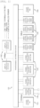
- FIG. 1 is a diagram illustrating an internal configuration of a triple redundant digital protective relay according to an embodiment of the present invention.
- the triple redundant digital protective relay may include power sources 110, power monitoring control devices 120, input/output contact point processing devices 130, a central communication device 140, a power/signal distribution device 150, and display operation devices 160.
- the power source 110 may convert AC 110 V or DC 125 V into low-voltage power suitable for internal circuit operations of the protective relay and supply electrical energy alone or in parallel.
- the power monitoring control device 120 may detect a voltage and a current of a power system, perform digital signal processing through analog-to-digital conversion, calculate various electricity quantities through a metering operation, monitor a failure of the power system through electricity quantity analysis, asymmetrically exchange information when a failure or abnormality occurs, derive a high-reliability determination result through a 2 out of 3 voting logic, and control a circuit breaker or other power devices.
- the power monitoring control device 120 may have a triple redundant structure. Specifically, the power monitoring control device may operate in a single mode which drives one module when an internal failure is defected from two modules, that is, power monitoring control devices, may operate in a dual redundant mode of a 2 out of 2 voting or a 1 out of 2 voting which drives two modules when an internal failure is detected from one module, and may operate in a triple redundant mode of a 2 out of 3 voting which drives three modules when no internal failure is detected.
- the input/output contact point processing device 130 may monitor an operating state of the power system at a digital input contact point, generate a control signal and an alarm signal of the protective relay at a digital output contact point to the outside, select up to four devices so as to be suitable for field application, and mount the selected devices on the protective relay.
- the central communication device 140 may acquire operating state data of the power system, various electricity quantity metering values, and events from the power monitoring control device 120 and the input/output contact point processing device 130, may record and manage the acquired information in a database, may transmit the information of the database via communication in response to a request from an external device outside the protective relay, or may receive a command from an external device via communication, transmit data to an internal device inside the protective device, and process the data.
- the power/signal distribution device 150 may be connected to the respective devices inside the protective relay, supply power to the respective devices, and perform communication and signal exchange between the respective devices.
- the display operation device 160 may communicate with the central communication device to acquire and display the operating state of the protective relay recorded in the database and the operating state of the power system detected by the protective relay.
- the display operation device 160 may include a button that allows a field user to issue a command to change operation characteristics of the protective relay or allows a field user to perform an operation for controlling the protective relay.
- FIG. 2 is a diagram illustrating an internal network configuration of the triple redundant digital protective relay.
- the central communication device may transmit and receive a variety of information while interworking with the power monitoring control devices by using Ethernet communication, and transmit and receive a variety of information while interworking between the power monitoring control devices or the input/output contact point processing devices by using CAN communication.
- Ethernet communication and the CAN communication have been described as an example, but the present invention is not necessarily limited thereto. If necessary, various communication schemes may be applied.
- FIG. 3 is a diagram illustrating a functional structure of the power monitoring control device illustrated in FIG. 1 .
- the power monitoring control device 120 may include a current transformer 121, a potential transformer 122, an A/D signal converter 123, a digital signal processor (DSP) 124, a central processing unit (CPU) 125, a first circuit breaker trip circuit 126, and a second circuit breaker trip circuit 127.
- DSP digital signal processor
- CPU central processing unit
- the current transformer 121 is also referred to as CT and may transform a current flowing through a power line into a current having a small magnitude which can be processed by the power monitoring control device.
- the potential transformer 122 is also referred to as PT and may transform a voltage of the power system into a low level voltage which can be detected by the power monitoring control device.
- the A/D signal converter 123 may receive a converted analog signal from the current transformer 121 and the potential transformer 122 and convert the received analog signal into a digital signal.
- the DSP 124 may perform signal processing on voltage and current signals of the power system, which are converted through the A/D signal converter, and perform various electricity quantity metering and measurement functions based on the signal processing result.
- the CPU 125 may monitor a health of the power system by using voltage, current, and various electricity quantity data received from the DSP 124, and detect failure or non-failure of the power system through various failure detection algorithms.
- the CPU 125 shares the result of monitoring the power system with other power monitoring control devices in real time.
- the CPU 125 When the failure of the power system is determined, the CPU 125 immediately transfers the determination result to the first circuit breaker trip circuit 126 and the second circuit breaker trip circuit 127 and performs a control function for promptly separating the failed system from the healthy system. In order for high-reliability failure monitoring and control, the CPU 125 shares the operation result information with other power monitoring control devices via dedicated communication by transmitting or receiving the operation result information. In a condition that all the three power monitoring control devices perform the normal operations without abnormality, the CPU 125 determines the operation result information of the other two power monitoring control devices other than the operation result information of one power monitoring control device through a 2 out of 3 voting mechanism, and controls a circuit breaker trip contact point 127a at which two control contact point devices are configured in series. A circuit breaker trip contact point 127b is controlled by a signal generated through a 2 out of 3 mechanism by another power monitoring control device.
- the first circuit breaker trip circuit 126 and the second circuit breaker trip circuit 127 may control the circuit breakers according to the control based on the operation result information of the power monitoring control device of the CPU 125.
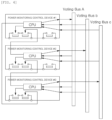
- FIG. 4 is a diagram illustrating a mutual connection relationship of the power monitoring control devices having a triple redundant structure.
- the power monitoring control devices having the triple redundant structure according to the present invention may share operation result information with one another by using voting buses by transmitting and receiving the operation result information.
- the power monitoring control device #1 transmits its own operation result information via a voting bus A, receives operation result information of the power monitoring control device #2 via a voting bus B, and receive operation result information of the power monitoring control device #3 via a voting bus C.
- the power monitoring control device #2 transmits its own operation result information via the voting bus B, receives operation result information of the power monitoring control device #1 via the voting bus A, and receive operation result information of the power monitoring control device #3 via the voting bus C.
- the power monitoring control device #3 transmits its own operation result information via the voting bus C, receives operation result information of the power monitoring control device #1 via the voting bus A, and receive operation result information of the power monitoring control device #2 via the voting bus B.
- FIG. 5 is a diagram illustrating the operation mechanism of the power monitoring control devices illustrated in FIG. 1 .
- the key operation of the triple redundant protective relay includes a protective relay algorithm operation that allows each of the power monitoring control devices to receive the voltage and current of the power system through the potential transformer and the current transformer, meters the quantity of electricity, monitors the operating state of the power system, and monitors and detects the failure of the power system, and any operations in which the state monitoring of the circuit breaker is performed, the result is exchanged via dedicated communication between the power monitoring control devices, each of the three power monitoring control devices compares its own determination result with the determination results of the other two power monitoring control devices through a 2 out of 3 voting logic, the determination results are evaluated as reliable when two or more determination results are identical to each other, the determination results are input to a user-defined logic function, and the power device is controlled by outputting control and alarm signals calculated as a user-defined logic operation result to the outside.
- a protective relay algorithm operation that allows each of the power monitoring control devices to receive the voltage and current of the power system through the potential transformer and the current transformer, meters the quantity of electricity, monitors the operating state of the power system, and monitor
- Each of the power monitoring control devices includes two output contact points for trip control of the power device, in particular, the circuit breaker.
- one contact point constitutes two signal relays in series.
- One of the two signal relays connected in series is controlled based on the power monitoring control device's own 2 out of 3 voting logic operation result, and the other signal relay is controlled based on a 2 out of voting logic operation result of another power monitoring control device.
- the external output is allowed only when the two signal relays operate. Risk factors that may cause the triple redundant protective relay to malfunction due to the failure of the single signal relay itself or the control circuit thereof are excluded.
- a signal for controlling a signal relay of another power monitoring control device is transmitted to an inner layer conductor of a printed circuit board (PCB) through a differential transmission device, the structure is robust against external noise or command mode noise that resonates with a switching frequency of a peripheral circuit.
- the signal for controlling the signal relay of another power monitoring control device is output in a valid state only when the 2 out of 3 voting trip operation result of the power monitoring control device that is a signal transmitter is true, this is also a structure that excludes a malfunction.
- a signal relay capable of being autonomously controlled may be incorrectly operated, and both the two signal relays may malfunction only when the failure or error occurs in another power monitoring control device that is another signal relay controller connected in series.
- This is for a security failure of a serial dual redundant mode and is a mode having a lowest security failure as compared with a single mode, a parallel dual redundant mode, and a serial/parallel triple redundant mode. It can be said that the possibility thereof is also low.
- Each of the power monitoring control devices generates two or more same determination results logically by a 2 out of 3 voting logic and outputs a control signal to the outside through an output contact point of a serial dual redundant configuration.
- a 2 out of 3 voting logic outputs a control signal to the outside through an output contact point of a serial dual redundant configuration.
- the 2 out of 3 voting logic operates only when the three power monitoring control devices are all in a healthy state, and the 2 out of 3 voting logic stops operating when a failure occurs in one power monitoring control device.
- the triple redundant protective relay may always perform inherent operation duty while maintaining high reliability.
- each of the power monitoring control devices separately includes a voltage and current detection circuit of the power system, and a state detection circuit and a control output circuit of the circuit breaker.
- an arithmetic operation device for performing a metering operation and a protective relay algorithm, a user-defined logic function for detecting a state of the power system and a state of the peripheral device and outputting a corresponding appropriate control, an event processing function capable of detecting an operation history and a failure history, a memory for recording, and a non-volatile memory for storing setup data for an optimal operation are included in each of the operation processing units, thereby excluding dependency on other devices.
- FIG. 6 is a diagram illustrating a configuration of an input/output contact point processing device according to an embodiment of the present invention.
- the input/output contact point processing device monitors an operating state of the power system and generates a control signal and an alarm signal of the protective relay to the outside.
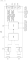
- FIG. 7 is a diagram illustrating a functional structure of a central communication device according to an embodiment of the present invention.
- the central communication device 140 may acquire operating state data and various electricity quantity metering values of the power system, events, and the like from the power monitoring control devices 120 and the input/output contact point processing devices 130, and record and manage the acquired information in the database.
- the central communication device 140 may transmit the information of the database in response to a request from an external device outside the protective relay, or receive a command from an external device via communication, transmit the information to an internal device of the protective relay based on the command, and process the information.
- FIG. 8 is a diagram illustrating a mutual relationship between the power monitoring control device and the central communication device.
- the central communication device may transmit and receive a variety of information while interworking with the power monitoring control devices having the triple redundant structure by using Ethernet communication.
- FIG. 9 is a diagram showing a method for operating a triple redundant digital protective relay, according to an embodiment of the present invention.
- the power monitoring control device may calculate various electricity quantities of a power system by detecting a voltage and a current of the power system and performing digital signal processing and metering operations through analog-to-digital conversion based on the detected voltage and current.
- the power monitoring control device may analyze the calculated electricity quantities and detect a failure or non-failure of the power system based on the analysis result.
- the power monitoring control device may share monitoring result information with other power monitoring control devices by interworking with other power monitoring control devices and transmitting or receiving the monitoring result information interwork to other power monitoring control devices via dedicated communication.
- the power monitoring control device may detect internal failure based on the shared monitoring result information. That is, the power monitoring control device may be set to a single mode that, when internal failure is detected in two power monitoring control devices, drives one power monitoring control device.
- the power monitoring control device may be set to a serial dual redundant mode of a 2 out of 2 voting or a parallel dual redundant mode of a 1 out of 1 voting that, when internal failure is detected in one power monitoring control device, drives two power monitoring control devices.
- the power monitoring control device may be set to a triple redundant mode of a 2 out of 3 voting that, when no internal failure is detected, drives three power monitoring control devices.
- the power monitoring control device may perform logic processing, for example, AND logic or OR logic processing on the detection result of the corresponding power monitoring control device according to the determined mode and make a final determination on the control of the circuit breaker based on the logic processing result.
- logic processing for example, AND logic or OR logic processing
- the power monitoring control device may control the circuit breaker according to the final determination.
- the present invention is not limited to the embodiments. That is, to the extent of the purpose of the present invention, all of such elements may be selectively coupled and operate as one or more elements. Such elements may be realized by each individual hardware, but all or part of such elements may be selectively combined into a computer program having a program module performing partial or all functions combined by single hardware or a plurality of hardware.
- Such computer program may be stored in computer readable media, such as USB memory, CD disk, or flash memory, and may be read and executed by the computer to thereby realize the embodiments of the present invention.
- the computer readable media for the computer program may include magnetic recording media, optical recording media, and carrier wave media.
Landscapes
- Engineering & Computer Science (AREA)
- Power Engineering (AREA)
- Emergency Protection Circuit Devices (AREA)
- Remote Monitoring And Control Of Power-Distribution Networks (AREA)
- Supply And Distribution Of Alternating Current (AREA)
Claims (6)
- Dreifach redundantes digitales Schutzrelais zur Steuerung eines Leistungsschalters, wobei das dreifach redundante digitale Schutzrelais Folgendes umfasst:drei Leistungsüberwachungs-Steuergeräte (120), die eine dreifach redundante Struktur definieren und einen Leistungsschalter steuern, um ein fehlerhaftes Stromsystem von einem fehlerfreien System auf der Grundlage einer 2-aus-3-Abstimmung unter Verwendung einer gegenseitigen Echtzeit-Datenkommunikation zu trennen; undein zentrales Kommunikationsgerät (140), das Daten bezüglich eines Betriebszustands des Stromsystems von den drei Leistungsüberwachungs-Steuergeräten (120) erfasst und die erfassten Daten bezüglich des Betriebszustands des Stromsystems verwaltet, um die verwalteten erfassten Daten als Reaktion auf eine Anforderung von einem externen Gerät außerhalb des Schutzrelais zu übertragen oder einen von einem externen Gerät außerhalb des Schutzrelais empfangenen Befehl zu verarbeiten,wobei jedes der drei Leistungsüberwachungs-Steuergeräte (120) umfasst:eine CPU (125), die den Leistungsschalter zum Trennen des ausgefallenen Stromsystems auf der Grundlage der 2-aus-3-Abstimmung unter Verwendung von Echtzeit-Datenkommunikation mit anderen Leistungsüberwachungs-Steuergeräten (120) steuert;einen ersten Leistungsschalter-Auslösestromkreis (126), der durch ein Signalrelais als Ausgangskontaktpunkt für eine erste Auslösesteuerung des Leistungsschalters gemäß einem ersten Steuersignal von der CPU (125) implementiert ist; undeinen zweiten Leistungsschalter-Auslösestromkreis (127), der durch zwei in Reihe geschaltete Signalrelais als Ausgangskontaktpunkt für eine zweite Auslösesteuerung des Leistungsschalters gemäß einem zweiten Steuersignal von der CPU (125) implementiert ist,wobei das Leistungsüberwachungs-Steuergerät (120) eines der beiden in Reihe geschalteten Signalrelais gemäß einem logischen Verknüpfungsergebnis davon auf der Grundlage der 2-aus-3-Abstimmung steuert und das andere Signalrelais gemäß einem logischen Verknüpfungsergebnis auf der Grundlage der 2-aus-3-Abstimmung eines anderen Leistungsüberwachungs-Steuergeräts (120) steuert,wobei, wenn der Ausfall des Stromsystems festgestellt wird, die CPU (125) das Feststellungsergebnis sofort an den ersten Leistungsschalter-Auslösestromkreis (126) und den zweiten Leistungsschalter-Auslösestromkreis (127) überträgt und eine Steuerfunktion zum sofortigen Trennen des ausgefallenen Systems von dem gesunden System ausführt,wobei die CPU (125) die Betriebsergebnisinformationen mit anderen Leistungsüberwachungs-Steuergeräten über eine dedizierte Kommunikation durch Senden oder Empfangen der Betriebsergebnisinformationen teilt, wobei die 2-aus-3-Abstimmung die von jedem der drei Leistungsüberwachungs-Steuergeräte (120) bereitgestellten und geteilten Betriebsergebnisinformationen umfasst,wobei in einem Zustand, in dem alle drei Leistungsüberwachungs-Steuergeräte den normalen Betrieb ohne Anomalie ausführen, die CPU (125) die Betriebsergebnisinformationen der anderen beiden Leistungsüberwachungs-Steuergeräte, die nicht die Betriebsergebnisinformationen eines Leistungsüberwachungs-Steuergeräts sind, durch den 2-aus-3-Abstimmungsmechanismus bestimmt und einen ersten Schaltungsunterbrecher-Auslösekontaktpunkt (127a) steuert,wobei ein zweiter Auslösekontaktpunkt (127b) des Leistungsschalters durch ein Signal gesteuert wird, das durch den 2-aus-3-Mechanismus von einem anderen Leistungsüberwachungs-Steuergerät erzeugt wird,wobei in einem Fall, in dem ein Fehler in dem Auslösekontaktpunkt (127a oder 127b) des Leistungsschalters auftritt, wenn ein Fehler in einem anderen Leistungsüberwachungs-Steuergerät auftritt, die eine gegenseitige Steuerbeziehung aufweist, oder wenn ein Fehler in einem Übertragungs- und Empfangspfad für Betriebsergebnisinformationen selbst auftritt, drei Leistungsüberwachungs-Steuergeräte und Peripherievorrichtungen in einem fehlerhaften Zustand sind,wobei in diesem Fall das Bestimmungsergebnis des ausgefallenen Leistungsüberwachungs-Steuergerätes ignoriert wird, eine UND-Logikoperation oder eine ODER-Logikoperation auf dem Ergebnis des Leistungsüberwachungs-Steuergerätes selbst oder dem Betriebsergebnis eines anderen fehlerfreien Leistungsüberwachungs-Steuergerätes durchgeführt wird, eine endgültige Bestimmung durch die Ausgabe der Logik erfolgt und der Leistungsschalter durch den ersten Leistungsschalter-Auslösestromkreis (126) gesteuert wird.
- Dreifach redundantes digitales Schutzrelais nach Anspruch 1, wobei das Leistungsüberwachungs-Steuergerät (120) das eine Signalrelais des ersten Leistungsschalter-Auslösestromkreises (126) gemäß einem logischen Operationsergebnis davon auf der Grundlage einer 1-aus-2- oder einer 2-aus-2-Abstimmung steuert.
- Dreifach redundantes digitales Schutzrelais nach Anspruch 2, wobei, wenn ein Fehler im Stromsystem auftritt und ein interner Fehler von einer der drei Leistungsüberwachungs-Steuergeräte (120) erfasst wird, das Leistungsüberwachungs-Steuergerät (120) den Leistungsschalter unter Verwendung der logischen Operation auf der Grundlage der 1-aus-2-Abstimmung oder der 2-aus-2-Abstimmung steuert.
- Dreifach redundantes digitales Schutzrelais nach Anspruch 1, wobei das Leistungsüberwachungs-Steuergerät einen Ausfall oder Nichtausfall des Stromsystems auf der Grundlage einer auf einer Spannung und einem Strom basierenden Elektrizitätsmenge erkennt und ein Erkennungsergebnis an andere Leistungsüberwachungs-Steuergeräte (120) unter Verwendung eines Abstimmungsbusses überträgt, um das Erkennungsergebnis mit den anderen Leistungsüberwachungs-Steuergeräten (120) zu teilen.
- Verfahren zum Betreiben eines dreifach redundanten digitalen Schutzrelais zum Steuern eines Leistungsschalters, wobei das Verfahren umfasst:Erfassen eines Ausfalls oder Nichtausfalls eines Stromsystems auf der Grundlage einer auf der Grundlage einer Spannung und eines Stroms berechneten Elektrizitätsmenge;Steuern eines Leistungsschalters zum Trennen eines ausgefallenen Stromsystems von einem fehlerfreien System auf der Grundlage einer 2-aus-3-Abstimmung unter Verwendung einer gegenseitigen Echtzeit-Datenkommunikation über drei Leistungsüberwachungs-Steuergeräte (120), die eine dreifach redundante Struktur aufweisen; undErfassen von Daten bezüglich eines Betriebszustands des Stromsystems von den drei Leistungsüberwachungs-Steuergeräten (120) und Verwalten der erfassten Daten bezüglich des Betriebszustands des Stromsystems, um die verwalteten erfassten Daten als Antwort auf eine Anforderung von einem externen Gerät außerhalb des Schutzrelais zu übertragen und einen von einem externen Gerät außerhalb des Schutzrelais empfangenen Befehl zu verarbeiten,wobei jedes der drei Leistungsüberwachungs-Steuergeräte (120) umfasst:eine CPU (125), die den Leistungsschalter zum Trennen des ausgefallenen Stromsystems auf der Grundlage der 2-aus-3-Abstimmung unter Verwendung von Echtzeit-Datenkommunikation mit anderen Leistungsüberwachungs-Steuergeräten (120) steuert;einen ersten Leistungsschalter-Auslösestromkreis (126), der durch ein Signalrelais als Ausgangskontaktpunkt für eine erste Auslösesteuerung des Leistungsschalters gemäß einem ersten Steuersignal von der CPU (125) implementiert ist; undeinen zweiten Leistungsschalter-Auslösestromkreis (127), der durch zwei in Reihe geschaltete Signalrelais als Ausgangskontaktpunkt für eine zweite Auslösesteuerung des Leistungsschalters gemäß einem zweiten Steuersignal von der CPU (125) implementiert ist,wobei das Leistungsüberwachungs-Steuergerät (120) eines der beiden in Reihe geschalteten Signalrelais gemäß einem logischen Verknüpfungsergebnis davon auf der Grundlage der 2-aus-3-Abstimmung steuert und das andere Signalrelais gemäß einem logischen Verknüpfungsergebnis auf der Grundlage der 2-aus-3-Abstimmung eines anderen Leistungsüberwachungs-Steuergeräts steuert.wobei, wenn der Ausfall des Stromsystems festgestellt wird, die CPU (125) das Feststellungsergebnis sofort an den ersten Leistungsschalter-Auslösestromkreis (126) und den zweiten Leistungsschalter-Auslösestromkreis (127) überträgt und eine Steuerfunktion zum sofortigen Trennen des ausgefallenen Systems vom gesunden System ausführt,wobei die CPU (125) die Betriebsergebnisinformationen mit anderen Leistungsüberwachungs-Steuergeräten über eine dedizierte Kommunikation durch Senden oder Empfangen der Betriebsergebnisinformationen teilt, wobei die 2-aus-3-Abstimmung die von jedem der drei Leistungsüberwachungs-Steuergeräte (120) bereitgestellten und geteilten Betriebsergebnisinformationen umfasst,wobei in einem Zustand, in dem alle drei Leistungsüberwachungs-Steuergeräte den normalen Betrieb ohne Anomalie ausführen, die CPU (125) die Betriebsergebnisinformationen der anderen beiden Leistungsüberwachungs-Steuergeräte, die nicht die Betriebsergebnisinformationen eines Leistungsüberwachungs-Steuergeräts sind, durch den 2-aus-3-Abstimmungsmechanismus bestimmt und einen ersten Schaltkontaktpunkt (127a) steuert,wobei ein zweiter Auslösekontaktpunkt (127b) des Leistungsschalters durch ein Signal gesteuert wird, das durch den 2-aus-3-Mechanismus von einem anderen Leistungsüberwachungs-Steuergerät erzeugt wird,wobei in einem Fall, in dem ein Fehler in dem Auslösekontaktpunkt (127a oder 127b) des Leistungsschalters auftritt, wenn ein Fehler in einem anderen Leistungsüberwachungs-Steuergerät auftritt, die eine gegenseitige Steuerbeziehung aufweist, oder wenn ein Fehler in einem Übertragungs- und Empfangspfad für Betriebsergebnisinformationen selbst auftritt, drei Leistungsüberwachungs-Steuergeräte und Peripherievorrichtungen in einem fehlerhaften Zustand sind,wobei in diesem Fall das Bestimmungsergebnis des ausgefallenen Leistungsüberwachungs-Steuergeräts ignoriert wird, eine UND-Logikoperation oder eine ODER-Logikoperation auf dem Ergebnis des Leistungsüberwachungs-Steuergeräts selbst oder dem Betriebsergebnis einem anderen fehlerfreien Leistungsüberwachungs-Steuergeräts durchgeführt wird, eine endgültige Bestimmung durch die Ausgabe der Logik erfolgt und der Leistungsschalter durch den ersten Leistungsschalter-Auslösestromkreis (126) gesteuert wird.
- Verfahren nach Anspruch 5, wobei, wenn ein Fehler im Stromsystem auftritt und ein interner Fehler von einem der drei Leistungsüberwachungs-Steuergeräte (120) erkannt wird, die Steuerung die Steuerung des Leistungsschalters durch Verwendung einer logischen Operation auf der Grundlage einer 1-aus-2-Abstimmung oder einer 2-aus-2-Abstimmung umfasst.
Applications Claiming Priority (2)
| Application Number | Priority Date | Filing Date | Title |
|---|---|---|---|
| KR1020140180115A KR101552852B1 (ko) | 2014-12-15 | 2014-12-15 | 3중화 디지털 보호 계전기 및 그 운영 방법 |
| PCT/KR2015/013589 WO2016099083A1 (ko) | 2014-12-15 | 2015-12-11 | 3중화 디지털 보호 계전기 및 그 운영 방법 |
Publications (4)
| Publication Number | Publication Date |
|---|---|
| EP3236552A1 EP3236552A1 (de) | 2017-10-25 |
| EP3236552A4 EP3236552A4 (de) | 2018-09-19 |
| EP3236552C0 EP3236552C0 (de) | 2025-02-12 |
| EP3236552B1 true EP3236552B1 (de) | 2025-02-12 |
Family
ID=54248192
Family Applications (1)
| Application Number | Title | Priority Date | Filing Date |
|---|---|---|---|
| EP15870250.6A Active EP3236552B1 (de) | 2014-12-15 | 2015-12-11 | Dreifach redundantes digitales schutzrelais und betriebsverfahren dafür |
Country Status (5)
| Country | Link |
|---|---|
| US (1) | US10158220B2 (de) |
| EP (1) | EP3236552B1 (de) |
| KR (1) | KR101552852B1 (de) |
| CN (1) | CN107408808B (de) |
| WO (1) | WO2016099083A1 (de) |
Families Citing this family (21)
| Publication number | Priority date | Publication date | Assignee | Title |
|---|---|---|---|---|
| JP6786449B2 (ja) * | 2017-06-29 | 2020-11-18 | ルネサスエレクトロニクス株式会社 | 半導体装置 |
| KR101998295B1 (ko) | 2017-12-28 | 2019-07-10 | 주식회사 제니스텍 | 고속 직렬 버스를 갖는 다중 저장 메모리 공유 방식의 전력 제어 시스템 |
| KR101883735B1 (ko) | 2018-01-15 | 2018-07-31 | 이에스피 주식회사 | 출력 접점 감시 기능의 3중화 보호 장치 |
| JP2019159992A (ja) * | 2018-03-15 | 2019-09-19 | ルネサスエレクトロニクス株式会社 | 機能安全システム、機能安全システムの安全制御方法及び機能安全プログラム |
| JP6987013B2 (ja) * | 2018-04-11 | 2021-12-22 | 三菱電機株式会社 | ディジタル保護制御装置 |
| TWI687013B (zh) * | 2018-11-06 | 2020-03-01 | 陳錫瑜 | 斷路器斷電跳脫裝置 |
| TWI687012B (zh) * | 2018-11-06 | 2020-03-01 | 陳錫瑜 | 斷路器跳脫迴路系統改良裝置 |
| TWI687014B (zh) * | 2018-11-06 | 2020-03-01 | 陳錫瑜 | 交流系統電容跳脫裝置改良裝置 |
| CN109450078B (zh) * | 2018-12-24 | 2024-07-05 | 徐州海伦哲特种车辆有限公司 | 一种双冗余ups电源车及其控制方法 |
| CN109861185A (zh) * | 2019-01-24 | 2019-06-07 | 许继集团有限公司 | 一种继电保护设备控制方法及装置 |
| CN109962528B (zh) * | 2019-02-28 | 2021-07-06 | 国家电网有限公司 | 一种变电站二次设备智能管控系统 |
| KR102790970B1 (ko) * | 2020-04-10 | 2025-04-04 | 엘에스일렉트릭(주) | 원격 단말 장치 및 원격 단말 장치 시스템 |
| CN112147498A (zh) * | 2020-09-23 | 2020-12-29 | 广州市扬新技术研究有限责任公司 | 一种直流断路器监视和控制的模块 |
| CN112526979B (zh) * | 2020-12-16 | 2023-06-09 | 中国兵器装备集团自动化研究所 | 一种多重冗余架构的串行通信接口诊断系统及方法 |
| CN113085954B (zh) * | 2021-04-08 | 2022-05-17 | 中车青岛四方机车车辆股份有限公司 | 一种轨道车辆用逻辑控制系统生成方法及相应系统 |
| CN114093140A (zh) * | 2021-10-18 | 2022-02-25 | 中核核电运行管理有限公司 | 一种核电厂变压器瓦斯继电器报警系统 |
| CN114123284B (zh) * | 2021-11-25 | 2024-10-22 | 中国三峡建工(集团)有限公司 | 一种海上风电柔性直流输电紧凑化控制保护系统 |
| CN115359932B (zh) * | 2022-08-19 | 2023-09-26 | 中国核动力研究设计院 | P11非允许信号生成装置和方法、核电厂用相关系统 |
| CN115817247A (zh) * | 2022-11-21 | 2023-03-21 | 浙江万马新能源有限公司 | 一种充电桩容灾充电方法、系统、设备和介质 |
| US12603490B2 (en) * | 2023-11-01 | 2026-04-14 | Schweitzer Engineering Laboratories, Inc. | Protective device with multi-channel line current differential protection |
| CN120029098B (zh) * | 2023-11-23 | 2026-04-17 | 南京南瑞继保电气有限公司 | 一种三重冗余的模拟量输入自诊断方法及装置 |
Citations (1)
| Publication number | Priority date | Publication date | Assignee | Title |
|---|---|---|---|---|
| EP0275362B1 (de) * | 1986-07-04 | 1994-07-13 | Hitachi, Ltd. | Sicherheitssteuersystem |
Family Cites Families (15)
| Publication number | Priority date | Publication date | Assignee | Title |
|---|---|---|---|---|
| US4926281A (en) * | 1989-02-27 | 1990-05-15 | Triplex | Fail-safe and fault-tolerant alternating current output circuit |
| JP3207388B2 (ja) | 1998-04-17 | 2001-09-10 | 株式会社東芝 | 電力系統保護制御装置、電力系統監視制御システムおよびプログラムを記憶した記憶媒体 |
| US6496342B1 (en) * | 1999-02-12 | 2002-12-17 | Bitronics Inc. | Distributed monitoring and protection system for a distributed power network |
| US6550018B1 (en) * | 2000-02-18 | 2003-04-15 | The University Of Akron | Hybrid multiple redundant computer system |
| US20040010350A1 (en) * | 2000-05-31 | 2004-01-15 | Per-Anders Lof | Distributed power generation system protection scheme |
| KR100380658B1 (ko) | 2001-01-31 | 2003-04-18 | 한국전력공사 | 삼중화 제어장치의 직렬통신을 이용한 출력장치와 그제어방법 |
| JP4074223B2 (ja) | 2003-06-10 | 2008-04-09 | 株式会社東芝 | ディジタル保護継電器 |
| KR100807342B1 (ko) * | 2007-03-13 | 2008-02-28 | 와이피피디지텍(주) | 개별 계전기의 보호요소 동작신호를 사용한 3중화 보호 시스템 |
| KR101036544B1 (ko) * | 2008-06-27 | 2011-05-24 | 이만실 | 전력계통의 차단기 감시 장치 |
| CN101673936A (zh) | 2008-09-11 | 2010-03-17 | 华东电力试验研究院有限公司 | 保护系统 |
| KR100990736B1 (ko) | 2010-05-25 | 2010-10-29 | 주식회사 파워토스 | 보호 배전반의 상태를 감시하고 제어하는 보호 시스템 |
| CN201916175U (zh) | 2011-01-05 | 2011-08-03 | 董南南 | 空气压缩机超速保护装置 |
| CN203444293U (zh) | 2013-06-25 | 2014-02-19 | 新华控制工程有限公司 | 三重冗余紧急停机装置 |
| US9615440B2 (en) * | 2013-10-04 | 2017-04-04 | Toshiba Mitsubishi-Electric Industrial Systems Corporation | Power supply apparatus outputting alternating-current voltage to plasma generator |
| US9603282B2 (en) * | 2014-01-03 | 2017-03-21 | Microsoft Technology Licensing, Llc | Datacenter and cooling control fault-tolerance using compute resources |
-
2014
- 2014-12-15 KR KR1020140180115A patent/KR101552852B1/ko active Active
-
2015
- 2015-12-11 US US15/535,364 patent/US10158220B2/en active Active
- 2015-12-11 WO PCT/KR2015/013589 patent/WO2016099083A1/ko not_active Ceased
- 2015-12-11 CN CN201580073132.XA patent/CN107408808B/zh active Active
- 2015-12-11 EP EP15870250.6A patent/EP3236552B1/de active Active
Patent Citations (1)
| Publication number | Priority date | Publication date | Assignee | Title |
|---|---|---|---|---|
| EP0275362B1 (de) * | 1986-07-04 | 1994-07-13 | Hitachi, Ltd. | Sicherheitssteuersystem |
Also Published As
| Publication number | Publication date |
|---|---|
| US10158220B2 (en) | 2018-12-18 |
| KR101552852B1 (ko) | 2015-09-14 |
| CN107408808A (zh) | 2017-11-28 |
| WO2016099083A9 (ko) | 2016-08-11 |
| EP3236552A1 (de) | 2017-10-25 |
| CN107408808B (zh) | 2019-12-10 |
| EP3236552C0 (de) | 2025-02-12 |
| US20170365992A1 (en) | 2017-12-21 |
| EP3236552A4 (de) | 2018-09-19 |
| WO2016099083A1 (ko) | 2016-06-23 |
Similar Documents
| Publication | Publication Date | Title |
|---|---|---|
| EP3236552B1 (de) | Dreifach redundantes digitales schutzrelais und betriebsverfahren dafür | |
| ES2941889T3 (es) | Sistema de distribución eléctrica fiable con fuente de potencia alternativa | |
| EP3001535B1 (de) | Schutzsteuerungssystem für einen prozessbus, zusammenführungseinheit und berechnungsvorrichtung | |
| CN104124757B (zh) | 高海拔光伏电站电网故障模拟检测设备后台操作监控系统 | |
| Panteli et al. | Quantifying the reliability level of system integrity protection schemes | |
| JP5968193B2 (ja) | マージングユニットおよび解析システム | |
| EP4404407A1 (de) | Datenverarbeitungssystem und datenverarbeitungsverfahren für ein unterstationssystem und unterstation für ein elektrisches stromsystem | |
| KR102402548B1 (ko) | 자동 감시 및 분석 구조의 전력 설비 보호 계통 진단 시스템 | |
| Panteli et al. | Design of dependable and secure system integrity protection schemes | |
| US11112466B2 (en) | Equipment failure detection in an electric power system | |
| JP2013106456A (ja) | 保護継電器 | |
| JP5752845B2 (ja) | 統合ユニット及び保護リレーシステム | |
| Prudenzi et al. | Smartening hospital electrical distribution for enhancing resilience | |
| KR101631631B1 (ko) | 보호계전기의 고장진단 및 복구방법 | |
| CN111525520B (zh) | 一种事故总或保护方法、装置、设备及存储介质 | |
| Schmeling et al. | The detector safety system for LHC experiments | |
| Naik et al. | Smart grid communication protocol test automation along with protection test automation | |
| Dustegor et al. | A distributed fault protection method for power grid with high penetration of renewable energy sources | |
| KR20140122484A (ko) | 배전 감시진단보호 시스템 | |
| Panteli et al. | Reliability assessment of SIPS based on a safety integrity level and spurious trip level | |
| JP7792865B2 (ja) | デジタル保護リレーおよびその保全管理システム | |
| Zimmerman et al. | How disruptions in DC power and communications circuits can affect protection | |
| KR102673587B1 (ko) | 디지털 변전소 취약성 해소를 위한 통합 예비 제어 감시 시스템 및 방법 | |
| Thompson | Integrated Protection and Control Systems with Continuous Self-Testing | |
| Liu et al. | Risk assessment of an IEC 61850 based substation communication network in a system integrity protection scheme |
Legal Events
| Date | Code | Title | Description |
|---|---|---|---|
| STAA | Information on the status of an ep patent application or granted ep patent |
Free format text: STATUS: THE INTERNATIONAL PUBLICATION HAS BEEN MADE |
|
| PUAI | Public reference made under article 153(3) epc to a published international application that has entered the european phase |
Free format text: ORIGINAL CODE: 0009012 |
|
| STAA | Information on the status of an ep patent application or granted ep patent |
Free format text: STATUS: REQUEST FOR EXAMINATION WAS MADE |
|
| 17P | Request for examination filed |
Effective date: 20170717 |
|
| AK | Designated contracting states |
Kind code of ref document: A1 Designated state(s): AL AT BE BG CH CY CZ DE DK EE ES FI FR GB GR HR HU IE IS IT LI LT LU LV MC MK MT NL NO PL PT RO RS SE SI SK SM TR |
|
| AX | Request for extension of the european patent |
Extension state: BA ME |
|
| DAV | Request for validation of the european patent (deleted) | ||
| DAX | Request for extension of the european patent (deleted) | ||
| A4 | Supplementary search report drawn up and despatched |
Effective date: 20180821 |
|
| RIC1 | Information provided on ipc code assigned before grant |
Ipc: H02H 3/05 20060101AFI20180815BHEP |
|
| STAA | Information on the status of an ep patent application or granted ep patent |
Free format text: STATUS: EXAMINATION IS IN PROGRESS |
|
| 17Q | First examination report despatched |
Effective date: 20210714 |
|
| GRAP | Despatch of communication of intention to grant a patent |
Free format text: ORIGINAL CODE: EPIDOSNIGR1 |
|
| STAA | Information on the status of an ep patent application or granted ep patent |
Free format text: STATUS: GRANT OF PATENT IS INTENDED |
|
| RIC1 | Information provided on ipc code assigned before grant |
Ipc: H02H 7/26 20060101ALI20241031BHEP Ipc: H02H 1/00 20060101ALI20241031BHEP Ipc: H02H 3/05 20060101AFI20241031BHEP |
|
| INTG | Intention to grant announced |
Effective date: 20241129 |
|
| GRAS | Grant fee paid |
Free format text: ORIGINAL CODE: EPIDOSNIGR3 |
|
| GRAA | (expected) grant |
Free format text: ORIGINAL CODE: 0009210 |
|
| STAA | Information on the status of an ep patent application or granted ep patent |
Free format text: STATUS: THE PATENT HAS BEEN GRANTED |
|
| AK | Designated contracting states |
Kind code of ref document: B1 Designated state(s): AL AT BE BG CH CY CZ DE DK EE ES FI FR GB GR HR HU IE IS IT LI LT LU LV MC MK MT NL NO PL PT RO RS SE SI SK SM TR |
|
| REG | Reference to a national code |
Ref country code: GB Ref legal event code: FG4D |
|
| REG | Reference to a national code |
Ref country code: CH Ref legal event code: EP |
|
| REG | Reference to a national code |
Ref country code: DE Ref legal event code: R096 Ref document number: 602015091009 Country of ref document: DE |
|
| REG | Reference to a national code |
Ref country code: IE Ref legal event code: FG4D |
|
| U01 | Request for unitary effect filed |
Effective date: 20250312 |
|
| U07 | Unitary effect registered |
Designated state(s): AT BE BG DE DK EE FI FR IT LT LU LV MT NL PT RO SE SI Effective date: 20250320 |
|
| PG25 | Lapsed in a contracting state [announced via postgrant information from national office to epo] |
Ref country code: RS Free format text: LAPSE BECAUSE OF FAILURE TO SUBMIT A TRANSLATION OF THE DESCRIPTION OR TO PAY THE FEE WITHIN THE PRESCRIBED TIME-LIMIT Effective date: 20250512 |
|
| PG25 | Lapsed in a contracting state [announced via postgrant information from national office to epo] |
Ref country code: PL Free format text: LAPSE BECAUSE OF FAILURE TO SUBMIT A TRANSLATION OF THE DESCRIPTION OR TO PAY THE FEE WITHIN THE PRESCRIBED TIME-LIMIT Effective date: 20250212 |
|
| PG25 | Lapsed in a contracting state [announced via postgrant information from national office to epo] |
Ref country code: ES Free format text: LAPSE BECAUSE OF FAILURE TO SUBMIT A TRANSLATION OF THE DESCRIPTION OR TO PAY THE FEE WITHIN THE PRESCRIBED TIME-LIMIT Effective date: 20250212 |
|
| PG25 | Lapsed in a contracting state [announced via postgrant information from national office to epo] |
Ref country code: IS Free format text: LAPSE BECAUSE OF FAILURE TO SUBMIT A TRANSLATION OF THE DESCRIPTION OR TO PAY THE FEE WITHIN THE PRESCRIBED TIME-LIMIT Effective date: 20250612 Ref country code: NO Free format text: LAPSE BECAUSE OF FAILURE TO SUBMIT A TRANSLATION OF THE DESCRIPTION OR TO PAY THE FEE WITHIN THE PRESCRIBED TIME-LIMIT Effective date: 20250512 |
|
| PG25 | Lapsed in a contracting state [announced via postgrant information from national office to epo] |
Ref country code: HR Free format text: LAPSE BECAUSE OF FAILURE TO SUBMIT A TRANSLATION OF THE DESCRIPTION OR TO PAY THE FEE WITHIN THE PRESCRIBED TIME-LIMIT Effective date: 20250212 |
|
| PG25 | Lapsed in a contracting state [announced via postgrant information from national office to epo] |
Ref country code: GR Free format text: LAPSE BECAUSE OF FAILURE TO SUBMIT A TRANSLATION OF THE DESCRIPTION OR TO PAY THE FEE WITHIN THE PRESCRIBED TIME-LIMIT Effective date: 20250513 |
|
| PG25 | Lapsed in a contracting state [announced via postgrant information from national office to epo] |
Ref country code: SM Free format text: LAPSE BECAUSE OF FAILURE TO SUBMIT A TRANSLATION OF THE DESCRIPTION OR TO PAY THE FEE WITHIN THE PRESCRIBED TIME-LIMIT Effective date: 20250212 |
|
| PG25 | Lapsed in a contracting state [announced via postgrant information from national office to epo] |
Ref country code: CZ Free format text: LAPSE BECAUSE OF FAILURE TO SUBMIT A TRANSLATION OF THE DESCRIPTION OR TO PAY THE FEE WITHIN THE PRESCRIBED TIME-LIMIT Effective date: 20250212 |
|
| PG25 | Lapsed in a contracting state [announced via postgrant information from national office to epo] |
Ref country code: SK Free format text: LAPSE BECAUSE OF FAILURE TO SUBMIT A TRANSLATION OF THE DESCRIPTION OR TO PAY THE FEE WITHIN THE PRESCRIBED TIME-LIMIT Effective date: 20250212 |
|
| PLBE | No opposition filed within time limit |
Free format text: ORIGINAL CODE: 0009261 |
|
| STAA | Information on the status of an ep patent application or granted ep patent |
Free format text: STATUS: NO OPPOSITION FILED WITHIN TIME LIMIT |
|
| 26N | No opposition filed |
Effective date: 20251113 |
|
| U20 | Renewal fee for the european patent with unitary effect paid |
Year of fee payment: 11 Effective date: 20260102 |