EP3236101B1 - Kupplungsbaugruppe - Google Patents
Kupplungsbaugruppe Download PDFInfo
- Publication number
- EP3236101B1 EP3236101B1 EP16166127.7A EP16166127A EP3236101B1 EP 3236101 B1 EP3236101 B1 EP 3236101B1 EP 16166127 A EP16166127 A EP 16166127A EP 3236101 B1 EP3236101 B1 EP 3236101B1
- Authority
- EP
- European Patent Office
- Prior art keywords
- clutch
- disc
- holding brake
- assembly according
- operational assembly
- Prior art date
- Legal status (The legal status is an assumption and is not a legal conclusion. Google has not performed a legal analysis and makes no representation as to the accuracy of the status listed.)
- Active
Links
Images


Classifications
-
- F—MECHANICAL ENGINEERING; LIGHTING; HEATING; WEAPONS; BLASTING
- F16—ENGINEERING ELEMENTS AND UNITS; GENERAL MEASURES FOR PRODUCING AND MAINTAINING EFFECTIVE FUNCTIONING OF MACHINES OR INSTALLATIONS; THERMAL INSULATION IN GENERAL
- F16D—COUPLINGS FOR TRANSMITTING ROTATION; CLUTCHES; BRAKES
- F16D67/00—Combinations of couplings and brakes; Combinations of clutches and brakes
- F16D67/02—Clutch-brake combinations
- F16D67/04—Clutch-brake combinations fluid actuated
-
- F—MECHANICAL ENGINEERING; LIGHTING; HEATING; WEAPONS; BLASTING
- F16—ENGINEERING ELEMENTS AND UNITS; GENERAL MEASURES FOR PRODUCING AND MAINTAINING EFFECTIVE FUNCTIONING OF MACHINES OR INSTALLATIONS; THERMAL INSULATION IN GENERAL
- F16D—COUPLINGS FOR TRANSMITTING ROTATION; CLUTCHES; BRAKES
- F16D25/00—Fluid-actuated clutches
- F16D25/12—Details not specific to one of the before-mentioned types
-
- B—PERFORMING OPERATIONS; TRANSPORTING
- B63—SHIPS OR OTHER WATERBORNE VESSELS; RELATED EQUIPMENT
- B63H—MARINE PROPULSION OR STEERING
- B63H23/00—Transmitting power from propulsion power plant to propulsive elements
- B63H23/30—Transmitting power from propulsion power plant to propulsive elements characterised by use of clutches
-
- F—MECHANICAL ENGINEERING; LIGHTING; HEATING; WEAPONS; BLASTING
- F16—ENGINEERING ELEMENTS AND UNITS; GENERAL MEASURES FOR PRODUCING AND MAINTAINING EFFECTIVE FUNCTIONING OF MACHINES OR INSTALLATIONS; THERMAL INSULATION IN GENERAL
- F16D—COUPLINGS FOR TRANSMITTING ROTATION; CLUTCHES; BRAKES
- F16D13/00—Friction clutches
- F16D13/22—Friction clutches with axially-movable clutching members
- F16D13/38—Friction clutches with axially-movable clutching members with flat clutching surfaces, e.g. discs
- F16D13/52—Clutches with multiple lamellae ; Clutches in which three or more axially moveable members are fixed alternately to the shafts to be coupled and are pressed from one side towards an axially-located member
-
- F—MECHANICAL ENGINEERING; LIGHTING; HEATING; WEAPONS; BLASTING
- F16—ENGINEERING ELEMENTS AND UNITS; GENERAL MEASURES FOR PRODUCING AND MAINTAINING EFFECTIVE FUNCTIONING OF MACHINES OR INSTALLATIONS; THERMAL INSULATION IN GENERAL
- F16D—COUPLINGS FOR TRANSMITTING ROTATION; CLUTCHES; BRAKES
- F16D13/00—Friction clutches
- F16D13/58—Details
- F16D13/72—Features relating to cooling
-
- F—MECHANICAL ENGINEERING; LIGHTING; HEATING; WEAPONS; BLASTING
- F16—ENGINEERING ELEMENTS AND UNITS; GENERAL MEASURES FOR PRODUCING AND MAINTAINING EFFECTIVE FUNCTIONING OF MACHINES OR INSTALLATIONS; THERMAL INSULATION IN GENERAL
- F16D—COUPLINGS FOR TRANSMITTING ROTATION; CLUTCHES; BRAKES
- F16D13/00—Friction clutches
- F16D13/58—Details
- F16D13/74—Features relating to lubrication
-
- F—MECHANICAL ENGINEERING; LIGHTING; HEATING; WEAPONS; BLASTING
- F16—ENGINEERING ELEMENTS AND UNITS; GENERAL MEASURES FOR PRODUCING AND MAINTAINING EFFECTIVE FUNCTIONING OF MACHINES OR INSTALLATIONS; THERMAL INSULATION IN GENERAL
- F16D—COUPLINGS FOR TRANSMITTING ROTATION; CLUTCHES; BRAKES
- F16D25/00—Fluid-actuated clutches
- F16D25/12—Details not specific to one of the before-mentioned types
- F16D25/123—Details not specific to one of the before-mentioned types in view of cooling and lubrication
Definitions
- the present invention relates to an operating assembly for mechanically connecting an engine to a work machine.
- Such operating assemblies are sufficiently known in the prior art.
- a prime mover is usually connected to a drive shaft unit, and a work machine is connected to an output shaft unit. It is known, between drive shaft unit and output shaft unit z.
- B. to use hydraulically operated multi-plate clutches. Since it is known that, depending on the operating state of the device, multi-disc clutches may also transmit undesirable drag torques - this is particularly the case with oil-lubricated multi-disc clutches - a holding brake may be used in the area of an output shaft unit or output shaft in order to finally lock the machine.
- Units of this type are used in various applications, for example in maritime applications between diesel aggregates and propeller systems, but also in power generator units and the like.
- An example is in the document DE10 2015 114926 A1 shown.
- Multi-disc clutches are also known assemblies in which multi-disc discs connected directly or indirectly to a drive shaft rotate with respect to discs fixed on the housing side. These disk packs can be moved in the axial direction against spring force or other pre-tensioning, for example by means of hydraulic force, so that the distance between the rotating and stationary disks can be varied. With full contact, power is transmitted (speed x torque), with complete separation in an end position offering sufficient distance, the drive and output are separated from each other. Intermediate stages can be controlled with conventional systems by appropriate control of the pressure medium.
- the drive shaft of the coupling unit is set in rotation.
- pressure medium z. B. pressure oil By applying pressure by means of pressure medium z. B. pressure oil, the multi-plate clutch is engaged and thus enables a corresponding transmission of the rotation.
- the cooling capacity is accordingly of great importance.
- the resulting power loss in slipping operation is removed from the clutch via the internally supplied amount of oil.
- This energy input must be removed from the system via a cooler. This usually happens via a water-oil heat exchanger.
- the amount of oil made available on the clutch side is correspondingly decisive. Large quantities of oil are required to dissipate high power losses. Since, however, in practical operation of the units it cannot be determined in advance when the maximum power loss will occur, a correspondingly large amount of cooling oil must be available. However, when the clutch is disengaged, this large amount of oil leads to high drag torques which can lead to correspondingly high speeds on the output side. As a rule, however, these speeds are undesirable when the clutch is open. The goal would be the infinitely variable speed setting down to zero.
- a possible remedy is a holding brake with which the output side is finally locked. However, there remains an uncontrollable speed range.
- the present invention is based on the TASK of providing an operating assembly of the generic type with which larger speed ranges, in particular lower speeds, can be clearly controlled.
- the invention is intended to provide a method for operating corresponding operating assemblies.
- a dynamically controllable brake as a holding brake.
- the holding brake can be controlled dynamically and a braking torque can be set as required.
- Both the clutches and the brakes can be operated with different media.
- auxiliary energy When hydraulic, hydraulic pressure control, hydraulic clutch, hydraulic brake and the like are mentioned as examples in the context of the present application, this is not restrictive. All other possible auxiliary energies with which corresponding clutches and brakes can be actuated are also included.
- the operating assembly according to the invention makes it possible to regulate and control the output speed between almost 0 and 100% of the drive speed.
- the multi-disc clutch and the holding brake can be integrated in one housing.
- a particularly compact unit can be created, which in a waveguide, which among other things May have cardan shafts, can be used.
- a corresponding operating assembly can have auxiliary drives which, according to a further proposal of the invention, can be used for a hydraulic supply of the required power flows, lubricant flows and / or cooling oil flows.
- Such auxiliary drives can be connected to the drive shaft unit, for example.
- the operating assembly has a control unit.
- This is designed in such a way that it includes a unit for stepless regulation of the hydraulic pressure on the multi-disc clutch, so that the multi-disc clutch can be set between full power transmission on the one hand and complete separation on the other.
- the control unit comprises a unit for setting the hydraulic pressure on the holding brake so that it can be set between free-wheeling and fixing.
- the solution according to the invention provides an operating assembly which can be set up and used in a simple manner. According to an advantageous proposal of the invention, this is used, for example, for a marine propulsion drive between the diesel engine and the propeller.
- the use of the device according to the invention can compensate the drag torque from the clutch by varying the pressure on the brake piston to such an extent that the output speed can be set to the value desired by the operator. If the drag torque is too low, the brake is opened completely and the slipping clutch can increase the output speed as usual to the desired value.
- the speed control takes place via the speed comparison between the input and output speed and the associated pressure adjustment using, for example, proportional valves.
- the invention proposes setting or regulating both the pressure on the multi-disc clutch and the pressure on the holding brake. This requires the use of a controllable hydraulic brake, as proposed by the invention.
- a drag torque occurring on the multi-plate clutch can be achieved by regulating the on the Holding brake applied hydraulic pressure can be checked.
- the regulation therefore enables an output speed to be carried out completely independently of the speed of the engine.
- the engine provides a correspondingly higher speed.
- the engine is operated at a minimum speed.
- emergency functions can be supplied, for example the emergency operation of safety systems, or also operating states, for example of a ship, including holding a position in the countercurrent, driving slowly in the port area, operating fire pumps and compensating for the recoil and the like.
- the clutch and brake are both controlled. This presupposes that a dynamically controllable brake is used according to the invention.
- the device thus comprises a clutch and a brake, both of which can be controlled dynamically in such a way that a controllable output speed can be set and maintained even at low speeds.
- the exemplary embodiment consists of an integrated assembly in which a drive shaft unit 2 is passed through a multi-disk clutch 4 and a holding brake 7 on an output shaft unit 3. Hydraulic oil will provided from an oil sump 5, which is conveyed for example via a connected pump 6.
- the holding brake 7, like the multi-plate clutch 4, is a dynamically controllable assembly.
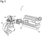
- FIG. 3 shows an example of an application in which a marine diesel engine 10 transmits its power to the drive shaft 11.
- the operating group unit 1 transmits power as required to the output shaft 13.
- a propeller 15 of a propeller group 12 is correspondingly driven via a transmission 14.
- Reference signs ⁇ /b> 1 Operating assembly 23 brake 2 Drive shaft unit 24 Output shaft 3 Output shaft unit 25th Working machine 4th Multi-disc clutch 28 Power take-off 5 Oil sump 29 Auxiliary unit 6th pump 30th Speed comparison 7th Holding brake 31 Pressure control 10 Marine diesel 11 drive shaft 12th Propeller assembly 13th Output shaft 14th transmission 15th propeller 20th Power machine 21 drive shaft 22nd coupling
Landscapes
- Engineering & Computer Science (AREA)
- General Engineering & Computer Science (AREA)
- Mechanical Engineering (AREA)
- Chemical & Material Sciences (AREA)
- Combustion & Propulsion (AREA)
- Ocean & Marine Engineering (AREA)
- Hydraulic Clutches, Magnetic Clutches, Fluid Clutches, And Fluid Joints (AREA)
- Braking Arrangements (AREA)
- Control Of Transmission Device (AREA)
Description
- Die vorliegende Erfindung betrifft eine Betriebsbaugruppe zur mechanischen Verbindung einer Kraftmaschine mit einer Arbeitsmaschine. Derartige Betriebsbaugruppen sind im Stand der Technik hinreichend bekannt. An einer Antriebswelleneinheit wird üblicherweise eine Kraftmaschine angeschlossen, an einer Abtriebswelleneinheit eine Arbeitsmaschine. Es ist bekannt, zwischen Antriebswelleneinheit und Abtriebswelleneinheit z. B. hydraulisch betätigte Lamellenkupplungen einzusetzen. Da es bekannt ist, dass unter Umständen Lamellenkupplungen je nach Gerätebetriebszustand auch unerwünschte Schleppmomente übertragen - dies ist insbesondere bei ölgeschmierten Lamellenkupplungen der Fall -, wird gegebenenfalls im Bereich einer Abtriebswelleneinheit oder Abtriebswelle eine Haltebremse eingesetzt, um die Arbeitsmaschine endgültig festzusetzen.
- Derartige Einheiten sind in unterschiedlichen Anwendungen im Einsatz, beispielsweise in maritimen Anwendungen zwischen Dieselaggregat und Propelleranlage, aber auch bei Stromgeneratoreinheiten und dergleichen. Ein Beispiel ist in das Dokument
DE10 2015 114926 A1 gezeigt. - Lamellenkupplungen sind ebenfalls an sich bekannte Baugruppen, bei welchen mit einer Antriebswelle direkt oder indirekt verbundene Lamellenscheiben gegenüber gehäuseseitig festgesetzten Lamellen rotieren. Diese Lamellenpakete sind entgegen Federkraft oder sonstige Vorspannung beispielweise mittels Hydraulikkraft in axialer Richtung bewegbar, so dass der Abstand zwischen den drehenden und den feststehenden Lamellen variierbar ist. Bei Vollkontakt erfolgt eine Leistungsübertragung (Drehzahl x Drehmoment), bei vollständiger Ablösung in einer ausreichenden Abstand bietenden Endposition sind Antrieb und Abtrieb voneinander getrennt. Zwischenstufen sind mit herkömmlichen Anlagen durch entsprechende Kontrolle des Druckmediums ansteuerbar.
- Sobald ein Antrieb startet und eine Antriebswelle rotieren lässt, wird die Antriebswelle der Kupplungseinheit in Rotation versetzt. Durch entsprechende Druckbeaufschlagung mittels Druckmedium z. B. Drucköl wird die Lamellenkupplung eingerückt und somit eine entsprechende Übertragung der Rotation ermöglicht.
- Es ist bekannt, dass alleine durch Druckvariation am Kupplungskolben eine im Wesentlichen stufenlose Drehzahlanpassung der Abtriebsseite gegenüber der Antriebsdrehzahl erfolgen kann, ohne selbst die Antriebsdrehzahl zu beeinflussen. Selbstredend sind Nebenaggregate zur Bereitstellung von Schmieröl, Kühlölmedium und dergleichen vorhanden.
- Es ist bekannt, dass diese Drehzahlanpassung in Bereichen niedriger Drehzahlen bei Verbrennungsmotoren eine Grenze hat. Üblicherweise sind Drehzahlen unterhalb der Motorleerlaufdrehzahlen nicht möglich. Mit Hilfe einer einstellbaren Lamellenkupplung besteht jedoch die Möglichkeit, diese mit geringem Betätigungsdruck zu betreiben, wobei man von einer "rutschenden Kupplung" spricht. In diesem Betriebszustand herrscht kein Synchronlauf zwischen An- und Abtriebsseite vor Dies erfolgt beispielsweise, wenn die Kraftmaschine aus anderen Gründen in einem entsprechend hohen Drehzahlbereich betrieben werden muss. Solche Gründe können die Leistungsbereitstellung für Sicherheitsvorrichtungen zur Feuerbekämpfung und dergleichen sein.
- Das Rutschen der Kupplungen erzeugt eine Verlustleistung.
- Der Kühlleistung kommt eine entsprechend große Bedeutung zu. Die entstehende Verlustleistung im Rutschbetrieb wird über die intern zugeführte Ölmenge aus der Kupplung abgeführt. Dieser Energieeintrag muss über einen Kühler aus dem System wieder abgeführt werden. Dies passiert üblicherweise über einen Wasser-Öl-Wärmetauscher. Neben der Menge des zugeführten Kühlmediums und der Eintrittstemperatur des Kühlmediums ist die kupplungsseitig zur Verfügung gestellte Ölmenge entsprechend entscheidend. Zur Dissipation hoher Verlustleistungen sind große Ölmengen erforderlich. Da im praktischen Betrieb der Einheiten allerdings nicht vorherbestimmbar ist, wann die maximale Verlustleistung auftreten wird, muss eine entsprechend große Kühlölmenge anstehen. Diese große Ölmenge führt jedoch bei geöffneter Kupplung dazu, dass hohe Schleppmomente entstehen, die auf der Abtriebsseite bereits zu entsprechend hohen Drehzahlen führen können. Diese Drehzahlen sind in der Regel aber bei offener Kupplung nicht erwünscht. Ziel wäre die stufenlose Drehzahleinstellung bis Null.
- Eine mögliche Abhilfe ist eine Haltebremse, mit welcher die Abtriebsseite endgültig festgesetzt wird. Es verbleibt aber ein unkontrollierbarer Drehzahlbereich.
- Ausgehend vom beschriebenen Stand der Technik liegt der vorliegenden Erfindung die AUFGABE zugrunde, eine Betriebsbaugruppe der gattungsgemäßen Art bereitzustellen, mit welcher größere Drehzahlbereiche insbesondere niedriger Drehzahlen eindeutig kontrollierbar sind. Darüber hinaus soll mit der Erfindung ein Verfahren zum Betrieb entsprechender Betriebsbaugruppen angegeben werden.
- Zur technischen LÖSUNG dieser Aufgabe wird eine Betriebsbaugruppe mit den Merkmalen des Patentanspruches 1 vorgeschlagen. Weitere Vorteile und Merkmale ergeben sich aus den Unteransprüchen.
- Ein Vorschlag für ein erfindungsgemäßes Verfahren ergibt sich aus den Merkmalen des Anspruches 7. Weitere Vorteile und Merkmale ergeben sich aus den Unteransprüchen.
- Erfindungsgemäß ist vorgesehen, eine dynamisch ansteuerbare Bremse als Haltebremse einzusetzen. Durch diese Maßnahme kann die Haltebremse dynamisch angesteuert werden und es kann ein bedarfsgerechtes Bremsmoment eingestellt werden.
- Sowohl die Kupplungen als auch die Bremsen können mit unterschiedlichen Medien betätigt werden. Generell spricht man von Hilfsenergie. Wenn im Rahmen der vorliegenden Anmeldung beispielhaft von Hydraulik, Steuerung des Hydraulikdruckes, hydraulischer Kupplung, hydraulischer Bremse und dergleichen gesprochen wird, so ist dies nicht beschränkend. Umfasst sind auch alle anderen möglichen Hilfsenergien, mit welchen entsprechende Kupplungen und Bremsen betätigbar sind.
- Insofern können durch gleichzeitige Kontrolle des Hydraulikdruckes an der Lamellenkupplung einerseits und des Hydraulikdruckes an der Haltebremse andererseits Schleppmomente in der Lamellenkupplung kompensiert werden.
- Durch die erfindungsgemäße Betriebsbaugruppe ist es möglich, die Abtriebsdrehzahl nahezu zwischen 0 und 100 % der Antriebsdrehzahl einzuregeln und zu kontrollieren.
- Gemäß einem vorteilhaften Vorschlag der Erfindung können die Lamellenkupplung und die Haltebremse in einem Gehäuse integriert sein. Durch diesen Vorschlag kann eine besonders kompakte Einheit erstellt werden, die in einer Wellenleitung, die unter anderem Gelenkwellen aufweisen kann, einsetzbar ist. Eine entsprechende Betriebsbaugruppe kann Nebenantriebe aufweisen, die gemäß einem weiteren Vorschlag der Erfindung für eine Hydraulikversorgung der erforderlichen Leistungsströme, Schmiermittelströme und/oder Kühlölströme einsetzbar sind. Derartige Nebenantriebe können beispielsweise mit der Antriebswelleneinheit verbunden sein.
- Gemäß der Erfindung weist die Betriebsbaugruppe eine Steuereinheit auf. Diese ist so ausgelegt, dass sie eine Einheit zur stufenlosen Regelung des Hydraulikdruckes an der Lamellenkupplung umfasst, so dass die Lamellenkupplung zwischen voller Leistungsübertragung einerseits und vollständiger Trennung andererseits einstellbar ist. Weiterhin umfasst die Steuereinheit eine Einheit zur Einstellung des Hydraulikdruckes an der Haltebremse, so dass diese zwischen Freilauf und Fixierung einstellbar ist.
- Durch die erfindungsgemäße Lösung wird eine Betriebsbaugruppe bereitgestellt, die in einfacher Weise aufbaubar und einsetzbar ist. Gemäß einem vorteilhaften Vorschlag der Erfindung wird diese beispielsweise für einen Marinepropulsionsantrieb zwischen Dieselmaschine und Propeller eingesetzt. Die Verwendung der erfindungsgemäßen Vorrichtung kann durch Druckvariation am Bremskolben das Schleppmoment von der Kupplung soweit kompensieren, dass die Abtriebsdrehzahl auf den vom Betreiber gewünschten Wert eingestellt werden kann. Ist das Schleppmoment zu gering, wird die Bremse komplett geöffnet und die schlupfende Kupplung kann die Abtriebsdrehzahl wie gewohnt auf den gewünschten Wert anheben. Die Drehzahlregelung erfolgt über den Drehzahlabgleich zwischen An- und Abtriebsdrehzahl und der damit verbundenen Druckanpassung mittels beispielsweise Proportionalventilen. Mit der Erfindung ist es auch möglich, die Bremse mit einem festen Druck zu beaufschlagen, und zwar im Bereich langsamer Abtriebsdrehzahlen, welcher so hoch ist, dass das maximal auftretende Schleppmoment komplett kompensiert wird. Bei Ausfall der Druckerzeugung kann die Haltebremse mittels Vorrichtung manuell eingerückt werden.
- Verfahrensseitig wird mit der Erfindung vorgeschlagen, sowohl den Druck an der Lamellenkupplung als auch den Druck an der Haltebremse einzustellen bzw. zu regeln. Hierzu ist der Einsatz einer ansteuerbaren hydraulischen Bremse erforderlich, wie dies von der Erfindung vorgeschlagen wird. Auf diese Weise kann erfindungsgemäß ein an der Lamellenkupplung auftretendes Schleppmoment durch die Regelung des an der Haltebremse anliegenden Hydraulikdruckes kontrolliert werden. Die Regelung ermöglicht also eine Abtriebsdrehzahl völlig unabhängig von der Drehzahl der Kraftmaschine vorzunehmen. Dabei ist natürlich selbstverständlich, dass die Kraftmaschine eine entsprechend höhere Drehzahl bereitstellt.
- Erfindungsgemäß ist vorgesehen, dass die Kraftmaschine mi einer Mindestdrehzahl betrieben wird. Auf diese Weise können Notfunktionen versorgt werden, beispielsweise der Notbetrieb von Sicherheitsanlagen, oder auch Betriebszustände beispielsweise eines Schiffes, unter anderem Position im Gegenstrom halten, Langsamfahrt im Hafenbereich, Feuerlöschpumpen betreiben und den Rückstoß ausgleichen und dergleichen.
- Gemäß der Erfindung werden also Kupplung und Bremse beide angesteuert. Dies setzt voraus, dass erfindungsgemäß eine dynamisch ansteuerbare Bremse eingesetzt wird. Die Vorrichtung umfasst also eine Kupplung und eine Bremse, die beide dynamisch derart ansteuerbar sind, dass selbst bei niedrigen Drehzahlen eine kontrollierbare Abtriebsdrehzahl eingestellt und aufrecht erhalten werden kann.
- Weitere Vorteile und Merkmale der Erfindung ergeben sich aus der folgenden Beschreibung anhand der Figuren. Dabei zeigen:
- Fig. 1
- eine geschnittene Prinzipdarstellung einer erfindungsgemäßen Betriebsbaugruppe;
- Fig.2
- eine schematische Darstellung der Funktionsgruppen und der Regelungsvorgänge und
- Fig. 3
- eine perspektivische Darstellung einer Anwendung einer erfindungsgemäßen Betriebsbaugruppe in einem Marinepropulsionsantrieb.
- In den Figuren sind gleiche Elemente mit gleichen Bezugszeichen versehen.
- Wie in
Figur 1 gezeigt ist, besteht das Ausführungsbeispiel aus einer integrierten Baugruppe, bei welcher eine Antriebswelleneinheit 2 über eine Lamellenkupplung 4 und einer Haltebremse 7 auf einer Abtriebsweileneinheit 3 durchgeführt ist. Hydrauliköl wird aus einem Ölsumpf 5 bereitgestellt, der beispielsweise über eine angeschlossene Pumpe 6 gefördert wird. - Bei der Haltebremse 7 handelt es sich ebenso wie bei der Lamellenkupplung 4 um eine dynamisch ansteuerbare Baugruppe.
- Gemäß
Figur 2 wird die Drehzahl einer Antriebswelle 21, die von einer Kraftmaschine 20 angetrieben wird und einer Abtriebswelle 24, die auf einer Arbeitsmaschine 25 überträgt, verglichen. Je nach Sollvorgabe sorgt die Steuereinheit (nicht gezeigt) dafür, dass ein entsprechendes Drehmoment eingestellt wird, was mit 31 angedeutet ist. Es erfolgt also eine entsprechende Druckzuführung auf die Lamellenkupplung 22 einerseits und unabhängig davon auf die Haltebremse 23, wenn hierfür Bedarf besteht. -
Figur 3 zeigt beispielhaft einen Einsatzfall, wobei ein Schiffsdiesel 10 seine Leistung auf die Antriebswelle 11 gibt. Die Betriebsgruppeneinheit 1 übertragt Leistung bedarfsgerecht auf die Abtriebswelle 13. Über ein Getriebe 14 wird ein Propeller 15 einer Propellergruppe 12 entsprechend angetrieben.Bezugszeichen 1 Betriebsbaugruppe 23 Bremse 2 Antriebswelleneinheit 24 Abtriebswelle 3 Abtriebswelleneinheit 25 Arbeitsmaschine 4 Lamellenkupplung 28 Nebenantrieb 5 Ölsumpf 29 Nebenaggregat 6 Pumpe 30 Drehzahlvergleich 7 Haltebremse 31 Drucksteuerung 10 Schiffsdiesel 11 Antriebswelle 12 Propellerbaugruppe 13 Abtriebswelle 14 Getriebe 15 Propeller 20 Kraftmaschine 21 Antriebswelle 22 Kupplung
Claims (10)
- Betriebsbaugruppe zur mechanischen Verbindung einer Kraftmaschine (20) mit einer Arbeitsmaschine (25), mit einer Antriebswelleneinheit (2) und einer Abtriebswelleneinheit (3), welche mittels einer dynamisch ansteuerbaren Lamellenkupplung (4) verbunden sind, wobei die Lamellenkupplung (4) in einem Betriebszustand betreibbar ist, in dem zwischen An- und Abtriebsseite kein Synchronlauf vorherrscht, und mit einer auf die Abtriebswelleneinheit (3) wirkenden Haltebremse (7) sowie einer Steuereinheit, dadurch gekennzeichnet, dass die Haltebremse (7) eine dynamisch ansteuerbare Bremse ist.
- Betriebsbaugruppe nach Anspruch 1, dadurch gekennzeichnet, dass die Lamellenkupplung (4) und die Haltebremse (7) in einem gemeinsamen Gehäuse integriert sind.
- Betriebsbaugruppe nach einem der vorhergehenden Ansprüche, dadurch gekennzeichnet, dass diese Nebenantriebe (28) aufweist.
- Betriebsbaugruppe nach Anspruch 3, dadurch gekennzeichnet, dass über die Nebenantriebe (28) Pumpen für eine Hydraulikversorgung der erforderlichen Leistungs-, Schmier- und/oder Kühlölströme antreibbar sind.
- Betriebsbaugruppe nach einem der vorhergehenden Ansprüche, dadurch gekennzeichnet, dass diese eine elektrisch betriebene Pumpe aufweist.
- Betriebsbaugruppe nach einem der vorhergehenden Ansprüche, dadurch gekennzeichnet, dass die Steuereinheit eine Einheit zur stufenlosen Regelung des Hydraulikdruckes an der Lamellenkupplung (4) zwischen Trennung und voller Leistungsübertragung sowie eine Einheit zur stufenlosen Einstellung des Hydraulikdruckes an der Haltebremse (7) zwischen Freilauf und Fixierung umfasst.
- Verfahren zum Betrieb einer Betriebsbaugruppe nach wenigstens einem der Ansprüche 1 bis 6, dadurch gekennzeichnet, dass die Abtriebsdrehzahl durch eine Ansteuerung sowohl der Lamellenkupplung (4) als auch der Haltebremse (7) geregelt wird.
- Verfahren nach Anspruch 7, dadurch gekennzeichnet, dass an der Lamellenkupplung (4) auftretende Schleppmomente durch Ansteuerung der Haltebremse (7) kompensiert werden.
- Verfahren nach einem der vorhergehenden Ansprüche 7 oder 8, dadurch gekennzeichnet, dass die Regelung der Abtriebsdrehzahl unabhängig von der Drehzahl der Kraftmaschine (20) erfolgt.
- Verfahren nach einem der vorhergehenden Ansprüche 7 bis 9, dadurch gekennzeichnet, dass die Regelung unter Aufrechterhaltung einer Mindestdrehzahl der Kraftmaschine (20) erfolgt.
Priority Applications (4)
| Application Number | Priority Date | Filing Date | Title |
|---|---|---|---|
| EP16166127.7A EP3236101B1 (de) | 2016-04-20 | 2016-04-20 | Kupplungsbaugruppe |
| CN201610346518.XA CN105864314B (zh) | 2016-04-20 | 2016-05-23 | 离合器组件 |
| US15/172,521 US10352386B2 (en) | 2016-04-20 | 2016-06-03 | Clutch assembly |
| JP2017074228A JP7144128B2 (ja) | 2016-04-20 | 2017-04-04 | クラッチアセンブリ |
Applications Claiming Priority (1)
| Application Number | Priority Date | Filing Date | Title |
|---|---|---|---|
| EP16166127.7A EP3236101B1 (de) | 2016-04-20 | 2016-04-20 | Kupplungsbaugruppe |
Publications (2)
| Publication Number | Publication Date |
|---|---|
| EP3236101A1 EP3236101A1 (de) | 2017-10-25 |
| EP3236101B1 true EP3236101B1 (de) | 2021-03-17 |
Family
ID=55970771
Family Applications (1)
| Application Number | Title | Priority Date | Filing Date |
|---|---|---|---|
| EP16166127.7A Active EP3236101B1 (de) | 2016-04-20 | 2016-04-20 | Kupplungsbaugruppe |
Country Status (4)
| Country | Link |
|---|---|
| US (1) | US10352386B2 (de) |
| EP (1) | EP3236101B1 (de) |
| JP (1) | JP7144128B2 (de) |
| CN (1) | CN105864314B (de) |
Families Citing this family (2)
| Publication number | Priority date | Publication date | Assignee | Title |
|---|---|---|---|---|
| US20180252272A1 (en) * | 2017-03-06 | 2018-09-06 | Wpt Power Corporation | Power takeoff unit with actuation and lubrication fluid channels |
| EP3592643B1 (de) | 2017-03-10 | 2023-06-14 | ZF Friedrichshafen AG | Segelantriebsanordnung |
Family Cites Families (25)
| Publication number | Priority date | Publication date | Assignee | Title |
|---|---|---|---|---|
| US2658412A (en) * | 1948-04-13 | 1953-11-10 | Borg Warner | Transmission |
| GB665743A (en) * | 1948-10-29 | 1952-01-30 | Albert Doebeli | Improvements in and relating to electro-magnetically actuated friction couplings with servo-action, more particularly for power driven vehicles |
| US2786560A (en) * | 1953-08-07 | 1957-03-26 | Lambert & Brake Corp | Clutch and brake combination for power transmission systems of farm tractors and thelike |
| US4074581A (en) * | 1976-05-11 | 1978-02-21 | Caterpillar Tractor Co. | Compact transmission having a power takeoff shaft and hydraulically actuated clutches |
| JPS5786643A (en) * | 1980-11-17 | 1982-05-29 | Komatsu Ltd | Clutch brake for vehicle |
| EP0200335B1 (de) * | 1985-04-03 | 1989-11-15 | Eaton Corporation | Strömungswandler mit Kupplungsanordnung zum Überbrücken und Unterbrechen für automatische mechanische Getriebe |
| US4828089A (en) * | 1985-05-07 | 1989-05-09 | Eaton Corporation | Brake/clutch with direct liquid cooling |
| JP2503709B2 (ja) * | 1990-02-26 | 1996-06-05 | 株式会社豊田自動織機製作所 | 産業車両におけるインチング制御装置 |
| JP2590343Y2 (ja) * | 1991-03-06 | 1999-02-10 | 株式会社 神崎高級工機製作所 | 舶用推進装置 |
| JPH06144377A (ja) * | 1991-11-15 | 1994-05-24 | Yanmar Diesel Engine Co Ltd | 減速逆転機の中立ブレーキ解除装置 |
| US5190129A (en) * | 1992-01-24 | 1993-03-02 | Midwest Brake Bond Co. | Press drive with oil shear clutch/brake drives |
| US5291977A (en) * | 1992-07-27 | 1994-03-08 | Midwest Brake Bond Co. | Electrically actuated clutch brake apparatus |
| US5487456A (en) * | 1994-07-07 | 1996-01-30 | Sommer Company | Press drive with oil shear clutch/brake drives with internal flywheel brake |
| JP2004042801A (ja) * | 2002-07-12 | 2004-02-12 | Komatsu Forklift Co Ltd | 産業車両の走行制御装置 |
| CN1884866A (zh) * | 2006-06-30 | 2006-12-27 | 刘建平 | 机动车柔性可控离合装置 |
| DE102008009516A1 (de) * | 2008-02-15 | 2009-08-20 | Herion Systemtechnik Gmbh | Kupplungs-Bremskombination |
| JP2009202732A (ja) * | 2008-02-27 | 2009-09-10 | Yamaha Motor Co Ltd | 船舶用推進システム |
| ES2310497B1 (es) * | 2008-07-08 | 2009-10-27 | Goizper, S.Coop | Dispositivo de freno y embrague combinado para prensas. |
| US9194473B1 (en) * | 2009-06-26 | 2015-11-24 | Hydro-Gear Limited Partnership | Modular power distribution and drive system |
| US8393236B1 (en) * | 2009-06-26 | 2013-03-12 | Hydro-Gear Limited Partnership | Modular power distribution and drive system |
| CN201902488U (zh) * | 2010-12-31 | 2011-07-20 | 周云飞 | 一种带离合器的车辆缓速装置 |
| US9221336B1 (en) * | 2011-11-14 | 2015-12-29 | Hydro-Gear Limited Partnership | Integral power distribution assembly for engine |
| JP6110603B2 (ja) * | 2012-04-24 | 2017-04-05 | 富士重工業株式会社 | 車両 |
| DE102015114926B4 (de) * | 2015-09-07 | 2020-01-23 | Desch Antriebstechnik Gmbh & Co. Kg | Verwendung einer Kupplungs- und Bremsvorrichtung für eine Bearbeitungsmaschine |
| PL3416847T3 (pl) * | 2016-02-18 | 2024-01-22 | Twin Disc, Inc. | Hydrauliczna przystawka odbioru mocy z układem rozłączania hamulca do napędów przemysłowych |
-
2016
- 2016-04-20 EP EP16166127.7A patent/EP3236101B1/de active Active
- 2016-05-23 CN CN201610346518.XA patent/CN105864314B/zh active Active
- 2016-06-03 US US15/172,521 patent/US10352386B2/en active Active
-
2017
- 2017-04-04 JP JP2017074228A patent/JP7144128B2/ja active Active
Non-Patent Citations (1)
| Title |
|---|
| None * |
Also Published As
| Publication number | Publication date |
|---|---|
| US20170307037A1 (en) | 2017-10-26 |
| CN105864314B (zh) | 2021-05-04 |
| US10352386B2 (en) | 2019-07-16 |
| EP3236101A1 (de) | 2017-10-25 |
| CN105864314A (zh) | 2016-08-17 |
| JP7144128B2 (ja) | 2022-09-29 |
| JP2017194155A (ja) | 2017-10-26 |
Similar Documents
| Publication | Publication Date | Title |
|---|---|---|
| EP3774424B1 (de) | Hybridantriebsmodul für ein kraftfahrzeug | |
| DE102016118686B4 (de) | Hydraulik-steuerungskreislauf für einen hydraulischen drehmomentwandler | |
| EP2841203B1 (de) | Antriebseinrichtung und arbeitsmaschineneinrichtung | |
| EP1550820A3 (de) | Kraftfahrzeug mit einem eine Mehrfach-Kupplungseinrichtung aufweisenden Antriebsstrang | |
| DE102007050802B4 (de) | Elektrohydraulische Getriebesteuerung, Getriebeeinrichtung und Fahrzeugantriebsstrang | |
| DE10314338A1 (de) | Hydrodynamischer Wandler mit Primär- und Wandlerüberbrückungskupplung | |
| DE102011077552A1 (de) | Hydraulikanordnung für ein Getriebe | |
| DE112016001216T5 (de) | Verdrängungspumpenanordnung für antriebsstrangsysteme und hydrauliksteuersystem, das diese einbezieht | |
| DE112009004351B4 (de) | Bremsschmiervorrichtung und Verfahren zu deren Steuerung | |
| DE102017207569B4 (de) | Hydrostatisches Getriebe und Verfahren zur Bremsung damit | |
| DE102018214427A1 (de) | Hydrauliksystem für ein Doppelkupplungsgetriebe | |
| DE102017103648B4 (de) | Hydraulisches steuersystem | |
| DE102017202273B4 (de) | Hydrostatisches Getriebe und Verfahren zur Bremsung damit | |
| EP3236101A1 (de) | Kupplungsbaugruppe | |
| DE102014118446B4 (de) | Kreislauf zum Steuern von Hydraulikdruck eines Drehmomentwandlers | |
| EP2500100B1 (de) | Antriebseinrichtung und Arbeitsmaschineneinrichtung | |
| DE102006022334A1 (de) | Trockenreibungs-Anfahrkupplung für ein Automatikgetriebe und Verfahren dafür | |
| DE10150598A1 (de) | Kupplungssystem mit wenigstens einer druckmittelbetätigbaren, für einen Betrieb unter Einwirkung eines Betriebsmediums vorgesehenen Kupplungsanordnung | |
| DE1625049A1 (de) | Getriebe | |
| DE102016106163A1 (de) | Getriebe mit einer kupplungsnabe für hohe drehzahlen | |
| DE2407288A1 (de) | Verfahren zum verringern der fluessigkeitsreibung in einem mit einem oelbad versehenen triebwerk, insbesondere einer reibungskupplung, und einrichtung zum ausfuehren dieses verfahrens | |
| DE102020205395A1 (de) | Verfahren zum Betrieb eines Kraftfahrzeug Antriebsstranges, sowie elektronische Steuereinheit zur Durchführung des Verfahrens | |
| DE102015207851A1 (de) | Steuerungsverfahren und damit betriebener hydrodynamischer Retarder | |
| DE102004031484B4 (de) | Hydraulisches System | |
| DE102010063084B3 (de) | Antriebsstrang eines Hydraulikantriebs mit einer Kupplung |
Legal Events
| Date | Code | Title | Description |
|---|---|---|---|
| PUAI | Public reference made under article 153(3) epc to a published international application that has entered the european phase |
Free format text: ORIGINAL CODE: 0009012 |
|
| STAA | Information on the status of an ep patent application or granted ep patent |
Free format text: STATUS: THE APPLICATION HAS BEEN PUBLISHED |
|
| AK | Designated contracting states |
Kind code of ref document: A1 Designated state(s): AL AT BE BG CH CY CZ DE DK EE ES FI FR GB GR HR HU IE IS IT LI LT LU LV MC MK MT NL NO PL PT RO RS SE SI SK SM TR |
|
| AX | Request for extension of the european patent |
Extension state: BA ME |
|
| STAA | Information on the status of an ep patent application or granted ep patent |
Free format text: STATUS: REQUEST FOR EXAMINATION WAS MADE |
|
| 17P | Request for examination filed |
Effective date: 20180425 |
|
| RBV | Designated contracting states (corrected) |
Designated state(s): AL AT BE BG CH CY CZ DE DK EE ES FI FR GB GR HR HU IE IS IT LI LT LU LV MC MK MT NL NO PL PT RO RS SE SI SK SM TR |
|
| GRAP | Despatch of communication of intention to grant a patent |
Free format text: ORIGINAL CODE: EPIDOSNIGR1 |
|
| STAA | Information on the status of an ep patent application or granted ep patent |
Free format text: STATUS: GRANT OF PATENT IS INTENDED |
|
| INTG | Intention to grant announced |
Effective date: 20201111 |
|
| GRAS | Grant fee paid |
Free format text: ORIGINAL CODE: EPIDOSNIGR3 |
|
| GRAA | (expected) grant |
Free format text: ORIGINAL CODE: 0009210 |
|
| STAA | Information on the status of an ep patent application or granted ep patent |
Free format text: STATUS: THE PATENT HAS BEEN GRANTED |
|
| AK | Designated contracting states |
Kind code of ref document: B1 Designated state(s): AL AT BE BG CH CY CZ DE DK EE ES FI FR GB GR HR HU IE IS IT LI LT LU LV MC MK MT NL NO PL PT RO RS SE SI SK SM TR |
|
| REG | Reference to a national code |
Ref country code: GB Ref legal event code: FG4D Free format text: NOT ENGLISH |
|
| REG | Reference to a national code |
Ref country code: CH Ref legal event code: EP |
|
| REG | Reference to a national code |
Ref country code: DE Ref legal event code: R096 Ref document number: 502016012587 Country of ref document: DE |
|
| REG | Reference to a national code |
Ref country code: IE Ref legal event code: FG4D Free format text: LANGUAGE OF EP DOCUMENT: GERMAN |
|
| REG | Reference to a national code |
Ref country code: AT Ref legal event code: REF Ref document number: 1372522 Country of ref document: AT Kind code of ref document: T Effective date: 20210415 |
|
| REG | Reference to a national code |
Ref country code: LT Ref legal event code: MG9D |
|
| PG25 | Lapsed in a contracting state [announced via postgrant information from national office to epo] |
Ref country code: BG Free format text: LAPSE BECAUSE OF FAILURE TO SUBMIT A TRANSLATION OF THE DESCRIPTION OR TO PAY THE FEE WITHIN THE PRESCRIBED TIME-LIMIT Effective date: 20210617 Ref country code: FI Free format text: LAPSE BECAUSE OF FAILURE TO SUBMIT A TRANSLATION OF THE DESCRIPTION OR TO PAY THE FEE WITHIN THE PRESCRIBED TIME-LIMIT Effective date: 20210317 Ref country code: GR Free format text: LAPSE BECAUSE OF FAILURE TO SUBMIT A TRANSLATION OF THE DESCRIPTION OR TO PAY THE FEE WITHIN THE PRESCRIBED TIME-LIMIT Effective date: 20210618 Ref country code: HR Free format text: LAPSE BECAUSE OF FAILURE TO SUBMIT A TRANSLATION OF THE DESCRIPTION OR TO PAY THE FEE WITHIN THE PRESCRIBED TIME-LIMIT Effective date: 20210317 Ref country code: NO Free format text: LAPSE BECAUSE OF FAILURE TO SUBMIT A TRANSLATION OF THE DESCRIPTION OR TO PAY THE FEE WITHIN THE PRESCRIBED TIME-LIMIT Effective date: 20210617 |
|
| REG | Reference to a national code |
Ref country code: NL Ref legal event code: MP Effective date: 20210317 |
|
| PG25 | Lapsed in a contracting state [announced via postgrant information from national office to epo] |
Ref country code: RS Free format text: LAPSE BECAUSE OF FAILURE TO SUBMIT A TRANSLATION OF THE DESCRIPTION OR TO PAY THE FEE WITHIN THE PRESCRIBED TIME-LIMIT Effective date: 20210317 Ref country code: LV Free format text: LAPSE BECAUSE OF FAILURE TO SUBMIT A TRANSLATION OF THE DESCRIPTION OR TO PAY THE FEE WITHIN THE PRESCRIBED TIME-LIMIT Effective date: 20210317 Ref country code: SE Free format text: LAPSE BECAUSE OF FAILURE TO SUBMIT A TRANSLATION OF THE DESCRIPTION OR TO PAY THE FEE WITHIN THE PRESCRIBED TIME-LIMIT Effective date: 20210317 |
|
| PG25 | Lapsed in a contracting state [announced via postgrant information from national office to epo] |
Ref country code: NL Free format text: LAPSE BECAUSE OF FAILURE TO SUBMIT A TRANSLATION OF THE DESCRIPTION OR TO PAY THE FEE WITHIN THE PRESCRIBED TIME-LIMIT Effective date: 20210317 |
|
| PG25 | Lapsed in a contracting state [announced via postgrant information from national office to epo] |
Ref country code: LT Free format text: LAPSE BECAUSE OF FAILURE TO SUBMIT A TRANSLATION OF THE DESCRIPTION OR TO PAY THE FEE WITHIN THE PRESCRIBED TIME-LIMIT Effective date: 20210317 Ref country code: EE Free format text: LAPSE BECAUSE OF FAILURE TO SUBMIT A TRANSLATION OF THE DESCRIPTION OR TO PAY THE FEE WITHIN THE PRESCRIBED TIME-LIMIT Effective date: 20210317 Ref country code: CZ Free format text: LAPSE BECAUSE OF FAILURE TO SUBMIT A TRANSLATION OF THE DESCRIPTION OR TO PAY THE FEE WITHIN THE PRESCRIBED TIME-LIMIT Effective date: 20210317 Ref country code: SM Free format text: LAPSE BECAUSE OF FAILURE TO SUBMIT A TRANSLATION OF THE DESCRIPTION OR TO PAY THE FEE WITHIN THE PRESCRIBED TIME-LIMIT Effective date: 20210317 |
|
| PG25 | Lapsed in a contracting state [announced via postgrant information from national office to epo] |
Ref country code: IS Free format text: LAPSE BECAUSE OF FAILURE TO SUBMIT A TRANSLATION OF THE DESCRIPTION OR TO PAY THE FEE WITHIN THE PRESCRIBED TIME-LIMIT Effective date: 20210717 Ref country code: PL Free format text: LAPSE BECAUSE OF FAILURE TO SUBMIT A TRANSLATION OF THE DESCRIPTION OR TO PAY THE FEE WITHIN THE PRESCRIBED TIME-LIMIT Effective date: 20210317 Ref country code: PT Free format text: LAPSE BECAUSE OF FAILURE TO SUBMIT A TRANSLATION OF THE DESCRIPTION OR TO PAY THE FEE WITHIN THE PRESCRIBED TIME-LIMIT Effective date: 20210719 Ref country code: SK Free format text: LAPSE BECAUSE OF FAILURE TO SUBMIT A TRANSLATION OF THE DESCRIPTION OR TO PAY THE FEE WITHIN THE PRESCRIBED TIME-LIMIT Effective date: 20210317 Ref country code: RO Free format text: LAPSE BECAUSE OF FAILURE TO SUBMIT A TRANSLATION OF THE DESCRIPTION OR TO PAY THE FEE WITHIN THE PRESCRIBED TIME-LIMIT Effective date: 20210317 |
|
| REG | Reference to a national code |
Ref country code: DE Ref legal event code: R097 Ref document number: 502016012587 Country of ref document: DE |
|
| PG25 | Lapsed in a contracting state [announced via postgrant information from national office to epo] |
Ref country code: LU Free format text: LAPSE BECAUSE OF NON-PAYMENT OF DUE FEES Effective date: 20210420 |
|
| REG | Reference to a national code |
Ref country code: BE Ref legal event code: MM Effective date: 20210430 |
|
| PLBE | No opposition filed within time limit |
Free format text: ORIGINAL CODE: 0009261 |
|
| STAA | Information on the status of an ep patent application or granted ep patent |
Free format text: STATUS: NO OPPOSITION FILED WITHIN TIME LIMIT |
|
| PG25 | Lapsed in a contracting state [announced via postgrant information from national office to epo] |
Ref country code: DK Free format text: LAPSE BECAUSE OF FAILURE TO SUBMIT A TRANSLATION OF THE DESCRIPTION OR TO PAY THE FEE WITHIN THE PRESCRIBED TIME-LIMIT Effective date: 20210317 Ref country code: MC Free format text: LAPSE BECAUSE OF FAILURE TO SUBMIT A TRANSLATION OF THE DESCRIPTION OR TO PAY THE FEE WITHIN THE PRESCRIBED TIME-LIMIT Effective date: 20210317 Ref country code: LI Free format text: LAPSE BECAUSE OF NON-PAYMENT OF DUE FEES Effective date: 20210430 Ref country code: AL Free format text: LAPSE BECAUSE OF FAILURE TO SUBMIT A TRANSLATION OF THE DESCRIPTION OR TO PAY THE FEE WITHIN THE PRESCRIBED TIME-LIMIT Effective date: 20210317 Ref country code: CH Free format text: LAPSE BECAUSE OF NON-PAYMENT OF DUE FEES Effective date: 20210430 Ref country code: ES Free format text: LAPSE BECAUSE OF FAILURE TO SUBMIT A TRANSLATION OF THE DESCRIPTION OR TO PAY THE FEE WITHIN THE PRESCRIBED TIME-LIMIT Effective date: 20210317 |
|
| 26N | No opposition filed |
Effective date: 20211220 |
|
| GBPC | Gb: european patent ceased through non-payment of renewal fee |
Effective date: 20210617 |
|
| PG25 | Lapsed in a contracting state [announced via postgrant information from national office to epo] |
Ref country code: SI Free format text: LAPSE BECAUSE OF FAILURE TO SUBMIT A TRANSLATION OF THE DESCRIPTION OR TO PAY THE FEE WITHIN THE PRESCRIBED TIME-LIMIT Effective date: 20210317 |
|
| PG25 | Lapsed in a contracting state [announced via postgrant information from national office to epo] |
Ref country code: IE Free format text: LAPSE BECAUSE OF NON-PAYMENT OF DUE FEES Effective date: 20210420 Ref country code: GB Free format text: LAPSE BECAUSE OF NON-PAYMENT OF DUE FEES Effective date: 20210617 |
|
| PG25 | Lapsed in a contracting state [announced via postgrant information from national office to epo] |
Ref country code: IS Free format text: LAPSE BECAUSE OF FAILURE TO SUBMIT A TRANSLATION OF THE DESCRIPTION OR TO PAY THE FEE WITHIN THE PRESCRIBED TIME-LIMIT Effective date: 20210717 |
|
| REG | Reference to a national code |
Ref country code: AT Ref legal event code: MM01 Ref document number: 1372522 Country of ref document: AT Kind code of ref document: T Effective date: 20210420 |
|
| PG25 | Lapsed in a contracting state [announced via postgrant information from national office to epo] |
Ref country code: BE Free format text: LAPSE BECAUSE OF NON-PAYMENT OF DUE FEES Effective date: 20210430 |
|
| PG25 | Lapsed in a contracting state [announced via postgrant information from national office to epo] |
Ref country code: AT Free format text: LAPSE BECAUSE OF NON-PAYMENT OF DUE FEES Effective date: 20210420 |
|
| PG25 | Lapsed in a contracting state [announced via postgrant information from national office to epo] |
Ref country code: HU Free format text: LAPSE BECAUSE OF FAILURE TO SUBMIT A TRANSLATION OF THE DESCRIPTION OR TO PAY THE FEE WITHIN THE PRESCRIBED TIME-LIMIT; INVALID AB INITIO Effective date: 20160420 |
|
| P01 | Opt-out of the competence of the unified patent court (upc) registered |
Effective date: 20230522 |
|
| PG25 | Lapsed in a contracting state [announced via postgrant information from national office to epo] |
Ref country code: CY Free format text: LAPSE BECAUSE OF FAILURE TO SUBMIT A TRANSLATION OF THE DESCRIPTION OR TO PAY THE FEE WITHIN THE PRESCRIBED TIME-LIMIT Effective date: 20210317 |
|
| PG25 | Lapsed in a contracting state [announced via postgrant information from national office to epo] |
Ref country code: MK Free format text: LAPSE BECAUSE OF FAILURE TO SUBMIT A TRANSLATION OF THE DESCRIPTION OR TO PAY THE FEE WITHIN THE PRESCRIBED TIME-LIMIT Effective date: 20210317 |
|
| PG25 | Lapsed in a contracting state [announced via postgrant information from national office to epo] |
Ref country code: TR Free format text: LAPSE BECAUSE OF FAILURE TO SUBMIT A TRANSLATION OF THE DESCRIPTION OR TO PAY THE FEE WITHIN THE PRESCRIBED TIME-LIMIT Effective date: 20210317 |
|
| PG25 | Lapsed in a contracting state [announced via postgrant information from national office to epo] |
Ref country code: MT Free format text: LAPSE BECAUSE OF FAILURE TO SUBMIT A TRANSLATION OF THE DESCRIPTION OR TO PAY THE FEE WITHIN THE PRESCRIBED TIME-LIMIT Effective date: 20210317 |
|
| PGFP | Annual fee paid to national office [announced via postgrant information from national office to epo] |
Ref country code: DE Payment date: 20250623 Year of fee payment: 10 |
|
| PGFP | Annual fee paid to national office [announced via postgrant information from national office to epo] |
Ref country code: IT Payment date: 20250424 Year of fee payment: 10 |
|
| PGFP | Annual fee paid to national office [announced via postgrant information from national office to epo] |
Ref country code: FR Payment date: 20250425 Year of fee payment: 10 |