EP3236028B1 - Variable valve mechanism of internal combustion engine - Google Patents
Variable valve mechanism of internal combustion engine Download PDFInfo
- Publication number
- EP3236028B1 EP3236028B1 EP16197491.0A EP16197491A EP3236028B1 EP 3236028 B1 EP3236028 B1 EP 3236028B1 EP 16197491 A EP16197491 A EP 16197491A EP 3236028 B1 EP3236028 B1 EP 3236028B1
- Authority
- EP
- European Patent Office
- Prior art keywords
- variable
- variable device
- valve
- control shaft
- valve mechanism
- Prior art date
- Legal status (The legal status is an assumption and is not a legal conclusion. Google has not performed a legal analysis and makes no representation as to the accuracy of the status listed.)
- Not-in-force
Links
- 230000007246 mechanism Effects 0.000 title claims description 59
- 238000002485 combustion reaction Methods 0.000 title claims description 15
- 230000005540 biological transmission Effects 0.000 claims description 14
- 238000010586 diagram Methods 0.000 description 10
- 230000003247 decreasing effect Effects 0.000 description 9
- 230000000694 effects Effects 0.000 description 3
Images


Classifications
-
- F—MECHANICAL ENGINEERING; LIGHTING; HEATING; WEAPONS; BLASTING
- F01—MACHINES OR ENGINES IN GENERAL; ENGINE PLANTS IN GENERAL; STEAM ENGINES
- F01L—CYCLICALLY OPERATING VALVES FOR MACHINES OR ENGINES
- F01L1/00—Valve-gear or valve arrangements, e.g. lift-valve gear
- F01L1/20—Adjusting or compensating clearance
- F01L1/22—Adjusting or compensating clearance automatically, e.g. mechanically
-
- F—MECHANICAL ENGINEERING; LIGHTING; HEATING; WEAPONS; BLASTING
- F01—MACHINES OR ENGINES IN GENERAL; ENGINE PLANTS IN GENERAL; STEAM ENGINES
- F01L—CYCLICALLY OPERATING VALVES FOR MACHINES OR ENGINES
- F01L1/00—Valve-gear or valve arrangements, e.g. lift-valve gear
- F01L1/12—Transmitting gear between valve drive and valve
- F01L1/18—Rocking arms or levers
-
- F—MECHANICAL ENGINEERING; LIGHTING; HEATING; WEAPONS; BLASTING
- F01—MACHINES OR ENGINES IN GENERAL; ENGINE PLANTS IN GENERAL; STEAM ENGINES
- F01L—CYCLICALLY OPERATING VALVES FOR MACHINES OR ENGINES
- F01L13/00—Modifications of valve-gear to facilitate reversing, braking, starting, changing compression ratio, or other specific operations
- F01L13/0015—Modifications of valve-gear to facilitate reversing, braking, starting, changing compression ratio, or other specific operations for optimising engine performances by modifying valve lift according to various working parameters, e.g. rotational speed, load, torque
- F01L13/0063—Modifications of valve-gear to facilitate reversing, braking, starting, changing compression ratio, or other specific operations for optimising engine performances by modifying valve lift according to various working parameters, e.g. rotational speed, load, torque by modification of cam contact point by displacing an intermediate lever or wedge-shaped intermediate element, e.g. Tourtelot
-
- F—MECHANICAL ENGINEERING; LIGHTING; HEATING; WEAPONS; BLASTING
- F01—MACHINES OR ENGINES IN GENERAL; ENGINE PLANTS IN GENERAL; STEAM ENGINES
- F01L—CYCLICALLY OPERATING VALVES FOR MACHINES OR ENGINES
- F01L1/00—Valve-gear or valve arrangements, e.g. lift-valve gear
- F01L1/02—Valve drive
- F01L1/04—Valve drive by means of cams, camshafts, cam discs, eccentrics or the like
- F01L1/08—Shape of cams
-
- F—MECHANICAL ENGINEERING; LIGHTING; HEATING; WEAPONS; BLASTING
- F01—MACHINES OR ENGINES IN GENERAL; ENGINE PLANTS IN GENERAL; STEAM ENGINES
- F01L—CYCLICALLY OPERATING VALVES FOR MACHINES OR ENGINES
- F01L1/00—Valve-gear or valve arrangements, e.g. lift-valve gear
- F01L1/12—Transmitting gear between valve drive and valve
- F01L1/18—Rocking arms or levers
- F01L1/185—Overhead end-pivot rocking arms
-
- F—MECHANICAL ENGINEERING; LIGHTING; HEATING; WEAPONS; BLASTING
- F01—MACHINES OR ENGINES IN GENERAL; ENGINE PLANTS IN GENERAL; STEAM ENGINES
- F01L—CYCLICALLY OPERATING VALVES FOR MACHINES OR ENGINES
- F01L13/00—Modifications of valve-gear to facilitate reversing, braking, starting, changing compression ratio, or other specific operations
- F01L13/0015—Modifications of valve-gear to facilitate reversing, braking, starting, changing compression ratio, or other specific operations for optimising engine performances by modifying valve lift according to various working parameters, e.g. rotational speed, load, torque
- F01L13/0063—Modifications of valve-gear to facilitate reversing, braking, starting, changing compression ratio, or other specific operations for optimising engine performances by modifying valve lift according to various working parameters, e.g. rotational speed, load, torque by modification of cam contact point by displacing an intermediate lever or wedge-shaped intermediate element, e.g. Tourtelot
- F01L2013/0068—Modifications of valve-gear to facilitate reversing, braking, starting, changing compression ratio, or other specific operations for optimising engine performances by modifying valve lift according to various working parameters, e.g. rotational speed, load, torque by modification of cam contact point by displacing an intermediate lever or wedge-shaped intermediate element, e.g. Tourtelot with an oscillating cam acting on the valve of the "BMW-Valvetronic" type
-
- F—MECHANICAL ENGINEERING; LIGHTING; HEATING; WEAPONS; BLASTING
- F01—MACHINES OR ENGINES IN GENERAL; ENGINE PLANTS IN GENERAL; STEAM ENGINES
- F01L—CYCLICALLY OPERATING VALVES FOR MACHINES OR ENGINES
- F01L2305/00—Valve arrangements comprising rollers
-
- F—MECHANICAL ENGINEERING; LIGHTING; HEATING; WEAPONS; BLASTING
- F01—MACHINES OR ENGINES IN GENERAL; ENGINE PLANTS IN GENERAL; STEAM ENGINES
- F01L—CYCLICALLY OPERATING VALVES FOR MACHINES OR ENGINES
- F01L2800/00—Methods of operation using a variable valve timing mechanism
- F01L2800/19—Valves opening several times per stroke
-
- F—MECHANICAL ENGINEERING; LIGHTING; HEATING; WEAPONS; BLASTING
- F01—MACHINES OR ENGINES IN GENERAL; ENGINE PLANTS IN GENERAL; STEAM ENGINES
- F01L—CYCLICALLY OPERATING VALVES FOR MACHINES OR ENGINES
- F01L2820/00—Details on specific features characterising valve gear arrangements
- F01L2820/02—Formulas
Definitions
- the present invention relates to a variable valve mechanism that drives valves of an internal combustion engine and changes a drive state of the valves in accordance with an operating condition of the internal combustion engine.
- a known variable valve mechanism changes a maximum lift amount L and an operation angle ⁇ simultaneously and continuously, as described for example in Patent Documents 1 to 4.
- FR 2 569 226 A1 discloses a variable valve mechanism of an internal combustion engine according to the preamble of claim 1.
- EP 2 025 905 A1 discloses a further variable valve mechanism of an internal combustion engine.
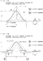
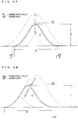
- variable valve mechanism can merely change a lift curve C such that a ratio dL/ d ⁇ of a maximum lift amount variation dL to an operation angle variation d ⁇ is substantially constant, and thus the lift curve C is changed with its substantially similar shape, as shown in FIG. 9A or 9B . Accordingly, the maximum lift amount L is increased with the increase in the operation angle ⁇ , and is decreased with the decrease in the operation angle ⁇ . Thus, the maximum lift amount L cannot be increased with the decrease in the operation angle ⁇ , and cannot be decreased with the increase in the operation angle ⁇ .
- An object of the present invention is thus to provide a variable valve mechanism that can freely change the maximum lift amount and the operation angle.
- variable valve mechanism of the present invention is configured as defined in claim 1.
- a variable width ( ⁇ ) of the operation angle ( ⁇ ) is substantially zero, and the absolute value of the ratio (dL/d ⁇ ) for the slight change caused by the second variable device is substantially 0 mm/degree.
- the predetermined range is not limited to a particular range, and the maximum lift amount and the operation angle may be in any numerical range.
- the predetermined range covers all or most part of the variable range. It is also preferable that the predetermined range include a point at which the product of the maximum lift amount and the operation angle is maximum. Most preferably, in the case where the maximum lift amount and the operation angle both cannot be changed into zero, the predetermined range covers all the variable range; in the case where the maximum lift amount or the operation angle can be changed into zero, the predetermined range covers all the variable range except for a point of zero and a vicinity of the point.
- the maximum lift amount and the operation angle can be freely changed by changing the lift curve by using the first variable device and the second variable device. Accordingly, the maximum lift amount can be increased with the decrease in the operation angle, and can be decreased with the increase in the operation angle.
- variable valve mechanism of the present invention is not limited to a particular configuration.
- the configuration of the variable valve mechanism may include, between any one of variable valve mechanisms of Patent Documents 1 to 4 ( JP 3799944 , JP 4143012 , JP 4771874 , and JP 2007-077940 A ) and a valve, a part provided between a cam of another one of the above variable valve mechanisms and a valve .
- the variable valve mechanism of the present invention is configured as below so as to have a shorter valve system (transmission mechanism).
- the transmission mechanism has four links coupled to one another via joints .
- a first variable device is configured to shift at least a reciprocating motion direction of a predetermined joint when the valve is driven.
- a second variable device is configured to shift at least a position of the predetermined joint during a base-circle time in which a base circle of a cam acts.
- the first variable device includes a first control shaft provided so as to be rotatably controlled, a rotary lever that extends from the first control shaft in a radial direction of the first control shaft and rotates with the first control shaft, and a guide member rotatably attached to the leading end of the rotary lever so as to guide the reciprocating motion direction of the predetermined joint.
- a first control shaft provided so as to be rotatably controlled
- a rotary lever that extends from the first control shaft in a radial direction of the first control shaft and rotates with the first control shaft
- a guide member rotatably attached to the leading end of the rotary lever so as to guide the reciprocating motion direction of the predetermined joint.
- two of the four links are swingably supported on the first control shaft. This is because the first control shaft can also serve as a support shaft of the two links and thus the number of parts of the variable valve mechanism can be reduced to allowmaking the variable valve mechanism compact.
- the second variable device includes a second control shaft provided so as to be rotatably controlled, and a control cam provided on the second control shaft so as to protrude therefrom.
- the control cam pushes the predetermined joint with the rotation of the second control shaft to shift the position of the predetermined joint during the base-circle time.
- the cam may be a commonly used cam having only a main nose, but preferably may be structured as below for more effectively implementing the present invention. That is, the cam may include the main nose and a sub-nose. The sub-nose opens and closes the valve again after the main nose opens and closes the valve. The opening and closing of the valve by the sub-nose can be disabled by changing the lift curve by using the first variable device or the second variable device.
- the maximum lift amount refers to a maximum lift amount caused by the main nose and the operation angle refers to an operation angle caused by the main nose.
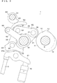
- a variable valve mechanism 1 of Embodiment 1 shown in FIGS. 1 to 7B is a mechanism that opens and closes an inlet or exhaust valve 6, provided in an internal combustion engine and having a valve spring (not shown), by periodically pushing the valve 6.
- the variable valve mechanism 1 includes a cam 10, a transmission mechanism 20, a first variable device 50, and a second variable device 60.
- the cam 10 is provided on a cam shaft 9 so as to protrude therefrom and rotates with the cam shaft 9.
- the cam shaft 9 makes one full rotation for every two full rotation (720 degrees rotation) of the internal combustion engine.
- the cam 10 includes a base circle 11 having a circular cross section, and a main nose 12 and a sub-nose 13 both protruding from the base circle 11.
- the sub-nose 13 is a nose used to open the valve 6 twice (that is, open and close the valve 6 again after the main nose 12 opens and closes the valve 6) for the purpose of exhaust gas recirculation (EGR) or the like.
- EGR exhaust gas recirculation
- the sub-nose 13 drives the valve 6 with a local-maximum lift amount Ls smaller than a maximum lift amount L of the main nose 12, and with an operation angle ⁇ s smaller than an operation angle ⁇ (i.e. rotation angle range of the internal combustion engine in which the valve 6 is opened) of the main nose 12.
- the sub-nose 13 is not formed.
- the transmission mechanism 20 is a mechanism that transmits the profile of the cam 10 to the valve 6 so as to drive the valve 6. As shown in FIG. 2 etc., the transmission mechanism 20 includes four links of first to fourth links 21 to 24 (four-joint linkage) and a rocker arm 41. The first to the fourth links 21 to 24 are sequentially coupled to one another via first to third joints 31 to 33.
- the first link 21 is rotatably supported, at an end portion of the first link 21 remote from the second link 22, by a first control shaft 51 of the first variable device 50 so as to swing.
- the first joint 31 that serves as a joint between the first link 21 and the second link 22 is provided with a roller-like cam follower 36, which contacts the cam 10 and can rotate. When the cam follower 36 is pushed by the cam 10, the first link 21 swings about the first control shaft 51.
- the second and the third links 22, 23 are links that transmit the swinging force of the first link 21 to the fourth link 24.
- the second joint 32 that serves as a joint between the second link 22 and the third link 23 is provided with a roller-like rotatable slider 37.
- the fourth link 24 is rotatably supported, at an end portion of the fourth link 24 remote from the third link 23, by the first control shaft 51 so as to swing.
- the fourth link 24 is provided, in its bottom surface, with a driving surface 24a that drives the valve 6 via the rocker arm 41 when swinging.
- the rocker arm 41 is swingably supported at its base end by a lash adjuster 48, and is provided with a roller 42 at a middle portion of the rocker arm 41 in the longitudinal direction thereof .
- the roller 42 contacts the driving surface 24a of the fourth link 24 and can rotate.
- the rocker arm 41 drives the valve 6 at the leading end of the rocker arm 41.
- the four links 21 to 24 are provided with return springs (not shown) used to bias the links 21 to 24 toward a return direction that is opposite to a lift direction (in which the valve 6 is lifted).
- the first variable device 50 is a device that mainly changes the maximum lift amount L of a lift curve C.
- the lift curve C indicates a lift amount of the valve 6 corresponding to a rotation angle of the internal combustion engine. Note that the first variable device 50 does not change the maximum lift amount L to zero.
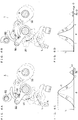
- the first variable device 50 continuously shifts a reciprocating motion direction D of the second joint 32 when the valve is driven, without shifting an initial position of the second joint 32 (i.e. position during the base-circle time in which the base circle 11 of the cam 10 acts).
- the first variable device 50 thus continuously changes the maximum lift amount L without substantially changing the operation angle ⁇ , as shown in FIG. 7A etc.
- a variable width ⁇ of the operation angle ⁇ is substantially zero. Therefore, an absolute value of a ratio ⁇ L/ ⁇ of a variable width ⁇ L of the maximum lift amount L to the variable width ⁇ of the operation angle ⁇ is substantially ⁇ mm/degree. Furthermore, in any condition where the lift curve C lies within its variable range, for a slight change caused by the first variable device 50, an absolute value of a ratio dL/d ⁇ of a maximum lift amount variation dL to an operation angle variation d ⁇ is substantially ⁇ mm/degree.
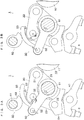
- the first variable device 50 is configured as below. That is, as shown in FIG. 2 etc. , the first variable device 50 includes the first control shaft 51, a rotary lever 52, and a guide member 53.
- the first control shaft 51 is provided so as to be rotatably controlled by a first actuator (not shown).
- the rotary lever 52 extends from the first control shaft 51 in a radial direction of the first control shaft 51 and rotates with the first control shaft 51.
- the guide member 53 is rotatably attached, at its base end, to the leading end of the rotary lever 52.
- the slider 37 contacts the guide member 53.
- the guide member 53 is a member that guides the reciprocating motion direction D of the second joint 32.
- the second variable device 60 is a device that mainly changes the operation angle ⁇ of the lift curve C. Note that the second variable device 60 does not change the operation angle ⁇ to zero. As shown in FIGS. 5A and 5B , and FIGS. 6A and 6B , the second variable device 60 continuously shifts the initial position of the second joint 32 while continuously shifting the reciprocating motion direction D of the second joint 32. The second variable device 60 thus continuously changes the operation angle ⁇ without substantially changing the maximum lift amount L, as shown in FIG. 7B .
- the variable width ⁇ L of the maximum lift amount L is substantially zero. Therefore, an absolute value of a ratio ⁇ L/ ⁇ of the variable width ⁇ L of the maximum lift amount L to the variable width ⁇ of the operation angle ⁇ is substantially 0 mm/degree. Furthermore, in any condition where the lift curve C lies within its variable range, for a slight change caused by the second variable device 60, an absolute value of a ratio dL/d ⁇ of the maximum lift amount variation dL to the operation angle variation d ⁇ is substantially 0 mm/degree.
- the second variable device 60 is configured as below. That is, as shown in FIG. 2 etc. , the second variable device 60 includes a second control shaft 61 and a control cam 63 .
- the second control shaft 61 is provided to be rotatably controlled by a second actuator (not shown) .
- the control cam 63 is provided on the second control shaft 61 so as to protrude therefrom, and rotates with the second control shaft 61.
- the control cam 63 pushes the second joint 32, via the guide member 53 and the slider 37, in a radially outward direction of the second control shaft 61.
- This causes the initial position of the second joint 32 to be shifted in the lift direction.
- the operation angle ⁇ is increased as shown in FIG. 6C .
- the maximum lift amount L is not increased. This is because the initial position of the second joint 32 is shifted while the lift direction of the reciprocating motion direction D of the second joint 32 is shifted in the radially out ward direction of the first control shaft 51, so that the increase in the maximum lift amount L is canceled.
- the second joint 32 is shifted in an radially inward direction of the second control shaft 61 by spring force of a return spring (not shown) .
- This causes the initial position of the second joint 32 to be shifted in a return direction.
- the operation angle ⁇ is decreased as shown in FIG. 6D .
- the maximum lift amount L is not decreased. This is because the initial position of the second joint 32 is shifted while the lift direction of the reciprocating motion direction D of the second joint 32 is shifted in the radially inward direction of the first control shaft 51, so that the decrease in the maximum lift amount L is canceled.
- Embodiment 1 the following effects can be produced. That is, since the maximum lift amount L can be continuously changed without changing the operation angle ⁇ by the first variable device 50, and since the operation angle ⁇ can be continuously changed without changing the maximum lift amount L by the second variable device 60, the maximum lift amount L and the operation angle ⁇ can be freely changed.
- the valve 6 can be opened one time instead of two times, with a necessary valve-driving amount kept by the main nose 12.
- Embodiment 2 shown in FIG. 8 is different from Embodiment 1 in that each part of the first variable device and each part of the second variable device of Embodiment 2 have different sizes from those of Embodiment 1. Therefore, as shown in FIG. 8A , the first variable device changes the maximum lift amount L and also slightly changes the operation angle ⁇ . In addition, as shown in FIG. 8B , the second variable device changes the operation angle ⁇ and also slightly changes the maximum lift amount L.
- variable width ⁇ L of the maximum lift amount L for the first variable device is larger than that for the second variable device; the variable width ⁇ of the operation angle ⁇ for the first variable device is smaller than that for the second variable device. Accordingly, the absolute value of the ratio ⁇ L/ ⁇ of the variable width ⁇ L of the maximum lift amount L to the variable width ⁇ of the operation angle ⁇ for the first variable device is larger than that for the second variable device. Furthermore, in any condition where the lift curve C lies within its variable range, an absolute value of the ratio dL/d ⁇ of the maximum lift amount variation dL to the operation angle variation d ⁇ for a slight change from the above any condition caused by the first variable device is larger than that for a slight change from the condition caused by the second variable device.
- the maximum lift amount L and the operation angle ⁇ can be freely changed by controlling the maximum lift amount L and the operation angle ⁇ by using the first variable device and the second variable device.
- a variable valve mechanism of an internal combustion engine includes a cam, a transmission mechanism, a first variable device that controls the transmission mechanism to continuously change at least a maximum lift amount of a lift curve indicating a lift amount of a valve that corresponds to a rotation angle of the internal combustion engine, and a second variable device that controls the transmission mechanism to continuously change at least an operation angle of the lift curve.
- the lift curve lies in any condition within a predetermined range that covers all or part of a variable range of the lift curve, an absolute value of a ratio of a maximum lift amount variation to an operation angle variation for a slight change from the condition caused by the first variable device is larger than that for a slight change from the condition caused by the second variable device.
Landscapes
- Engineering & Computer Science (AREA)
- Mechanical Engineering (AREA)
- General Engineering & Computer Science (AREA)
- Valve Device For Special Equipments (AREA)
- Output Control And Ontrol Of Special Type Engine (AREA)
- Valve-Gear Or Valve Arrangements (AREA)
Applications Claiming Priority (1)
| Application Number | Priority Date | Filing Date | Title |
|---|---|---|---|
| JP2016015158A JP6587949B2 (ja) | 2016-01-29 | 2016-01-29 | 内燃機関の可変動弁機構 |
Publications (2)
| Publication Number | Publication Date |
|---|---|
| EP3236028A1 EP3236028A1 (en) | 2017-10-25 |
| EP3236028B1 true EP3236028B1 (en) | 2019-10-23 |
Family
ID=57281036
Family Applications (1)
| Application Number | Title | Priority Date | Filing Date |
|---|---|---|---|
| EP16197491.0A Not-in-force EP3236028B1 (en) | 2016-01-29 | 2016-11-07 | Variable valve mechanism of internal combustion engine |
Country Status (3)
| Country | Link |
|---|---|
| US (1) | US10233790B2 (enExample) |
| EP (1) | EP3236028B1 (enExample) |
| JP (1) | JP6587949B2 (enExample) |
Families Citing this family (1)
| Publication number | Priority date | Publication date | Assignee | Title |
|---|---|---|---|---|
| DE102018130428A1 (de) * | 2018-11-30 | 2020-06-04 | Bayerische Motoren Werke Aktiengesellschaft | Hubvariabler Ventiltrieb mit wenigstens zwei Arbeitslagen |
Family Cites Families (11)
| Publication number | Priority date | Publication date | Assignee | Title |
|---|---|---|---|---|
| FR226E (fr) * | 1901-12-31 | 1902-11-24 | Gueydan De Roussel | Ballon dirigeable prismo-pyramidal |
| FR2569226B1 (fr) * | 1984-08-16 | 1988-01-29 | Deliaval Jean Luc | Procede et dispositif de modification d'une loi de mouvement, telle qu'une loi de levee de soupapes |
| JP3799944B2 (ja) | 2000-03-21 | 2006-07-19 | トヨタ自動車株式会社 | 内燃機関の可変動弁機構および吸気量制御装置 |
| JP4143012B2 (ja) | 2003-06-30 | 2008-09-03 | 株式会社オティックス | 可変動弁機構 |
| JP2006046111A (ja) * | 2004-08-02 | 2006-02-16 | Toyota Motor Corp | 内燃機関の可変動弁機構 |
| JP4771874B2 (ja) | 2005-09-15 | 2011-09-14 | 株式会社オティックス | 可変動弁機構 |
| JP2007077940A (ja) | 2005-09-15 | 2007-03-29 | Otics Corp | 可変動弁機構 |
| US7765965B2 (en) * | 2007-06-07 | 2010-08-03 | Manousos Pattakos | Fully variable valve actuation |
| JP4571962B2 (ja) * | 2007-08-03 | 2010-10-27 | 本田技研工業株式会社 | プラントの制御装置 |
| JP4896934B2 (ja) * | 2008-07-11 | 2012-03-14 | 日立オートモティブシステムズ株式会社 | 内燃機関の可変動弁装置 |
| JP5533781B2 (ja) * | 2011-05-13 | 2014-06-25 | トヨタ自動車株式会社 | 内燃機関の可変動弁装置 |
-
2016
- 2016-01-29 JP JP2016015158A patent/JP6587949B2/ja not_active Expired - Fee Related
- 2016-11-07 EP EP16197491.0A patent/EP3236028B1/en not_active Not-in-force
- 2016-11-30 US US15/365,661 patent/US10233790B2/en not_active Expired - Fee Related
Non-Patent Citations (1)
| Title |
|---|
| None * |
Also Published As
| Publication number | Publication date |
|---|---|
| EP3236028A1 (en) | 2017-10-25 |
| US20170218795A1 (en) | 2017-08-03 |
| JP2017133446A (ja) | 2017-08-03 |
| US10233790B2 (en) | 2019-03-19 |
| JP6587949B2 (ja) | 2019-10-09 |
Similar Documents
| Publication | Publication Date | Title |
|---|---|---|
| EP1105627B1 (en) | Variable valve timing mechanism | |
| US8312849B2 (en) | Dual intake valve system with one deactivation valve and one multi-lift valve for swirl enhancement | |
| US20170002698A1 (en) | Valve train assembly | |
| KR101234651B1 (ko) | 연속 가변 밸브 리프트 장치 | |
| EP1605142A1 (en) | Variable valve mechanism for internal combustion engine | |
| JP2003172112A (ja) | 内燃機関の可変動弁装置 | |
| KR100962194B1 (ko) | 연속 가변 밸브 리프트 시스템 | |
| US10605125B2 (en) | Switching rocker arm | |
| KR101209723B1 (ko) | 연속 가변 밸브 리프트 장치 | |
| US7640900B2 (en) | Variable valve operating device | |
| US6971355B2 (en) | Variable lift and duration device for poppet valves | |
| EP3236028B1 (en) | Variable valve mechanism of internal combustion engine | |
| US7314029B2 (en) | Variable valve timing device adapted for internal combustion engine | |
| KR100897263B1 (ko) | 무단 가변 밸브 리프트 장치 | |
| KR101251494B1 (ko) | 무단 가변 밸브 리프트 장치 | |
| JP4871310B2 (ja) | 内燃機関の可変動弁機構 | |
| US7302923B2 (en) | Variable valve timing device adapted for internal combustion engine | |
| KR100986075B1 (ko) | 연속 가변 밸브 리프트 | |
| KR100921801B1 (ko) | 무단 가변 밸브 리프트 장치 |
Legal Events
| Date | Code | Title | Description |
|---|---|---|---|
| PUAI | Public reference made under article 153(3) epc to a published international application that has entered the european phase |
Free format text: ORIGINAL CODE: 0009012 |
|
| STAA | Information on the status of an ep patent application or granted ep patent |
Free format text: STATUS: THE APPLICATION HAS BEEN PUBLISHED |
|
| AK | Designated contracting states |
Kind code of ref document: A1 Designated state(s): AL AT BE BG CH CY CZ DE DK EE ES FI FR GB GR HR HU IE IS IT LI LT LU LV MC MK MT NL NO PL PT RO RS SE SI SK SM TR |
|
| AX | Request for extension of the european patent |
Extension state: BA ME |
|
| STAA | Information on the status of an ep patent application or granted ep patent |
Free format text: STATUS: REQUEST FOR EXAMINATION WAS MADE |
|
| 17P | Request for examination filed |
Effective date: 20180116 |
|
| RBV | Designated contracting states (corrected) |
Designated state(s): AL AT BE BG CH CY CZ DE DK EE ES FI FR GB GR HR HU IE IS IT LI LT LU LV MC MK MT NL NO PL PT RO RS SE SI SK SM TR |
|
| STAA | Information on the status of an ep patent application or granted ep patent |
Free format text: STATUS: EXAMINATION IS IN PROGRESS |
|
| 17Q | First examination report despatched |
Effective date: 20180905 |
|
| GRAP | Despatch of communication of intention to grant a patent |
Free format text: ORIGINAL CODE: EPIDOSNIGR1 |
|
| STAA | Information on the status of an ep patent application or granted ep patent |
Free format text: STATUS: GRANT OF PATENT IS INTENDED |
|
| INTG | Intention to grant announced |
Effective date: 20190506 |
|
| GRAS | Grant fee paid |
Free format text: ORIGINAL CODE: EPIDOSNIGR3 |
|
| GRAA | (expected) grant |
Free format text: ORIGINAL CODE: 0009210 |
|
| STAA | Information on the status of an ep patent application or granted ep patent |
Free format text: STATUS: THE PATENT HAS BEEN GRANTED |
|
| AK | Designated contracting states |
Kind code of ref document: B1 Designated state(s): AL AT BE BG CH CY CZ DE DK EE ES FI FR GB GR HR HU IE IS IT LI LT LU LV MC MK MT NL NO PL PT RO RS SE SI SK SM TR |
|
| REG | Reference to a national code |
Ref country code: GB Ref legal event code: FG4D |
|
| REG | Reference to a national code |
Ref country code: CH Ref legal event code: EP |
|
| REG | Reference to a national code |
Ref country code: IE Ref legal event code: FG4D |
|
| REG | Reference to a national code |
Ref country code: DE Ref legal event code: R096 Ref document number: 602016022831 Country of ref document: DE |
|
| REG | Reference to a national code |
Ref country code: AT Ref legal event code: REF Ref document number: 1193871 Country of ref document: AT Kind code of ref document: T Effective date: 20191115 |
|
| REG | Reference to a national code |
Ref country code: NL Ref legal event code: MP Effective date: 20191023 |
|
| REG | Reference to a national code |
Ref country code: LT Ref legal event code: MG4D |
|
| PG25 | Lapsed in a contracting state [announced via postgrant information from national office to epo] |
Ref country code: PT Free format text: LAPSE BECAUSE OF FAILURE TO SUBMIT A TRANSLATION OF THE DESCRIPTION OR TO PAY THE FEE WITHIN THE PRESCRIBED TIME-LIMIT Effective date: 20200224 Ref country code: BG Free format text: LAPSE BECAUSE OF FAILURE TO SUBMIT A TRANSLATION OF THE DESCRIPTION OR TO PAY THE FEE WITHIN THE PRESCRIBED TIME-LIMIT Effective date: 20200123 Ref country code: NO Free format text: LAPSE BECAUSE OF FAILURE TO SUBMIT A TRANSLATION OF THE DESCRIPTION OR TO PAY THE FEE WITHIN THE PRESCRIBED TIME-LIMIT Effective date: 20200123 Ref country code: FI Free format text: LAPSE BECAUSE OF FAILURE TO SUBMIT A TRANSLATION OF THE DESCRIPTION OR TO PAY THE FEE WITHIN THE PRESCRIBED TIME-LIMIT Effective date: 20191023 Ref country code: GR Free format text: LAPSE BECAUSE OF FAILURE TO SUBMIT A TRANSLATION OF THE DESCRIPTION OR TO PAY THE FEE WITHIN THE PRESCRIBED TIME-LIMIT Effective date: 20200124 Ref country code: PL Free format text: LAPSE BECAUSE OF FAILURE TO SUBMIT A TRANSLATION OF THE DESCRIPTION OR TO PAY THE FEE WITHIN THE PRESCRIBED TIME-LIMIT Effective date: 20191023 Ref country code: LV Free format text: LAPSE BECAUSE OF FAILURE TO SUBMIT A TRANSLATION OF THE DESCRIPTION OR TO PAY THE FEE WITHIN THE PRESCRIBED TIME-LIMIT Effective date: 20191023 Ref country code: SE Free format text: LAPSE BECAUSE OF FAILURE TO SUBMIT A TRANSLATION OF THE DESCRIPTION OR TO PAY THE FEE WITHIN THE PRESCRIBED TIME-LIMIT Effective date: 20191023 Ref country code: NL Free format text: LAPSE BECAUSE OF FAILURE TO SUBMIT A TRANSLATION OF THE DESCRIPTION OR TO PAY THE FEE WITHIN THE PRESCRIBED TIME-LIMIT Effective date: 20191023 Ref country code: LT Free format text: LAPSE BECAUSE OF FAILURE TO SUBMIT A TRANSLATION OF THE DESCRIPTION OR TO PAY THE FEE WITHIN THE PRESCRIBED TIME-LIMIT Effective date: 20191023 |
|
| PG25 | Lapsed in a contracting state [announced via postgrant information from national office to epo] |
Ref country code: HR Free format text: LAPSE BECAUSE OF FAILURE TO SUBMIT A TRANSLATION OF THE DESCRIPTION OR TO PAY THE FEE WITHIN THE PRESCRIBED TIME-LIMIT Effective date: 20191023 Ref country code: IS Free format text: LAPSE BECAUSE OF FAILURE TO SUBMIT A TRANSLATION OF THE DESCRIPTION OR TO PAY THE FEE WITHIN THE PRESCRIBED TIME-LIMIT Effective date: 20200224 Ref country code: RS Free format text: LAPSE BECAUSE OF FAILURE TO SUBMIT A TRANSLATION OF THE DESCRIPTION OR TO PAY THE FEE WITHIN THE PRESCRIBED TIME-LIMIT Effective date: 20191023 |
|
| PG25 | Lapsed in a contracting state [announced via postgrant information from national office to epo] |
Ref country code: AL Free format text: LAPSE BECAUSE OF FAILURE TO SUBMIT A TRANSLATION OF THE DESCRIPTION OR TO PAY THE FEE WITHIN THE PRESCRIBED TIME-LIMIT Effective date: 20191023 |
|
| REG | Reference to a national code |
Ref country code: CH Ref legal event code: PL |
|
| REG | Reference to a national code |
Ref country code: DE Ref legal event code: R097 Ref document number: 602016022831 Country of ref document: DE |
|
| PG2D | Information on lapse in contracting state deleted |
Ref country code: IS |
|
| PG25 | Lapsed in a contracting state [announced via postgrant information from national office to epo] |
Ref country code: DK Free format text: LAPSE BECAUSE OF FAILURE TO SUBMIT A TRANSLATION OF THE DESCRIPTION OR TO PAY THE FEE WITHIN THE PRESCRIBED TIME-LIMIT Effective date: 20191023 Ref country code: ES Free format text: LAPSE BECAUSE OF FAILURE TO SUBMIT A TRANSLATION OF THE DESCRIPTION OR TO PAY THE FEE WITHIN THE PRESCRIBED TIME-LIMIT Effective date: 20191023 Ref country code: EE Free format text: LAPSE BECAUSE OF FAILURE TO SUBMIT A TRANSLATION OF THE DESCRIPTION OR TO PAY THE FEE WITHIN THE PRESCRIBED TIME-LIMIT Effective date: 20191023 Ref country code: CH Free format text: LAPSE BECAUSE OF NON-PAYMENT OF DUE FEES Effective date: 20191130 Ref country code: RO Free format text: LAPSE BECAUSE OF FAILURE TO SUBMIT A TRANSLATION OF THE DESCRIPTION OR TO PAY THE FEE WITHIN THE PRESCRIBED TIME-LIMIT Effective date: 20191023 Ref country code: CZ Free format text: LAPSE BECAUSE OF FAILURE TO SUBMIT A TRANSLATION OF THE DESCRIPTION OR TO PAY THE FEE WITHIN THE PRESCRIBED TIME-LIMIT Effective date: 20191023 Ref country code: LI Free format text: LAPSE BECAUSE OF NON-PAYMENT OF DUE FEES Effective date: 20191130 Ref country code: LU Free format text: LAPSE BECAUSE OF NON-PAYMENT OF DUE FEES Effective date: 20191107 Ref country code: MC Free format text: LAPSE BECAUSE OF FAILURE TO SUBMIT A TRANSLATION OF THE DESCRIPTION OR TO PAY THE FEE WITHIN THE PRESCRIBED TIME-LIMIT Effective date: 20191023 Ref country code: IS Free format text: LAPSE BECAUSE OF FAILURE TO SUBMIT A TRANSLATION OF THE DESCRIPTION OR TO PAY THE FEE WITHIN THE PRESCRIBED TIME-LIMIT Effective date: 20200223 |
|
| REG | Reference to a national code |
Ref country code: AT Ref legal event code: MK05 Ref document number: 1193871 Country of ref document: AT Kind code of ref document: T Effective date: 20191023 |
|
| REG | Reference to a national code |
Ref country code: BE Ref legal event code: MM Effective date: 20191130 |
|
| PLBE | No opposition filed within time limit |
Free format text: ORIGINAL CODE: 0009261 |
|
| STAA | Information on the status of an ep patent application or granted ep patent |
Free format text: STATUS: NO OPPOSITION FILED WITHIN TIME LIMIT |
|
| PG25 | Lapsed in a contracting state [announced via postgrant information from national office to epo] |
Ref country code: IT Free format text: LAPSE BECAUSE OF FAILURE TO SUBMIT A TRANSLATION OF THE DESCRIPTION OR TO PAY THE FEE WITHIN THE PRESCRIBED TIME-LIMIT Effective date: 20191023 Ref country code: SM Free format text: LAPSE BECAUSE OF FAILURE TO SUBMIT A TRANSLATION OF THE DESCRIPTION OR TO PAY THE FEE WITHIN THE PRESCRIBED TIME-LIMIT Effective date: 20191023 Ref country code: SK Free format text: LAPSE BECAUSE OF FAILURE TO SUBMIT A TRANSLATION OF THE DESCRIPTION OR TO PAY THE FEE WITHIN THE PRESCRIBED TIME-LIMIT Effective date: 20191023 |
|
| 26N | No opposition filed |
Effective date: 20200724 |
|
| PG25 | Lapsed in a contracting state [announced via postgrant information from national office to epo] |
Ref country code: IE Free format text: LAPSE BECAUSE OF NON-PAYMENT OF DUE FEES Effective date: 20191107 |
|
| PG25 | Lapsed in a contracting state [announced via postgrant information from national office to epo] |
Ref country code: BE Free format text: LAPSE BECAUSE OF NON-PAYMENT OF DUE FEES Effective date: 20191130 Ref country code: AT Free format text: LAPSE BECAUSE OF FAILURE TO SUBMIT A TRANSLATION OF THE DESCRIPTION OR TO PAY THE FEE WITHIN THE PRESCRIBED TIME-LIMIT Effective date: 20191023 Ref country code: SI Free format text: LAPSE BECAUSE OF FAILURE TO SUBMIT A TRANSLATION OF THE DESCRIPTION OR TO PAY THE FEE WITHIN THE PRESCRIBED TIME-LIMIT Effective date: 20191023 |
|
| PG25 | Lapsed in a contracting state [announced via postgrant information from national office to epo] |
Ref country code: CY Free format text: LAPSE BECAUSE OF FAILURE TO SUBMIT A TRANSLATION OF THE DESCRIPTION OR TO PAY THE FEE WITHIN THE PRESCRIBED TIME-LIMIT Effective date: 20191023 |
|
| PG25 | Lapsed in a contracting state [announced via postgrant information from national office to epo] |
Ref country code: MT Free format text: LAPSE BECAUSE OF FAILURE TO SUBMIT A TRANSLATION OF THE DESCRIPTION OR TO PAY THE FEE WITHIN THE PRESCRIBED TIME-LIMIT Effective date: 20191023 Ref country code: HU Free format text: LAPSE BECAUSE OF FAILURE TO SUBMIT A TRANSLATION OF THE DESCRIPTION OR TO PAY THE FEE WITHIN THE PRESCRIBED TIME-LIMIT; INVALID AB INITIO Effective date: 20161107 |
|
| PGFP | Annual fee paid to national office [announced via postgrant information from national office to epo] |
Ref country code: GB Payment date: 20210930 Year of fee payment: 6 |
|
| PGFP | Annual fee paid to national office [announced via postgrant information from national office to epo] |
Ref country code: DE Payment date: 20210929 Year of fee payment: 6 |
|
| PGFP | Annual fee paid to national office [announced via postgrant information from national office to epo] |
Ref country code: FR Payment date: 20211018 Year of fee payment: 6 |
|
| PG25 | Lapsed in a contracting state [announced via postgrant information from national office to epo] |
Ref country code: TR Free format text: LAPSE BECAUSE OF FAILURE TO SUBMIT A TRANSLATION OF THE DESCRIPTION OR TO PAY THE FEE WITHIN THE PRESCRIBED TIME-LIMIT Effective date: 20191023 |
|
| PG25 | Lapsed in a contracting state [announced via postgrant information from national office to epo] |
Ref country code: MK Free format text: LAPSE BECAUSE OF FAILURE TO SUBMIT A TRANSLATION OF THE DESCRIPTION OR TO PAY THE FEE WITHIN THE PRESCRIBED TIME-LIMIT Effective date: 20191023 |
|
| REG | Reference to a national code |
Ref country code: DE Ref legal event code: R119 Ref document number: 602016022831 Country of ref document: DE |
|
| GBPC | Gb: european patent ceased through non-payment of renewal fee |
Effective date: 20221107 |
|
| PG25 | Lapsed in a contracting state [announced via postgrant information from national office to epo] |
Ref country code: GB Free format text: LAPSE BECAUSE OF NON-PAYMENT OF DUE FEES Effective date: 20221107 Ref country code: DE Free format text: LAPSE BECAUSE OF NON-PAYMENT OF DUE FEES Effective date: 20230601 |
|
| PG25 | Lapsed in a contracting state [announced via postgrant information from national office to epo] |
Ref country code: FR Free format text: LAPSE BECAUSE OF NON-PAYMENT OF DUE FEES Effective date: 20221130 |