EP3235996A1 - System und verfahren zur trockenverklebung von rahmenfüllungen - Google Patents
System und verfahren zur trockenverklebung von rahmenfüllungen Download PDFInfo
- Publication number
- EP3235996A1 EP3235996A1 EP17166916.1A EP17166916A EP3235996A1 EP 3235996 A1 EP3235996 A1 EP 3235996A1 EP 17166916 A EP17166916 A EP 17166916A EP 3235996 A1 EP3235996 A1 EP 3235996A1
- Authority
- EP
- European Patent Office
- Prior art keywords
- filling
- frame
- adhesive tape
- dry
- glazing
- Prior art date
- Legal status (The legal status is an assumption and is not a legal conclusion. Google has not performed a legal analysis and makes no representation as to the accuracy of the status listed.)
- Granted
Links
Images

Classifications
-
- E—FIXED CONSTRUCTIONS
- E06—DOORS, WINDOWS, SHUTTERS, OR ROLLER BLINDS IN GENERAL; LADDERS
- E06B—FIXED OR MOVABLE CLOSURES FOR OPENINGS IN BUILDINGS, VEHICLES, FENCES OR LIKE ENCLOSURES IN GENERAL, e.g. DOORS, WINDOWS, BLINDS, GATES
- E06B3/00—Window sashes, door leaves, or like elements for closing wall or like openings; Layout of fixed or moving closures, e.g. windows in wall or like openings; Features of rigidly-mounted outer frames relating to the mounting of wing frames
- E06B3/54—Fixing of glass panes or like plates
- E06B3/58—Fixing of glass panes or like plates by means of borders, cleats, or the like
- E06B3/5807—Fixing of glass panes or like plates by means of borders, cleats, or the like not adjustable
- E06B3/5814—Fixing of glass panes or like plates by means of borders, cleats, or the like not adjustable together with putty or fixed by glue
-
- E—FIXED CONSTRUCTIONS
- E06—DOORS, WINDOWS, SHUTTERS, OR ROLLER BLINDS IN GENERAL; LADDERS
- E06B—FIXED OR MOVABLE CLOSURES FOR OPENINGS IN BUILDINGS, VEHICLES, FENCES OR LIKE ENCLOSURES IN GENERAL, e.g. DOORS, WINDOWS, BLINDS, GATES
- E06B3/00—Window sashes, door leaves, or like elements for closing wall or like openings; Layout of fixed or moving closures, e.g. windows in wall or like openings; Features of rigidly-mounted outer frames relating to the mounting of wing frames
- E06B3/54—Fixing of glass panes or like plates
- E06B3/58—Fixing of glass panes or like plates by means of borders, cleats, or the like
- E06B3/62—Fixing of glass panes or like plates by means of borders, cleats, or the like of rubber-like elastic cleats
- E06B2003/627—Fixing of glass panes or like plates by means of borders, cleats, or the like of rubber-like elastic cleats with specific characteristics concerning the material
- E06B2003/6282—Fixing of glass panes or like plates by means of borders, cleats, or the like of rubber-like elastic cleats with specific characteristics concerning the material of cellular nature
-
- E—FIXED CONSTRUCTIONS
- E06—DOORS, WINDOWS, SHUTTERS, OR ROLLER BLINDS IN GENERAL; LADDERS
- E06B—FIXED OR MOVABLE CLOSURES FOR OPENINGS IN BUILDINGS, VEHICLES, FENCES OR LIKE ENCLOSURES IN GENERAL, e.g. DOORS, WINDOWS, BLINDS, GATES
- E06B3/00—Window sashes, door leaves, or like elements for closing wall or like openings; Layout of fixed or moving closures, e.g. windows in wall or like openings; Features of rigidly-mounted outer frames relating to the mounting of wing frames
- E06B3/54—Fixing of glass panes or like plates
- E06B3/58—Fixing of glass panes or like plates by means of borders, cleats, or the like
- E06B3/5807—Fixing of glass panes or like plates by means of borders, cleats, or the like not adjustable
- E06B3/5821—Fixing of glass panes or like plates by means of borders, cleats, or the like not adjustable hooked on or in the frame member, fixed by clips or otherwise elastically fixed
Definitions
- Glued glazings are generally distinguished between wet glazing or wet gluing with a liquid adhesive that cures only after the onset of glazing and glued dry glazing (dry gluing) by means of a double-sided adhesive tape.
- double-sided adhesive tapes in particular the positioning and orientation of the filling in the frame, typically with glazing blocks, after the onset of the glazing is problematic.
- Object of the present invention is to provide a generic system and a method for dry bonding a filling in a frame that on the one hand allows easy alignment and fixation of the filling in the frame and on the other hand allows an immediately resilient dry bonding of the filling in the frame.
- the invention achieves this object by a system according to claim 1, or a method according to claim 5, preferably in conjunction with one or more of the features of the dependent claims.
- the core of the present invention is to prevent premature contact between the filling and the adhesive tape by means of a plurality of spaced-apart compliant spacing means until the alignment or blocking of the filling in the frame is completed. After aligning or blocking the filling in the frame, the filling is then pressed against the adhesive tapes with elastic and / or plastic deformation of the spacer means used according to the invention, so that the filling is glued to the frame without delay.
- the buffers are made of open-cell foam, in particular with very fine pores. Such open-cell foams have a damped, delayed release yielding behavior with a corresponding pressure load. Open-celled, uncrosslinked or preferably crosslinked polyolefin foams and foams of rubber-like elastomers are particularly suitable as material for foam buffers.
- the apparent density is preferably between 30 and 200 kg / m 3 .
- the spacing means are advantageously mounted in the fold region of the glazing receiving frame below or partially overlapping with the adhesive tape, so that even at the locations where the spacing means are used, the glazing is glued to the adhesive tape after compressing the spacing means.
- the adhesive tape is used all around and serves on the outside of the window preferably as a single seal between the filling and the frame.
- the center seal profile system used in the embodiment described below is known per se and essentially comprises the frame profile 1 made of PVC-u, the sash profile 2, also made of PVC-u, and an outer stop bar 5 made of aluminum, which is the outer visible surface of the sash Covering 2 and is attached to the sash profile 2. By means of screws with the sash profile 2 connected retaining clips 11 secure this stop bar 5 in position.
- the frame profile 1 is provided on its outer side with an aluminum shell 8.
- the center seal is indicated in the figures by reference numeral 9, the sash seal by reference numeral 10.
- this On the inside of the stop bar 5, this has a double-sided adhesive tape 6 over its entire length.
- This double-sided adhesive tape 6 is used for bonding with the filling 4 on the outside of the outer glass pane of the glazing, ie as so-called "Pos. 1 glazing".
- the filling 4 is a multiple glazing.
- Fig. 2 If the filling 4 is already inserted into the folding area 12, however, it is kept at a distance from the double-sided adhesive tape 6 by the buffer 7 used according to the invention and serving as a spacing means. In this position, the filling by means of known glazing blocks, possibly also with the aid of conventional block bridges, centered aligned and braced against the sash 2.
- the glazing blocks known to the person skilled in the art are not shown in the figures.
- the filling 4 is pressed against the buffer 7, whereby they are compressed so far until the filling 4 comes into contact with the double-sided adhesive tape 6 and glued. Subsequently, in a conventional manner, the glass strip 3 in the glazing bead receiving groove 13 clipped to hold the filling 4 from the inside. Since the filling 4 adheres firmly to this immediately after pressing on the adhesive tape 6, the glazed wing can easily be further processed and transported.
- the buffer 7 used in the illustrated embodiment consist of open-cell polyolefin foam a density of 60 kg / m 3 and each have a height of about 16 mm, a width of about 25 mm and a thickness of about 6 mm. Due to their fine, open-cell structure, the buffers 7 react to compressive stress for a short time with a relatively high compression hardness and thus prevent the filling 4 from spontaneously coming into contact with the adhesive tape 6. At sustained compressive stress, however, this resistance decreases due to the escape of the air contained through the open pores and is very low for once compressed foam. For smaller fillings, two buffers 7 are used on each of the four sides, with larger fillings 4 also three or four buffers 7 per side.
- buffers 7 are held by the lower portion of the double-sided adhesive tape 6 in position. It is also possible to use self-adhesive buffers 7, which are provided for example on their the stop bar 5 side facing with an adhesive adhesive and so can be positioned without touching the tape 6 on the inside of the stop bar 5.
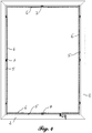
- Fig. 4 is a view of the sash from the inside before the insertion of the glazing 4 shown.
- the sash profiles 2 in the miter area are welded as usual, while the plugged-stop strips 5 butt against each other.
- the diegelfalzdichtung 10 is not shown in this Fig. For clarity.
Landscapes
- Engineering & Computer Science (AREA)
- Civil Engineering (AREA)
- Structural Engineering (AREA)
- Securing Of Glass Panes Or The Like (AREA)
Abstract
Description
- Zur Verglasung von Rahmen von Fenstern und Türen werden in zunehmendem Maße Verklebungen eingesetzt. Insbesondere bei Flügelrahmen aus Kunststoffprofilen tragen geklebte Füllungen, insbesondere geklebte Verglasungen, in erheblichem Maß zur Versteifung des Rahmens bei, so dass zusätzliche Stahlverstärkungen minimiert oder ganz vermieden werden können. Bei geklebten Verglasungen wird allgemein unterschieden zwischen einer Nassverglasung bzw. Nassverklebung mit einem flüssigen, erst nach dem Einsetzen der Verglasung aushärtenden Kleber und einer geklebten Trockenverglasung (Trockenverklebung) mittels eines doppelseitigen Klebebandes. Bei Einsatz doppelseitiger Klebebänder ist insbesondere die Positionierung und Ausrichtung der Füllung im Rahmen, typischerweise mit Verglasungsklötzen, nach dem Einsetzen der Verglasung problematisch.
- Aus der
DE 20 2010 013 012 U1 ist ein gattungsgemäßes System zur Trockenverklebung von Verglasungen mittels eines Klebebandes bekannt, bei dem mittels eines adhäsionsverzögernden Agens nach dem Einsetzen der Verglasung eine Positionierung und Fixierung der Verglasung im Rahmen mittels Verglasungsklötzen erleichtert wird. Allerdings wird die Adhäsion des Klebebandes bis zum vollständigen Verdunsten des Agens behindert, so dass die Rahmen auch nach dem Verklotzen für einen erheblichen Zeitraum noch nicht ihre endgültige Steifigkeit erreicht haben. Dieses erschwert die weitere Verarbeitung und den Transport der verglasten Rahmen erheblich. Zudem ist der Einsatz der adhäsionsverzögernden Agenzien, üblicherweise Wasser, wegen der damit verbundenen Verschmutzung der Elemente sowie des Arbeitsplatzes problematisch. - Aus der
US 3 881 290 A1 ist ein System zur Trockenverklebung einer Füllung in einem Rahmen bekannt, bei dem neben einem umlaufenden Klebeband eine umlaufende Dichtung aus Silikon verwendet wird. Ein ähnliches System ist aus derDE 10 2009 041 344 A1 bekannt. Eine zusätzliche umlaufende Dichtung neben dem Klebeband für die Trockenverglasung stellt allerdings einen erheblichen Aufwand dar. - Aufgabe der vorliegenden Erfindung ist es, ein gattungsgemäßes System und ein Verfahren zur Trockenverklebung einer Füllung in einem Rahmen zur Verfügung zu stellen, dass einerseits ein problemlose Ausrichtung und Fixierung der Füllung im Rahmen ermöglicht und andererseits eine unmittelbar belastbare Trockenverklebung der Füllung im Rahmen ermöglicht.
- Die Erfindung löst diese Aufgabe durch ein System gemäß Anspruch 1, bzw. ein Verfahren nach Anspruch 5, bevorzugt in Verbindung mit einem oder mehreren der Merkmale der abhängigen Ansprüche.
- Kern der vorliegenden Erfindung ist es, einen vorzeitigen Kontakt zwischen der Füllung und dem Klebeband mittels mehrerer, zueinander beabstandet angeordneter nachgebender Abstandsmittel so lange zu unterbinden, bis die Ausrichtung bzw. Verklotzung der Füllung im Rahmen abgeschlossen ist. Nach dem Ausrichten bzw. Verklotzen der Füllung im Rahmen wird dann die Füllung unter elastischer und/oder plastischer Verformung der erfindungsgemäß eingesetzten Abstandsmittel an die Klebebänder gedrückt, so dass die Füllung ohne Verzögerung mit dem Rahmen verklebt wird.
- Nach einer bevorzugten Ausführungsform der Erfindung werden als elastisch und oder plastisch verformbare Abstandsmittel mehrere zueinander beabstandet angeordnete Puffer aus Schaumstoff eingesetzt. Die Größe, Anzahl und Verteilung der benötigten Schaumstoff-Puffer hängt von der Härte und Konsistenz der eingesetzten Schaumstoffe ab und kann durch einfache Versuche ermittelt werden. Nach einer besonders bevorzugten Ausführungsform der Erfindung bestehen die Puffer aus offenzelligem Schaumstoff, insbesondere mit sehr feinen Poren. Solche offenzelligen Schaumstoffe weisen bei entsprechender Druckbelastung ein gedämpftes, zeitverzögert nachgebendes Verformungsverhalten auf. Als Material für Schaumstoff-Puffer eignen sich insbesondere offenzellige, unvernetzte oder bevorzugt vernetzte Polyolefin-Schaumstoffe und Schaumstoffe aus kautschukartigen Elastomeren. Die Rohdichte liegt bevorzugt zwischen 30 und 200 Kg/m3 .
- Die Abstandsmittel werden vorteilhaft im Falzbereich des die Verglasung aufnehmenden Rahmens unterhalb oder teilüberlappend mit dem Klebeband angebracht, so dass auch an den Stellen, an denen die Abstandsmittel eingesetzt werden, nach dem Komprimieren der Abstandsmittel die Verglasung mit dem Klebeband verklebt wird.
- Das Klebeband wird umlaufend eingesetzt und dient auf der Fensteraußenseite bevorzugt als einzige Dichtung zwischen der Füllung und dem Rahmen.
- Die Erfindung wird nachfolgend anhand eines Ausführungsbeispiels sowie der Zeichnung näher erläutert. Es zeigen dabei:
- Fig. 1
- einen Querschnitt durch einen Kunststoff-Fensterrahmen mit Flügelrahmen vor dem Einsetzen der Verglasung;
- Fig. 2
- einen Querschnitt durch einen Kunststoff-Fensterrahmen mit Flügelrahmen beim Einsetzen der Verglasung;
- Fig. 3
- einen Querschnitt durch einen Kunststoff-Fensterrahmen mit Flügelrahmen nach dem Einsetzen und Verklotzen der Verglasung;
- Fig. 4
- eine Ansicht auf den unverglasten Flügel von der Innenseite.
- Das in dem nachfolgend beschriebenen Ausführungsbeispiel verwendete Mitteldichtungs-Profilsystem ist an sich bekannt und umfasst im Wesentlichen das Blendrahmenprofil 1 aus PVC-u, das Flügelprofil 2, ebenfalls aus PVC-u, sowie eine äußere Anschlagleiste 5 aus Aluminium, die die äußere Sichtfläche des Flügelprofils 2 abdeckt und auf das Flügelprofil 2 aufgesteckt ist. Durch Schrauben mit dem Flügelrahmenprofil 2 verbundene Halteklipse 11 sichern diese Anschlagleiste 5 in ihrer Position. In dem dargestellten Ausführungsbeispiel ist das Blendrahmenprofil 1 auf seiner Außenseite mit einer Aluschale 8 versehen. Die Mitteldichtung ist in den Fig. mit Bezugsziffer 9, die Flügelfalzdichtung mit Bezugszeichen 10 gekennzeichnet.
- Auf der Innenseite der Anschlagleiste 5 weist diese über ihre gesamte Länge ein doppelseitiges Klebeband 6 auf. Dieses doppelseitige Klebeband 6 dient zur Verklebung mit der Füllung 4 an der Außenseite der äußeren Glasscheibe der Verglasung, also als sogenannte "Pos. 1-Verglasung". Im dargestellten Ausführungsbeispiel ist die Füllung 4 eine Mehrfachverglasung.
- In
Fig. 2 ist die Füllung 4 bereits in den Falzbereich 12 eingesetzt, wird aber durch die erfindungsgemäß eingesetzten, als Abstandsmittel dienenden Puffer 7 auf Distanz zum doppelseitigen Klebeband 6 gehalten. In dieser Position kann die Füllung mittels an sich bekannter Verglasungsklötze, gegebenenfalls auch unter Zuhilfenahme üblicher Klotzbrücken, zentriert ausgerichtet und gegenüber dem Flügelrahmen 2 verspannt werden. Die dem Fachmann geläufigen Verglasungsklötze sind in den Fig. nicht dargestellt. - Nach dem Ausrichten der Füllung 4 im Flügelrahmen 2 wird die Füllung 4 gegen die Puffer 7 gedrückt, wodurch diese soweit komprimiert werden, bis die Füllung 4 mit dem doppelseitigen Klebeband 6 in Berührung kommt und verklebt. Anschließend wird in an sich bekannter Weise die Glasleiste 3 in die Glasleisten-Aufnahmenut 13 eingeklipst, um die Füllung 4 von der Innenseite zu halten. Da die Füllung 4 unmittelbar nach dem Andrücken an das Klebeband 6 fest an diesem haftet, kann der verglaste Flügel problemlos weiterverarbeitet und transportiert werden.
- Die im dargestellten Ausführungsbeispiel verwendeten Puffer 7 bestehen aus offenzelligem Polyolefin-Schaumstoff einer Rohdichte von 60 kg/m3 und weisen jeweils einer Höhe von ca. 16 mm, eine Breite von ca. 25 mm sowie eine Dicke von ca. 6 mm auf. Durch ihre feine, offenzellige Struktur reagieren die Puffer 7 auf Druckbeanspruchung kurzzeitig mit relativ hoher Stauchhärte und verhindern so, dass die Füllung 4 spontan mit dem Klebeband 6 in Berührung kommt. Bei anhaltender Druckbeanspruchung sinkt dieser Widerstand durch das Entweichen der enthaltenen Luft durch die offenen Poren jedoch und ist bei einmal komprimiertem Schaumstoff sehr gering. Bei kleineren Füllungen werden auf jeder der vier Seiten zwei Puffer 7 eingesetzt, bei größeren Füllungen 4 auch drei oder vier Puffer 7 je Seite.
- Wie insbesondere in
Fig. 1 und 2 zu erkennen, werden die Puffer 7 durch den unteren Bereich des doppelseitigen Klebebandes 6 in Position gehalten. Es ist ebenfalls möglich, selbstklebende Puffer 7 einzusetzen, die z.B. auf ihrer der Anschlagleiste 5 zugewandten Seite mit einem Adhäsionskleber versehen sind und so auch ohne Berührung des Klebebandes 6 an der Innenseite der Anschlagleiste 5 positioniert werden können. - In
Fig. 4 ist eine Ansicht auf den Flügelrahmen von Innen vor dem Einsetzen der Verglasung 4 dargestellt. In diesem Ausführungsbeispiel sind die Flügelrahmenprofile 2 im Gehrungsbereich wie üblich verschweißt, während die aufgesteckten Anschlagleisten 5 stumpf aufeinanderstoßen. Die Flügelfalzdichtung 10 ist in dieser Fig. der Übersicht wegen nicht dargestellt. -
- 1
- Blendrahmen, Blendrahmenprofil
- 2
- Flügelrahmen, Flügelrahmenprofil
- 3
- Glasleiste
- 4
- Füllung, Verglasung
- 5
- Anschlagleiste
- 6
- Klebeband
- 7
- Puffer, Abstandsmittel
- 8
- Aluschale
- 9
- Mitteldichtung
- 10
- Falzdichtung
- 11
- Halteklips
- 12
- Falzbereich
- 13
- Glasleisten-Aufnahmenut
Claims (9)
- System zur Trockenverklebung einer Füllung (4) in einem Rahmen (2), umfassend einen Rahmen (2) mit wenigstens einem Falzbereich (12), einer Füllung (4), insbesondere einer Verglasung, einer Glasleiste (3) und einem Klebeband (6), das zur Verklebung der Füllung (4) im Rahmen (2) dient, dadurch gekennzeichnet, dass das System weiterhin mehrere zueinander beabstandet angeordnete elastisch und/oder plastisch verformbare, bei Druckbeanspruchung nachgebende Abstandsmittel (7) umfasst.
- System zur Trockenverklebung nach Anspruch 1, dadurch gekennzeichnet, dass das System weiterhin Mittel zum Verklotzen und/oder Ausrichten der Füllung (4) im Falzbereich (12) aufweist.
- System zur Trockenverklebung nach Anspruch 1 oder 2, dadurch gekennzeichnet, dass als Abstandsmittel (7) Puffer aus Schaumstoff eingesetzt werden.
- System zur Trockenverklebung nach Anspruch 3, dadurch gekennzeichnet, dass die Puffer aus offenzelligem Schaumstoff bestehen.
- System zur Trockenverklebung nach einem der Ansprüche 1 bis 4, dadurch gekennzeichnet, dass das Klebeband (6) als Dichtung zwischen der Füllung (4) und dem Rahmen (2) dient.
- System zur Trockenverklebung nach einem der Ansprüche 1 bis 5, dadurch gekennzeichnet, dass die Abstandsmittel (7) als Puffer einer Breite von 15-50 mm - in Umfangsrichtung betrachtet - ausgeführt sind.
- Verfahren zur Trockenverglasung einer Füllung (4) in einem Rahmen (2) mit einem System nach einem der Ansprüche 1 bis 6, umfassend folgende Verfahrensschritte:- die Füllung (4) wird in den Falzbereich (12) des Rahmens (2) eingesetzt, wobei die zueinander beabstandet angeordneten Abstandsmittel (7) zunächst die dem Klebeband (6) zugewandte Außenseite der Füllung (4) von dem Klebeband (6) soweit auf Abstand halten, dass die Füllung (4) noch nicht mit dem Klebeband (6) verklebt,- die Füllung (4) wird im Rahmen (2) insbesondere mit Hilfe einer Verklotzung ausgerichtet,- die Füllung (4) wird im Rahmen (2) unter Verformung der Abstandsmittel (7) in Richtung des Klebebandes (6) gedrückt, wobei die dem Klebeband (6) zugewandte Außenseite der Füllung (4) mit dem Klebeband (6) dauerhaft verklebt.
- Verfahren nach Anspruch 7, dadurch gekennzeichnet, dass als Abstandsmittel (7) mehrere zueinander beabstandet angeordnete Puffer aus Schaumstoff eingesetzt werden und dass die Verformung der Abstandsmittel (7) eine dauerhafte Kompression des Schaumstoffs bewirkt.
- Verwendung eines elastisch und/oder plastisch verformbaren, bei Druckbeanspruchung nachgebenden Abstandsmittels (7) als Mittel zur temporären Beabstandung einer Füllung (4) von einem Trockenkleber.
Priority Applications (1)
| Application Number | Priority Date | Filing Date | Title |
|---|---|---|---|
| PL17166916T PL3235996T3 (pl) | 2016-04-18 | 2017-04-18 | Układ i sposób wklejania na sucho wypełnień ram |
Applications Claiming Priority (1)
| Application Number | Priority Date | Filing Date | Title |
|---|---|---|---|
| EP16165847.1A EP3235995A1 (de) | 2016-04-18 | 2016-04-18 | System und verfahren zur trockenverklebung von rahmenfüllungen |
Publications (2)
| Publication Number | Publication Date |
|---|---|
| EP3235996A1 true EP3235996A1 (de) | 2017-10-25 |
| EP3235996B1 EP3235996B1 (de) | 2020-12-16 |
Family
ID=55759544
Family Applications (2)
| Application Number | Title | Priority Date | Filing Date |
|---|---|---|---|
| EP16165847.1A Withdrawn EP3235995A1 (de) | 2016-04-18 | 2016-04-18 | System und verfahren zur trockenverklebung von rahmenfüllungen |
| EP17166916.1A Active EP3235996B1 (de) | 2016-04-18 | 2017-04-18 | System und verfahren zur trockenverklebung von rahmenfüllungen |
Family Applications Before (1)
| Application Number | Title | Priority Date | Filing Date |
|---|---|---|---|
| EP16165847.1A Withdrawn EP3235995A1 (de) | 2016-04-18 | 2016-04-18 | System und verfahren zur trockenverklebung von rahmenfüllungen |
Country Status (3)
| Country | Link |
|---|---|
| EP (2) | EP3235995A1 (de) |
| ES (1) | ES2855274T3 (de) |
| PL (1) | PL3235996T3 (de) |
Families Citing this family (1)
| Publication number | Priority date | Publication date | Assignee | Title |
|---|---|---|---|---|
| US11643866B1 (en) | 2020-12-29 | 2023-05-09 | Andersen Corporation | Retention clip assemblies, retention systems and methods |
Citations (4)
| Publication number | Priority date | Publication date | Assignee | Title |
|---|---|---|---|---|
| US3881290A (en) | 1974-04-15 | 1975-05-06 | Gen Electric | Glazed impervious sheet assembly and method of glazing |
| DE102009041344A1 (de) | 2008-11-07 | 2010-05-12 | Wertbau Gmbh & Co. Kg | Anordnung für ein Fenster, enthaltend ein Rahmenprofil und eine Verglasung |
| DE202010013012U1 (de) | 2010-11-29 | 2011-02-10 | Gealan Fenster-Systeme Gmbh | System zur Trockenverklebung von Fensterscheiben |
| US20140318050A1 (en) * | 2004-07-15 | 2014-10-30 | Abdul Lathief | Glazing system with thermal break |
-
2016
- 2016-04-18 EP EP16165847.1A patent/EP3235995A1/de not_active Withdrawn
-
2017
- 2017-04-18 EP EP17166916.1A patent/EP3235996B1/de active Active
- 2017-04-18 PL PL17166916T patent/PL3235996T3/pl unknown
- 2017-04-18 ES ES17166916T patent/ES2855274T3/es active Active
Patent Citations (4)
| Publication number | Priority date | Publication date | Assignee | Title |
|---|---|---|---|---|
| US3881290A (en) | 1974-04-15 | 1975-05-06 | Gen Electric | Glazed impervious sheet assembly and method of glazing |
| US20140318050A1 (en) * | 2004-07-15 | 2014-10-30 | Abdul Lathief | Glazing system with thermal break |
| DE102009041344A1 (de) | 2008-11-07 | 2010-05-12 | Wertbau Gmbh & Co. Kg | Anordnung für ein Fenster, enthaltend ein Rahmenprofil und eine Verglasung |
| DE202010013012U1 (de) | 2010-11-29 | 2011-02-10 | Gealan Fenster-Systeme Gmbh | System zur Trockenverklebung von Fensterscheiben |
Also Published As
| Publication number | Publication date |
|---|---|
| EP3235996B1 (de) | 2020-12-16 |
| PL3235996T3 (pl) | 2021-06-14 |
| ES2855274T3 (es) | 2021-09-23 |
| EP3235995A1 (de) | 2017-10-25 |
Similar Documents
| Publication | Publication Date | Title |
|---|---|---|
| EP1373672B1 (de) | Flügel für fenster oder eine tür | |
| AT10453U1 (de) | Laibungsanschlussprofil für an putz angrenzende bauteile | |
| DE10037667C1 (de) | Holz-Alu-Fenster | |
| EP2116682A2 (de) | Anschlussprofil für an Putz angrenzende Bauteile | |
| DE202010015743U1 (de) | Gebäudeumhüllungselement mit thermischem Isolierelement | |
| EP1106770B1 (de) | Fensterflügel und Fenster | |
| EP3235996B1 (de) | System und verfahren zur trockenverklebung von rahmenfüllungen | |
| EP1923532A2 (de) | Alu-Kunststoff-Fenster mit Klebebandfixierung | |
| EP3910154B1 (de) | Fenster mit einer schutzvorrichtung und bausatz für die schutzvorrichtung | |
| DE102017108232A1 (de) | System und Verfahren zur Trockenverklebung von Rahmenfüllungen | |
| DE3825580A1 (de) | Verfahren zum herstellen einer mehrfachverglasung und eine nach diesem verfahren hergestellte mehrfachverglasung | |
| CH440651A (de) | Halterung für Scheiben oder Platten | |
| DE10338861A1 (de) | Kunststofffenster mit eingeklebter Verglasung | |
| EP2853668B1 (de) | Halteschiene zur Aufnahme einer Glasscheibe, Glasscheibe und Befestigungsverfahren | |
| DE202010013012U1 (de) | System zur Trockenverklebung von Fensterscheiben | |
| WO2008049612A1 (de) | Tür, insbesondere feuer- und brandschutztür | |
| EP4249719A1 (de) | Anschlussprofilleiste | |
| EP2644792B1 (de) | Wandteil mit einer Verbundglasscheibe und mit einer Vorrichtung zum Verbinden von Wandteilen | |
| DE19857982B4 (de) | Fenster mit einer ein Sicherheitselement aufweisenden Fensterscheibe | |
| DE202013002504U1 (de) | Profil | |
| EP3323970B1 (de) | Verschlusselement für eine gebäudeöffnung | |
| EP2463471B1 (de) | Verfahren zur Verbindung von Verbundglasscheiben | |
| DE20102696U1 (de) | Verklotzungssystem für die Füllung eines Fenster- oder Türrahmens | |
| DE2104387A1 (de) | Gebäude - Isolierverglasung als Mittel und Verfahren | |
| AT516185A1 (de) | Anschlussprofil für an Putz angrenzende Bauteile |
Legal Events
| Date | Code | Title | Description |
|---|---|---|---|
| PUAI | Public reference made under article 153(3) epc to a published international application that has entered the european phase |
Free format text: ORIGINAL CODE: 0009012 |
|
| STAA | Information on the status of an ep patent application or granted ep patent |
Free format text: STATUS: THE APPLICATION HAS BEEN PUBLISHED |
|
| AK | Designated contracting states |
Kind code of ref document: A1 Designated state(s): AL AT BE BG CH CY CZ DE DK EE ES FI FR GB GR HR HU IE IS IT LI LT LU LV MC MK MT NL NO PL PT RO RS SE SI SK SM TR |
|
| AX | Request for extension of the european patent |
Extension state: BA ME |
|
| STAA | Information on the status of an ep patent application or granted ep patent |
Free format text: STATUS: REQUEST FOR EXAMINATION WAS MADE |
|
| 17P | Request for examination filed |
Effective date: 20180425 |
|
| RBV | Designated contracting states (corrected) |
Designated state(s): AL AT BE BG CH CY CZ DE DK EE ES FI FR GB GR HR HU IE IS IT LI LT LU LV MC MK MT NL NO PL PT RO RS SE SI SK SM TR |
|
| GRAP | Despatch of communication of intention to grant a patent |
Free format text: ORIGINAL CODE: EPIDOSNIGR1 |
|
| STAA | Information on the status of an ep patent application or granted ep patent |
Free format text: STATUS: GRANT OF PATENT IS INTENDED |
|
| INTG | Intention to grant announced |
Effective date: 20200803 |
|
| GRAS | Grant fee paid |
Free format text: ORIGINAL CODE: EPIDOSNIGR3 |
|
| GRAA | (expected) grant |
Free format text: ORIGINAL CODE: 0009210 |
|
| STAA | Information on the status of an ep patent application or granted ep patent |
Free format text: STATUS: THE PATENT HAS BEEN GRANTED |
|
| AK | Designated contracting states |
Kind code of ref document: B1 Designated state(s): AL AT BE BG CH CY CZ DE DK EE ES FI FR GB GR HR HU IE IS IT LI LT LU LV MC MK MT NL NO PL PT RO RS SE SI SK SM TR |
|
| REG | Reference to a national code |
Ref country code: GB Ref legal event code: FG4D Free format text: NOT ENGLISH |
|
| REG | Reference to a national code |
Ref country code: IE Ref legal event code: FG4D Free format text: LANGUAGE OF EP DOCUMENT: GERMAN |
|
| REG | Reference to a national code |
Ref country code: DE Ref legal event code: R096 Ref document number: 502017008665 Country of ref document: DE |
|
| REG | Reference to a national code |
Ref country code: AT Ref legal event code: REF Ref document number: 1345756 Country of ref document: AT Kind code of ref document: T Effective date: 20210115 |
|
| REG | Reference to a national code |
Ref country code: CH Ref legal event code: NV Representative=s name: TR-IP CONSULTING LLC, CH |
|
| PG25 | Lapsed in a contracting state [announced via postgrant information from national office to epo] |
Ref country code: NO Free format text: LAPSE BECAUSE OF FAILURE TO SUBMIT A TRANSLATION OF THE DESCRIPTION OR TO PAY THE FEE WITHIN THE PRESCRIBED TIME-LIMIT Effective date: 20210316 Ref country code: RS Free format text: LAPSE BECAUSE OF FAILURE TO SUBMIT A TRANSLATION OF THE DESCRIPTION OR TO PAY THE FEE WITHIN THE PRESCRIBED TIME-LIMIT Effective date: 20201216 Ref country code: FI Free format text: LAPSE BECAUSE OF FAILURE TO SUBMIT A TRANSLATION OF THE DESCRIPTION OR TO PAY THE FEE WITHIN THE PRESCRIBED TIME-LIMIT Effective date: 20201216 Ref country code: GR Free format text: LAPSE BECAUSE OF FAILURE TO SUBMIT A TRANSLATION OF THE DESCRIPTION OR TO PAY THE FEE WITHIN THE PRESCRIBED TIME-LIMIT Effective date: 20210317 |
|
| REG | Reference to a national code |
Ref country code: NL Ref legal event code: MP Effective date: 20201216 |
|
| PG25 | Lapsed in a contracting state [announced via postgrant information from national office to epo] |
Ref country code: BG Free format text: LAPSE BECAUSE OF FAILURE TO SUBMIT A TRANSLATION OF THE DESCRIPTION OR TO PAY THE FEE WITHIN THE PRESCRIBED TIME-LIMIT Effective date: 20210316 Ref country code: LV Free format text: LAPSE BECAUSE OF FAILURE TO SUBMIT A TRANSLATION OF THE DESCRIPTION OR TO PAY THE FEE WITHIN THE PRESCRIBED TIME-LIMIT Effective date: 20201216 Ref country code: SE Free format text: LAPSE BECAUSE OF FAILURE TO SUBMIT A TRANSLATION OF THE DESCRIPTION OR TO PAY THE FEE WITHIN THE PRESCRIBED TIME-LIMIT Effective date: 20201216 |
|
| PG25 | Lapsed in a contracting state [announced via postgrant information from national office to epo] |
Ref country code: NL Free format text: LAPSE BECAUSE OF FAILURE TO SUBMIT A TRANSLATION OF THE DESCRIPTION OR TO PAY THE FEE WITHIN THE PRESCRIBED TIME-LIMIT Effective date: 20201216 Ref country code: HR Free format text: LAPSE BECAUSE OF FAILURE TO SUBMIT A TRANSLATION OF THE DESCRIPTION OR TO PAY THE FEE WITHIN THE PRESCRIBED TIME-LIMIT Effective date: 20201216 |
|
| REG | Reference to a national code |
Ref country code: LT Ref legal event code: MG9D |
|
| PG25 | Lapsed in a contracting state [announced via postgrant information from national office to epo] |
Ref country code: SK Free format text: LAPSE BECAUSE OF FAILURE TO SUBMIT A TRANSLATION OF THE DESCRIPTION OR TO PAY THE FEE WITHIN THE PRESCRIBED TIME-LIMIT Effective date: 20201216 Ref country code: RO Free format text: LAPSE BECAUSE OF FAILURE TO SUBMIT A TRANSLATION OF THE DESCRIPTION OR TO PAY THE FEE WITHIN THE PRESCRIBED TIME-LIMIT Effective date: 20201216 Ref country code: PT Free format text: LAPSE BECAUSE OF FAILURE TO SUBMIT A TRANSLATION OF THE DESCRIPTION OR TO PAY THE FEE WITHIN THE PRESCRIBED TIME-LIMIT Effective date: 20210416 Ref country code: SM Free format text: LAPSE BECAUSE OF FAILURE TO SUBMIT A TRANSLATION OF THE DESCRIPTION OR TO PAY THE FEE WITHIN THE PRESCRIBED TIME-LIMIT Effective date: 20201216 Ref country code: LT Free format text: LAPSE BECAUSE OF FAILURE TO SUBMIT A TRANSLATION OF THE DESCRIPTION OR TO PAY THE FEE WITHIN THE PRESCRIBED TIME-LIMIT Effective date: 20201216 Ref country code: CZ Free format text: LAPSE BECAUSE OF FAILURE TO SUBMIT A TRANSLATION OF THE DESCRIPTION OR TO PAY THE FEE WITHIN THE PRESCRIBED TIME-LIMIT Effective date: 20201216 Ref country code: EE Free format text: LAPSE BECAUSE OF FAILURE TO SUBMIT A TRANSLATION OF THE DESCRIPTION OR TO PAY THE FEE WITHIN THE PRESCRIBED TIME-LIMIT Effective date: 20201216 |
|
| REG | Reference to a national code |
Ref country code: DE Ref legal event code: R097 Ref document number: 502017008665 Country of ref document: DE |
|
| REG | Reference to a national code |
Ref country code: ES Ref legal event code: FG2A Ref document number: 2855274 Country of ref document: ES Kind code of ref document: T3 Effective date: 20210923 |
|
| PG25 | Lapsed in a contracting state [announced via postgrant information from national office to epo] |
Ref country code: IS Free format text: LAPSE BECAUSE OF FAILURE TO SUBMIT A TRANSLATION OF THE DESCRIPTION OR TO PAY THE FEE WITHIN THE PRESCRIBED TIME-LIMIT Effective date: 20210416 |
|
| PLBE | No opposition filed within time limit |
Free format text: ORIGINAL CODE: 0009261 |
|
| STAA | Information on the status of an ep patent application or granted ep patent |
Free format text: STATUS: NO OPPOSITION FILED WITHIN TIME LIMIT |
|
| PG25 | Lapsed in a contracting state [announced via postgrant information from national office to epo] |
Ref country code: AL Free format text: LAPSE BECAUSE OF FAILURE TO SUBMIT A TRANSLATION OF THE DESCRIPTION OR TO PAY THE FEE WITHIN THE PRESCRIBED TIME-LIMIT Effective date: 20201216 |
|
| 26N | No opposition filed |
Effective date: 20210917 |
|
| PG25 | Lapsed in a contracting state [announced via postgrant information from national office to epo] |
Ref country code: DK Free format text: LAPSE BECAUSE OF FAILURE TO SUBMIT A TRANSLATION OF THE DESCRIPTION OR TO PAY THE FEE WITHIN THE PRESCRIBED TIME-LIMIT Effective date: 20201216 Ref country code: MC Free format text: LAPSE BECAUSE OF FAILURE TO SUBMIT A TRANSLATION OF THE DESCRIPTION OR TO PAY THE FEE WITHIN THE PRESCRIBED TIME-LIMIT Effective date: 20201216 |
|
| GBPC | Gb: european patent ceased through non-payment of renewal fee |
Effective date: 20210418 |
|
| PG25 | Lapsed in a contracting state [announced via postgrant information from national office to epo] |
Ref country code: LU Free format text: LAPSE BECAUSE OF NON-PAYMENT OF DUE FEES Effective date: 20210418 |
|
| REG | Reference to a national code |
Ref country code: BE Ref legal event code: MM Effective date: 20210430 |
|
| PG25 | Lapsed in a contracting state [announced via postgrant information from national office to epo] |
Ref country code: GB Free format text: LAPSE BECAUSE OF NON-PAYMENT OF DUE FEES Effective date: 20210418 |
|
| PG25 | Lapsed in a contracting state [announced via postgrant information from national office to epo] |
Ref country code: SI Free format text: LAPSE BECAUSE OF FAILURE TO SUBMIT A TRANSLATION OF THE DESCRIPTION OR TO PAY THE FEE WITHIN THE PRESCRIBED TIME-LIMIT Effective date: 20201216 |
|
| PG25 | Lapsed in a contracting state [announced via postgrant information from national office to epo] |
Ref country code: IE Free format text: LAPSE BECAUSE OF NON-PAYMENT OF DUE FEES Effective date: 20210418 |
|
| PG25 | Lapsed in a contracting state [announced via postgrant information from national office to epo] |
Ref country code: IS Free format text: LAPSE BECAUSE OF FAILURE TO SUBMIT A TRANSLATION OF THE DESCRIPTION OR TO PAY THE FEE WITHIN THE PRESCRIBED TIME-LIMIT Effective date: 20210416 |
|
| PG25 | Lapsed in a contracting state [announced via postgrant information from national office to epo] |
Ref country code: BE Free format text: LAPSE BECAUSE OF NON-PAYMENT OF DUE FEES Effective date: 20210430 |
|
| REG | Reference to a national code |
Ref country code: DE Ref legal event code: R081 Ref document number: 502017008665 Country of ref document: DE Owner name: PROFINE GMBH, DE Free format text: FORMER OWNER: PROFINE GMBH, 53840 TROISDORF, DE |
|
| PG25 | Lapsed in a contracting state [announced via postgrant information from national office to epo] |
Ref country code: HU Free format text: LAPSE BECAUSE OF FAILURE TO SUBMIT A TRANSLATION OF THE DESCRIPTION OR TO PAY THE FEE WITHIN THE PRESCRIBED TIME-LIMIT; INVALID AB INITIO Effective date: 20170418 |
|
| PG25 | Lapsed in a contracting state [announced via postgrant information from national office to epo] |
Ref country code: CY Free format text: LAPSE BECAUSE OF FAILURE TO SUBMIT A TRANSLATION OF THE DESCRIPTION OR TO PAY THE FEE WITHIN THE PRESCRIBED TIME-LIMIT Effective date: 20201216 |
|
| PG25 | Lapsed in a contracting state [announced via postgrant information from national office to epo] |
Ref country code: MK Free format text: LAPSE BECAUSE OF FAILURE TO SUBMIT A TRANSLATION OF THE DESCRIPTION OR TO PAY THE FEE WITHIN THE PRESCRIBED TIME-LIMIT Effective date: 20201216 |
|
| PG25 | Lapsed in a contracting state [announced via postgrant information from national office to epo] |
Ref country code: MT Free format text: LAPSE BECAUSE OF FAILURE TO SUBMIT A TRANSLATION OF THE DESCRIPTION OR TO PAY THE FEE WITHIN THE PRESCRIBED TIME-LIMIT Effective date: 20201216 |
|
| PGFP | Annual fee paid to national office [announced via postgrant information from national office to epo] |
Ref country code: PL Payment date: 20250411 Year of fee payment: 9 |
|
| PGFP | Annual fee paid to national office [announced via postgrant information from national office to epo] |
Ref country code: ES Payment date: 20250529 Year of fee payment: 9 |
|
| PGFP | Annual fee paid to national office [announced via postgrant information from national office to epo] |
Ref country code: IT Payment date: 20250424 Year of fee payment: 9 |
|
| PGFP | Annual fee paid to national office [announced via postgrant information from national office to epo] |
Ref country code: FR Payment date: 20250425 Year of fee payment: 9 |
|
| PGFP | Annual fee paid to national office [announced via postgrant information from national office to epo] |
Ref country code: CH Payment date: 20250501 Year of fee payment: 9 |
|
| REG | Reference to a national code |
Ref country code: CH Ref legal event code: R17 Free format text: ST27 STATUS EVENT CODE: U-0-0-R10-R17 (AS PROVIDED BY THE NATIONAL OFFICE) Effective date: 20251015 |
|
| PG25 | Lapsed in a contracting state [announced via postgrant information from national office to epo] |
Ref country code: TR Free format text: LAPSE BECAUSE OF FAILURE TO SUBMIT A TRANSLATION OF THE DESCRIPTION OR TO PAY THE FEE WITHIN THE PRESCRIBED TIME-LIMIT Effective date: 20201216 |
|
| PGFP | Annual fee paid to national office [announced via postgrant information from national office to epo] |
Ref country code: DE Payment date: 20260422 Year of fee payment: 10 |
|
| PGFP | Annual fee paid to national office [announced via postgrant information from national office to epo] |
Ref country code: AT Payment date: 20260421 Year of fee payment: 10 |