EP3235984A1 - Ferrure de fenêtre, son procédé de fabrication et fenêtre correspondante - Google Patents
Ferrure de fenêtre, son procédé de fabrication et fenêtre correspondante Download PDFInfo
- Publication number
- EP3235984A1 EP3235984A1 EP17167313.0A EP17167313A EP3235984A1 EP 3235984 A1 EP3235984 A1 EP 3235984A1 EP 17167313 A EP17167313 A EP 17167313A EP 3235984 A1 EP3235984 A1 EP 3235984A1
- Authority
- EP
- European Patent Office
- Prior art keywords
- fitting
- axerbereich
- guide
- drive rod
- window
- Prior art date
- Legal status (The legal status is an assumption and is not a legal conclusion. Google has not performed a legal analysis and makes no representation as to the accuracy of the status listed.)
- Granted
Links
- 238000004519 manufacturing process Methods 0.000 title claims abstract description 12
- 238000004080 punching Methods 0.000 claims description 19
- 230000003993 interaction Effects 0.000 claims description 4
- 238000000034 method Methods 0.000 claims description 3
- CMWTZPSULFXXJA-VIFPVBQESA-N naproxen Chemical compound C1=C([C@H](C)C(O)=O)C=CC2=CC(OC)=CC=C21 CMWTZPSULFXXJA-VIFPVBQESA-N 0.000 abstract description 42
- 230000008878 coupling Effects 0.000 description 9
- 238000010168 coupling process Methods 0.000 description 9
- 238000005859 coupling reaction Methods 0.000 description 9
- 239000000463 material Substances 0.000 description 8
- 238000006073 displacement reaction Methods 0.000 description 7
- 239000000725 suspension Substances 0.000 description 6
- 125000006850 spacer group Chemical group 0.000 description 4
- 229910000831 Steel Inorganic materials 0.000 description 3
- 230000005540 biological transmission Effects 0.000 description 3
- 238000011161 development Methods 0.000 description 3
- 238000003780 insertion Methods 0.000 description 3
- 230000037431 insertion Effects 0.000 description 3
- 239000010959 steel Substances 0.000 description 3
- 238000013461 design Methods 0.000 description 2
- 239000002184 metal Substances 0.000 description 2
- 230000002265 prevention Effects 0.000 description 2
- 230000002441 reversible effect Effects 0.000 description 2
- 238000013459 approach Methods 0.000 description 1
- 230000001066 destructive effect Effects 0.000 description 1
- 238000009434 installation Methods 0.000 description 1
Images


Classifications
-
- E—FIXED CONSTRUCTIONS
- E05—LOCKS; KEYS; WINDOW OR DOOR FITTINGS; SAFES
- E05D—HINGES OR SUSPENSION DEVICES FOR DOORS, WINDOWS OR WINGS
- E05D15/00—Suspension arrangements for wings
- E05D15/48—Suspension arrangements for wings allowing alternative movements
- E05D15/52—Suspension arrangements for wings allowing alternative movements for opening about a vertical as well as a horizontal axis
- E05D15/522—Suspension arrangements for wings allowing alternative movements for opening about a vertical as well as a horizontal axis with disconnecting means for the appropriate pivoting parts
- E05D15/523—Suspension arrangements for wings allowing alternative movements for opening about a vertical as well as a horizontal axis with disconnecting means for the appropriate pivoting parts using movable rods
-
- E—FIXED CONSTRUCTIONS
- E05—LOCKS; KEYS; WINDOW OR DOOR FITTINGS; SAFES
- E05Y—INDEXING SCHEME ASSOCIATED WITH SUBCLASSES E05D AND E05F, RELATING TO CONSTRUCTION ELEMENTS, ELECTRIC CONTROL, POWER SUPPLY, POWER SIGNAL OR TRANSMISSION, USER INTERFACES, MOUNTING OR COUPLING, DETAILS, ACCESSORIES, AUXILIARY OPERATIONS NOT OTHERWISE PROVIDED FOR, APPLICATION THEREOF
- E05Y2900/00—Application of doors, windows, wings or fittings thereof
- E05Y2900/10—Application of doors, windows, wings or fittings thereof for buildings or parts thereof
- E05Y2900/13—Type of wing
- E05Y2900/148—Windows
Definitions
- the invention relates to a fitting for a window, in particular a living room window, with a drive rod and a Axerstulpelement which has a guide device for a guide element of a Axerarms.
- the invention further relates to a method for producing a fitting and a window with a fitting.
- the fitting serves to operate the window, which can be configured as a living room window.
- an operating element of the window engages via the fitting on at least one locking element of the fitting, in particular a locking pin or locking pin.
- the fitting may have a transmission, by means of which a rotary movement of the operating element is converted into a linear movement of at least one drive rod.
- the operative connection between the control element or the transmission on the one hand and the locking element on the other hand is produced via the drive rod or via a plurality of drive rods.
- other elements may be present in the operative connection, for example a corner drive or the like.
- an opening limit for the window is realized by means of an axial shear.
- the tilting window or tilt and turn window opening in the form of tilting is provided, which takes place in particular about an axis of rotation, which preferably extends horizontally and, for example, in the region of a lower cross member of the window or cuts this.
- the cross member may be assigned to a frame of the window, in particular a frame or a sash.
- the opening limitation causes the tilting of the window is limited to a certain tilt angle.
- the Axerarm preferably attacks on the one hand on the frame and on the other hand on the sash. The latter takes place for example via the Axerstulpelement or its guide device.
- the Axerschere can alternatively be referred to as Ausstellschere, the Axerstulpelement as Ausstellscherenelement.
- the drive rod is multi-piece and has an Axer Scheme and at least one connected to the Axer Scheme, perpendicular to a longitudinal central axis of the Axer Schemes offset to this arranged connection area, wherein the Axerstulpelement is arranged at least partially adjacent to the Axer Scheme and adjacent to the connection area and has at least one retaining element which engages in at least one position in a passage recess of the Axer Schemes.
- the drive rod is arranged in the region of the Axerstulpelements, in particular it is applied to this.
- the drive rod can also be referred to as Axertreibstange.
- the production of the fitting can be complicated, in particular due to the length of the drive rod or the Axerstulpelements. It can be provided to integrate the drive rod in the Axerstulpelement, wherein the Axerstulpelement serves as a cover rail for the drive rod. In such an embodiment, however, a cranking of the Axerstulpelements can be necessary to produce complicated.
- the drive rod is usually made by punching, being formed with a certain length and a certain width. The longer the drive rod, the more difficult it is to bring them by punching to the specific width without unintentional dimensional deviations occur.
- the drive rod is composed at least of the Axer Scheme and at least one connection area.
- the connection area is connected to the axer area, in particular connected rigidly and / or non-detachably. Under the latter is to be understood that a release of the connection between the Axer Scheme and the connection area not without damage, so at least not reversible, is feasible.
- the Axer Scheme and the connection area are offset from one another. The offset is perpendicular with respect the longitudinal central axis of the Axer Studentss before.
- the connection region is preferably arranged above the axis region. For example, the connection region is at least partially located on the axis region.
- the Axerstulpelement now lies at least partially on the Axer Geb the drive rod. In this case, it is arranged adjacent to the connection region, in particular in the axial direction adjacent to the longitudinal central axis. It can be provided that a longitudinal center axis of the connection region extends through the Axerstulpelement, so this cuts.
- the Axerstulpelement has the at least one retaining element. By means of the retaining element, the Axerstulpelement is attached to the frame of the window or fastened.
- the holding element passes through the passage recess of the Axer Universitiess in at least one position at least partially, thus engages in this. In other words, a longitudinal central axis of the retaining element extends through the passage recess.
- the retaining element does not extend as far as the frame in a pre-assembly position present before assembly of the fitting, or merely protrudes into the passage recess, so it does not pass through it.
- it passes through the through-passage in an after-assembly post-assembly position to fix the Axerstulpelement respect to the frame, at least in one direction.
- the holding element is thus displaceable, in particular between a plurality of different positions and engages in at least one of the positions in the passage recess, so protrudes into it, wherein the positions include, for example, at least the pre-assembly and the post-assembly.
- the displacement of the retaining element takes place in particular during the assembly of the fitting, in particular for fixing the Axerstulpelements respect to the frame.
- the drive rod as a whole ie both the axis region and the at least one connection region, should be mounted so as to be displaceable on the frame of the window in the axial direction.
- the Axerstulpelement is fixed to the frame after assembly, in particular a spar of the frame, arranged.
- a displacement of the Axerstulpelements is prevented with respect to the frame at least in the axial direction, so that the Axerstulpelement is fixed at least in the axial direction.
- the retaining element is provided.
- it preferably passes through the passage recess and engages in the frame.
- the passage recess of the Axer rios the drive rod, through which the holding element, starting from the Axerstulpelement the frame counteract, be elongated in the axial direction, so for example as a slot present.
- the drive rod is associated with the Axerstulpelement and insofar can be referred to as Axertreibstange.
- the drive rod is connectable at least on one side with a further element of the fitting, for example a further drive rod and / or a corner drive.
- the connection area is preferably provided.
- the connection region on its side remote from the axial region in the axial direction has a coupling device for coupling the drive rod to the further drive rod and / or the corner drive.
- the coupling device thus serves to produce an operative connection between the drive rod on the one hand and the further drive rod or the corner deflection on the other.
- the coupling device can be designed, for example, as a toothing or as a suspension opening.
- a counter toothing can be provided on the further drive rod or corner drive, which counteracts the force transmission with the toothing.
- the toothing is designed as an external toothing, while the counter toothing is in the form of an internal toothing.
- the external teeth preferably has two parallel rows of teeth, the teeth of which are directed away from each other. In the internal toothing two parallel spaced rows of teeth are preferably also provided, the teeth, however, are facing each other or to run towards each other.
- the drive rod has only one connection area.
- a connection region is present in the axial direction on both sides of the axis region.
- the guide device is arranged on an axial rail of the Axerstulpelements, which rests slidably on the Axer Geb the drive rod.
- the guide device serves to guide the Axerarms or the guide element of the Axerarms.
- the guide device is arranged on the Axer rail or fixed thereto.
- the Axer rail is preferably adjacent to the terminal portion of the drive rod before, in particular, it is aligned with this. If a plurality of connection regions are provided on the axial region, then the axial rail can be arranged between these several connection regions, in particular in the axial direction in each case spaced from these.
- the Axer rail slidably engages the Axer Geb the drive rod.
- connection region extends through the axial rail or vice versa.
- a longitudinal guide opening is formed, which is penetrated by a fixed to the Axer Anlagen the drive rod longitudinal guide element, wherein a head of the longitudinal guide member slidably abuts on a side facing away from the Axer gleich edge of the longitudinal guide opening.
- the drive rail it is displaceably mounted on the Axer rail.
- the longitudinal guide opening and the longitudinal guide element are provided.
- the longitudinal guide opening is in the Axerstulpelement, preferably in the Axer rail before.
- the longitudinal guide opening is penetrated by the longitudinal guide element, which is fastened on the one hand to the Axer Geb the drive rod and on the other hand has the head.
- This head engages over the Axerstulpelement or the Axer rail on the side facing away from the Axer area.
- the head abuts in regions at the edge of the longitudinal guide opening.
- the guide means by means of a connecting element form-fitting manner with the Axerschiene, in particular by riveting or caulking, is connected.
- a positive connection using the connecting element is provided.
- the connecting element is designed, for example, in one piece with the guide device. Of course, however, it can also be configured as a separate element from the guide device.
- the positive connection is provided in particular by a forming of the connecting element.
- the guide device is riveted or caulked to the Axerschiene, in the former case, the connecting element is in the form of a rivet.
- a development of the invention provides that the connecting element protrudes into the passage recess, in particular there has a form-fitting region.
- the guide device is provided on the side facing away from the Axer Scheme the drive rod side of the Axer rail.
- the Axer rail is on the one hand to the guide means and opposite on the other hand to the Axer region of the drive rod.
- the connecting element passes through the Axer rail, starting from the guide device and projects into the passage recess of the Axer gleichs, in which also the holding element can be arranged at least partially.
- the form-fitting region of the connecting element is arranged in the through-passage.
- the positive-locking region is to be understood as meaning an area of the connecting element which engages behind the axial rail on its side opposite the guide device, so that the guide device is connected in a form-fitting manner to the axial rail via the connecting element.
- the form-fitting region can be, for example, a closing head of the rivet or a region of the connecting element deformed by caulking.
- the connecting element is expanded to form the positive connection region on its projecting into the passage recess side, for example, by wobbling or the like.
- a further preferred embodiment of the invention provides that an auxiliary arm for the Axerarm is rotatably mounted on the Axerstulpelement. After assembly of the fitting, the auxiliary arm engages on the one hand on the Axerstulpelement and on the other hand on the Axerarm, in particular it is rotatably mounted on both.
- the auxiliary arm ensures reliable and comfortable operation of the window, even with long axles.
- a further embodiment of the invention provides that the Axer Scheme is permanently attached by means of a fastener, in particular a rivet, to the connection area.
- the Axer Scheme and the connection area of the drive rod should be permanently connected to one another.
- a release or a reversible release of the Axer Schemes of the connection area is not provided or at least not non-destructive.
- the attachment is provided by means of the fastener, which may be in the form of a rivet, for example. However, other types of fasteners may of course be provided.
- the fastening element has a rear grip element, which cooperates in at least one position of the drive rod with a arranged on the Axerarm Schugriffshafenelement for setting the Axerarms in at least one direction.
- the fastener combines two different functions. On the one hand, it serves to fasten the axle area to the connection area or vice versa. On the other hand, it should serve a locking of the Axerarms. For this purpose, it has the catch element on or forms this. The fastener or the rear grip element is displaced in a displacement of the drive rod in the axial direction together with this.
- the drive rod In at least one position of the drive rod, it interacts positively with the rear engagement counter element in order to fix the Axer arm in the at least one direction.
- the rear grip element engages around the rear engagement counter element in the at least one position on opposite sides, in particular in the lateral direction. Accordingly, in this state, the Axerarm can not be swung to tilt the window.
- a further preferred embodiment of the invention provides that the guide device has a guide receptacle into which engages the at least partially formed as a guide pin guide member for Abhebeverhi concerning for the Axerarm and / or for forming an end stop for the Axerarm.
- the guide device thus has the guide receptacle, in which the guide element is arranged at least partially in the form of the guide pin.
- the guide element extends starting from the Axerarm in the direction of the guide device and into the guide receptacle. It can be provided that the guide device and the guide element for forming the Abhebeverhi sensible cooperate positively with each other, so that the Guide element or at most only in a certain position can be moved out of the guide receptacle.
- the guide element is preferably mounted linearly displaceable by the guide device.
- the guide device allows so far only a linear displacement of the guide element to, preferably exclusively or at least almost exclusively in the axial direction.
- the guide device limit the displacement of the guide element in at least one direction, preferably in opposite directions, by means of the end stop.
- the end stop is used in particular for the realization of the initially mentioned opening limitation.
- the Axerarm is removable in a first position of the guide device and prevents in a second position of the guide element together with the guide means lifting the Axerarms of the guide device.
- the Abhebeverhi minimum described above is set so far in the first position inoperative, while in the second position prevents the lifting.
- the Abhebeverhi minimum may also be configured such that it prevents the removal of the guide member of the guide means in each position of the Axerarms.
- a further development of the invention provides that the holding element in a pre-assembly position over the guide means such that an arrangement of the Axerarms on the guide means, in particular of the guide pin in the guide receptacle, is prevented, and in a post-assembly position, the arrangement of the Axerarms on the guide device permits ,
- Under the pre-assembly is the arrangement of the retaining element immediately before assembly to understand, ie before the retaining element is displaced in the direction of the frame of the window.
- the post-assembly position describes the arrangement of the retaining element in which it fixes the Axerstulpelement with respect to the frame, at least in one direction, in particular in the axial direction.
- the holding element In the pre-assembly, the holding element to survive on the guide device. This is provided in such a way that the holding element is present where the Axerarm must be arranged in order to arrange its guide element on the guide means, for example, to introduce the guide pin in the guide receptacle.
- the holding element is displaced in the direction of the frame, that is brought from the pre-assembly in the Nachmontage sued.
- the guide means Towered over in the post-assembly position the holding element, the guide means not or at least less than in the pre-assembly. For example, a drive rod facing away from the side of the holding element in the post-assembly position is flush with the guide device or is sunk in this.
- the holding element is a screw, in particular a punching screw.
- a punching screw is a screw to understand, which has a punched projection at one end.
- the screw or the punching projection of the punching screw is intended to be introduced into the frame of the window, so as to fix the Axerstulpelement with respect to the frame.
- a further embodiment of the invention provides that the Axer Scheme and the connection area are different in width, in particular the Axer Scheme is narrower than the connection area, and / or that the connection area and the Axerschiene have the same width.
- the width is in the lateral direction, which is perpendicular to the longitudinal central axis and in which the axial region or the connection region has larger dimensions than in a vertical direction, which is perpendicular to the lateral direction and the axial direction.
- the axial region or the connection region has dimensions which are larger in the axial direction than in the lateral direction, while the dimensions in the lateral direction are in turn larger than those in the vertical direction.
- the Axer Rail serves as a cover rail for the Axer Scheme and preferably aligned with the connection area.
- a further embodiment of the invention provides that at least one of the following elements is present as a stamped part: the Axer Geb, the connection area, the Axer rail and the Axer arm. At least one of these elements is produced by punching in this respect. However, more preferably, several of said elements, in particular all elements mentioned, are present as stamped parts.
- a plurality of the following elements are of the same material: the Axer Scheme the drive rod, the connection area of the drive rod, the Axer rail and the Axer arm. At least two of said elements or even all of said elements exist insofar from the same material. This allows a very cost-effective production.
- the material used is, for example, a metal, in particular steel.
- the holding element is present as a screw, in particular as a punching screw, and / or that the holding element in at least one position the Axerarm spaced from the guide device and / or prevents interaction of the guide element of the Axerarms with the guide device.
- the holding element is displaceable, in particular with respect to the guide device.
- it is displaceable in the direction of its longitudinal central axis.
- it is designed as a screw, so it can be displaced by a rotational movement with respect to the longitudinal central axis in the axial direction.
- the screw in turn may be formed as a punching screw, so having a punching projection which engages in a Nachmontagegna in the frame of the window, so as to set the Axerstulpelement at least in one direction.
- this is preferably arranged such that it holds the Axer arm at a distance from the guide device. In particular, it should prevent the interaction of the guide element with the guide device, for example, the introduction of the guide pin in the guide receptacle. In contrast, in the post-assembly position, the holding element releases the interaction.
- connection region on the one hand and a second connection region on the other hand of the axial region is connected thereto, the first connection region and the second connection region lying in a common plane and / or one have common longitudinal central axis.
- connection region which is referred to here as the first connection region
- another connection region namely the second connection region
- connection areas are arranged on opposite sides of the Axer area or connected thereto.
- the two connection areas lie in a common plane and / or have the common longitudinal central axis. They can curse each other so far.
- connection regions and the axial rail have the same width and / or the same thickness. In the latter case are thus - in aligned order - tops and bottoms of the terminal areas and the Axer rail each in a common plane.
- the invention further relates to a method for producing a fitting, in particular a fitting according to the preceding embodiments, wherein the fitting has a drive rod and a Axerstulpelement which has a guide device for a guide element of a Axerarms.
- the drive rod is manufactured in several pieces and has an Axer Scheme and at least one connection area, which is connected to the Axer Scheme and perpendicular to a longitudinal central axis of the Axer Schemes offset to this, wherein the Axerstulpelement adjacent at least partially adjacent to the Axer area and adjacent to the Connection region is arranged, and at least one holding element which engages in at least one position in a passage recess of the Axer gleichs.
- the Axer Scheme and the connection area are made separately from each other and then connected to each other, wherein the Axer Scheme and the connection area by punching, in particular with different widths, are produced. This has already been mentioned above.
- the invention relates to a window with a fitting, in particular a fitting according to the preceding embodiments, wherein the fitting has a displaceable with respect to a frame of the window drive rod and a Axerstulpelement having a guide means for a guide element of a Axerarms.
- the drive rod is multi-piece and has an Axer Scheme and at least one connected to the Axer Scheme, perpendicular to a longitudinal central axis of the Axer Schemes offset to this arranged connection area, wherein the Axerstulpelement is arranged at least partially adjacent to the Axer Scheme and adjacent to the connection area and has at least one retaining element, which passes through a passage recess of the Axer Schemes for fixing the Axer Studentss with respect to the frame.
- the frame may include a frame or, preferably, a sash of the window.
- the fitting is arranged on the window such that the drive rod is displaceable with respect to the frame.
- the Axer Scheme to be fixed with respect to the frame.
- the holding element is provided, which passes through the passage recess of the Axer Schemes for this purpose.
- the retaining element engages on the one hand in the Axerstulpelement and on the other hand in the frame. Both the window and the fitting can be developed as described above. This is referred to again.
- connection region is mounted displaceably in a fitting receptacle of the frame in at least one receiving groove and the Axer Scheme is arranged outside the receiving groove in the fitting receptacle, in particular slidably abutting on opposite side walls of the fitting receptacle.
- the fitting is present in the frame, whereby it is preferably designed as a depression open on one side in the frame.
- the fitting receptacle preferably extends over the entire width of the frame on which the fitting is arranged.
- the fitting receiving groove extends completely through the frame in the direction of its longitudinal center axis or in the direction of the longitudinal central axis of the drive rod or of the range of the axles.
- the receiving groove is formed.
- the receiving groove preferably extends analogously to the fitting receptacle over the entire width of the frame. It starts from the fitting or flows in on one side in this one.
- On its side facing away from each other in cross-section of the fitting receptacle receiving groove is preferably formed edge-closed in the frame.
- the fitting receptacle are assigned a plurality of receiving grooves, in particular two mutually opposite receiving grooves, which pass through opposite edge sides of the fitting receiving groove.
- connection area of the drive rod is arranged in the fitting receptacle. He engages in the receiving groove and is stored in this displaceable. If a plurality of receiving grooves is provided, the connecting region preferably engages in a plurality of the receiving grooves, in particular in two opposing receiving grooves. In addition, it may be provided that the Axer rail is present in the fitting receptacle and in the receiving groove or a plurality of grooves, engages. However, it is stationary there, in particular by means of the retaining element. Furthermore, the drive rod is arranged in the fitting receptacle of the Axer Scheme, but outside the receiving groove.
- connection region in the direction of a bottom or a base of the fitting receptacle.
- Axer Scheme outside the receiving groove on at least one side wall of the fitting receiving slidably, preferably on opposite side walls.
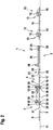
- the FIG. 1 shows a schematic representation of a portion of a fitting 1 for a window not shown here in detail 2, which is formed for example as a living room window.
- the fitting 1 has a drive rod 3 and an Axerstulpelement 4.
- the Axerstulpelement 4 has a guide device 5 for a Axerarm 6 not shown here or a guide element 7 of the Axerarms 6 on. It can be clearly seen that the drive rod 3 is multi-piece. It consists of a Axer Suite 8 and at least one connection region 9, in the embodiment shown here, two connection areas 9 and 10th
- connection areas 9 and 10 are arranged in the axial direction with respect to a longitudinal central axis 11 of the Axer Schemes 8 on opposite sides of the Axer Scheme 8 and connected thereto.
- the connection areas 9 and 10 can basically in any way and Way fixed to the Axer Scheme 8, in particular unsolvable, be.
- they are each riveted to the Axer Scheme 8, so that the attachment is realized in each case by means of at least one fastener 12.
- the attachment of the connection areas 9 and 10 to the Axer Scheme 8 is rigid and / or permanent.
- connection region 9 and / or the connection region 10 are each assigned a plurality of spaced-apart fastening elements 12, which are arranged offset to one another, for example, in the axial direction. In this way, tilting of the respective connection region 9 or 10 with respect to the axial region 8 is reliably prevented.
- connection region 9 is effected by means of a single fastening element 12, not shown, while the connection region 10 is fastened to the axial region 8 by means of a plurality of (here: two) fastening elements 12.
- At least one of the attachment of the connection portion 10 on the Axer Scheme 8 serving fasteners 12, preferably several or all of these fasteners 12, has a rear grip member 13 which can cooperate with a not shown Schugriffsumbleelement 14 to fix the Axerarm 6 in at least one direction ,
- the Schugriffsitchelement 14 is for example part of the Axerarms 6 or at least attached to this.
- the rear engagement counter-element 14 is riveted to the Axerarm 6 and / or caulked.
- the rear grip element 13 has two walls 15 directed away from the connection region 10, between which there is an insertion receptacle 16 for the rear engagement counter element 14.
- the rear grip element 13 and the rear grip counter element 14 are displaceable relative to one another in the axial direction in such a way that the rear grip counter element 14 is present in the insertion receptacle 16 in at least one position relative to one another and is prevented from displacing in the lateral direction by the opposing walls 15.
- the rear grip elements 13 are displaceable together with the drive rod 3 in the axial direction. For this purpose, they are correspondingly mounted on the window 2 or a frame 2 ', not shown, of the window 2.
- connection regions 9 and 10 are arranged in the axial direction at a distance from one another on the axial region 8 or connected thereto. And they are arranged offset perpendicular to the longitudinal central axis 11 to this. In particular, the connection regions 9 and 10 are respectively located on the axis region 8 and are arranged on the same side of the axial region 8.
- the Axerstulpelement 4 is at least partially on the Axer Scheme 8 of the drive rod 3 at. In this case, it is provided adjacent to the connection regions 9 and 10, in particular it is arranged in the axial direction between the two connection regions 9 and 10.
- the Axerstulpelement 4 has an Axer rail 17, which rests against the Axer Scheme 8.
- the axial rail 17 is aligned with the connection regions 9 and 10, so that, for example, their respective longitudinal central axes coincide.
- the guide device 5 On the Axer rail 17, the guide device 5 is arranged. In particular, the guide device 5 is located on the side of the axial rail 17 facing away from the axial region 8. Thus, while on the one hand the axle area 8 bears against the axle rail 17, the guide device 5 rests on the opposite side.
- the Axerstulpelement 4 is fixed by means of at least one holding element 18, in the embodiment shown here, two holding elements 18, at least in the axial direction with respect to the frame 2 'of the window.
- the holding element 18 engages in a passage opening 19 of the axle area 8, which is not recognizable here, or even passes through it - for fixing to the frame 2 '.
- each of the holding elements 18 is assigned a separate through-passage 19. Of course, however, several of the holding elements 18, in particular all holding elements 18, pass through the same through-passage recess 19, so that, for example, only a single through-passage 19 is formed in the axial area 8.
- connection areas 9 and 10 are used for connection, in particular for detachable connection, with a further drive rod, not shown, and / or a corner drive.
- the connection areas 9 and 10 each have a coupling device 20, which can only be seen here for the connection area 10.
- the coupling device 20 of the connection region 10 is in the form of a suspension opening 21, for example.
- the coupling device 20 of the connection region 9 is preferably in the form of a toothing, in particular an external toothing.
- another embodiment of the coupling devices 20 can be realized.
- a longitudinal guide opening 22 is formed, preferably slit-like, for example oblong-shaped, is.
- the longitudinal guide opening 22 is formed, for example, peripherally closed in the Axer rail 17.
- the longitudinal guide opening 22 is penetrated by a longitudinal guide element 23, which is fastened on the one hand to the drive rod 3 or its Axer Scheme 8 and on the other hand has a head 24 which rests on the side facing away from the Axer Scheme 8 side of the longitudinal guide opening 22 at an edge 25 of the longitudinal guide opening 22 slidably.
- the area of the longitudinal guide element 23 received by the longitudinal guide opening 22 preferably has smaller dimensions in the axial direction than the longitudinal guide opening 22, but in the lateral direction the same or at least substantially the same dimensions.
- auxiliary arm 26 for the Axerarm 6 is rotatably mounted on the Axerstulpelement 4 .
- a bearing pin 28 is disposed on the auxiliary arm 26 which is provided for receiving in a bearing opening of the Axerarms 6, not shown.
- the auxiliary arm 26 is spaced from the Axer rail 17 mounted thereon.
- a spacer 29 is arranged between the auxiliary arm 26 and the axle rail 17.
- the spacer 29 is preferably secured against rotation on the axle rail 17.
- the spacer 29 may have a retaining projection 30, which is not recognizable here, which engages in a corresponding, in particular edge-closed, recess of the axial rail 17.
- the spacer 29 is preferably made of a material which has better sliding properties than the auxiliary arm 26 and / or the axle rail 17 in order to ensure a simple pivoting of the auxiliary arm 26 with respect to the axial rail 17.
- the guide device 5 has a guide receptacle 31 for the Axerarm 6 or its guide element 7.
- the guide receptacle 31 is preferably formed peripherally closed in the circumferential direction in the guide device 5.
- the guide receptacle 31 may be at least partially closed on its side facing away from the Axer rail 17 with a cover 32.
- the guide receptacle 31 passes completely through the guide device 5 in one direction, in particular in the vertical direction.
- the means that the investigatingsaufhahme 31 extends up to the Axer rail 17 and a bottom or bottom of the guide receptacle 31 is formed by the Axer rail 17.
- FIG. 2 shows a longitudinal sectional view of a portion of the fitting 1, in particular the drive rod 3 and the Axerstulpelements 4. It can be clearly seen that the holding element 18 and the holding elements 18, the passage recess 19 at least partially pass through, so protrude into this. Shown are the holding elements 18 in a pre-assembly position in which they are present before assembly of the fitting 1 on the window 2 or the frame 2 'of the window 2. In this pre-assembly position they protrude on the side facing away from the axle rail 17 on the guide means 5 also, so are about this over. This prevents an arrangement of the Axerarms 6 or its guide element 7 on the guide means 5, in particular an introduction of the guide member 7 in the ceremoniessaufhahme 31st
- the holding elements 18 are displaced in the direction of the frame 2 ', so that the projection is reduced by the guide means 5 or eliminated altogether.
- an end of the holding elements 18 facing away from the frame 2 ' is completely received in the guide device 5 in a post-assembly position of the holding elements 18 which is present after assembly, ie is no longer over the guide device 5 on the side opposite the axial rail 7.
- the holding elements 18 are preferably designed as screws, in particular as punching screws. In the latter case, the holding elements 18 have a threaded portion 33 and a punching projection 34.
- a screw head 35 is provided, which has an internal polygonal tool receiving in the embodiment shown here. On the screw head 35 can be attacked by means of a tool to screw the punching screw 18 in the guide device 5 and in the direction of the frame 2 '.
- connection areas 9 and 10 as well as the axis rail 17 have the same thickness, ie they have identical dimensions in the vertical direction.
- connection regions 9 and 10 and the axial rail 17 are arranged in alignment, in particular in the lateral and / or vertical direction, so that particularly preferably their longitudinal central axes coincide and consequently the connection regions 9 and 10 and the axial rail 17 have a common longitudinal central axis.
- connection areas 9 and 10 and the Axer rail 17 have the same width, ie the same dimensions in the lateral direction.
- the Axer Scheme 8 of the drive rod 3 has a smaller width. In this case, it is preferably arranged centrally with respect to the connection regions 9 and 10 and the axial rail 17 in the lateral direction.
- the guide device 5 is fastened to the axle rail 17 by means of at least one connecting element 36 (here: two connecting elements 36). Particularly preferably, a positive connection is produced by means of the connecting element 36.
- the connecting element 36 is preferably embodied in one piece and / or with the same material as the guide device 5 and, to that extent, for example, is in the form of an extension from this.
- the connecting element 36 preferably fully penetrates the axial rail 17, in particular it is arranged in a passage opening 37 of the axial rail 17.
- the connecting element 36 is in the form of a rivet or the like, for example. For example, it is widened on the side facing away from the guide device 5 side of the axial rail 17 so that it has a positive connection region 38 there.
- the form-fit region preferably has larger dimensions at least in some regions than the passage opening 37, so that it engages behind the axial rail 17 on its side facing away from the guide device 5 and correspondingly reliably holds the guide device 5 positively on the axial rail 17.
- the connecting element 36 projects, in particular with its form-fit region 38, into the through-passage recess 19 of the axial region.
- FIG. 3 shows a detail sectional view of a portion of the fitting 1, wherein in addition to the elements described above, the Axerarm 6 and its guide element 7 are shown.
- the guide element 7 is designed as a guide pin, which has a rear grip collar 39 on its end facing away from the Axerarm 6. This is used, for example, for realizing a lift-off prevention for the arm 6.
- the guide device 5 and the guide element 7 are preferably designed such that the arm 6 can be removed from the guide device 5 in a first position shown here while being different in one from the first position cooperate second position to prevent lifting of the Axerarms 6 of the guide means 5.
- the guide device 5 is designed accordingly.
- the cover 32 may have a corresponding shape.
- the holding elements 18 are shown here in their pre-assembly. In this they protrude beyond the guide means 5 on its side facing away from the Axer rail 17 side. This means that the Axerarm 6 of the protruding support members 18 or at least one of the holding elements 18 spaced from the guide means 5 or is held in a first position, so that arranging the Axerarms 6 on the guide means 5, in particular arranging the guide member 7 in the Guide holder 31, not possible. A final assembly of the Axerarms 6 is therefore only possible if the holding elements 18 are arranged in their Nachmontagegna, so less or not at all beyond the guide means 5 on its side facing away from the Axer rail 17 side.
- FIG. 4 shows a further detailed sectional view of the area of the fitting 1, wherein the holding elements 18 are now present in a Nachmontagegna and are arranged such that the Axerarm 6 can be arranged on the guide means 5 at least partially adjacent or in a second position.
- the holding elements 18 are preferably arranged completely submerged in the guide device 5. They further preferably pass through the respective passage recess 19 completely in the direction of their respective longitudinal central axis, ie they engage in particular in a frame 2 'of the window 2, not shown here.
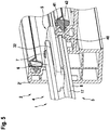
- the FIG. 5 shows a sectional view through an area of a window 2, in particular through the frame 2 'of the window 2, on which a part of the fitting 1 is arranged.
- the frame 2 ' has a fitting receptacle 40, which is formed as a groove in the frame 2'.
- At least one receiving groove 41 extends from the fitting receptacle 40, in particular two receiving grooves 41 on opposite sides of the fitting receptacle 40.
- the receptacle groove 41 passes through a side wall 42 of the fitting receptacle 40. If two opposite receptacle grooves 41 are provided, the two receptacle grooves 41 pass through opposite side walls 42 the fitting 40.
- the axial rail 17 in the Aufhahmenut 41 and the opposite grooves 41 engages. It is located there fixed.
- the Axer Scheme 8 of the drive rod 3 is also disposed in the fitting receptacle 40, but outside the Aufhahmenut 41. In particular, it is below the Axer rail 17 in the fitting receptacle 40, in particular on the guide means 5 opposite side of the Axer rail 17, provided in the fitting receptacle 40 ,
- the connection areas 9 and 10 are also present in the fitting receptacle 40. Analogous to the Axer rail 17, they engage in the Receiving groove 41 and in both opposite grooves 41 a. They are stored in this or in this relocatable.
- the Axer Scheme 18 is mounted displaceably in the fitting receptacle 40 in the axial direction. He may rest against the side wall 42 or at least one of the side walls 42, particularly preferably on opposite side walls 42, the fitting receptacle 40. In this way, a reliable longitudinal guidance of the Axer Schemes 8 of the drive rod 3 is achieved.
- the Axer rail 17 is fixed by means of the holding elements 18 with respect to the frame 2 'in the fitting receptacle 40.
- the holding elements 18 at least partially, for example, with their punching projections 34, engage in the frame 2 'a.
- FIG. 6 shows a further detailed sectional view of the window 2 and its frame 2 '.
- the connection region 10 is also present in the fitting receptacle 40 and thereby engages in the receiving groove 41 or in the opposite receiving grooves 41.
- the fastening elements 12 with the rear grip elements 13 provided thereon.
- the rear grip elements 13 are arranged such that the rear grip counter elements 14 of the axial arm 16 are present in the slot receptacles 16. Accordingly, pivoting of the Axerarms 6 is not possible in the illustrated position of the drive rod 3 and the connection portion 10.
- the rear grip elements 13 and the rear engagement counter-elements 14 can be designed to form a lifting prevention for the Axerarm 6. In this case, not only the pivoting, but also the lifting of the Axerarms 6 is prevented in the direction away from the drive rod 3 direction.
- the fitting 1 described here and a method for its production allow a simple and cost-effective implementation of the drive rod 3 as a stamped part.
- the individual components of the drive rod 3, namely the Axer Scheme 8 and the terminal portions 9 and 10 are each made as a stamped part separately from the other elements. They are preferably of uniform material, ie consist of the same material. Also, the Axerarm 6 and / or the Axerschiene 17 may be present as a stamped part. In addition, they are also preferably of the same material as the axler area 8 and / or the connection areas 9 and 10.
- the drive rod 3, so the Axer Scheme 8 and the terminal areas 9 and 10 on the one hand and the Axer rail 17 on the other hand made of metal, in particular made of steel or sheet steel.
Landscapes
- Engineering & Computer Science (AREA)
- Mechanical Engineering (AREA)
- Power-Operated Mechanisms For Wings (AREA)
- Window Of Vehicle (AREA)
Priority Applications (1)
| Application Number | Priority Date | Filing Date | Title |
|---|---|---|---|
| PL17167313T PL3235984T3 (pl) | 2016-04-23 | 2017-04-20 | Okucie dla okna, sposób wytwarzania okucia, jak też odpowiedniego okna |
Applications Claiming Priority (1)
| Application Number | Priority Date | Filing Date | Title |
|---|---|---|---|
| DE102016004915.4A DE102016004915B3 (de) | 2016-04-23 | 2016-04-23 | Beschlag für ein Fenster, Verfahren zum Herstellen des Beschlags sowie entsprechendes Fenster |
Publications (2)
| Publication Number | Publication Date |
|---|---|
| EP3235984A1 true EP3235984A1 (fr) | 2017-10-25 |
| EP3235984B1 EP3235984B1 (fr) | 2019-01-09 |
Family
ID=58632204
Family Applications (1)
| Application Number | Title | Priority Date | Filing Date |
|---|---|---|---|
| EP17167313.0A Not-in-force EP3235984B1 (fr) | 2016-04-23 | 2017-04-20 | Ferrure de fenêtre, son procédé de fabrication et fenêtre correspondante |
Country Status (4)
| Country | Link |
|---|---|
| EP (1) | EP3235984B1 (fr) |
| DE (1) | DE102016004915B3 (fr) |
| PL (1) | PL3235984T3 (fr) |
| TR (1) | TR201903396T4 (fr) |
Families Citing this family (1)
| Publication number | Priority date | Publication date | Assignee | Title |
|---|---|---|---|---|
| DE102018205282A1 (de) | 2018-04-09 | 2019-10-10 | Roto Frank Ag | Beschlagmontagesatz für Beschläge für eine Gebäudeverschlusseinrichtung sowie Verfahren zum Montieren eines Beschlags |
Citations (2)
| Publication number | Priority date | Publication date | Assignee | Title |
|---|---|---|---|---|
| DE19607366A1 (de) * | 1996-02-27 | 1997-08-28 | Winkhaus Fa August | Treibstangenbeschlag-Montagesatz |
| EP1067265A1 (fr) * | 1999-07-08 | 2001-01-10 | Aug. Winkhaus GmbH & Co. KG | Ensemble de ferrure pour fenêtre ou porte pivotante et basculante |
Family Cites Families (1)
| Publication number | Priority date | Publication date | Assignee | Title |
|---|---|---|---|---|
| DE2004855A1 (de) * | 1970-02-03 | 1971-09-23 | Fa. Aug. Winkhaus, 4404 Telgte | Fenster mit Drehkippbeschlag |
-
2016
- 2016-04-23 DE DE102016004915.4A patent/DE102016004915B3/de not_active Expired - Fee Related
-
2017
- 2017-04-20 EP EP17167313.0A patent/EP3235984B1/fr not_active Not-in-force
- 2017-04-20 TR TR2019/03396T patent/TR201903396T4/tr unknown
- 2017-04-20 PL PL17167313T patent/PL3235984T3/pl unknown
Patent Citations (2)
| Publication number | Priority date | Publication date | Assignee | Title |
|---|---|---|---|---|
| DE19607366A1 (de) * | 1996-02-27 | 1997-08-28 | Winkhaus Fa August | Treibstangenbeschlag-Montagesatz |
| EP1067265A1 (fr) * | 1999-07-08 | 2001-01-10 | Aug. Winkhaus GmbH & Co. KG | Ensemble de ferrure pour fenêtre ou porte pivotante et basculante |
Also Published As
| Publication number | Publication date |
|---|---|
| DE102016004915B3 (de) | 2017-10-19 |
| TR201903396T4 (tr) | 2019-04-22 |
| EP3235984B1 (fr) | 2019-01-09 |
| PL3235984T3 (pl) | 2019-07-31 |
Similar Documents
| Publication | Publication Date | Title |
|---|---|---|
| DE10361445B4 (de) | Kraftfahrzeugtürschloss | |
| EP2546438B1 (fr) | Dispositif prévu pour montage mobile dans une partie de ferrure prévue avec une gorge de ferrure dotée d'une contre-dépouille | |
| EP2252751B1 (fr) | Ferrure de tige d entraînement pour une fenêtre ou une porte | |
| EP3235984B1 (fr) | Ferrure de fenêtre, son procédé de fabrication et fenêtre correspondante | |
| EP2206860A2 (fr) | Armature dotée d'un élément de verrouillage démontable | |
| EP1863990B1 (fr) | Mecanisme de commande de bielle | |
| EP2947221B1 (fr) | Fenêtre de toit et procédé de montage d'une fenêtre de toit | |
| EP2373864B1 (fr) | Palier d'angle pour fenêtre ou porte pivotante ou basculante ou similaire | |
| EP3535824B1 (fr) | Support de jeu de barres et ensemble correspondant | |
| EP2317047B1 (fr) | Agencement de ferrure | |
| WO2000052288A1 (fr) | Fenetre ou porte | |
| DE102009033939B4 (de) | Wohndachfenster sowie Verfahren zum Befestigen eines Abdeckblechs | |
| EP2295684B1 (fr) | Butée pour une fenêtre, une porte ou analogue, ainsi que fenêtre, porte ou analogue dotée d'une telle butée | |
| EP3235988A1 (fr) | Système de fenêtre et/ou système de porte | |
| DE102014007699B3 (de) | Schwingscharnier für ein Fenster, insbesondere Wohndachfenster | |
| WO2013083265A1 (fr) | Elément de support pour un lève-glace pour véhicule automobile avec structure de renforcement | |
| DE69805042T2 (de) | Beschlag für Tür, Fenster oder ähnliches, insbesondere ein Schliessblech, Scharnierlagerung oder dergleichen | |
| DE4029694A1 (de) | Griff fuer eine kraftfahrzeugtuer | |
| WO2008068304A2 (fr) | Crémone | |
| EP0556442A1 (fr) | Ferrure de tringle de commande pour portes, fenêtres et similaires | |
| EP3018269B1 (fr) | Systeme de poignee pour une fenetre ou similaire et fenetre ou similaire dotee du systeme de poignee | |
| EP1091065A2 (fr) | Elément de verrouillage pour une ferrure de verrouillage d'un vantail mobile d'une fenêtre ou d'une porte | |
| DE19734647B4 (de) | Beschlagteil an einem Flügel oder einem festen Rahmen eines Fensters, einer Tür od. dgl. | |
| EP1361327B1 (fr) | Ferrure | |
| EP3095938A1 (fr) | Armature et procede de fabrication d'une armature |
Legal Events
| Date | Code | Title | Description |
|---|---|---|---|
| PUAI | Public reference made under article 153(3) epc to a published international application that has entered the european phase |
Free format text: ORIGINAL CODE: 0009012 |
|
| STAA | Information on the status of an ep patent application or granted ep patent |
Free format text: STATUS: THE APPLICATION HAS BEEN PUBLISHED |
|
| AK | Designated contracting states |
Kind code of ref document: A1 Designated state(s): AL AT BE BG CH CY CZ DE DK EE ES FI FR GB GR HR HU IE IS IT LI LT LU LV MC MK MT NL NO PL PT RO RS SE SI SK SM TR |
|
| AX | Request for extension of the european patent |
Extension state: BA ME |
|
| STAA | Information on the status of an ep patent application or granted ep patent |
Free format text: STATUS: REQUEST FOR EXAMINATION WAS MADE |
|
| 17P | Request for examination filed |
Effective date: 20180208 |
|
| RBV | Designated contracting states (corrected) |
Designated state(s): AL AT BE BG CH CY CZ DE DK EE ES FI FR GB GR HR HU IE IS IT LI LT LU LV MC MK MT NL NO PL PT RO RS SE SI SK SM TR |
|
| GRAP | Despatch of communication of intention to grant a patent |
Free format text: ORIGINAL CODE: EPIDOSNIGR1 |
|
| STAA | Information on the status of an ep patent application or granted ep patent |
Free format text: STATUS: GRANT OF PATENT IS INTENDED |
|
| INTG | Intention to grant announced |
Effective date: 20180717 |
|
| GRAJ | Information related to disapproval of communication of intention to grant by the applicant or resumption of examination proceedings by the epo deleted |
Free format text: ORIGINAL CODE: EPIDOSDIGR1 |
|
| STAA | Information on the status of an ep patent application or granted ep patent |
Free format text: STATUS: REQUEST FOR EXAMINATION WAS MADE |
|
| GRAR | Information related to intention to grant a patent recorded |
Free format text: ORIGINAL CODE: EPIDOSNIGR71 |
|
| GRAS | Grant fee paid |
Free format text: ORIGINAL CODE: EPIDOSNIGR3 |
|
| STAA | Information on the status of an ep patent application or granted ep patent |
Free format text: STATUS: GRANT OF PATENT IS INTENDED |
|
| GRAA | (expected) grant |
Free format text: ORIGINAL CODE: 0009210 |
|
| STAA | Information on the status of an ep patent application or granted ep patent |
Free format text: STATUS: THE PATENT HAS BEEN GRANTED |
|
| INTC | Intention to grant announced (deleted) | ||
| AK | Designated contracting states |
Kind code of ref document: B1 Designated state(s): AL AT BE BG CH CY CZ DE DK EE ES FI FR GB GR HR HU IE IS IT LI LT LU LV MC MK MT NL NO PL PT RO RS SE SI SK SM TR |
|
| INTG | Intention to grant announced |
Effective date: 20181203 |
|
| REG | Reference to a national code |
Ref country code: GB Ref legal event code: FG4D Free format text: NOT ENGLISH |
|
| REG | Reference to a national code |
Ref country code: CH Ref legal event code: EP Ref country code: AT Ref legal event code: REF Ref document number: 1087506 Country of ref document: AT Kind code of ref document: T Effective date: 20190115 |
|
| REG | Reference to a national code |
Ref country code: DE Ref legal event code: R096 Ref document number: 502017000638 Country of ref document: DE |
|
| REG | Reference to a national code |
Ref country code: IE Ref legal event code: FG4D Free format text: LANGUAGE OF EP DOCUMENT: GERMAN |
|
| REG | Reference to a national code |
Ref country code: NL Ref legal event code: MP Effective date: 20190109 |
|
| REG | Reference to a national code |
Ref country code: LT Ref legal event code: MG4D |
|
| PG25 | Lapsed in a contracting state [announced via postgrant information from national office to epo] |
Ref country code: NL Free format text: LAPSE BECAUSE OF FAILURE TO SUBMIT A TRANSLATION OF THE DESCRIPTION OR TO PAY THE FEE WITHIN THE PRESCRIBED TIME-LIMIT Effective date: 20190109 |
|
| PG25 | Lapsed in a contracting state [announced via postgrant information from national office to epo] |
Ref country code: LT Free format text: LAPSE BECAUSE OF FAILURE TO SUBMIT A TRANSLATION OF THE DESCRIPTION OR TO PAY THE FEE WITHIN THE PRESCRIBED TIME-LIMIT Effective date: 20190109 Ref country code: FI Free format text: LAPSE BECAUSE OF FAILURE TO SUBMIT A TRANSLATION OF THE DESCRIPTION OR TO PAY THE FEE WITHIN THE PRESCRIBED TIME-LIMIT Effective date: 20190109 Ref country code: ES Free format text: LAPSE BECAUSE OF FAILURE TO SUBMIT A TRANSLATION OF THE DESCRIPTION OR TO PAY THE FEE WITHIN THE PRESCRIBED TIME-LIMIT Effective date: 20190109 Ref country code: NO Free format text: LAPSE BECAUSE OF FAILURE TO SUBMIT A TRANSLATION OF THE DESCRIPTION OR TO PAY THE FEE WITHIN THE PRESCRIBED TIME-LIMIT Effective date: 20190409 Ref country code: PT Free format text: LAPSE BECAUSE OF FAILURE TO SUBMIT A TRANSLATION OF THE DESCRIPTION OR TO PAY THE FEE WITHIN THE PRESCRIBED TIME-LIMIT Effective date: 20190509 Ref country code: SE Free format text: LAPSE BECAUSE OF FAILURE TO SUBMIT A TRANSLATION OF THE DESCRIPTION OR TO PAY THE FEE WITHIN THE PRESCRIBED TIME-LIMIT Effective date: 20190109 |
|
| PGFP | Annual fee paid to national office [announced via postgrant information from national office to epo] |
Ref country code: DE Payment date: 20190420 Year of fee payment: 3 Ref country code: PL Payment date: 20190419 Year of fee payment: 3 |
|
| PG25 | Lapsed in a contracting state [announced via postgrant information from national office to epo] |
Ref country code: GR Free format text: LAPSE BECAUSE OF FAILURE TO SUBMIT A TRANSLATION OF THE DESCRIPTION OR TO PAY THE FEE WITHIN THE PRESCRIBED TIME-LIMIT Effective date: 20190410 Ref country code: BG Free format text: LAPSE BECAUSE OF FAILURE TO SUBMIT A TRANSLATION OF THE DESCRIPTION OR TO PAY THE FEE WITHIN THE PRESCRIBED TIME-LIMIT Effective date: 20190409 Ref country code: RS Free format text: LAPSE BECAUSE OF FAILURE TO SUBMIT A TRANSLATION OF THE DESCRIPTION OR TO PAY THE FEE WITHIN THE PRESCRIBED TIME-LIMIT Effective date: 20190109 Ref country code: LV Free format text: LAPSE BECAUSE OF FAILURE TO SUBMIT A TRANSLATION OF THE DESCRIPTION OR TO PAY THE FEE WITHIN THE PRESCRIBED TIME-LIMIT Effective date: 20190109 Ref country code: IS Free format text: LAPSE BECAUSE OF FAILURE TO SUBMIT A TRANSLATION OF THE DESCRIPTION OR TO PAY THE FEE WITHIN THE PRESCRIBED TIME-LIMIT Effective date: 20190509 Ref country code: HR Free format text: LAPSE BECAUSE OF FAILURE TO SUBMIT A TRANSLATION OF THE DESCRIPTION OR TO PAY THE FEE WITHIN THE PRESCRIBED TIME-LIMIT Effective date: 20190109 |
|
| PGFP | Annual fee paid to national office [announced via postgrant information from national office to epo] |
Ref country code: FR Payment date: 20190418 Year of fee payment: 3 Ref country code: TR Payment date: 20190415 Year of fee payment: 3 |
|
| REG | Reference to a national code |
Ref country code: DE Ref legal event code: R097 Ref document number: 502017000638 Country of ref document: DE |
|
| PG25 | Lapsed in a contracting state [announced via postgrant information from national office to epo] |
Ref country code: AL Free format text: LAPSE BECAUSE OF FAILURE TO SUBMIT A TRANSLATION OF THE DESCRIPTION OR TO PAY THE FEE WITHIN THE PRESCRIBED TIME-LIMIT Effective date: 20190109 Ref country code: DK Free format text: LAPSE BECAUSE OF FAILURE TO SUBMIT A TRANSLATION OF THE DESCRIPTION OR TO PAY THE FEE WITHIN THE PRESCRIBED TIME-LIMIT Effective date: 20190109 Ref country code: IT Free format text: LAPSE BECAUSE OF FAILURE TO SUBMIT A TRANSLATION OF THE DESCRIPTION OR TO PAY THE FEE WITHIN THE PRESCRIBED TIME-LIMIT Effective date: 20190109 Ref country code: EE Free format text: LAPSE BECAUSE OF FAILURE TO SUBMIT A TRANSLATION OF THE DESCRIPTION OR TO PAY THE FEE WITHIN THE PRESCRIBED TIME-LIMIT Effective date: 20190109 Ref country code: SK Free format text: LAPSE BECAUSE OF FAILURE TO SUBMIT A TRANSLATION OF THE DESCRIPTION OR TO PAY THE FEE WITHIN THE PRESCRIBED TIME-LIMIT Effective date: 20190109 Ref country code: CZ Free format text: LAPSE BECAUSE OF FAILURE TO SUBMIT A TRANSLATION OF THE DESCRIPTION OR TO PAY THE FEE WITHIN THE PRESCRIBED TIME-LIMIT Effective date: 20190109 Ref country code: RO Free format text: LAPSE BECAUSE OF FAILURE TO SUBMIT A TRANSLATION OF THE DESCRIPTION OR TO PAY THE FEE WITHIN THE PRESCRIBED TIME-LIMIT Effective date: 20190109 |
|
| PLBE | No opposition filed within time limit |
Free format text: ORIGINAL CODE: 0009261 |
|
| STAA | Information on the status of an ep patent application or granted ep patent |
Free format text: STATUS: NO OPPOSITION FILED WITHIN TIME LIMIT |
|
| 26N | No opposition filed |
Effective date: 20191010 |
|
| REG | Reference to a national code |
Ref country code: BE Ref legal event code: MM Effective date: 20190430 |
|
| PG25 | Lapsed in a contracting state [announced via postgrant information from national office to epo] |
Ref country code: MC Free format text: LAPSE BECAUSE OF FAILURE TO SUBMIT A TRANSLATION OF THE DESCRIPTION OR TO PAY THE FEE WITHIN THE PRESCRIBED TIME-LIMIT Effective date: 20190109 Ref country code: LU Free format text: LAPSE BECAUSE OF NON-PAYMENT OF DUE FEES Effective date: 20190420 |
|
| PG25 | Lapsed in a contracting state [announced via postgrant information from national office to epo] |
Ref country code: BE Free format text: LAPSE BECAUSE OF NON-PAYMENT OF DUE FEES Effective date: 20190430 Ref country code: SI Free format text: LAPSE BECAUSE OF FAILURE TO SUBMIT A TRANSLATION OF THE DESCRIPTION OR TO PAY THE FEE WITHIN THE PRESCRIBED TIME-LIMIT Effective date: 20190109 |
|
| PG25 | Lapsed in a contracting state [announced via postgrant information from national office to epo] |
Ref country code: IE Free format text: LAPSE BECAUSE OF NON-PAYMENT OF DUE FEES Effective date: 20190420 |
|
| REG | Reference to a national code |
Ref country code: DE Ref legal event code: R119 Ref document number: 502017000638 Country of ref document: DE |
|
| REG | Reference to a national code |
Ref country code: CH Ref legal event code: PL |
|
| PG25 | Lapsed in a contracting state [announced via postgrant information from national office to epo] |
Ref country code: LI Free format text: LAPSE BECAUSE OF NON-PAYMENT OF DUE FEES Effective date: 20200430 Ref country code: DE Free format text: LAPSE BECAUSE OF NON-PAYMENT OF DUE FEES Effective date: 20201103 Ref country code: CH Free format text: LAPSE BECAUSE OF NON-PAYMENT OF DUE FEES Effective date: 20200430 Ref country code: FR Free format text: LAPSE BECAUSE OF NON-PAYMENT OF DUE FEES Effective date: 20200430 |
|
| PG25 | Lapsed in a contracting state [announced via postgrant information from national office to epo] |
Ref country code: CY Free format text: LAPSE BECAUSE OF FAILURE TO SUBMIT A TRANSLATION OF THE DESCRIPTION OR TO PAY THE FEE WITHIN THE PRESCRIBED TIME-LIMIT Effective date: 20190109 |
|
| PG25 | Lapsed in a contracting state [announced via postgrant information from national office to epo] |
Ref country code: SM Free format text: LAPSE BECAUSE OF FAILURE TO SUBMIT A TRANSLATION OF THE DESCRIPTION OR TO PAY THE FEE WITHIN THE PRESCRIBED TIME-LIMIT Effective date: 20190109 |
|
| PG25 | Lapsed in a contracting state [announced via postgrant information from national office to epo] |
Ref country code: HU Free format text: LAPSE BECAUSE OF FAILURE TO SUBMIT A TRANSLATION OF THE DESCRIPTION OR TO PAY THE FEE WITHIN THE PRESCRIBED TIME-LIMIT; INVALID AB INITIO Effective date: 20170420 Ref country code: MT Free format text: LAPSE BECAUSE OF FAILURE TO SUBMIT A TRANSLATION OF THE DESCRIPTION OR TO PAY THE FEE WITHIN THE PRESCRIBED TIME-LIMIT Effective date: 20190109 |
|
| GBPC | Gb: european patent ceased through non-payment of renewal fee |
Effective date: 20210420 |
|
| PG25 | Lapsed in a contracting state [announced via postgrant information from national office to epo] |
Ref country code: GB Free format text: LAPSE BECAUSE OF NON-PAYMENT OF DUE FEES Effective date: 20210420 |
|
| PG25 | Lapsed in a contracting state [announced via postgrant information from national office to epo] |
Ref country code: TR Free format text: LAPSE BECAUSE OF NON-PAYMENT OF DUE FEES Effective date: 20200420 Ref country code: MK Free format text: LAPSE BECAUSE OF FAILURE TO SUBMIT A TRANSLATION OF THE DESCRIPTION OR TO PAY THE FEE WITHIN THE PRESCRIBED TIME-LIMIT Effective date: 20190109 |
|
| PG25 | Lapsed in a contracting state [announced via postgrant information from national office to epo] |
Ref country code: PL Free format text: LAPSE BECAUSE OF NON-PAYMENT OF DUE FEES Effective date: 20200420 |
|
| REG | Reference to a national code |
Ref country code: AT Ref legal event code: MM01 Ref document number: 1087506 Country of ref document: AT Kind code of ref document: T Effective date: 20220420 |
|
| PG25 | Lapsed in a contracting state [announced via postgrant information from national office to epo] |
Ref country code: AT Free format text: LAPSE BECAUSE OF NON-PAYMENT OF DUE FEES Effective date: 20220420 |