EP3235657A1 - Wärmeisoliertes rad - Google Patents
Wärmeisoliertes rad Download PDFInfo
- Publication number
- EP3235657A1 EP3235657A1 EP17160560.3A EP17160560A EP3235657A1 EP 3235657 A1 EP3235657 A1 EP 3235657A1 EP 17160560 A EP17160560 A EP 17160560A EP 3235657 A1 EP3235657 A1 EP 3235657A1
- Authority
- EP
- European Patent Office
- Prior art keywords
- wheel
- heat insulator
- outer diameter
- diameter surface
- various embodiments
- Prior art date
- Legal status (The legal status is an assumption and is not a legal conclusion. Google has not performed a legal analysis and makes no representation as to the accuracy of the status listed.)
- Withdrawn
Links
Images


Classifications
-
- B—PERFORMING OPERATIONS; TRANSPORTING
- B60—VEHICLES IN GENERAL
- B60B—VEHICLE WHEELS; CASTORS; AXLES FOR WHEELS OR CASTORS; INCREASING WHEEL ADHESION
- B60B3/00—Disc wheels, i.e. wheels with load-supporting disc body
- B60B3/02—Disc wheels, i.e. wheels with load-supporting disc body with a single disc body integral with rim
-
- B—PERFORMING OPERATIONS; TRANSPORTING
- B64—AIRCRAFT; AVIATION; COSMONAUTICS
- B64C—AEROPLANES; HELICOPTERS
- B64C25/00—Alighting gear
- B64C25/32—Alighting gear characterised by elements which contact the ground or similar surface
- B64C25/34—Alighting gear characterised by elements which contact the ground or similar surface wheeled type, e.g. multi-wheeled bogies
- B64C25/36—Arrangements or adaptations of wheels, tyres or axles in general
-
- B—PERFORMING OPERATIONS; TRANSPORTING
- B60—VEHICLES IN GENERAL
- B60B—VEHICLE WHEELS; CASTORS; AXLES FOR WHEELS OR CASTORS; INCREASING WHEEL ADHESION
- B60B21/00—Rims
- B60B21/12—Appurtenances, e.g. lining bands
-
- B—PERFORMING OPERATIONS; TRANSPORTING
- B64—AIRCRAFT; AVIATION; COSMONAUTICS
- B64C—AEROPLANES; HELICOPTERS
- B64C25/00—Alighting gear
- B64C25/32—Alighting gear characterised by elements which contact the ground or similar surface
- B64C25/42—Arrangement or adaptation of brakes
-
- B—PERFORMING OPERATIONS; TRANSPORTING
- B60—VEHICLES IN GENERAL
- B60B—VEHICLE WHEELS; CASTORS; AXLES FOR WHEELS OR CASTORS; INCREASING WHEEL ADHESION
- B60B2360/00—Materials; Physical forms thereof
- B60B2360/30—Synthetic materials
- B60B2360/34—Reinforced plastics
- B60B2360/341—Reinforced plastics with fibres
- B60B2360/3416—Carbone fibres
-
- B—PERFORMING OPERATIONS; TRANSPORTING
- B60—VEHICLES IN GENERAL
- B60B—VEHICLE WHEELS; CASTORS; AXLES FOR WHEELS OR CASTORS; INCREASING WHEEL ADHESION
- B60B2360/00—Materials; Physical forms thereof
- B60B2360/30—Synthetic materials
- B60B2360/34—Reinforced plastics
- B60B2360/344—With woven material
-
- B—PERFORMING OPERATIONS; TRANSPORTING
- B60—VEHICLES IN GENERAL
- B60B—VEHICLE WHEELS; CASTORS; AXLES FOR WHEELS OR CASTORS; INCREASING WHEEL ADHESION
- B60B2360/00—Materials; Physical forms thereof
- B60B2360/30—Synthetic materials
- B60B2360/36—Composite materials
-
- B—PERFORMING OPERATIONS; TRANSPORTING
- B60—VEHICLES IN GENERAL
- B60B—VEHICLE WHEELS; CASTORS; AXLES FOR WHEELS OR CASTORS; INCREASING WHEEL ADHESION
- B60B2900/00—Purpose of invention
- B60B2900/20—Avoidance of
- B60B2900/212—Damage
Definitions
- the present disclosure relates generally to heat-insulated wheels.
- the friction between rotors and stators of a brake system in a wheel assembly create heat which may spread throughout the wheel and into the tire cavity.
- the tire cavity may comprise compressed nitrogen gas.
- the nitrogen gas being heated by heat created by the rotors and stators may increase the tire pressure, and in some cases, could cause a tire explosion. Therefore, it would be beneficial to insulate the nitrogen gas within the tire cavity from heat created by the rotors and stators of the wheel brake system.
- a wheel may comprise a wheel body comprising an outer diameter surface, an inner rim on an inboard side of the wheel body, an outer rim on an outboard side of the wheel body opposite the inner rim, and/or a heat insulator coupled to the outer diameter surface between the inner rim and the outer rim.
- the wheel may comprise a recess disposed in the outer diameter surface. The heat insulator may be disposed within the recess.
- the heat insulator may comprise a mineral fiber, such as stone wool.
- the heat insulator may comprise a high temperature insulation wool, such as alkaline earth silicate wool and/or alumino silicate wool.
- the heat insulator may comprise carbon fiber and/or asbestos.
- a wheel assembly may comprise a wheel body comprising an outer diameter surface, an inner rim on an inboard side of the wheel body, an outer rim on an outboard side of the wheel body opposite the inner rim, a heat insulator coupled to the outer diameter surface, and/or a tire comprising a tire perimeter and a tire cavity.
- the tire may be disposed circumferentially around the wheel body between the inner rim and the outer rim, wherein the tire cavity may be defined by the tire perimeter and the outer diameter surface.
- the heat insulator may disposed between the outer diameter surface and the tire cavity.
- the wheel body may comprise an inboard wheel half and an outboard wheel half.
- a recess may be disposed in the outer diameter surface.
- the heat insulator may be disposed within the recess.
- the heat insulator may comprise a mineral fiber, such as stone wool, and/or a high temperature insulation wool, such as alkaline earth silicate wool and/or alumino silicate wool.
- the heat insulator may comprise carbon fiber and/or asbestos.
- the wheel assembly may comprise an insulator fastening device disposed circumferentially around the wheel body between the tire cavity and the heat insulator, wherein the insulator fastening device may be coupled to the heat insulator.
- a method of assembling a wheel may comprise providing a wheel, comprising a wheel body and an outer diameter surface, and disposing a heat insulator circumferentially onto the outer diameter surface of the wheel.
- the method may comprise coupling an outboard wheel half to an inboard wheel half to form the wheel body.
- the method may comprise coupling an insulator fastening device circumferentially around the heat insulator.
- the heat insulator may comprise a mineral fiber, a high temperature insulation wool, carbon fiber, and/or asbestos.
- systems and methods may find particular use in connection with aircraft wheels and wheel assemblies.
- various aspects of the disclosed embodiments may be adapted for optimized performance with a variety of wheels and wheel assemblies.
- numerous applications of the present disclosure may be realized.
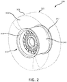
- the wheel assembly may comprise a wheel 10, a tire 20, and a disk brake assembly 38.
- Disk brake assembly 38 may comprise friction disks, which, during braking, are pressed against one another to slow the wheel, and in doing so create a large amount of heat (e.g., causing brake components' temperatures to rise to 1100°F (593°C) or higher).
- Wheel 10 may comprise an outer rim 18 and an inner rim 17.
- a tire 20 may be disposed between outer rim 18 and inner rim 17.
- Tire 20 may comprise a tire perimeter 22 which encloses a tire cavity 24 between tire perimeter 22 and wheel 10.
- Tire cavity 24 may comprise compressed nitrogen gas, or any other suitable gas.
- the temperature distribution within the wheel assembly is shown during wheel and brake system operation, wherein the temperature is highest within disk brake assembly 38, at a temperature about 1100°F (593°C). Heat may travel from disk brake assembly 38 into wheel 10 and/or tire cavity 24, with components of wheel 10 and tire 20 closer to disk brake assembly 38 having greater temperatures.
- tire cavity 24 may reach temperatures of about 400°F (204°C) and above. As used in this context only, "about” means plus or minus 100°F (54°C). Increased temperature within tire cavity 24 may cause an increase in the pressure of the nitrogen gas within tire cavity 24. Such an increased temperature and pressure within tire cavity 24 may result in undesirable events, such as a tire explosion.
- a wheel assembly 300 may comprise a wheel 310, a tire 320, and/or a heat insulator 340 coupled to wheel 310.
- Tire 320 may comprise tire perimeter 322 and/or a tire cavity 324.
- Tire cavity 324 may comprise compressed nitrogen gas or any other suitable gas.
- Wheel 310 may comprise an outer rim 318 and an inner rim 317, between which tire 320 is disposed.
- a heat insulator 340 may be coupled circumferentially to wheel 310 between outer rim 318 and inner rim 317.
- heat insulator 340 may be configured to decrease a heat transfer from disk brake assembly 38 to tire cavity 324 during braking so as to prevent, or allow less of, the heat created by disk brake assembly 38 from traveling into tire cavity 324.
- FIG. 3 illustrates a cross sectional view of wheel assembly 300, in accordance with various embodiments.
- the various components of wheel assembly 300 may be circumferentially disposed about axis of rotation 150.
- wheel 310 may comprise a wheel body 311.
- Wheel body 311 may comprise an inboard side 312 and an outboard side 314.
- Inner rim 317 may be disposed on inboard side 312 of wheel body 311 and outer rim 318 may be disposed on outboard side 314 of wheel body 311.
- wheel body 311 may comprise an outer diameter surface 330 between inner rim 317 and outer rim 318.
- Outer diameter surface 330 may be the radially outward-most surface of wheel body 311 from axis of rotation 150.
- heat insulator 340 may be coupled to outer diameter surface 330 between inner rim 317 and outer rim 318.
- heat insulator 340 may span the entire length of outer diameter surface 330.
- heat insulator 340 may span only a portion of outer diameter surface 330.
- Heat insulator 340 may be disposed on any portion of outer diameter surface 330, such as in the center of outer diameter surface 330 or any distance toward inner rim 317 or outer rim 318 along outer diameter surface 330.
- heat insulator 340 may have a uniform thickness across outer diameter surface 330.
- heat insulator 340 may be thicker (thickness, or thinness, being the radial length of heat insulator 340 measured substantially perpendicular to axis of rotation 150) toward the center of outer diameter surface 330 and may gradually get thinner (i.e., decreasing the radial length of heat insulator 340) toward inner rim 317 and/or outer rim 318.
- heat insulator 340 may be thicker toward inner rim 317 and may gradually get thinner toward outer rim 318, and/or heat insulator 340 may be thicker toward outer rim 318 and may gradually get thinner toward inner rim 317. In various embodiments, heat insulator 340 may be thicker toward inner rim 317 and outer rim 318 and may gradually get thinner toward the center of outer diameter surface 330.
- outer diameter surface 330 may comprise a recess 326.
- Heat insulator 340 may be disposed within recess 326.
- Recess 326 may be of a shape complementary to heat insulator 340, and heat insulator and recess 326 may be any suitable shape. Similar to the placement, shape and/or thickness of heat insulator 340, recess 326 may be disposed anywhere along outer diameter surface 330. For example, recess 326 may be disposed in the center 331 of outer diameter surface 330 or any distance toward inner rim 317 and/or outer rim 318 (i.e., any axial position along outer diameter surface 330 parallel to axis of rotation 150).
- recess 326 may have a uniform depth across outer diameter surface 330.
- recess 326 may be deeper (depth, or shallowness, being the radial length of recess 326 measured substantially perpendicular to axis of rotation 150) toward the center of outer diameter surface 330 and shallower toward inner rim 317 and/or outer rim 318.
- recess 326 may be deeper toward inner rim 317 and may gradually get shallower toward outer rim 318, and/or recess 326 may be deeper toward outer rim 318 and may gradually get shallower toward inner rim 317.
- recess 326 may be deeper toward inner rim 317 and outer rim 318 and may gradually get shallower toward the center of outer diameter surface 330.
- heat insulator 340 may be comprised of any suitable material, for example, a material having low thermal conductivity, low infrared radiation transparency, high resistance to high temperatures, low weight, and/or ease in handling.
- heat insulator 340 may be comprised of a mineral fiber, for example, stone wool, glass wool, and/or slag wool.
- heat insulator 340 may be comprised of a high temperature insulation wool, for example, alkaline earth silicate wool, alumino silicate wool, and/or polycrystalline wool.
- heat insulator 340 may be comprised of carbon fiber and/or asbestos.
- heat insulator 340 may comprise two or more materials, including, but not limited to, any of the materials discussed herein.
- heat insulator 340 may comprise multiple layers of one or more materials.
- heat insulator 340 may be coupled to wheel 310 in any suitable manner.
- heat insulator 340 may be coupled to wheel 310 by welding, riveting, nailing, screwing, an adhesive, the tension of heat insulator 340 around wheel 310, and/or in any other suitable manner.
- wheel assembly 300 may comprise a fuse plug 308 spanning from tire cavity 324 through wheel body 311 to a radially-inward part of wheel 310.
- Fuse plug 308 may be configured to melt in response to wheel body 311 reaching a certain temperature.
- compressed gas in tire cavity 324 may be able to escape through fuse plug 308 to avoid creating pressure under such a temperature that may cause a tire explosion.
- heat insulator 340 would comprise a hole radially outward of, and in line with, fuse plug 308, which may allow compressed gas to leave tire cavity 324 in case of excess pressure within tire cavity 324.
- a wheel assembly 500 may comprise a heat insulator 540 comprising one or more parts.
- heat insulator 540 may be split into two pieces, which may comprise an inner heat insulator 542 and/or an outer heat insulator 544.
- a heat insulator may be split into any number of parts, and each part may comprise the same or different material(s) as other parts, or the heat insulator, such as heat insulator 340 in FIG. 3 may be one piece of material.
- wheel assembly 500 may comprise an insulator fastening device 560 which may be coupled to heat insulator 540 circumferentially around wheel 310.
- Insulator fastening device 560 may be a solid piece of material, or may be a material comprising a net configuration, having voids in the material making up insulator fastening device 560.
- Insulator fastening device 560 may be configured to secure heat insulator 540 to wheel 310 and/or protect heat insulator 540.
- insulator fastening device 560 may be a solid ring and/or loop of material that is slid over heat insulator 540. Stated another way, insulator fastening device 560 may be a continuous loop without ends. In various embodiments, insulator fastening device 560 may be coupled to the wheel 310 and/or the heat insulator by wrapping insulator fastening device 560 around wheel 310 and/or the heat insulator.
- insulator fastening device 560 may comprise a fastening first end 566 which may be wrapped in direction 551 and a fastening second end 568 which may be wrapped in direction 552. Fastening first end 566 and fastening second end 568 may meet, overlap one another, and/or not meet when insulator fastening device 560 is wrapped around wheel 310.
- fastening first end 566 may be coupled to fastening second end 568 in any suitable manner.
- fastening first end 566 and fastening second end 568 may be coupled by being hooked, linked, nailed, screwed, adhered, and/or the like.
- insulator fastening device 560 may be coupled to the heat insulator in any suitable manner such as being nailed, screwed, adhered to the heat insulator, and/or the like.
- FIGS. 5A and 5B FIG. 5A depicts a top view of the ends of an insulator fastening device, and FIG. 5B depicts a side view of the ends of an insulator fastening device.
- fastening first end 566 may comprise a first hook 567
- fastening second end 568 may comprise a second hook 569
- First hook 567 may comprise a shape that is complementary to second hook 569 so first hook 567 may receive second hook 569 to couple fastening first end 566 to fastening second end 568.
- Second hook 569 may comprise any suitable shape and first hook 567 may be any shape complementary to second hook 569.
- fastening second end 568 may comprise any structure which may be coupled to a structure comprised on fastening first end 566.
- fastening first end 566 may be coupled to fastening second end 568 in any suitable manner, such as by the hooked manner depicted in FIGS. 5A and 5B .
- insulator fastening device 560 may be tightened from position 570 to position 571, and ends 546, of the heat insulator and/or the insulator fastening device, may be closer together in an embodiment in which the heat insulator is a piece of material comprising ends to better secure insulator fastening device 560 to heat insulator 540, and to better secure heat insulator 540 to the wheel.
- the heat insulator may be one continuous piece of material, and therefore, may not have ends 546. Insulator fastening device 560 may nevertheless be tightened from position 570 to position 571 to bring fastening first end 566 closer to fastening second end 568, to better secure the heat insulator to the wheel.
- insulator fastening device 560 may be comprised of any suitable material such as mineral rope.
- Mineral rope may be comprised of, for example, carbon fibers, asbestos fibers, and/or any other suitable material that is resistant to high temperature (e.g., 1100°F (593°C) and above).
- insulator fastening device 560 may be comprised of metal(s) and/or metal alloy(s) such as steel. Insulator fastening device 560 may be comprised of any number and/or combination of materials including, but not limited to, the materials discussed herein.
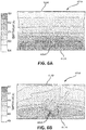
- interface 631A between an outer diameter surface and a tire cavity of a wheel assembly and interface 631B between a heat insulator and a tire cavity of a wheel, respectively, are depicted showing the temperature distributions for each.
- Interface 631A of FIG. 6A may be comprised in a wheel assembly that does not comprise a heat insulator coupled to the outer diameter surface of the wheel.
- heat may be passed from the brake assembly to the tire cavity uninhibited by a heat insulator, resulting in a large temperature gradient (e.g., temperatures at interface 631A between 628 Kelvin (671°F, 355°C) and 524 Kelvin (484°F, 251°C)) and an unequal temperature distribution (inboard side 612A being much hotter than outboard side 614A, a difference of about 88 Kelvin (159°F, 88°C).
- the hottest area 605A at interface 631A has a temperature of 628 Kelvin (671°F, 355°C), which may be a significant area of interface 631A.
- 6B may be in a wheel assembly comprising a heat insulator coupled to the outer diameter surface of the wheel. In such a case, during brake operation, heat may be transferred from the brake assembly to 631B to the tire cavity.
- the temperature gradient at interface 631B may be less than that at interface 631A (e.g., temperatures at interface 631B between 547 Kelvin (525°F, 274°C) and 469 Kelvin (385°F, 169°C)), and interface 631B may comprise a more equal temperature distribution (the temperatures of inboard side 612B and outboard side 614B are closer than those at interface 631A, e.g., a difference of about 22 Kelvin (38°F, 22°C).
- FIGS. 6A and 6B demonstrate the efficacy of a heat insulator in a wheel assembly.
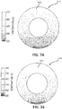
- FIGS. 7A and 7B depict cross sectional views of tire cavities 724A and 724B, respectively, filled with nitrogen gas.
- FIG. 7A depicts a tire cavity 724A comprised in a wheel assembly without a heat insulator coupled to the wheel.
- FIG. 7B depicts a tire cavity 724B comprised in a wheel assembly comprising a heat insulator coupled to the wheel, in accordance with various embodiments.
- Tire cavity 724A has a larger temperature gradient and a more unequal temperature distribution than tire cavity 724B (e.g., temperatures of the nitrogen gas in tire cavity 724A ranging from 510 Kelvin (458°F, 237°C) to 425 Kelvin (305°F, 152°C), while temperatures of the nitrogen gas in tire cavity 724B range from 440 Kelvin (332°F, 167°C) to 400 Kelvin (260°F, 127°C). Therefore, FIGS. 7A and 7B further demonstrate the efficacy of a heat insulator in a wheel assembly.
- a first temperature (T1) may be 300 Kelvin (80°F, 27°C)
- a second temperature (T2) may be 470 Kelvin (386°F, 197°C)
- a first pressure (P1) may be 236 psi (1.627 MPa)
- a first temperature (T1) may be 300 Kelvin (80°F, 27°C)
- a second temperature (T2) may be 423 Kelvin (302°F, 150°C)
- a first pressure (P1) may be 236 psi (1.627 MPa)
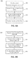
- FIG. 9A illustrates a method 900 for assembling a wheel assembly, in accordance with various embodiments.
- a wheel 310 may be provided (step 902).
- a heat insulator 540 may be disposed around and/or coupled to wheel 310 (step 904).
- Heat insulator 540 may be one continuous piece of material, or heat insulator 540 may be split circumferentially into any number of components, such as an inner heat insulator 542 and/or an outer heat insulator 544.
- heat insulator 540 may comprise ends 546 (as depicted in FIGS. 5A and 5B ) and may be wrapped around wheel 310.
- an insulator fastening device 560 may be coupled to heat insulator 540 (step 906) in any suitable manner, including those described herein.
- a tire may be disposed around wheel 310 (step 908) such that heat insulator 540 and/or insulator fastening device 560 is/are adjacent to the tire cavity.
- FIG. 9B illustrates a method 950 for assembling a wheel assembly, in accordance with various embodiments.
- a tire 320 may be disposed circumferentially around an inboard wheel half 813 (step 952).
- heat insulator 340 may be disposed circumferentially on inboard wheel half 813 (step 954) such that heat insulator 340 is located between inboard wheel half 813 and tire 320. Heat insulator 340 may be adjacent to tire cavity 324.
- insulator fastening device 560 may be coupled to heat insulator 340 (step 956).
- Insulator fastening device 560 may be coupled to heat insulator 340 in any suitable manner, including those discussed herein.
- outboard wheel half 815 may be coupled to inboard wheel half 813 (step 958).
- Outboard wheel half 815 may be coupled to inboard wheel half 813 in any suitable manner such as bolting, welding, locking, wedging, and/or the like.
- Outboard wheel half 815 may be coupled between inboard wheel half 813 and heat insulator 340.
- inboard wheel half 813 and outboard wheel half 815 may be coupled before heat insulator 340 is disposed on any part of the wheel.
- Inboard wheel half 813 and outboard wheel half 815 may make up a wheel body, such as wheel body 311 depicted in FIG. 3 .
- inboard wheel half 813 and outboard wheel half 815 may be integral with one another to form a wheel body, meaning one continuous piece of material, such as wheel body 311 in FIG. 3 .
- tire 320 and/or heat insulator 340 may be coupled circumferentially around the wheel body comprised of inboard wheel half 813 and outboard wheel half 813 in a method for assembling a wheel assembly, such as method 900 in FIG. 9A .
- heat insulator 340 may be one continuous circle and/or loop of material that is slid onto the wheel body.
- heat insulator 340 may be a strip of material that may be wrapped around the wheel body such that the ends of heat insulator 340, such as ends 546 depicted in FIGS. 5A and 5B , meet or otherwise couple.
- inboard wheel half 813 may comprise inboard outer diameter surface 830A and outboard wheel half 815 may comprise outboard outer diameter surface 830B. Together inboard outer diameter surface 830A and outboard outer diameter surface 830B may create an outer diameter surface, such as outer diameter surface 330 in FIG. 3 , for example.
- Heat insulator 340 may be disposed on the outer diameter surface comprised of both inboard outer diameter surface 830A and outboard outer diameter surface 830B.
- inboard wheel half 813 may comprise an inboard side 812 and an inner rim 817.
- Outboard wheel half 815 may comprise an outboard side 814 and an outer rim 818.
- Heat insulator 340 may be disposed between inner rim 817 and outer rim 818.
Landscapes
- Engineering & Computer Science (AREA)
- Mechanical Engineering (AREA)
- Aviation & Aerospace Engineering (AREA)
- Thermal Insulation (AREA)
Applications Claiming Priority (1)
| Application Number | Priority Date | Filing Date | Title |
|---|---|---|---|
| US15/094,127 US20170291696A1 (en) | 2016-04-08 | 2016-04-08 | Heat-insulated wheel |
Publications (1)
| Publication Number | Publication Date |
|---|---|
| EP3235657A1 true EP3235657A1 (de) | 2017-10-25 |
Family
ID=58267016
Family Applications (1)
| Application Number | Title | Priority Date | Filing Date |
|---|---|---|---|
| EP17160560.3A Withdrawn EP3235657A1 (de) | 2016-04-08 | 2017-03-13 | Wärmeisoliertes rad |
Country Status (2)
| Country | Link |
|---|---|
| US (1) | US20170291696A1 (de) |
| EP (1) | EP3235657A1 (de) |
Families Citing this family (2)
| Publication number | Priority date | Publication date | Assignee | Title |
|---|---|---|---|---|
| FR3093321B1 (fr) * | 2019-02-28 | 2021-06-18 | Safran Landing Systems | Roue d’aéronef pourvue d’écrans thermiques |
| US20210283958A1 (en) * | 2020-03-13 | 2021-09-16 | Goodrich Corporation | Wheel assembly with exterior fuse plug |
Citations (4)
| Publication number | Priority date | Publication date | Assignee | Title |
|---|---|---|---|---|
| US20110057504A1 (en) * | 2009-09-08 | 2011-03-10 | Honda Motor Co., Ltd. | Vehicle wheel |
| JP2012096755A (ja) * | 2010-11-05 | 2012-05-24 | Honda Motor Co Ltd | 車両用ホイール及びリム被覆材 |
| GB2500442A (en) * | 2012-08-21 | 2013-09-25 | Messier Dowty Ltd | Wheel having an electromagnetic braking assembly with a movable stator |
| DE102012102418A1 (de) * | 2012-03-21 | 2013-09-26 | Continental Reifen Deutschland Gmbh | Fahrzeugluftreifen |
Family Cites Families (12)
| Publication number | Priority date | Publication date | Assignee | Title |
|---|---|---|---|---|
| DE1252570B (de) * | 1957-02-27 | 1967-10-19 | ||
| US3035667A (en) * | 1959-11-04 | 1962-05-22 | Kelsey Hayes Co | Brake drum |
| US3448783A (en) * | 1967-06-09 | 1969-06-10 | Caterpillar Tractor Co | Tire bead shield |
| US3703317A (en) * | 1970-11-02 | 1972-11-21 | Goodyear Tire & Rubber | Vehicle wheel and brake with heat shield |
| US3929167A (en) * | 1974-10-29 | 1975-12-30 | Bruce T Bickel | Insulation device for protection against heat |
| FR2348067A1 (fr) * | 1976-04-12 | 1977-11-10 | Kleber Colombes | Pneumatique pour vehicule |
| ES1024028Y (es) * | 1993-03-15 | 1994-04-01 | Nadal Aloy | Dispositivo de estanqueidad para ruedas de radios sin camara. |
| US5538114A (en) * | 1994-12-19 | 1996-07-23 | Eaton Corporation | Insulating wheel mounting system for reduced heat transfer |
| CN102119087A (zh) * | 2008-04-03 | 2011-07-06 | 轮胎声学有限责任公司 | 轮胎和轮子噪声减小装置与系统 |
| JP4834715B2 (ja) * | 2008-10-21 | 2011-12-14 | 本田技研工業株式会社 | 車両用ホイール |
| JP4830014B2 (ja) * | 2009-09-08 | 2011-12-07 | 本田技研工業株式会社 | 車両用ホイール |
| US8663774B2 (en) * | 2010-04-23 | 2014-03-04 | Unifrax I Llc | Multi-layer thermal insulation composite |
-
2016
- 2016-04-08 US US15/094,127 patent/US20170291696A1/en not_active Abandoned
-
2017
- 2017-03-13 EP EP17160560.3A patent/EP3235657A1/de not_active Withdrawn
Patent Citations (4)
| Publication number | Priority date | Publication date | Assignee | Title |
|---|---|---|---|---|
| US20110057504A1 (en) * | 2009-09-08 | 2011-03-10 | Honda Motor Co., Ltd. | Vehicle wheel |
| JP2012096755A (ja) * | 2010-11-05 | 2012-05-24 | Honda Motor Co Ltd | 車両用ホイール及びリム被覆材 |
| DE102012102418A1 (de) * | 2012-03-21 | 2013-09-26 | Continental Reifen Deutschland Gmbh | Fahrzeugluftreifen |
| GB2500442A (en) * | 2012-08-21 | 2013-09-25 | Messier Dowty Ltd | Wheel having an electromagnetic braking assembly with a movable stator |
Also Published As
| Publication number | Publication date |
|---|---|
| US20170291696A1 (en) | 2017-10-12 |
Similar Documents
| Publication | Publication Date | Title |
|---|---|---|
| EP2503176B1 (de) | Wärmeschildinstallation für Flugzeugräder zur Verbesserung der Konvektionskühlung der Flugzeugbremse | |
| WO2006024010A3 (en) | Aerogel-based vehicle thermalmanagement systems and methods | |
| EP3235657A1 (de) | Wärmeisoliertes rad | |
| US20110284189A1 (en) | Reusable high temperature thermal protection system | |
| JPH09242798A (ja) | 更新可能な摩耗面を備えた摩擦ディスク | |
| US4703837A (en) | Thermally protected disk brake for a vehicle wheel, in particular for aircraft | |
| KR20130102038A (ko) | 터빈 케이싱 상에 쉴드를 장착하기 위한 방법 및 이를 수행하기 위한 장착 조립체 | |
| CA2950001C (en) | Bracketed support for a double walled cryogenic storage vessel | |
| EP3825570B1 (de) | Bremsscheibenanordnung | |
| US10167912B2 (en) | Plate assemblies including floating wear linings for multi-disk brake systems and methods for reducing vibration in a multi-disk brake system | |
| JP2015525329A (ja) | 断熱パイプ台 | |
| EP3115636A1 (de) | Bremsscheiben mit mehrblättrigem kern und anordnungen | |
| EP2283218B1 (de) | Wärmeisolationsstruktur | |
| EP3403849B1 (de) | Isolator gegen durch hohe reibung erzeugte wärme | |
| EP2994686B1 (de) | Befestigungssystem für wärmeschutzplatten | |
| EP4146537A1 (de) | Hitzeschild für eine bremsvorrichtung eines flugzeugrads | |
| US20110041945A1 (en) | Automotive Exhaust Pipe | |
| CN210950254U (zh) | 一种抗压直埋保温管 | |
| US20150362120A1 (en) | Pipe Insulation System and Method | |
| US11802603B2 (en) | High thermal conductivity heat shield | |
| CA2998064A1 (en) | Conveyor roll assembly, torque transmission and support means and process for making a conveyor roll assembly used in a high temperature environment. | |
| US9988155B2 (en) | System and method for aft mount of gas turbine engine | |
| US20040129309A1 (en) | Pneumatic wheel and tire overpressure protection method and apparatus | |
| US20190277357A1 (en) | Aircraft brake heat shield | |
| US20150315931A1 (en) | Device for connecting a fixed portion of a turbine engine and a distributor foot of a turbine engine turbine |
Legal Events
| Date | Code | Title | Description |
|---|---|---|---|
| PUAI | Public reference made under article 153(3) epc to a published international application that has entered the european phase |
Free format text: ORIGINAL CODE: 0009012 |
|
| STAA | Information on the status of an ep patent application or granted ep patent |
Free format text: STATUS: THE APPLICATION HAS BEEN PUBLISHED |
|
| AK | Designated contracting states |
Kind code of ref document: A1 Designated state(s): AL AT BE BG CH CY CZ DE DK EE ES FI FR GB GR HR HU IE IS IT LI LT LU LV MC MK MT NL NO PL PT RO RS SE SI SK SM TR |
|
| AX | Request for extension of the european patent |
Extension state: BA ME |
|
| STAA | Information on the status of an ep patent application or granted ep patent |
Free format text: STATUS: REQUEST FOR EXAMINATION WAS MADE |
|
| 17P | Request for examination filed |
Effective date: 20180424 |
|
| RBV | Designated contracting states (corrected) |
Designated state(s): AL AT BE BG CH CY CZ DE DK EE ES FI FR GB GR HR HU IE IS IT LI LT LU LV MC MK MT NL NO PL PT RO RS SE SI SK SM TR |
|
| GRAP | Despatch of communication of intention to grant a patent |
Free format text: ORIGINAL CODE: EPIDOSNIGR1 |
|
| STAA | Information on the status of an ep patent application or granted ep patent |
Free format text: STATUS: GRANT OF PATENT IS INTENDED |
|
| INTG | Intention to grant announced |
Effective date: 20210826 |
|
| STAA | Information on the status of an ep patent application or granted ep patent |
Free format text: STATUS: THE APPLICATION IS DEEMED TO BE WITHDRAWN |
|
| 18D | Application deemed to be withdrawn |
Effective date: 20220106 |