EP3234591B1 - Procédé et dispositif de détection optique d'un échantillon chromatographique - Google Patents
Procédé et dispositif de détection optique d'un échantillon chromatographique Download PDFInfo
- Publication number
- EP3234591B1 EP3234591B1 EP15797603.6A EP15797603A EP3234591B1 EP 3234591 B1 EP3234591 B1 EP 3234591B1 EP 15797603 A EP15797603 A EP 15797603A EP 3234591 B1 EP3234591 B1 EP 3234591B1
- Authority
- EP
- European Patent Office
- Prior art keywords
- sample plate
- illumination
- illumination device
- drawer
- sample
- Prior art date
- Legal status (The legal status is an assumption and is not a legal conclusion. Google has not performed a legal analysis and makes no representation as to the accuracy of the status listed.)
- Active
Links
Images
Classifications
-
- G—PHYSICS
- G01—MEASURING; TESTING
- G01N—INVESTIGATING OR ANALYSING MATERIALS BY DETERMINING THEIR CHEMICAL OR PHYSICAL PROPERTIES
- G01N30/00—Investigating or analysing materials by separation into components using adsorption, absorption or similar phenomena or using ion-exchange, e.g. chromatography or field flow fractionation
- G01N30/90—Plate chromatography, e.g. thin layer or paper chromatography
- G01N30/95—Detectors specially adapted therefor; Signal analysis
-
- G—PHYSICS
- G01—MEASURING; TESTING
- G01N—INVESTIGATING OR ANALYSING MATERIALS BY DETERMINING THEIR CHEMICAL OR PHYSICAL PROPERTIES
- G01N21/00—Investigating or analysing materials by the use of optical means, i.e. using sub-millimetre waves, infrared, visible or ultraviolet light
- G01N21/17—Systems in which incident light is modified in accordance with the properties of the material investigated
- G01N21/25—Colour; Spectral properties, i.e. comparison of effect of material on the light at two or more different wavelengths or wavelength bands
- G01N21/31—Investigating relative effect of material at wavelengths characteristic of specific elements or molecules, e.g. atomic absorption spectrometry
- G01N21/314—Investigating relative effect of material at wavelengths characteristic of specific elements or molecules, e.g. atomic absorption spectrometry with comparison of measurements at specific and non-specific wavelengths
- G01N21/3151—Investigating relative effect of material at wavelengths characteristic of specific elements or molecules, e.g. atomic absorption spectrometry with comparison of measurements at specific and non-specific wavelengths using two sources of radiation of different wavelengths
-
- G—PHYSICS
- G01—MEASURING; TESTING
- G01N—INVESTIGATING OR ANALYSING MATERIALS BY DETERMINING THEIR CHEMICAL OR PHYSICAL PROPERTIES
- G01N21/00—Investigating or analysing materials by the use of optical means, i.e. using sub-millimetre waves, infrared, visible or ultraviolet light
- G01N21/17—Systems in which incident light is modified in accordance with the properties of the material investigated
- G01N21/59—Transmissivity
- G01N21/5907—Densitometers
- G01N21/5911—Densitometers of the scanning type
-
- G—PHYSICS
- G02—OPTICS
- G02B—OPTICAL ELEMENTS, SYSTEMS OR APPARATUS
- G02B21/00—Microscopes
- G02B21/0004—Microscopes specially adapted for specific applications
- G02B21/002—Scanning microscopes
-
- G—PHYSICS
- G02—OPTICS
- G02B—OPTICAL ELEMENTS, SYSTEMS OR APPARATUS
- G02B21/00—Microscopes
- G02B21/06—Means for illuminating specimens
-
- G—PHYSICS
- G02—OPTICS
- G02B—OPTICAL ELEMENTS, SYSTEMS OR APPARATUS
- G02B21/00—Microscopes
- G02B21/24—Base structure
- G02B21/26—Stages; Adjusting means therefor
-
- G—PHYSICS
- G02—OPTICS
- G02B—OPTICAL ELEMENTS, SYSTEMS OR APPARATUS
- G02B21/00—Microscopes
- G02B21/36—Microscopes arranged for photographic purposes or projection purposes or digital imaging or video purposes including associated control and data processing arrangements
- G02B21/361—Optical details, e.g. image relay to the camera or image sensor
-
- H—ELECTRICITY
- H04—ELECTRIC COMMUNICATION TECHNIQUE
- H04N—PICTORIAL COMMUNICATION, e.g. TELEVISION
- H04N1/00—Scanning, transmission or reproduction of documents or the like, e.g. facsimile transmission; Details thereof
- H04N1/024—Details of scanning heads ; Means for illuminating the original
- H04N1/028—Details of scanning heads ; Means for illuminating the original for picture information pick-up
- H04N1/0281—Details of scanning heads ; Means for illuminating the original for picture information pick-up with means for collecting light from a line or an area of the original and for guiding it to only one or a relatively low number of picture element detectors
-
- H—ELECTRICITY
- H04—ELECTRIC COMMUNICATION TECHNIQUE
- H04N—PICTORIAL COMMUNICATION, e.g. TELEVISION
- H04N1/00—Scanning, transmission or reproduction of documents or the like, e.g. facsimile transmission; Details thereof
- H04N1/024—Details of scanning heads ; Means for illuminating the original
- H04N1/028—Details of scanning heads ; Means for illuminating the original for picture information pick-up
- H04N1/02815—Means for illuminating the original, not specific to a particular type of pick-up head
- H04N1/02845—Means for illuminating the original, not specific to a particular type of pick-up head using an elongated light source, e.g. tubular lamp, LED array
-
- H—ELECTRICITY
- H04—ELECTRIC COMMUNICATION TECHNIQUE
- H04N—PICTORIAL COMMUNICATION, e.g. TELEVISION
- H04N1/00—Scanning, transmission or reproduction of documents or the like, e.g. facsimile transmission; Details thereof
- H04N1/024—Details of scanning heads ; Means for illuminating the original
- H04N1/028—Details of scanning heads ; Means for illuminating the original for picture information pick-up
- H04N1/02815—Means for illuminating the original, not specific to a particular type of pick-up head
- H04N1/02895—Additional elements in the illumination means or cooperating with the illumination means, e.g. filters
-
- H—ELECTRICITY
- H04—ELECTRIC COMMUNICATION TECHNIQUE
- H04N—PICTORIAL COMMUNICATION, e.g. TELEVISION
- H04N1/00—Scanning, transmission or reproduction of documents or the like, e.g. facsimile transmission; Details thereof
- H04N1/04—Scanning arrangements, i.e. arrangements for the displacement of active reading or reproducing elements relative to the original or reproducing medium, or vice versa
-
- G—PHYSICS
- G01—MEASURING; TESTING
- G01N—INVESTIGATING OR ANALYSING MATERIALS BY DETERMINING THEIR CHEMICAL OR PHYSICAL PROPERTIES
- G01N21/00—Investigating or analysing materials by the use of optical means, i.e. using sub-millimetre waves, infrared, visible or ultraviolet light
- G01N21/17—Systems in which incident light is modified in accordance with the properties of the material investigated
- G01N2021/1765—Method using an image detector and processing of image signal
- G01N2021/177—Detector of the video camera type
- G01N2021/1772—Array detector
- G01N2021/1774—Line array detector
-
- G—PHYSICS
- G01—MEASURING; TESTING
- G01N—INVESTIGATING OR ANALYSING MATERIALS BY DETERMINING THEIR CHEMICAL OR PHYSICAL PROPERTIES
- G01N21/00—Investigating or analysing materials by the use of optical means, i.e. using sub-millimetre waves, infrared, visible or ultraviolet light
- G01N21/17—Systems in which incident light is modified in accordance with the properties of the material investigated
- G01N21/25—Colour; Spectral properties, i.e. comparison of effect of material on the light at two or more different wavelengths or wavelength bands
- G01N21/31—Investigating relative effect of material at wavelengths characteristic of specific elements or molecules, e.g. atomic absorption spectrometry
- G01N21/314—Investigating relative effect of material at wavelengths characteristic of specific elements or molecules, e.g. atomic absorption spectrometry with comparison of measurements at specific and non-specific wavelengths
- G01N2021/3155—Measuring in two spectral ranges, e.g. UV and visible
-
- G—PHYSICS
- G01—MEASURING; TESTING
- G01N—INVESTIGATING OR ANALYSING MATERIALS BY DETERMINING THEIR CHEMICAL OR PHYSICAL PROPERTIES
- G01N2201/00—Features of devices classified in G01N21/00
- G01N2201/10—Scanning
- G01N2201/101—Scanning measuring head
Definitions
- the invention relates to a method for optically detecting a chromatographic sample, wherein a sample plate having the sample illuminated with light of a first illumination device and the light emitted from the sample plate light from an optical detector device which reads line-shaped or field-shaped, is detected.
- Thin-layer chromatography is an analytical method that can be used to examine individual substances and the composition of samples.
- the sample to be tested is dissolved in a solvent and typically applied in a dot-shaped or line-shaped manner to a thin layer of a suitable, very fine-grained material such as, for example, silica gel or cellulose.
- the material layer referred to as a stationary phase or separating layer is in turn applied as uniformly as possible to a plate, usually a carrier plate or carrier foil made of plastic, aluminum, sheet metal or glass.
- the coated plate is also called sample plate or TLC plate.
- On a sample plate often several different samples are arranged side by side. After applying the samples to be measured, an edge of the sample plate is immersed in or wetted with a suitable flow agent.
- eluents can be used depending on the particular sample and the release layer material, for example, nonpolar organic solvents or polar solvents may be used, or mixtures thereof.
- the flow agent migrates through the fine-pored carrier material, the substances contained in a sample migrating at different speeds depending on the substance and thereby spatially separated and separated in the direction of travel of the flow agent and thus producing a sample path.
- the sample portions spatially separated in the direction of travel of the flow agent individual substances can be identified by a comparison with reference samples and optionally also quantitatively evaluated.
- optimized densitometers may be used for such evaluations, which are also referred to as "TLC scanners".
- TLC scanners The arranged on a sample plate and chromatographically separated samples are successively lit line by line with a point or strip-shaped light spot, or scanned and recorded the light emitted from the sample plate light with a densitometer.
- light with different wavelengths or wavelength ranges can be used, wherein in addition to a lighting with visible light, in particular a lighting with UV light is used. It is also possible to carry out UV absorption measurements or luminescence light measurements in order to obtain additional information about the substances contained in the sample.
- the commonly used commercial densitometers allow a precise quantitative evaluation of the individual samples on a sample plate.
- the optical detection of multiple samples placed on a sample plate and subsequently chromatographed is time consuming since the light spot used to illuminate the sample must be sequentially passed through the separation path associated with that sample for each sample and continuously emitted from the sample plate Light must be detected in order to be subsequently evaluated.
- the lighting devices used in each case must be activated at an early stage between individual measurements with different wavelength ranges and, in the case of UV lighting devices, must also be preheated on a regular basis in order to allow illumination of the sample panel as uniformly as possible during the entire measurement period.
- the optical detection of a sample plate with 5 to 10 samples therefore usually takes a few minutes and with a change of lighting even longer.
- such densitometers are expensive to manufacture and expensive during operation.
- a complete image of the sample plate can be taken with a suitable camera.
- the total image recorded by the sample plate can then be evaluated by suitable evaluation methods. It has been found that such overall image acquisition can be detected optically very quickly and the evaluation with software adapted to it also quickly and cost-effectively can be carried out.
- the sample plate sufficiently homogeneous and illuminate consistently over several measurements to allow a quantitative evaluation of the overall image.
- the sample plate with the coated and provided with the samples side down on a standard flatbed scanner can be placed.
- flatbed scanners modified from practice and provided with a UV light source are known.
- the handling of the sample plate and in particular the laying of the sample plate with the coated side on the glass cover of a flatbed scanner are problematic and lead to contamination.
- commercially available scanners by the Glass plate not suitable for UV detection at 254 nm.
- the displacement of the illumination device and the line-shaped optical detector device combined therewith is not sufficiently uniform and precise in the commercial flatbed scanners, so that a quantitative evaluation of the image recordings recorded with such flatbed scanners are not optimal for a reliable quantitative evaluation.
- a complete optical detection of a sample plate takes a comparatively long time, especially when changing the illumination between two successive image recordings.
- the handling of the sample plate should be as user-friendly as possible during the performance of a measurement process.
- a third illumination device is illuminated and a third measurement image of the sample plate is recorded.
- a measurement image is both an image acquisition, for example an image of a DC plate when illuminated with visible light (wavelength between 370 and 800 nm) or UV light (wavelength less than 370 nm) of different wavelengths or wavelength subregions, or a measurement data set such as a spectrum, for example. which is recorded with a spectrometer.
- a detector device which reads in a line-shaped or field-shaped manner, the measurement can be accelerated in comparison with punctiform measuring devices.
- a line-shaped detection means that a plurality of adjoining pixels are detected simultaneously in one expansion direction.
- Field-based detection means according to the invention that not only a number of adjacent pixels is detected, as is the case with the linear detection, but a plurality of adjacent rows of these pixels at the same time, so that a field of pixels is detected in two perpendicular to each other Directions includes two or more pixels.
- a particularly preferred detector device, which reads in the form of a line or in a field is a CCD sensor.
- a detector device which can detect adjacent pixels in line form or in the form of a line, is also called a line-shaped or field-shaped detector device.
- the illumination devices extend over the entire width of the sample plate to be illuminated. In this way, there is a very homogeneous illumination and illuminance over the entire width of the sample plate.
- the lighting devices may be, for example, tubular light sources or point-shaped light sources which are mounted in a row.
- the homogeneous illumination can preferably additionally be assisted by optical components, preferably refractive and / or scattering elements such as lenses or lenses (for example rod lenses). If optical components are used to support the homogeneous illumination, typically the distance of the point-shaped light sources can be increased. The skilled person is able to choose the distance of the point-shaped light sources with or without the addition of optical components so that a sufficiently homogeneous illumination over the entire width of the sample plate takes place.
- the illumination devices and the detector device are located above the sample plate, so that the upwardly directed side of the sample plate is measured.
- Each illumination device radiates in a certain wavelength subrange, ie it generates a certain wavelength subrange. These are particularly preferred white light LEDs for the visible range, UV LEDs at 366 nm for the UV-A range and mercury vapor lamps for the UV-C range (254 nm).
- LEDs with other wavelengths are LEDs with other wavelengths, halogen lamps or deuterium lamps.
- the wavelength subarea of the illumination devices may be additionally supplemented by e.g. Filter be restricted.
- the simplification is usually spoken by two lighting devices and two measuring steps.
- the person skilled in the art can also transmit the information provided for this purpose to devices and methods comprising three or more measuring steps and correspondingly three or more lighting devices.
- the evaluation of the measurement images can be combined with one another and the analysis can be improved by the additional information.
- lighting units are used which require a warm-up time, they are preferably already activated and preheated before their use, ie, for example, during a preceding measuring step. If, in the case of a lighting device that requires warm-up time, preferably in a preparation step, this lighting device is already activated and can preheat, before or during the first lighting device first Measurement image is recorded, no separate warm-up time is required before recording the second measurement image with the preheated lighting unit. With the already preheated second illumination device, a much more homogeneous and uniform illumination of the sample plate can be achieved during the acquisition of the second measurement image, which improves the reliability and precision of a quantitative evaluation of the second measurement image and thus of the entire quantitative analysis of the sample plate. In addition, the optical detection of the sample plate can be carried out in a short time, since no or only small waiting times before the start of recording a first or a second measurement image are required.
- the detector device and the illumination devices are not displaced, but the sample plate having a significantly lower dead weight is moved.
- the design effort for a rapid and precise displacement of the light sample plate is considerably less than the effort that would be required for a comparably precise and fast displacement of the detector device and the lighting devices. It can be achieved with a suitably designed drive means for moving the sample plate that the traversing speed of the sample plate is not limited by the configuration of the traversing device, but only by the maximum possible optical detection speed of the detector device.
- the measurement can be disturbed since, of course, when taking a measurement image only e.g. the luminescence or reflection is to be detected, which is generated by a lighting device.
- an opaque shield may be arranged in the region of the detector device or between the detector device and the second illumination device.
- the shield may be pivotable or linearly displaceable. If the second illumination device is a UV light source, which is advantageous because of the commonly required preheating of commercial UV sources, the detector device, for example, during the recording of the first measurement image covered with a UV-opaque shielding and thereby the UV light of the detector device are kept away.
- the invention it is preferred to shield the light from illumination devices, which are not needed in a measuring step, from the sample plate and the detector device during this measuring step.
- the light generated by the second illumination device is shielded not only by the detector device but also by the sample plate and the illumination of the sample plate is effected exclusively by the first illumination device.
- unwanted disturbances and overlays of a first measurement image in the e.g. visible wavelength range to be generated by visible light illumination of the first illumination device with the light emitted by the second illumination device e.g. UV light and any fluorescent light possibly generated thereby in the sample can be avoided.
- the second displacement direction is opposite to the first displacement direction and each further displacement direction is in turn opposite to the preceding one.
- the sample plate for taking the first measurement image can be moved in a first direction under the detector device and the illumination devices, in order subsequently to be reversed in the opposite direction while the second measurement image is being taken. In this case there are no additional travel paths and no corresponding waiting times between consecutive shots of measurement images required.
- information from the first measurement image will be used to record the second measurement image. In particular, this information regarding the position of the sample plate, calibration of the lamps or the white balance. The processing of the information preferably takes place via a corresponding evaluation software.
- a device for optically detecting a chromatographic sample with a recording device for a sample plate, with a first illumination device and with an optical detector device which reads line-shaped or field-shaped.
- the receiving device has a carrier displaceable relative to the detector device in a first displacement direction for receiving the sample plate, that the first illumination device and a second illumination device each extend preferably over a maximum width of a recordable in the receiving device sample plate and in each case parallel to the line-shaped or field- shaped detector device and are aligned transversely to the first direction of displacement, and that the device is preferably designed such that during a recording of a measurement image, the sample is illuminated only with a wavelength sub-range.
- a support for receiving the sample plate for example, a forward and backward operable conveyor belt, a displaceable support plate or preferably a drawer are suitable.
- a conveyor belt can transport the sample plate quickly and precisely in a direction of displacement and transport it back in the opposite direction of displacement in a second measuring step.
- a drawer in which a sample plate is inserted, can be moved quickly and precisely with little design effort.
- the insertion of a sample plate in a drawer and the subsequent removal of the sample plate after performing the measurements can be made simple and user-friendly.
- suitable positioning aids such as spring-operated terminals, stop elements in the form of webs or elevations or latching displaceable stop elements sample plates with different formats, or dimensions can be reliably positioned and fixed in a simple manner within the drawer.
- the drawer may be provided with a recess for receiving sample plates or be executed without a recess.
- the sample plate is placed on the flat drawer.
- the drawer on webs or surveys for fixing the sample plate. Slippage of the sample plate or an obliquely applied sample plate can, if necessary, additionally be compensated by a suitable image recording software. It can one or more sample plates are placed and measured simultaneously.
- the drawer with the sample plate received therein only once transversely to the detector device over the length of the sample plate must be moved to a complete measurement image of the sample plate to be able to record.
- a very uniform and constant illumination of the sample plate can be achieved.
- the device is designed in such a way that, during a recording of a measurement image, the sample is illuminated with only one wavelength subarea in order to obtain two different measurement images with complementary information for a better evaluation on the sample plate by changing the wavelength subarea between two consecutive measurement images in a short time to allow samples located.
- the device has a shielding device with which a wavelength sub-area is shielded from the detector device during a recording of a measurement image.
- the shielding may be effected, for example, by means of opaque shielding plates or by means which may optionally be arranged in an area around the detector means such that either only of the first illumination device or only from the second illumination device can reach light on the sample plate and in the detector device. It is also conceivable that, during successive recordings of measurement images by the use of suitable filter devices, different wavelength subareas can be shielded by the detector device.
- a wavelength subregion of the illumination generated by the first illumination device or by the second illumination device and / or by further illumination devices from the sample plate.
- the acquisition of a measurement image preferably takes place in such a way that only the wavelength subregion generated by an illumination device strikes the sample plate. All other active lighting devices are screened. It is also possible, by means of appropriate filters, to further restrict the wavelength subregion of the illumination device, which illuminates the sample plate in the respective measuring step.
- the detector device has not just one but two and several different optical sensor devices which are sensitive in the same or preferably different or at least partially non-overlapping wavelength subregions.
- a first measurement image with a first sensor device and a second measurement image with a second sensor device are recorded.
- sensor devices are CCD sensors (CCD means charge-coupled device), contact image sensors (contact image sensors) and microspectrometer for recording substance spectra.
- the detector device preferably contains at least one CCD sensor.
- the CCD sensor and the sample plate are preferably one or more optical elements such as lenses and mirrors, to image the image of the sample plate on the sensor device.
- the second illumination device if it requires warm-up time, is already activated and preheated, while first a first measurement image is taken with the first illumination device before a second measurement image is taken with the second illumination device.
- the light of the illumination devices is preferably directed exclusively to the sample plate. This can for example be done by the light sources are inserted into a U-profile or a box that is open only to the side of the sample plate.
- the inner, directed to the light source wall of the U-profile or box can be additionally coated to increase the reflections.
- Advantage of this embodiment is a direct alignment of the light on the measuring range without stray light influences by undirected light scattering.
- the detector device be less than 100 millimeters, preferably less than 30 millimeters, above the carrier, e.g. a top of the drawer, is arranged.
- the first illuminator and the second illuminator may also be less than 100 millimeters, preferably less than 30 millimeters above the carrier, e.g. the top of the drawer, be arranged. This allows the device to be designed very compact. As the top of the drawer here the support surface of the drawer is called for the sample plate.
- An unwanted leakage of UV light during a measurement can be largely avoided by suitable shielding and sealing devices, whereby the reliability of the device is increased during the performance of measurements.
- the device has a housing in which at least the first illumination device and the second illumination device, the optical detector device and a drive means for the carrier, such as a drawer, are arranged.
- the housing in the case of a drawer as a carrier has a drawer slot through which the drawer at least partially moved out of the housing and can be retracted into the housing. In the drawer at least partially moved out of the case, a sample plate can be easily inserted and then easily removed again.
- the housing can be made very compact, so that the device may also be designed to be transportable and arranged for example in a suitcase or in a box and thereby can be transported easily and protected.
- the first illumination device, the second illumination device, optional further illumination devices and the optical detector device are shielded by the housing from the environment, so that an undesired impairment or falsification of the individual images of measurement images by ambient light or environmental influences can be largely excluded.
- the UV light generated by the illumination device used for this purpose can not be inadvertently radiated into the environment.
- an optionally available suitable sensor device on or in the drawer slot can be detected whether a sample plate is in the drawer. moreover can be detected by a suitable embodiment of the sensor device and the size of the sample plate, so that the recording and evaluation of the measurement images on the dimensions of the sample plate inserted in the drawer limited and the process can be accelerated.
- the detection of the position of the sample plate is carried out with an image analysis software.
- the image analysis software recognizes where and with which dimensions the sample plate is located.
- the found sample plate is virtually straightened by means of the analysis of the edges of the image. In this way, an exact alignment of the sample plate when inserting onto the carrier becomes unnecessary. Because the sizes of the sample plates are also detected, the recording and evaluation of the measurement images can be limited to the dimension of the inserted sample plate. This speeds up the process.
- the image analysis software can also make an angle correction of sample zones within a sample path. In this way, deviating from the flow direction of the eluent, inclined sample paths can be detected as such.
- the housing has an outlet slot for the drawer on a housing side opposite the drawer slot.
- the housing does not have to be so large that the housing for the sample plate provided drawer can be stored completely within the housing. Rather, it is possible and expedient with regard to a small, lightweight and portable measuring device that the housing is adapted to the space requirements of the lighting devices, the optical detector device and the drive device for the drawer and limited thereto.
- the housing may have a significantly smaller base area than the drawer, which only has to be drawn in on one side through the drawer slot and transported past the detector device, but can emerge again on an opposite side through an exit slot, since only a strip-shaped or field-shaped area of the sample plate must be illuminated and must be located for the detection of a measurement image in a detection range of the detector device.
- the arrangement of the detector device between the first illumination device and the second illumination device both a very compact design and a uniform illumination and precise detection of the radiated from the sample plate light can be achieved with the detector device.
- further illumination devices are arranged next to or in an area in the vicinity of the detector device, in order to use three or more different wavelength subareas various methods to perform measurements and to be able to take measurement images.
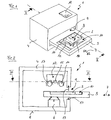
- Exemplary illustrated device 1 for optically detecting a sample plate 2, on which a plurality of chromatographic samples 3 are arranged, has a housing 4 and a displaceably mounted therein Drawer 5 on.
- the drawer 5 can be moved with a drive device 6 along a displacement direction back and forth, which is indicated by an arrow 7.
- the drawer 5 can be parallel to a housing base 8 by a drawer slot 9 partially out of the housing 4 and back into the housing 4 and retracted.
- the drawer 5 is shown in a fully extended, or partially extended state.
- the drawer 5 has a recess 10 accessible from above, in which the sample plate 2 is located.
- the sample plate 2 is pressed by laterally arranged in the recess 10 spring tongues 11 in a corner of the recess 10 and thereby reliably positioned within the recess 10, which is larger than the sample plate 2 therein.
- the plate formats commonly used for thin-layer chromatography for example 20 ⁇ 20 centimeters or 20 ⁇ 10 centimeters in the recess 10 of the drawer 5.
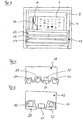
- a measuring head 12 is attached in the housing above the drawer 5, a measuring head 12 is attached.
- a first illumination device 13, a second illumination device 14 and a line-shaped or field-shaped optical detector device 15 are arranged such that light emitted by the first illumination device 13 or by the second illumination device 14 extends below the measurement head 12 illuminated area of the sample plate 2 and the radiated from the sample plate 2 Light from the detector device 15 can be detected and recorded.
- the first illumination device 13 emits, for example, light in a visible wavelength range.
- the second illumination device 14 emits, for example, UV light. Both the light in the visible wavelength range and the visible luminescence generated by the excitation with UV light can be detected and recorded with the detector device 15 which detects in a line-shaped or field-shaped manner.
- the sample plate 2 In order to carry out a measurement, the sample plate 2 must first be inserted into the recess 10 of the drawer 5 and, for example, fixed with the aid of the spring tongues 11. Before the start of a first recording, the second illumination device 14 is activated and preheated. With one in the FIGS. 1 to 3 not shown, the second illumination device 14 is covered to prevent UV light from falling onto the sample plate 2 during the warm-up period and when a first image is taken.
- the first lighting device 13 is also activated, and the drawer 5, which has still been moved out of the housing 4, is uniformly drawn into the housing 4 and thereby passes beneath the detector device 15.
- the sample plate 2 arranged in the recess 10 is illuminated with visible light by the first illumination device 13 and the light emitted by the sample plate 2 is detected by the detector device 15. In this way, a first measurement image is recorded.
- the first illumination device 13 is switched off and the cover is removed from the second illumination device 14, so that the sample plate 2 is no longer illuminated with visible light but with UV light.
- the drawer 5 with the sample plate 2 received therein is again moved in an opposite direction of displacement under the detector device 15 which detects in a line-shaped or field-shaped manner and thereby moved out of the housing 4 through the drawer slot 9. Since the second illumination device 14 was preheated during the exposure time of the first measurement image, the sample plate 2 is illuminated uniformly by the second illumination device 15 during the acquisition of the second measurement image.
- the first illumination device 13, the second illumination device 14 and the detector device 15 are each formed strip-shaped or tubular and arranged transversely to the direction indicated by the arrow 7 displacement direction in the housing 4, or aligned.
- the first illumination device 13, the second illumination device 14 and the detector device 15 extend with their ends or with their detection range beyond the edges of the recess 10 in the drawer 5, so that a very homogeneous illumination and illuminance over the entire surface of the sample plate. 2 can be reached.
- a reference strip 16 is optionally mounted laterally next to the recess 10 on the drawer 5, which can also be illuminated during a measurement process and recorded together with the sample plate 2 in the measurement image.
- the brightness in the areas which are not exposed to a sample is preferably measured and used as a reference.
- the drawer slot 9 optionally below the drawer 5, a brush strip 17 and preferably above the drawer 5 a shielding strip 18.
- the shielding strip 18 is mounted pivotably and simultaneously serves as a sensor device. If a sample plate 2 is not properly inserted into the recess 10 of the drawer 5 or additional items are on top of the drawer 5 and therefore the pivotable AbnestMail 18 is deflected during a displacement of the drawer 5, the measuring process can be interrupted and, for example, a safety shutdown Lighting devices 13 and 14 and the drive are made.
- the interior of the housing is black, more preferably it is black and anodized.
- a touch-sensitive display 19 allows easy operation of the device 1 and can be used simultaneously to display first information during the performance of a measuring operation.
- the shielding of the ambient light or the UV light is not or not only by Abnapst Shape or Ablebürsten but alone or additionally by other shielding such as flaps, curtains, etc.
- the two or more illumination devices and the detector device are preferably located above the carrier in a fixed, non-displaceable measuring head 12.
- the measuring head can furthermore contain shielding devices as well as optical devices, such as mirrors or objectives that support image acquisition, or also refractive and / or light-scattering elements that allow a more homogeneous illumination.
- a measuring head 12 is shown, in addition to to the detector device 15 and the first illumination device 13 and the second illumination device 14, a third illumination device 20 is arranged.
- the first illumination device 13 emits light in a visible wavelength range.
- the second illumination device 14 is a mercury-vapor lamp which emits UVC light having a wavelength of typically 254 nm by means of suitable optical elements or a plurality of strip-like UV LEDs.
- the third illumination device 20 has a number of strip-type light-emitting diodes or a mercury-vapor lamp, which likewise emits light with a wavelength of typically 366 nm and with a very homogeneous illuminance in conjunction with suitable optical components.
- a UV-light-impermeable shielding device 21 can be detected during the first measurement process shield the detector device 15.
- the first illumination device 13, which emits visible light, and the third illumination device 20, for example consisting of LEDs, do not require a preheating time and can each be activated for the duration of the relevant measuring process and then switched off again.
- the measuring head 12 in front of the first illumination device 13 and in front of the second illumination device 14 each have a displaceable shielding device 22, with which the relevant illumination device 13, 14 can be shielded or released.
- sample plates are therefore all samples that can be taken up by a wearer of a device according to the invention, such as thin-layer chromatography plates, gels, agar plates, test strips, circuit boards, etching plates, tissue sections, samples of paper, plastic, metal, minerals, granules.
- the sample plate is a thin-layer chromatography plate.
- the carrier may receive one or more sample plates.
- the carrier for example in the form of a drawer 5, can also be completely removed from the housing 4 and used again to carry out measurements.
- the sample plate 2 can already be arranged in the drawer before or during the chromatographic separation of the samples arranged thereon and thereby during preparatory or subsequent Process steps protected stored and transported.
Landscapes
- Physics & Mathematics (AREA)
- General Physics & Mathematics (AREA)
- Chemical & Material Sciences (AREA)
- Analytical Chemistry (AREA)
- Engineering & Computer Science (AREA)
- Multimedia (AREA)
- Signal Processing (AREA)
- Health & Medical Sciences (AREA)
- Biochemistry (AREA)
- General Health & Medical Sciences (AREA)
- Life Sciences & Earth Sciences (AREA)
- Immunology (AREA)
- Pathology (AREA)
- Optics & Photonics (AREA)
- Spectroscopy & Molecular Physics (AREA)
- Toxicology (AREA)
- Investigating Or Analysing Materials By Optical Means (AREA)
- Investigating, Analyzing Materials By Fluorescence Or Luminescence (AREA)
Claims (13)
- Procédé pour le scannage optique d'un échantillon chromatographique (3), dans lequel, lors d'une première étape de mesure, une plaque à échantillon(s) (2) qui contient l'échantillon (3) est éclairée à l'aide d'une lumière qui provient d'un premier dispositif d'éclairage (13) et la lumière qui est émise par la plaque à échantillon(s) (2) est détectée au moyen d'un dispositif de détecteur optique (15) qui effectue une lecture ligne par ligne ou zone par zone, et une première image de mesure de la plaque à échantillon(s) (2) est enregistrée, opération pendant laquelle la plaque à échantillon(s) (2) est déplacée dans une première direction de déplacement par rapport au dispositif de détecteur (15), et procédé selon lequel, lors d'une deuxième étape de mesure subséquente, la plaque à échantillon(s) (2) est déplacée dans une deuxième direction de déplacement par rapport au dispositif de détecteur (15) tandis qu'elle est éclairée au moyen du deuxième dispositif d'éclairage (14) et une deuxième image de mesure de la plaque à échantillon(s) (2) est enregistrée et dans lequel les dispositifs d'éclairage (13, 14) et le dispositif de détecteur (15) sont localisés au-dessus de la plaque à échantillon(s) et les dispositifs d'éclairage (13, 14) s'étendent au-dessus de la totalité de la largeur de la plaque à échantillon(s) qui doit être éclairée.
- Procédé selon la revendication 1, caractérisé en ce que, lors d'une troisième étape de mesure subséquente, la plaque à échantillon(s) (2) est déplacée dans une troisième direction de déplacement par rapport au dispositif de détecteur (15), elle est éclairée au moyen d'un troisième dispositif d'éclairage (20) et une troisième image de mesure de la plaque à échantillon(s) (2) est enregistrée.
- Procédé selon une ou plusieurs des revendications qui précèdent, caractérisé en ce que le deuxième dispositif d'éclairage (14) et/ou le troisième dispositif d'éclairage sont/est activé(s) au niveau d'une étape de préparation avant et/ou pendant une étape de mesure précédente.
- Procédé selon une ou plusieurs des revendications qui précèdent, caractérisé en ce que la lumière qui est générée par le deuxième dispositif d'éclairage (14) est évacuée par filtrage hors de la plaque à échantillon(s) (2) pendant la première étape de mesure.
- Procédé selon une ou plusieurs des revendications qui précèdent, caractérisé en ce que la deuxième direction de déplacement est opposée à la première direction de déplacement.
- Procédé selon une ou plusieurs des revendications qui précèdent, caractérisé en ce qu'une information en provenance de la première image de mesure est utilisée pour l'enregistrement de la deuxième image de mesure.
- Dispositif (1) pour mettre en oeuvre le procédé selon la revendication 1, comportant un moyen de support pour une plaque à échantillon(s) (2), lequel comporte un premier dispositif d'éclairage (13) et lequel comporte un dispositif de détecteur optique (15), dans lequel le dispositif de détecteur (15) effectue une lecture ligne par ligne ou zone par zone, dans lequel le moyen de support comporte un moyen de contenance et de support (5) pour la réception de la plaque à échantillon(s) (2), laquelle peut être déplacée dans une première direction de déplacement et dans une deuxième direction de déplacement par rapport au dispositif de détecteur (15), dans lequel le dispositif de détecteur (15), le premier dispositif d'éclairage (13) et un deuxième dispositif d'éclairage (14) s'étendent chacun au-dessus de la totalité de la largeur de la plaque à échantillon(s) (2), laquelle peut être logée dans le moyen de support, et le premier dispositif d'éclairage (13) et le deuxième dispositif d'éclairage (14) sont chacun orientés parallèlement au dispositif de détecteur ligne par ligne ou zone par zone (15) et perpendiculairement aux première et deuxième directions de déplacement et dans lequel le dispositif de détecteur (15) et les dispositifs d'éclairage (13, 14) sont agencés à moins de 100 mm au-dessus du moyen de contenance et de support (5).
- Dispositif (1) selon la revendication 7, caractérisé en ce que le moyen de contenance et de support est un compartiment formant tiroir (5).
- Dispositif (1) selon la revendication 7 ou la revendication 8, caractérisé en ce qu'une plage partielle de longueurs d'onde est évacuée par filtrage hors de la plaque à échantillon(s) (2) pendant un enregistrement d'une image de mesure.
- Dispositif (1) selon la revendication 8 ou les revendications 9 et 8, caractérisé en ce que le dispositif (1) comporte un logement (4) dans lequel le premier dispositif d'éclairage (13) et le deuxième dispositif d'éclairage (14), le dispositif de détecteur optique (15) et le dispositif d'entraînement (6) pour le compartiment formant tiroir (5) sont agencés, et en ce que le logement (4) comporte une fente de tiroir (9) au travers de laquelle le compartiment formant tiroir (5) peut être partiellement déplacé pour son extraction hors du logement (4) et peut être déplacé pour son positionnement à l'intérieur du logement (4).
- Dispositif (1) selon la revendication 10, caractérisé en ce que la fente de tiroir (9) comporte un dispositif de capteur pour détecter une plaque à échantillon(s) (2).
- Dispositif (1) selon la revendication 10 ou la revendication 11, caractérisé en ce que le logement (4) comporte une fente de sortie pour le compartiment formant tiroir (5) sur un côté de logement qui est opposé à la fente de tiroir (9).
- Dispositif (1) selon l'une des revendications 7 à 12, caractérisé en ce que le dispositif de détecteur (15) est agencé entre le premier dispositif d'éclairage (13) et le deuxième dispositif d'éclairage (14).
Applications Claiming Priority (3)
| Application Number | Priority Date | Filing Date | Title |
|---|---|---|---|
| EP14004313 | 2014-12-19 | ||
| EP15000889 | 2015-03-26 | ||
| PCT/EP2015/002336 WO2016096078A1 (fr) | 2014-12-19 | 2015-11-20 | Procédé et dispositif de détection optique d'un échantillon chromatographique |
Publications (2)
| Publication Number | Publication Date |
|---|---|
| EP3234591A1 EP3234591A1 (fr) | 2017-10-25 |
| EP3234591B1 true EP3234591B1 (fr) | 2019-06-19 |
Family
ID=54608484
Family Applications (1)
| Application Number | Title | Priority Date | Filing Date |
|---|---|---|---|
| EP15797603.6A Active EP3234591B1 (fr) | 2014-12-19 | 2015-11-20 | Procédé et dispositif de détection optique d'un échantillon chromatographique |
Country Status (5)
| Country | Link |
|---|---|
| US (1) | US10578595B2 (fr) |
| EP (1) | EP3234591B1 (fr) |
| JP (1) | JP6668353B2 (fr) |
| CN (1) | CN107003290B (fr) |
| WO (1) | WO2016096078A1 (fr) |
Families Citing this family (6)
| Publication number | Priority date | Publication date | Assignee | Title |
|---|---|---|---|---|
| WO2019069893A1 (fr) * | 2017-10-05 | 2019-04-11 | パナソニックIpマネジメント株式会社 | Procédé de détection de biomolécules |
| US10962511B2 (en) | 2017-12-12 | 2021-03-30 | Phoseon Technology, Inc. | Systems for a modular multi-wavelength absorbance detector |
| CH715116A1 (de) * | 2018-06-21 | 2019-12-30 | Camag Chemie Erzeugnisse Und Adsorptionstechnik Ag | Verfahren und Vorrichtung zur automatischen Chromatographie von Dünnschichtplatten. |
| CN110749589B (zh) * | 2019-11-26 | 2024-08-20 | 黎明职业大学 | 一种拉曼光谱鉴定宝石装置及其方法 |
| WO2022101373A1 (fr) * | 2020-11-16 | 2022-05-19 | Merck Patent Gmbh | Procédé d'évaluation d'une plaque de chromatographie à couche mince |
| EP4473306A1 (fr) * | 2022-01-31 | 2024-12-11 | Syngenta Crop Protection AG | Procédé et dispositif de détermination quantitative rapide de charge de traitement de semences |
Family Cites Families (14)
| Publication number | Priority date | Publication date | Assignee | Title |
|---|---|---|---|---|
| JP2815506B2 (ja) * | 1992-04-14 | 1998-10-27 | 株式会社日立製作所 | 光検出型電気泳動装置 |
| JPH10213865A (ja) * | 1997-01-30 | 1998-08-11 | Fuji Photo Film Co Ltd | 画像読み取り装置 |
| DE19811150C2 (de) * | 1998-03-14 | 2002-05-02 | Bernd Spangenberg | Dünnschichtchromatographiegerät |
| US6096205A (en) * | 1998-05-13 | 2000-08-01 | The Regents Of The University Of California | Hand portable thin-layer chromatography system |
| FR2786352B1 (fr) * | 1998-11-24 | 2004-10-22 | Ar2I Sa Analyses Rech S Et Inn | Appareil d'acquisition d'images par fluorescence et systeme d'imagerie comportant un tel appareil |
| SE9804606D0 (sv) * | 1998-12-30 | 1998-12-30 | Amersham Pharm Biotech Ab | Method and device for measuring labels in a carrier |
| CN101175986B (zh) * | 2005-04-06 | 2010-10-13 | 康宁股份有限公司 | 玻璃检测系统及其使用方法 |
| CN2884737Y (zh) * | 2006-03-01 | 2007-03-28 | 陈奎发 | 荧光成像扫描仪 |
| CN103814289A (zh) * | 2011-07-22 | 2014-05-21 | 比奥森西亚专利有限公司 | 用于发光免疫测定的读取器装置 |
| CN202599864U (zh) * | 2012-04-11 | 2012-12-12 | 法国圣戈班玻璃公司 | 光学测量装置 |
| JP5963518B2 (ja) | 2012-04-23 | 2016-08-03 | 株式会社椿本チエイン | 薄層クロマトグラフィ撮影装置 |
| JPWO2014077142A1 (ja) * | 2012-11-14 | 2017-01-05 | コニカミノルタ株式会社 | クロマトグラフィー試験片、クロマトグラフィー試験方法及びメンブレン |
| WO2015017046A1 (fr) * | 2013-07-31 | 2015-02-05 | The Regents Of The University Of California | Imagerie par fluorescence au moyen d'un scanneur à plat |
| CN204008581U (zh) * | 2014-08-18 | 2014-12-10 | 上海科哲生化科技有限公司 | 全波长荧光型薄层色谱扫描仪 |
-
2015
- 2015-11-20 US US15/536,679 patent/US10578595B2/en active Active
- 2015-11-20 WO PCT/EP2015/002336 patent/WO2016096078A1/fr not_active Ceased
- 2015-11-20 CN CN201580068765.1A patent/CN107003290B/zh active Active
- 2015-11-20 EP EP15797603.6A patent/EP3234591B1/fr active Active
- 2015-11-20 JP JP2017532774A patent/JP6668353B2/ja active Active
Non-Patent Citations (1)
| Title |
|---|
| None * |
Also Published As
| Publication number | Publication date |
|---|---|
| WO2016096078A1 (fr) | 2016-06-23 |
| JP6668353B2 (ja) | 2020-03-18 |
| US20170336371A1 (en) | 2017-11-23 |
| CN107003290B (zh) | 2020-09-01 |
| US10578595B2 (en) | 2020-03-03 |
| EP3234591A1 (fr) | 2017-10-25 |
| JP2017538943A (ja) | 2017-12-28 |
| CN107003290A (zh) | 2017-08-01 |
Similar Documents
| Publication | Publication Date | Title |
|---|---|---|
| EP3234591B1 (fr) | Procédé et dispositif de détection optique d'un échantillon chromatographique | |
| DE69929901T2 (de) | Inspektionssystem für die oberfläche von zylindrischen objekten | |
| DE112014004645B4 (de) | System und Verfahren zur Inspektion feuchter Kontaktlinsen | |
| DE69125574T2 (de) | Vorrichtung zur Auswertung fluoreszenzmarkierter Gelelektrophoresemuster | |
| DE69129518T3 (de) | Abtaster für Druckmuster | |
| DE69912577T2 (de) | Vorrichtung und verfahren zur optischen inspektion | |
| DE19844500A1 (de) | Verfahren zur photometrischen Auswertung von Testelementen | |
| DE10121064A1 (de) | Vorrichtung und Verfahren zur optischen Messung von chemischen und/oder biologischen Proben | |
| DE2606481C3 (de) | Fluorometer | |
| EP3488243A1 (fr) | Dispositif et procédé de détection permettant de détecter des identificateurs présents sur des objets de laboratoire et/ou des caractéristiques desdits objets | |
| DE10297337T5 (de) | Automatischer Inspektionsapparat und Verfahren zur Erkennung von Anomalien in einem 3-dimensionalen transluzenten Objekt | |
| EP3839476A1 (fr) | Dispositif et procédé de détermination d'une position et/ou d'une extension d'une goutte | |
| DE69934457T2 (de) | Analysevorrichtung für Teststreifen | |
| DE10156804B4 (de) | Optische Meßvorrichtung für Teststreifen | |
| DE69910065T2 (de) | Vorrichtung zur fluoreszenz-bild-erfassung und bildformungssystem mit einer solchen vorrichtung | |
| DE102017110080B4 (de) | Verfahren und Vorrichtung zur Detektion von Oberflächendefekten einer Oberfläche | |
| EP3470822B1 (fr) | Dispositif de détermination de coefficients de réflexion sur des couches fines | |
| EP3649501A1 (fr) | Procédé d'analyse d'un liquide contenant au moins une cellule et/ou au moins une particule | |
| EP3543681A1 (fr) | Système de détection destiné à la détection des petites particules organiques spécifiques sur verre non revêtu ou revêtu à haut débit | |
| WO1997036168A1 (fr) | Systeme d'evaluation quantitative a resolution locale d'elements d'analyse | |
| DE60115064T2 (de) | Analyseeinrichtung und -verfahren für flüssigkeitshaltige substanzen | |
| EP1441216A2 (fr) | Dispositif et méthode pour observer des réactions dans des échantillons | |
| EP3104164B1 (fr) | Systeme de mesure destine a la surveillance de la qualite de tablettes | |
| DE102020127071B3 (de) | Verfahren und Mikroskop mit einer Einrichtung zum Erfassen von Verlagerungen einer Probe gegenüber einem Objektiv | |
| EP3462164A1 (fr) | Dispositif et procédé d'inspection d'objets en forme de plaque mobiles |
Legal Events
| Date | Code | Title | Description |
|---|---|---|---|
| STAA | Information on the status of an ep patent application or granted ep patent |
Free format text: STATUS: THE INTERNATIONAL PUBLICATION HAS BEEN MADE |
|
| PUAI | Public reference made under article 153(3) epc to a published international application that has entered the european phase |
Free format text: ORIGINAL CODE: 0009012 |
|
| STAA | Information on the status of an ep patent application or granted ep patent |
Free format text: STATUS: REQUEST FOR EXAMINATION WAS MADE |
|
| 17P | Request for examination filed |
Effective date: 20170601 |
|
| AK | Designated contracting states |
Kind code of ref document: A1 Designated state(s): AL AT BE BG CH CY CZ DE DK EE ES FI FR GB GR HR HU IE IS IT LI LT LU LV MC MK MT NL NO PL PT RO RS SE SI SK SM TR |
|
| AX | Request for extension of the european patent |
Extension state: BA ME |
|
| DAV | Request for validation of the european patent (deleted) | ||
| DAX | Request for extension of the european patent (deleted) | ||
| GRAP | Despatch of communication of intention to grant a patent |
Free format text: ORIGINAL CODE: EPIDOSNIGR1 |
|
| STAA | Information on the status of an ep patent application or granted ep patent |
Free format text: STATUS: GRANT OF PATENT IS INTENDED |
|
| RIC1 | Information provided on ipc code assigned before grant |
Ipc: G02B 21/36 20060101ALI20181217BHEP Ipc: H04N 1/04 20060101ALI20181217BHEP Ipc: G02B 21/26 20060101ALI20181217BHEP Ipc: G01N 30/95 20060101AFI20181217BHEP Ipc: H04N 1/024 20060101ALI20181217BHEP Ipc: G01N 21/59 20060101ALI20181217BHEP Ipc: H04N 1/028 20060101ALI20181217BHEP Ipc: G01N 21/31 20060101ALI20181217BHEP Ipc: G01N 21/17 20060101ALI20181217BHEP Ipc: G02B 21/06 20060101ALI20181217BHEP |
|
| INTG | Intention to grant announced |
Effective date: 20190122 |
|
| GRAS | Grant fee paid |
Free format text: ORIGINAL CODE: EPIDOSNIGR3 |
|
| GRAA | (expected) grant |
Free format text: ORIGINAL CODE: 0009210 |
|
| STAA | Information on the status of an ep patent application or granted ep patent |
Free format text: STATUS: THE PATENT HAS BEEN GRANTED |
|
| AK | Designated contracting states |
Kind code of ref document: B1 Designated state(s): AL AT BE BG CH CY CZ DE DK EE ES FI FR GB GR HR HU IE IS IT LI LT LU LV MC MK MT NL NO PL PT RO RS SE SI SK SM TR |
|
| REG | Reference to a national code |
Ref country code: GB Ref legal event code: FG4D Free format text: NOT ENGLISH |
|
| REG | Reference to a national code |
Ref country code: CH Ref legal event code: EP |
|
| REG | Reference to a national code |
Ref country code: IE Ref legal event code: FG4D Free format text: LANGUAGE OF EP DOCUMENT: GERMAN |
|
| REG | Reference to a national code |
Ref country code: DE Ref legal event code: R096 Ref document number: 502015009404 Country of ref document: DE |
|
| REG | Reference to a national code |
Ref country code: AT Ref legal event code: REF Ref document number: 1146170 Country of ref document: AT Kind code of ref document: T Effective date: 20190715 |
|
| REG | Reference to a national code |
Ref country code: NL Ref legal event code: MP Effective date: 20190619 |
|
| PG25 | Lapsed in a contracting state [announced via postgrant information from national office to epo] |
Ref country code: AL Free format text: LAPSE BECAUSE OF FAILURE TO SUBMIT A TRANSLATION OF THE DESCRIPTION OR TO PAY THE FEE WITHIN THE PRESCRIBED TIME-LIMIT Effective date: 20190619 Ref country code: SE Free format text: LAPSE BECAUSE OF FAILURE TO SUBMIT A TRANSLATION OF THE DESCRIPTION OR TO PAY THE FEE WITHIN THE PRESCRIBED TIME-LIMIT Effective date: 20190619 Ref country code: NO Free format text: LAPSE BECAUSE OF FAILURE TO SUBMIT A TRANSLATION OF THE DESCRIPTION OR TO PAY THE FEE WITHIN THE PRESCRIBED TIME-LIMIT Effective date: 20190919 Ref country code: HR Free format text: LAPSE BECAUSE OF FAILURE TO SUBMIT A TRANSLATION OF THE DESCRIPTION OR TO PAY THE FEE WITHIN THE PRESCRIBED TIME-LIMIT Effective date: 20190619 Ref country code: LT Free format text: LAPSE BECAUSE OF FAILURE TO SUBMIT A TRANSLATION OF THE DESCRIPTION OR TO PAY THE FEE WITHIN THE PRESCRIBED TIME-LIMIT Effective date: 20190619 Ref country code: FI Free format text: LAPSE BECAUSE OF FAILURE TO SUBMIT A TRANSLATION OF THE DESCRIPTION OR TO PAY THE FEE WITHIN THE PRESCRIBED TIME-LIMIT Effective date: 20190619 |
|
| REG | Reference to a national code |
Ref country code: LT Ref legal event code: MG4D |
|
| PG25 | Lapsed in a contracting state [announced via postgrant information from national office to epo] |
Ref country code: LV Free format text: LAPSE BECAUSE OF FAILURE TO SUBMIT A TRANSLATION OF THE DESCRIPTION OR TO PAY THE FEE WITHIN THE PRESCRIBED TIME-LIMIT Effective date: 20190619 Ref country code: GR Free format text: LAPSE BECAUSE OF FAILURE TO SUBMIT A TRANSLATION OF THE DESCRIPTION OR TO PAY THE FEE WITHIN THE PRESCRIBED TIME-LIMIT Effective date: 20190920 Ref country code: BG Free format text: LAPSE BECAUSE OF FAILURE TO SUBMIT A TRANSLATION OF THE DESCRIPTION OR TO PAY THE FEE WITHIN THE PRESCRIBED TIME-LIMIT Effective date: 20190919 Ref country code: RS Free format text: LAPSE BECAUSE OF FAILURE TO SUBMIT A TRANSLATION OF THE DESCRIPTION OR TO PAY THE FEE WITHIN THE PRESCRIBED TIME-LIMIT Effective date: 20190619 |
|
| PG25 | Lapsed in a contracting state [announced via postgrant information from national office to epo] |
Ref country code: SK Free format text: LAPSE BECAUSE OF FAILURE TO SUBMIT A TRANSLATION OF THE DESCRIPTION OR TO PAY THE FEE WITHIN THE PRESCRIBED TIME-LIMIT Effective date: 20190619 Ref country code: EE Free format text: LAPSE BECAUSE OF FAILURE TO SUBMIT A TRANSLATION OF THE DESCRIPTION OR TO PAY THE FEE WITHIN THE PRESCRIBED TIME-LIMIT Effective date: 20190619 Ref country code: PT Free format text: LAPSE BECAUSE OF FAILURE TO SUBMIT A TRANSLATION OF THE DESCRIPTION OR TO PAY THE FEE WITHIN THE PRESCRIBED TIME-LIMIT Effective date: 20191021 Ref country code: CZ Free format text: LAPSE BECAUSE OF FAILURE TO SUBMIT A TRANSLATION OF THE DESCRIPTION OR TO PAY THE FEE WITHIN THE PRESCRIBED TIME-LIMIT Effective date: 20190619 Ref country code: RO Free format text: LAPSE BECAUSE OF FAILURE TO SUBMIT A TRANSLATION OF THE DESCRIPTION OR TO PAY THE FEE WITHIN THE PRESCRIBED TIME-LIMIT Effective date: 20190619 Ref country code: NL Free format text: LAPSE BECAUSE OF FAILURE TO SUBMIT A TRANSLATION OF THE DESCRIPTION OR TO PAY THE FEE WITHIN THE PRESCRIBED TIME-LIMIT Effective date: 20190619 |
|
| PG25 | Lapsed in a contracting state [announced via postgrant information from national office to epo] |
Ref country code: ES Free format text: LAPSE BECAUSE OF FAILURE TO SUBMIT A TRANSLATION OF THE DESCRIPTION OR TO PAY THE FEE WITHIN THE PRESCRIBED TIME-LIMIT Effective date: 20190619 Ref country code: SM Free format text: LAPSE BECAUSE OF FAILURE TO SUBMIT A TRANSLATION OF THE DESCRIPTION OR TO PAY THE FEE WITHIN THE PRESCRIBED TIME-LIMIT Effective date: 20190619 Ref country code: IT Free format text: LAPSE BECAUSE OF FAILURE TO SUBMIT A TRANSLATION OF THE DESCRIPTION OR TO PAY THE FEE WITHIN THE PRESCRIBED TIME-LIMIT Effective date: 20190619 Ref country code: IS Free format text: LAPSE BECAUSE OF FAILURE TO SUBMIT A TRANSLATION OF THE DESCRIPTION OR TO PAY THE FEE WITHIN THE PRESCRIBED TIME-LIMIT Effective date: 20191019 |
|
| PG25 | Lapsed in a contracting state [announced via postgrant information from national office to epo] |
Ref country code: TR Free format text: LAPSE BECAUSE OF FAILURE TO SUBMIT A TRANSLATION OF THE DESCRIPTION OR TO PAY THE FEE WITHIN THE PRESCRIBED TIME-LIMIT Effective date: 20190619 |
|
| PG25 | Lapsed in a contracting state [announced via postgrant information from national office to epo] |
Ref country code: PL Free format text: LAPSE BECAUSE OF FAILURE TO SUBMIT A TRANSLATION OF THE DESCRIPTION OR TO PAY THE FEE WITHIN THE PRESCRIBED TIME-LIMIT Effective date: 20190619 Ref country code: DK Free format text: LAPSE BECAUSE OF FAILURE TO SUBMIT A TRANSLATION OF THE DESCRIPTION OR TO PAY THE FEE WITHIN THE PRESCRIBED TIME-LIMIT Effective date: 20190619 |
|
| PG25 | Lapsed in a contracting state [announced via postgrant information from national office to epo] |
Ref country code: IS Free format text: LAPSE BECAUSE OF FAILURE TO SUBMIT A TRANSLATION OF THE DESCRIPTION OR TO PAY THE FEE WITHIN THE PRESCRIBED TIME-LIMIT Effective date: 20200224 |
|
| REG | Reference to a national code |
Ref country code: DE Ref legal event code: R097 Ref document number: 502015009404 Country of ref document: DE |
|
| REG | Reference to a national code |
Ref country code: CH Ref legal event code: PL |
|
| PLBE | No opposition filed within time limit |
Free format text: ORIGINAL CODE: 0009261 |
|
| STAA | Information on the status of an ep patent application or granted ep patent |
Free format text: STATUS: NO OPPOSITION FILED WITHIN TIME LIMIT |
|
| PG2D | Information on lapse in contracting state deleted |
Ref country code: IS |
|
| PG25 | Lapsed in a contracting state [announced via postgrant information from national office to epo] |
Ref country code: CH Free format text: LAPSE BECAUSE OF NON-PAYMENT OF DUE FEES Effective date: 20191130 Ref country code: LU Free format text: LAPSE BECAUSE OF NON-PAYMENT OF DUE FEES Effective date: 20191120 Ref country code: MC Free format text: LAPSE BECAUSE OF FAILURE TO SUBMIT A TRANSLATION OF THE DESCRIPTION OR TO PAY THE FEE WITHIN THE PRESCRIBED TIME-LIMIT Effective date: 20190619 Ref country code: LI Free format text: LAPSE BECAUSE OF NON-PAYMENT OF DUE FEES Effective date: 20191130 |
|
| 26N | No opposition filed |
Effective date: 20200603 |
|
| REG | Reference to a national code |
Ref country code: BE Ref legal event code: MM Effective date: 20191130 |
|
| PG25 | Lapsed in a contracting state [announced via postgrant information from national office to epo] |
Ref country code: SI Free format text: LAPSE BECAUSE OF FAILURE TO SUBMIT A TRANSLATION OF THE DESCRIPTION OR TO PAY THE FEE WITHIN THE PRESCRIBED TIME-LIMIT Effective date: 20190619 |
|
| PG25 | Lapsed in a contracting state [announced via postgrant information from national office to epo] |
Ref country code: IE Free format text: LAPSE BECAUSE OF NON-PAYMENT OF DUE FEES Effective date: 20191120 |
|
| PG25 | Lapsed in a contracting state [announced via postgrant information from national office to epo] |
Ref country code: BE Free format text: LAPSE BECAUSE OF NON-PAYMENT OF DUE FEES Effective date: 20191130 |
|
| PG25 | Lapsed in a contracting state [announced via postgrant information from national office to epo] |
Ref country code: CY Free format text: LAPSE BECAUSE OF FAILURE TO SUBMIT A TRANSLATION OF THE DESCRIPTION OR TO PAY THE FEE WITHIN THE PRESCRIBED TIME-LIMIT Effective date: 20190619 |
|
| PG25 | Lapsed in a contracting state [announced via postgrant information from national office to epo] |
Ref country code: MT Free format text: LAPSE BECAUSE OF FAILURE TO SUBMIT A TRANSLATION OF THE DESCRIPTION OR TO PAY THE FEE WITHIN THE PRESCRIBED TIME-LIMIT Effective date: 20190619 Ref country code: HU Free format text: LAPSE BECAUSE OF FAILURE TO SUBMIT A TRANSLATION OF THE DESCRIPTION OR TO PAY THE FEE WITHIN THE PRESCRIBED TIME-LIMIT; INVALID AB INITIO Effective date: 20151120 |
|
| REG | Reference to a national code |
Ref country code: AT Ref legal event code: MM01 Ref document number: 1146170 Country of ref document: AT Kind code of ref document: T Effective date: 20201120 |
|
| PG25 | Lapsed in a contracting state [announced via postgrant information from national office to epo] |
Ref country code: AT Free format text: LAPSE BECAUSE OF NON-PAYMENT OF DUE FEES Effective date: 20201120 |
|
| PG25 | Lapsed in a contracting state [announced via postgrant information from national office to epo] |
Ref country code: MK Free format text: LAPSE BECAUSE OF FAILURE TO SUBMIT A TRANSLATION OF THE DESCRIPTION OR TO PAY THE FEE WITHIN THE PRESCRIBED TIME-LIMIT Effective date: 20190619 |
|
| P01 | Opt-out of the competence of the unified patent court (upc) registered |
Effective date: 20230518 |
|
| PGFP | Annual fee paid to national office [announced via postgrant information from national office to epo] |
Ref country code: DE Payment date: 20251022 Year of fee payment: 11 |
|
| PGFP | Annual fee paid to national office [announced via postgrant information from national office to epo] |
Ref country code: GB Payment date: 20251022 Year of fee payment: 11 |
|
| PGFP | Annual fee paid to national office [announced via postgrant information from national office to epo] |
Ref country code: FR Payment date: 20251022 Year of fee payment: 11 |