EP3234492B1 - Führungssystem und -verfahren - Google Patents
Führungssystem und -verfahren Download PDFInfo
- Publication number
- EP3234492B1 EP3234492B1 EP15828668.2A EP15828668A EP3234492B1 EP 3234492 B1 EP3234492 B1 EP 3234492B1 EP 15828668 A EP15828668 A EP 15828668A EP 3234492 B1 EP3234492 B1 EP 3234492B1
- Authority
- EP
- European Patent Office
- Prior art keywords
- light
- platform
- pattern
- cross
- guidance
- Prior art date
- Legal status (The legal status is an assumption and is not a legal conclusion. Google has not performed a legal analysis and makes no representation as to the accuracy of the status listed.)
- Active
Links
Images


Classifications
-
- F—MECHANICAL ENGINEERING; LIGHTING; HEATING; WEAPONS; BLASTING
- F41—WEAPONS
- F41G—WEAPON SIGHTS; AIMING
- F41G7/00—Direction control systems for self-propelled missiles
- F41G7/20—Direction control systems for self-propelled missiles based on continuous observation of target position
- F41G7/24—Beam riding guidance systems
- F41G7/26—Optical guidance systems
-
- F—MECHANICAL ENGINEERING; LIGHTING; HEATING; WEAPONS; BLASTING
- F41—WEAPONS
- F41G—WEAPON SIGHTS; AIMING
- F41G7/00—Direction control systems for self-propelled missiles
- F41G7/20—Direction control systems for self-propelled missiles based on continuous observation of target position
- F41G7/24—Beam riding guidance systems
- F41G7/26—Optical guidance systems
- F41G7/263—Means for producing guidance beams
Definitions
- the present invention is in the field of guidance techniques for guiding maneuvering platforms from afar towards a destination, and particularly relates to guidance techniques based on optical signals.
- Optical guidance is a widely used technique for guiding and navigating remote and typically blind, vehicle platforms towards a target destination.
- GB1315351 discloses a method of determining the co-ordinates which an object has in a cross-section of a beam of EM radiation in relation to the axis of the beam.
- the method is applicable to the control of a flying object being steered along a guiding beam.
- the beam is produced and transmitted in such a way that any cross-section thereof normal to its axis is an identical projection of the same transmitted image, each component of which provides measurement data corresponding to the coordinates of that component relative to the beam axis.
- the co-ordinates of the object in the beam can be evaluated by the object itself from the data.
- a modulation disc rotating in front of a radiation source produces the image to be projected, components of the image corresponding to values of modulation of the beam and providing the data.
- a projector forms a radiation source for image projection.
- the radiation is bunched and projects the modulation disc, as an image.
- An optical mirror system projects the image in such a way that each cross-section of the beam contains an identical image.
- the modulation disc may be circular with transparent slots and opaque webs. If the flying body deviates from the beam axis, the measurement data in the image components are used to provide control signals which are fed to the steering gear of the body.
- the optical image projection system may contain infra-red filters to allow steering of the body by infra-red. To prevent the flying body from deviating further from the beam axis as it moves away from the launch site, the bunching of the radiation is varied.
- the invention may also be applied to assist the landing of an aircraft when the latter is steered along the beam axis to the landing strip.
- US4096380 discloses a system for transmitting light signals between a missile and a missile control launching site by utilizing a laser beam light signal transmission path.
- the system comprises a laser emitter having a relatively broad transmission beam for producing a transmission path for the modulated light signals during the flight of the missile.
- the system obviates the need for light transmission lines or other physical connection between the missile and the control station and provides for continuously aiming the laser beam on the missile by means of a follow-up device responsive to a portion of the beam reflected from the missile.
- At least one crown of triple mirror reflectors is distributed about the axis of the missile to enable the missile to reflect the laser beam impinging thereon independently of the flight position of the missile.
- the laser beam is modulated to transmit control light signals from the control station and information light signals from the missile.
- US4243187 discloses a line of sight guidance system in which the radiated output of a pulsed laser is spatially modulated to produce a beam radiated from an optical projector along a first axis, including a missile or projectile carrying a beam receiver and signal decoder which receives and decodes information in the beam to enable the missile to seek a beam center, with an apparatus for generating a lead angle axis reference for the missile.
- the basic technique comprises FM modulating the rotational rate of an orbitally driven projected beam chopping spoked reticle.
- the FM modulation amplitude is chosen to equal the magnitude of the desired angular change of the projected spatially coded axis, while the FM modulation phase is made to equal the direction in which the projected spatially coded axis is shifted.
- the receiver at the missile interprets the image of the reticle pattern as if the receiver were displaced from the un-modulated first axis position in a direction from the beam center as indicated by the modulation phase. Since the missile is controlled to the beam axis center, it follows the coded axis shift.
- US5560567 discloses a method and apparatus for passive tracking and guidance in missile systems.
- the system is utilized in conjunction with a target acquisition system such as a scanning infrared detection system.
- the target and missile are sensed and the measured displacement there between is utilized in conjunction with calculated nominal trajectory data to generate guidance control signals.
- the guidance control signals are transmitted to a receiver on the missile utilizing a radar frequency transmitter.
- US5533692 discloses a beam of electromagnetic radiation which is spatially encoded using a digital phase modulation technique.
- the spatial encoding defines the beam cross section into a series of resolution elements each identified by a different digital code.
- the codes defining resolution elements are detectable by a missile located in the radiation beam and can be used to define the location of the missile in this beam.
- an encoding mask moved through the beam at its source, provides digital phase modulation.
- the mask is provided with a series of bit areas, each of which bears at least two sets of cyclically recurring bands effective to modulate a detectable parameter of the radiation, such as intensity.
- the spacing between adjacent bands of a set termed a bit cycle, is proportional to a predetermined phase of the modulation of the beam parameter.
- the novel arrangement enables the missile to identify its position within the beam under conditions of severe atmospheric turbulence and object induced perturbations to provide corrective maneuvers for maintaining the missile velocity vector aligned with the beam.
- US4709875 discloses an apparatus for guiding a missile generating an electromagnetic guide beam including spatial coding.
- a modulator for spatially encoding the guide beam there is employed a modulator as well as a scanning device which are intercoupled by means of a computer.
- the guide beam is moved in steps or increments by the scanning device in order to scan individual field sectors of a scanning field.
- a code is transferred to or associated with a scanned field sector of the scanning field by the guide beam such that for each field sector of the scanning field a code is generated which indicates the actual position of the missile, and a code which indicates the desired position of the missile. Consequently, a number of missiles can be guided simultaneously in different field sectors.
- Conventional optical guidance systems operate to transmit optical beams along a line of sight towards the platform while utilizing spatial opto-mechanical masks/reticles which modulate the optical beams to encode control signals for guiding the platform which receives the optical beam.
- optical guidance systems utilizing masks to encode spatial light patterns in the light beam
- the gimbals use the gimbals to adjust the direction of the light beam propagation to control the part of the spatial light pattern captured by the platform in accordance with a position of a target towards which the platform is guided.
- mechanical stabilization e.g.
- gimbal-based modules are utilized, which direct and stabilize the optical axis of the output light beam carrying the spatial light pattern towards the platform.
- mechanical stabilization modules are generally cumbersome (heavy and/or large and or/require more power consumption and require more components) which restricts the ability to configure such systems as portable systems to be carried by personnel.
- using the mechanical masks to apply temporal encoding of navigation information in the light beam may yield temporal patterns extending over relatively long durations (e.g. in the time scale of milliseconds to nanoseconds) which may not be suitable for use with agile optical guidance systems used for guiding agile platforms which move with high speeds/accelerations and/or which are designed for tracking agile targets.
- the present invention is directed to solving at least some or all of the above described deficiencies of conventional techniques. This is achieved by providing a novel guidance system and method for remote guidance of platforms (e.g. remote vehicle/unmanned platforms) used towards a target destination (e.g. target location/path/object), by directing to the platform(s) to be guided, an optical beam encoded with guidance information for guiding the platform(s).
- platforms e.g. remote vehicle/unmanned platforms
- a target destination e.g. target location/path/object
- the system of the invention utilizes a spatial light modulator (SLM) placed in an optical path of an optical beam that is directed towards the platform.
- SLM spatial light modulator
- the SLM is operated to encode guidance information on the optical beam such that the platform can be navigated in a controlled course towards the target destination by detecting at least a cross-sectional region of the light beam and decoding a portion of the guidance information encoded therein to determine guidance instructions for navigating towards the target.
- the system and method of the invention allow simultaneous guidance of a plurality of platforms towards the target destination.
- the present invention overcomes certain prominent deficiencies of conventional techniques as it permits versatile encoding (digital encoding) of a large variety of light patterns in the light-beam (e.g. spatial, temporal and/spatiotemporal patterns may be used according to the invention to encode the guidance information), while maintaining that the guidance system is relatively compact (no additional masks are used to provide the large variety of patterns).
- the SLM may be operated according to the present invention to stabilize the pattern it encodes on the light beam thus possibly obviating or at least reducing a need for using mechanical stabilizers (gimbals) to stabilize the output light beam.
- the pattern may be dynamically varied (laterally-shifted/scaled) in accordance with the position/distance of the platform, thereby improving the accuracy of the pattern reception at the platform.
- the SLM may be operated to dynamically switch between different programmable spatial patterns at a fast rate and/or to form temporal patterns with high data rates.
- the different programmable spatial patterns may be programmed/designed in real time, and/or they may be selected from preprogrammed set of masks.
- the selected patterns may be designed to deal with various scenarios. For instance, pattern smearing artifacts, may be avoided/reduced by laterally "shifting" a pattern dynamically according to some movements of the system.
- This may involve real time processing associated with the generation of a new/modified (e.g. shifted) pattern from default pattern stored in memory. Also, by the dynamic switching between patterns may be used to encode various commands (e.g. return-to-base/cancel-mission commands and/or any other command that are not part of the guidance instructions set.
- various commands e.g. return-to-base/cancel-mission commands and/or any other command that are not part of the guidance instructions set.
- the distinguishable temporal modulation patterns are indicative of respective guidance instructions for navigating the remote platform, when it is exposed to any one of them, towards the target destination.
- the platform may determine the guidance instructions by:
- the distinguishable temporal light patterns may be respectively indicative of locations of the cross-sectional regions associated therewith with respect to the cross-section of the light beam. Accordingly, determining the guidance instructions may include utilizing (processing/decoding) the respective temporal modulation pattern to determine the location of a cross-sectional region within the cross-section of the light beam and determining the guidance instructions based on that location.
- the temporal modulation pattern in the regions of the light beam also encode at least one additional data piece relating to said guidance information.
- the additional data piece may include data indicative of a degree of convergence of motion path of said platform towards the target.
- the controller is adapted to obtain distance data indicative of a distance between the platform and an optical output of the guidance system, and obtain data indicative of a degree of collimation of the light beam.
- the controller then operates the SLM to modify a scale of the spatial light pattern based on the distance data and the degree of collimation to thereby compensate for divergence of the light-beam when it propagates to the platform.
- the controller is adapted to operate the SLM to modify the spatial light pattern by laterally shifting it within the cross-section of the beam based on the optical path data, and thereby compensate for at least one of the deviations of the optical path and changes in the position of the target.
- the guidance system of the present invention may include inertial sensors capable of sensing the motion of the guidance system.
- the controller may be adapted to obtain the stabilization data at least partially from the inertial sensors.
- the guidance system may be associated with or include a tracking camera operable for tracking the target.
- the controller may be adapted to obtain the target position data at least partially based on motion/position of the target detected by the tracking camera.
- the maximal time duration of the temporal modulation patterns is shorter than a characteristic time interval between consecutive modifications of the lateral position of the spatial light pattern (within the beam cross-section), based on the optical path data. This thereby enables a detection module exposed to a certain cross-sectional region of the light beam to identify a temporal light pattern modulating that region.
- the guidance system also includes an optical assembly adapted for directing the light beam towards the platform.
- an optical assembly adapted for directing the light beam towards the platform.
- This may, for example, include a beam collimator adapted to adjust a degree of collimation of the light beam (e.g. to collimate the light beam), and/or a beam expander adapted to expand the light beam such that a cross-sectional width of the light beam reaching the platform is substantially greater by one or more orders of magnitude from lateral dimensions of a light detector mounted on the platform.
- Some embodiments of the present invention also provide a guidance detection module adapted to be furnished on the platform.
- the guidance detection module may or may not be part of the guidance system.
- the guidance detection module includes an optical sensor adapted to detect at least one cross-sectional region of the light beam transmitted by the guidance system, and a control unit connectable to the sensor and adapted to carry out the following:
- optical sensor is used herein to refer to any light sensitive sensor/detector which may be an image sensor comprising plurality of light sensitive pixels (hereinafter also referred to interchangeably as pixels or light detectors) or a non-imaging sensor that includes only one or few light sensitive regions (e.g. a light detector including a single pixel).
- the term pattern is used herein to designate a light pattern which may include at least one of, a spatial light pattern, a temporal light pattern, or both (in which case it is also referred to specifically as spatio-temporal pattern).
- Such light pattern may be carried by a structured light beam/signal and formed by spatially and/or temporally distributed light portions of the light beam.
- the spatial and/or temporal light pattern may be formed in the light beam by spatial and/or temporal modulation of the light beam respectively, for example by using the SLM to apply such spatial and/or temporal modulations.
- the light pattern in the light beam is a spatiotemporal pattern spatially distributed in a plurality of cross-sectional regions of the light beam.
- Light in said plurality of cross-sectional regions is temporally modulated with respectively distinguishable temporal modulation patterns.
- the control unit is therefore adapted to identify temporal modulation pattern in the detected cross-sectional region, and determine guidance instructions based on such temporal modulation pattern.
- the sensor of the guidance detection module may include only one sensor light sensitive pixel (i.e.
- the lateral dimensions of the light sensitive pixel/detector are generally substantially smaller than lateral dimensions of the cross-sectional region which is to be detected by the platform, thereby providing that the light sensitive pixel/detector senses the temporal light modulation pattern from substantially a single one of the cross-sectional regions thereby. This enables to accurately and unambiguously determine/identify the temporal light modulation pattern modulating that region.
- the duration/period of the temporal modulation pattern is typically made substantially shorter than a characteristic time interval between consecutive modifications of lateral position and/or scale of the spatiotemporal light pattern (whose modifications are carried out for example to compensate for deviations of the optical path and/or changes in the position of the target).
- the light sensitive pixel is operated with an integration time substantially shorter than duration of the temporal modulation pattern (and more specifically in the order of, or below, the time duration of a minimal temporal feature in that pattern). That is, the integration time is shorter by an order of magnitude or more than the characteristic time interval at which consecutive modifications of lateral position and/or scale of the spatiotemporal light pattern are sought/possible by the system.
- the guidance system is configured and operable to transmit the light beam to propagate to the platform with cross-section lateral dimensions that are two or more orders of magnitude larger than lateral dimensions of the platform. More specifically, lateral dimensions of the light beam reaching the platform are set to be larger than the nominal/typical distance between two or more co-driven platforms driven in a structure. This enables simultaneous guidance of a plurality of platforms towards the target. Alternatively or additionally transmitting the light beam to propagate to the platform with cross-section lateral dimensions that are one or more orders of magnitude larger than lateral dimensions of the platform may be used for permit dynamic shifting of the pattern inside the guidance light beam so as to compensate of instability of the guidance light beam and/or to use such shifting for guiding the platform to the target.
- each of the co-driven platforms may be exposed to a respective spatial region in the light beam which carries temporal modulation patterns encoding respective guidance instructions to guide it to the target.
- Such temporal modulation patterns may for example encode data indicative of a direction of the target with respect to a platform being exposed to that region, and at least one additional data piece indicative of a desired degree of convergence of motion path of the platform towards the target. The additional data piece enables to avoid collisions between the plurality of platforms when they approach the target.
- the distinguishable temporal light patterns are indicative of respective guidance instructions for navigating the remote platform, when exposed to any one of the temporal light patterns, towards the target destination.
- the temporal light patterns may be respectively indicative of at least locations of the cross-sectional regions associated therewith, with respect to the cross-section of the light beam.
- the guidance instructions may be determined by a platform exposed to one of these cross-sectional regions based on one of its locations, as encoded in the temporal modulation pattern in that region.
- the method also includes providing distance data indicative of a distance towards the platform, and data indicative of a degree of collimation of the light beam, and operating the SLM to adjust a scale of the spatial light pattern based on the distance data and the degree of collimation so as to compensate for divergence the light-beam propagating to the platform.
- the method also includes operating the SLM to adjust a lateral position of the spatial light pattern within the cross-section of the light beam based on the optical path data, to compensate for at least one of the deviations of the optical path and changes in the position of the target.
- the maximal time duration of the temporal modulation patterns is shorter than a characteristic time interval between consecutive adjustments of lateral position and scale of the spatial light pattern.
- the cross-sectional lateral dimensions of the light beam are two or more orders of magnitude larger than lateral dimensions of the platform (e.g. larger than a typical distance between adjacent co-driven platform) thereby enabling simultaneous guidance of a plurality of platforms towards the target.
- the method may include encoding in the distinguishable temporal modulation patterns at least one additional data piece, which is indicative of a desired degree of convergence of motion path of the platform towards the target (to avoid collisions between a plurality of platforms co-driven simultaneously to approach the target).
- the temporal modulation pattern may for example encode the location of the cross-sectional region within the cross-section of the light beam (which is indicative of the direction from the platform to the target) and it may also encode at least one additional data piece (e.g. data indicative of a desired degree of convergence of motion path of the platform towards the target).
- the distinguishable temporal light patterns formed in each spatial cross-sectional region of the beam are purely temporal patterns (with no spatial features encoding guidance information within the regions themselves). Accordingly the guidance instructions may be determined from each of the temporal light patterns by detection using an optical sensor including a single light sensitive pixel.
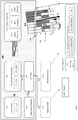
- Fig. 1 is a block diagram illustrating a guidance system 100 according to an embodiment of the present invention.
- the guidance system 100 is configured and operable to carry out the operations of the method described above and further described in more detail below, to remotely guide a remote platform 170 towards a target destination by transmitting optical beam LB carrying guidance information to the remote platform 170.
- the guidance system 100 includes a light module comprising a light source 110, such as a laser (e.g. infrared laser), and a spatial light modulator (SLM) 120, such as a liquid crystal based modulator (e.g. LCoS) and/or digital mirror device (DMD) and/or MEMS scanning mirror.
- a light source 110 such as a laser (e.g. infrared laser)
- SLM spatial light modulator
- LCoS liquid crystal based modulator
- DMD digital mirror device
- the optical beam LB is generated as follows: the light source 110 generates a source optical beam ILB.
- the SLM 120 is positioned in an optical path of the optical beam LB and is adapted and operated to modulate the optical beam to form a modulated optical beam MLB patterned with pattern PT encoding desired information in the beam.
- the system 100 also includes an optical assembly 130 operable for adjusting the shape and/or direction of the optical beam LB.
- the optical assembly may be placed along the optical path of the beam LB before or after SLM 120 and/or it may be distributed along the optical path before and after the SLM 120. Accordingly the optical assembly may form the optical beam OLB output from the system 100 such that it has desired shape and divergence angle.
- the optical beam LB exists in an optical output portion 138 of the guidance system 100 from which it propagates in free space in the direction of one or more remote platforms 170 (a single platform is depicted in the figure).
- the optical beam LB propagating to the platform 170 is therefore modulated/patterned by the SLM 120 to encode desired guidance information and is shaped by the optical module to have desired shape, divergence (collimation degree), and/or direction.
- the system 100 may also include a stabilization module 150, including for example inertial sensors (e.g. gyros and/or accelerometers built-in the system 100 ) and/or other suitable stabilization monitoring modules (e.g. external stabilization monitoring modules), capable of monitoring movements of the system 100 (e.g.
- the controller 140 may be adapted to obtain the stabilization data SD (e.g. sensed by said inertial sensors) and use it when operating the SLM to spatially stabilize the pattern PT which is formed thereby, and to thereby compensate for the movements of the system 100.
- the stabilization data SD e.g. sensed by said inertial sensors
- system 100 includes a controller 140 configured and operable for obtaining data indicative of guidance information for navigating the remote platform 170 towards the target destination 180.
- the target destination 180 may be a target location, to which the platform should reach, and/or a target path to which the motion path of the platform should converge, or a target object to which the platform should be directed.
- the controller is configured and operable to operate the SLM 120 to encode the guidance information in a light pattern PT in the optical beam LB and thereby enable the platform 170 to navigate to the target 180 by detecting at least a cross-sectional region (e.g.
- the system 100 may optionally include or be associated with a target tracking system 152 (target tracker), such as a radar, a satellite based positioning system, a camera, a tracking device installed on the target 180, and or any other suitable tracking system which is capable of monitoring the position/path of the target 180 and providing communicating data indicative of the same to the controller 140.
- a target tracking system 152 target tracker
- the system 100 may generally also include or be associated with a platform tracking system 154 (platform tracker), which may also be a radar, a satellite based positioning system, a camera, a tracking device installed on the platform 170 , and or any other suitable tracking system capable of monitoring the position/path of the platform 180 and providing communicating data indicative of the same to the controller 140 .
- platform tracking system 154 platform tracker
- Each of the target tracker 152 and the platform tracker 154 may be included in the system 100 and/or it may be located remotely from the system.
- the controller may communicate with the target tracker 152 and the platform tracker 154 to obtain respectively obtain target and platform positioning data TD and PD indicative of the respective positions and possibly also velocities of the target 180 and platform 170.
- the controller 140 may process this data TD and/or PD to determine guidance information for the platform 170 (e.g. a course along which to direct/navigate/guide the platform 170 towards the target 180 ).
- the controller 140 is adapted to operate said SLM 120 to encode the guidance information by patterning the optical beam LB with pattern PT.
- the pattern PT may be a spatial pattern formed in a cross-section of said beam, and/or a temporal light pattern formed in the light beam.
- the platform 170 is equipped with a guidance detection module 171 adapted to be furnished on the platform.
- the guidance detection module includes an optical sensor 172 adapted to detect at least a portion of the optical beam LB, and control unit 174 connectable to the sensor 172 and adapted to identify at least a portion (e.g.
- the platform generally also includes steering modules 176 , and the control unit 174 is adapted to operate the steering modules 176 in accordance with the determined navigation instructions so that the platform is steered to the target.
- the sensor module 172 may include a single light sensitive pixel/detector or a few pixels and may be exposed to only a fraction (e.g. PPT 2 ) of the cross-section of the optical beam LB .
- the control unit 174 connectable to the sensor 174 may identify and decode at least one of a spatial and temporal pattern in detected fraction PPT 2 of optical beam, to determine the navigation instructions.
- the optical beam LB is encoded with a spatial pattern defining a plurality of cross-sectional regions, R 1 to R n , in the light beam cross-section wherein each region is modulated temporally or spatially to form therein respective fractions PPT 1 to PPT n of the pattern PT.
- the SLM is operated to define/scale the cross-sectional regions, R 1 - R n , of the light beam such that when any one of them (e.g. R 2 ) impinge on the sensor 172 of the platform 170 its lateral dimensions W are generally substantially wider than the width and height dimensions of the sensor 172 (according to some embodiments of the present invention the lateral dimensions W are substantially wider by one or more orders of magnitude than the platform itself and/or are in the order of/greater than a minimal nominal distance allowed between adjacent co-driven platforms, such that the optical beam can be used to simultaneously navigate a plurality of co-driven platforms to the target).
- the sensor 172 is exposed substantially to only one of the cross-sectional regions of the light beam.
- the light in each cross-sectional region (e.g. R 2 ) of the plurality of cross-sectional regions R 1 to R n in the optical beam LB is modulated (temporally and/or spatially) by the SLM 120 to form therein a respective portion (e.g. PPT 2 ) of the pattern PT of the light beam.
- the respective portion PPT 2 of the pattern is spatially/temporally modulated to encode data indicative of navigation instructions to navigate a platform 170 exposed to this portion PPT2 towards the target 180.
- this data includes at least location data LD indicative of the location of its respective cross-sectional region of the portion PPT 2 with respect to a certain reference position CP (e.g. the center) within the cross-section of the pattern PT that is defined in the beam LB.
- a certain reference position CP e.g. the center
- the reference position CP is considered at the center of the pattern PT, although it may generally be set to any other position.
- control unit 174 obtains from the sensor 172 sensory data/signals indicative of the portion (e.g. PPT 2 ) captured/sensed by the sensor, and processes/decodes this data to determine the location data LD encoded in the sensed portion PPT 2 of the pattern PT.
- the location data LD may be indicative of one or two dimensional displacements (in arbitrary units, for example in units of distance or unitless) between the cross-sectional region (e.g. R 2 ) at which the pattern portion (e.g. PPT 2 ) is encoded and the reference position is CP.
- control unit 174 utilizes coding reference data/relation RD (e.g. a lookup-table (LUT) and/or a function stored for example in a memory associated with the controller 174 ), to decode the portion (e.g. PPT 2 ) of the pattern received by the sensor 172 and determine therefrom the location data LD indicating the position of that portion within the pattern PT, and/or directly determining the steering/navigation instructions based on the identified pattern and the reference data.
- the reference data may be a LUT associating various possible patterns which can be identified by the control-unit 174 with corresponding guidance instructions indicated in these patterns, and/or with their respective displacement from the reference position CP.
- control unit 174 decoding the portion PPT 2 of the pattern may use the LUT to directly determine the steering instructions, or it may use the LUT to determine the location data and further process the location data LD to determine steering instructions to navigate the platform 170 to the target 180 based on the displacement indicated by the location data LD.
- the one or two dimensional displacements may be indicative of the one or two dimensional steering instructions.
- the controller may be adapted to continuously steer the platform so as to minimize the displacement between the cross-sectional-region/pattern it receives by the sensor and the reference position CP, and thereby navigate the platform 170 to the target.
- the location data encoded in the portion PPT 2 of the pattern may indicate a one dimensional displacement from the reference position CP in the pattern PT.
- the platform is driven within a three dimensional volume (e.g.
- the control unit 174 respectively determines guidance/steering instructions to operate the one/two dimensional steering modules 176 of the platform 170.
- Certain embodiments of the invention are designed to operate for navigating remote platforms 170 located at long distances (e.g. in the order of kilometers) from the system 100.
- This poses several issues relating to location of the pattern PT within the beam BL and the size/lateral-width/height Sz of the pattern PT projected by the system (and the sizes of its respective cross-sectional regions R 1 -R n ), when they reach the remote platform 170, and how to optimize/manage these parameters under constraints associated with the movement stability of the system 100 (e.g. changes in position and/or orientation of the light beam BL output from the optical output 138 ) and the divergence of the optical beam LB to allow accurate and reliable detection and identification of the correct pattern portion (e.g. PPT 2 ) by the platform 170 so that the correct navigation/guidance instructions are decoded by the platform 170.
- the correct pattern portion e.g. PPT 2
- the optical beam LB is projected with a suitable cross-sectional width/diameter and/or with a suitable divergence angle such that when it reaches the remote platform 170 the pattern portions PPT 1 - PPT n of the pattern PT carried by the beam LB are each sufficiently wide laterally (e.g. their respective cross-sectional regions R 1 - R n of the beam LB are wide enough) so even tolerable stabilization constraints of the system 100, and the sensor of the platform 170 remain mostly covered/illuminated by the same cross-sectional regions (e.g. R 2 ), thus the mostly constantly "seen" same/correct pattern portion (e.g. PPT 2 ), when decoded, provides the correct guidance/steering information to guide the platform to the target 180.
- a suitable cross-sectional width/diameter and/or with a suitable divergence angle such that when it reaches the remote platform 170 the pattern portions PPT 1 - PPT n of the pattern PT carried by the beam LB are each
- the system 100 may be exposed to vibrations and/or movements and/or rotations which induce deviations in the beam's direction.
- the system may include mechanical stabilization assemblies such as gimbal-based stabilization configured to at least partially stabilize the beam BL.
- mechanical stabilization systems are typically cumbersome and also in some cases do not provide full compensation and stabilization over the beam's movement.
- ⁇ is the desired tolerance to the actual/residual angular deviations of the beam BL, which is obtained after the beam BL, is stabilized by mechanical stabilizers and/or in cases where the beam is not stabilized mechanically.
- Ls is to about ⁇ 1.75 meters (which is 1kM times Tan(0.1°)).
- the lateral dimensions of the pattern portion PPT 2 when reaching the platform 170 should be in the order of (e.g. twice or more) the size/lateral dimensions of the lateral/sideway shifting of the pattern due to the vibrations/movement of the system 100.
- the size/width W of each of the pattern portions PPT 1 - PPT n should be about 3.5 meters or more when reaching the platform.
- the entire pattern PT formed in the optical beam LB includes at least a few such pattern portions (e.g. KxL pattern portions) and its lateral extent Sz is even wider when it reaches the platform 170 .
- the system 100 may include an optical assembly 130 adjusting the beam LB properties (width and/or divergence and/or shape) before it exits the optical output 138 and propagates in free space to the platform 170 .
- the optical assembly 130 may include a beam expander 134 adjusting the width of the beam LB outputted from the optical output 138 to a desired width, and/or it may include a beam collimator 132 adjusting the divergence of the beam LB outputted from the optical output 138 .
- the beam expander 134 and/or the beam collimator 132 are configured and operable to adjust the shape of the beam such that the cross-sectional regions R 1 - R n reach the platform with sufficient width, allowing the platform to detect and decode their respective pattern portions PPT 1 - PPT n .
- the beam expander may be adapted to expand the light beam LB such that its cross-sectional width, when it reaches the platform, is substantially greater, by one or more orders of magnitude, from lateral dimensions of a sensor 172 mounted on the platform 170 .
- the beam expander 134 and/or the beam collimator 132 may be static optical modules having fixed optical properties and/or they may be controllable/adjustable modules, whose optical properties can be controlled by the controller 140 , for example in accordance with the distance of the platform from the system and the required stability tolerance of the system 100 (e.g. the latter may be dynamically determined by the controller 140 by monitoring the rate and/or magnitude of the system's vibrations/movements for example by receiving stabilization data SD indicative of changes in position and/or orientation of the light beam BL the stabilization module 150 ).
- the controller may manipulate/modify the pattern projected by the SLM so as to compensate for a need to optically adjust the width and/or collimation of the beam by the beam expander 134 and/or collimator 132 and thereby enable to obviate the need to use controllably adjustable beam expander 134 and/or beam collimator 132.
- Such manipulations of the pattern projected by the SLM are described in more detail below.
- the optical assembly 130 may be configured to output the light beam LB such that it is un-collimated and divergent when propagating to the platform.
- This provides that the optical output 138 may remain compact (e.g. with a radius in the order of centimeters) while the cross-section of the beam LB becomes sufficiently wide (e.g. in the order of meters or more) when reaching the platform 170 so that the platform decodes its information reliably.
- the controller 140 is configured and operable to manipulate the pattern PT projected by the SLM so as to improve the system's accuracy in navigating the platform 170 to the target 180.
- the platform may be directed to the target with distance accuracy matching/corresponding to the lateral dimensions W of the pattern portions PPT 1 - PPT n (namely corresponding to the lateral dimensions of the pattern portion the platform detects). This is because the guidance instructions cannot be received by the platform 170 with spatial resolution higher that the resolution of the pattern portions encoding them.
- one of the objectives of manipulating the pattern PT by the controller is to reduce the size/lateral dimensions W of the pattern portions reaching the platform, thereby improving the spatial resolution of the pattern portions, and accordingly the spatial resolution of the navigation instructions towards the target 180.
- the size Sz of the pattern PT and accordingly of its constituent pattern portions PPT 1 - PPT n are restricted from below by stabilization constraints/tolerances that the system 100 should endure, and by the fact that optical beam LB is typically made divergent (not collimated) in order to facilitate compactness of the system 100 therefore resulting in the beam's cross-section and accordingly the spatial lateral dimensions of the pattern PT carried thereby, diverging/growing as the platform 170 advances towards the target and its distance from the system 100 grows.
- the controller is adapted to manipulate the pattern projected by the SLM 120 to digitally compensate for movement of the system 100, and thereby allow projection of smaller pattern PT including smaller pattern portions PPT 1 - PPT n .
- the pattern PT is projected with fixed position with respect the beam axis OX, (e.g. for example in case the reference position CP of the pattern is fixed on the beam axis OX ) this will result in corresponding shifting of the pattern by the same magnitude of lateral/sideways deviations.
- the controller 140 is connectable to the stabilization module 150 and is adapted to receiving, therefrom, stabilization data SD indicative of the movement of the system 100.
- the controller processes the stabilization data to estimate the lateral shift in the position of the beam axis from its nominal position at the distance/location of the platform 170, and utilizes the estimated lateral shift of the beam axis to determine how to modify the pattern projected by the SLM to at least partially compensate for such a lateral shift.
- the raw diameter/pupil of the beam that is produced by the light source 110 and passed through the SLM 120, as well as the SLM 120 itself are wider than the actual width of the spatial pattern that is formed in the SLM 120 to filter the beam LB. Accordingly, the controller 140 receiving the stabilization data SD may shift the pattern formed by the SLM to at least partially compensate for motions/vibrations of the system.
- the diameters of the beams LB (the diameter of the raw beam should be denoted without considering the spatial filtering effect of the SLM) and of the PT as a function of distance Z from the system 100 by d R (Z) and d P (Z) respectively.
- the optical axis OX of the beam LB will be shifted sideways (e.g. vibrations of the system 100) by about ⁇ 8.7 meters. That is more than sufficient to compensate and tolerate vibrations up to ⁇ .
- the controller 140 obtains optical path data (not specifically illustrated in the figure) including at least one of:
- the controller 140 may be connectable to the stabilization module 150 to receive therefrom data indicative of the actual displacement of the optical axis OX of the beam BL from its nominal position. Denoting such data for example by the angle ⁇ ', the controller is adapted to modify the pattern PT projected by the SLM so as to compensate for the displacement ⁇ ' in the beam axis. Considering the above calculations, providing such correction may be achieved for example by laterally shifting the pattern in the SLM 120 to counteract and compensate the angular shift ⁇ ' in the optical axis OX.
- the SLM is operated to provide dynamic digital stabilization of the pattern that is projected by the beam thereby enabling to totally obviate mechanical beam stabilization assemblies and/or the SLM may be used to further improve mechanical stabilization provided by less accurate mechanical stabilization assemblies which are less cumbersome.
- the pattern in the SLM is also shifted in accordance with changes in the position of the target 180 so as to navigate the platform 170 to the target 180 while the latter moves.
- the platform 170 may obtain the target's position from the target tracker 152 and operate the SLM 120 to laterally shift the pattern formed thereby by a lateral shift Sft corresponding to the change in the target's position, such that the platform 170 will sense a different pattern portion indicative of the correct navigation instructions towards the target.
- the shift Sft in this case may be integer multiples of at least half the lateral dimension of the pattern portions PPTs so that the platform is exposed to a different pattern portion carrying different navigation instructions matching the location of the target 180.
- Figs. 2A and 2B, and Figs. 2C and 2D exemplify illustratively, in a self explanatory manner, how changing/shifting the position of the pattern PT in the SLM 110 is used according to some embodiments of the present invention to compensate the unstable angular shifts (e.g. vibrations) of the optical axis OX (general light propagation axis) of the beam BL from its nominal position with shift angle ⁇ .
- the same reference numerals are used in these figures to denote objects similar to those described above with reference to Fig. 1 .
- Figs. 2B and 2D are perspective views of a beam BL directed from the optical output 138 of system 100 to platform 170.
- Figs. 2A and 2B correspond respectively to Figs. 2B and 2D , and show the patterns PT formed by the SLM 110 according to the present invention in cases where the optical axis OX is in its nominal position, and in case it deviates from its nominal position by the angle ⁇ .
- the edges of the beam ILB impinging the SLM 110 are illustrated on the SLM 100 in a dashed circular line. It should be noted that pixels of the SLM which are outside the pattern PT may be darkened/opaque so that no light from the beam IBL is emitted (they traverse the SLM) except for the light of the pattern PT. As illustrated in Fig. 2A , when the optical axis is in its nominal position, the controller may operate the SLM 110 to form the pattern PT at its center. Accordingly the pattern is centered about the optical axis OX. As shown in Fig.
- the controller 140 may operate the SLM 110 to form the pattern PT at shifted position, shifted with respect to the center C of the SLM 110 by lateral shift Sft as indicated above.
- the pattern PT projected in this case towards the platform is not centered about the optical axis OX; however the shift Sft is selected such that the reference point CP in the pattern PT reaching towards the platform, maintains the same position as that of Fig. 2A . Accordingly the deviation ⁇ of the optical axis is compensated and a platform position at the same place in figures 2B and 2D will see the same pattern portion and thus will decode the same navigation instructions, although the optical axis OX might have been shifted.
- the platform 170 may be directed to the target 180 with lateral accuracy matching/corresponding to the lateral dimensions of the respective pattern portion it sees (e.g. PPT 2 ) when reaching the target 180.
- the size Sz i.e. lateral dimensions(s) of the projected pattern portion captured by the platform 170 is proportional to Sz ⁇ 2Z*Tan( ⁇ ) (namely it grows linearly with the distance Z by the factor Z *Tan( ⁇ )).
- the controller manipulates the size Sz of the captured pattern portion in accordance with the distance Z of the platform (e.g. in order to maintain the size Sz substantially constant as the platform pattern approaches the target, or even to reduce the size Sz when the platform approaches the target in order to improve guidance accuracy).
- the controller 140 is adapted to obtain distance data indicative of a distance Z between the platform 170 and the system 100 (e.g.
- adjusting the scale of the pattern PT may be achieved by carrying out one or both of the following operations:
- the distance Z may be obtained by the controller 140 from the platform tracker 154 monitoring the platform's location and/or from any other suitable distance measurement system, such as known in the art laser based distance measurement modules (e.g. such as a laser range finder (LRF)).
- LRF laser range finder
- Figs. 2A and 2B, and Figs. 2E and 2E exemplify illustratively, in a self explanatory manner, how changing the scaling factor SF according to operation (ii) above, is used according to some embodiments of the present invention to adjust the size Sz of the pattern (and the sizes of the pattern portions/regions) perceived by the platform.
- the size Sz may be adjusted by the controller in order to preserve the accuracy of the navigation (compensate for the changes in the size Sz resulting from the divergence ⁇ of the beam BL ) or in order to improve navigation accuracy (reduce the pattern size Sz ), as the platform approaches the target 180.
- Figs. 2B and 2F are perspective views of a beam BL directed from the optical output 138 of system 100 to platform 170 where the platform is depicted at different, respectively relatively long and relatively short distances Z from optical output 138 of system 100.
- Figs. 2A and 2E are illustrations of the SLM 110 with the patterns PT formed thereon, corresponding to the distances Z of the platform shown in the corresponding Figs. 2B and 2F . For clarity, the edges of the beam ILB impinging the SLM 110 are illustrated on the SLM 100 in dashed circular line. As shown in Figs.
- the pattern PT in the SLM 110 is scaled down as compared to the pattern PT in Figs. 2E and 2F where the distance Z to platform 170 is shorter (and vice versa the pattern in the SLM 110 is called up as the platform 170 gets closer), so that the pattern PT reaching the platform has, in this example, substantially the same size Sz when reaching to the platform 170 located at various distances Z.
- each of the pattern portions PPT 1 - PPT n is modulated by a spatial and/or temporal code encoding data indicative of respective navigation instructions to navigate a platform 170 exposed thereto towards the target 180.
- spatial modulation in each of the pattern portions PPT 1 - PPT n to at least partially encode therein their respective navigation instructions.
- the respective region (for example R2) each corresponding pattern portion (e.g. PPT 2 ) is spatially modulated and thus divided into a plurality of smaller sub-zones (not specifically shown in the figure) in which bits of the information (navigation instructions) of the pattern portion PPT 2 are encoded.
- the lateral dimensions W of each of the pattern portions PPT 1 - PPT n should be typically much larger than the dimensions of the sensor, therefore in cases where spatial modulation is used in the pattern portions, it is incorporated cyclically/repeatedly, so that the sensor can decode the information encoded in the pattern portion even when it sees only a spatial fraction of the pattern portion.
- the sensors detect an edge/boundary between two or more pattern portions (e.g. the boundary between PPT 2 and PPT 3 it may sense sub-zones from the two or more pattern portions and therefore misinterpret the encoded information.
- improved reliability and accuracy of the navigation is obtained by using purely temporal modulation/data (with no spatial light structure) in the regions R 1 - R n encoding in each of the pattern portions PPT 1 - PPT n (and/or possibly by using combined temporal and spatial encoding with relatively large sizes of the spatial sub-zone of the spatial encoding, e.g. such that only a few such zones can fit and be simultaneously captured by the sensor).
- each of the regions R 1 - R n of the pattern portions PPT 1 - PPT n project substantially spatially homogeneous light intensity.
- the controller 140 is adapted to operate the SLM 120 to define spatiotemporal light pattern PT encoding navigation information in the beam BL.
- the spatiotemporal light pattern includes spatial light pattern defining a plurality of spatially distributed cross-sectional regions R 1 - R n within a cross-section of the light beam BL.
- Each cross-sectional region of the regions R 1 - R n is associated with a respective one of the pattern portions PPT 1 - PPT n , and encodes different navigation instructions, via a temporal pattern/modulation of the light therein (e.g. while the light in the region is substantially homogeneous).
- the temporal patterns/modulations in the respective regions R 1 - R n are distinguishable patterns encoding different instructions.
- the temporal patterns may be formed by operating the SLM 120 to temporally modulate the light intensities in these regions R 1 - R n in accordance with the navigation data/instructions to be encoded in each region.
- the distinguishable temporal light patterns may be respectively indicative of locations LD of the cross-sectional regions associated therewith R 1 - R n , with respect to the cross-section of the light beam (e.g. with respect to the reference position CP ).
- This provides reliable encoding and decoding of the guidance information in the beam BL which is less susceptible to un-stabilized movements of the pattern PT (such un-stabilized movement may be a residual un-stabilized motion of the spatial pattern in the beam which may remain even after the beam/pattern are stabilized mechanically by gimbals and/or digitally by properly operating the SLM).
- the temporal patterns/modulations of the spatiotemporal pattern are transmitted repeatedly (e.g. periodically/cyclically) in each of their respective regions R 1 - R n , such that the sensor 172 can quickly detect them at any time.
- the time duration/period of the temporal modulation patterns formed in the pattern portions PPT 1 - PPT n should be shorter than a predetermined minimal/characteristic time interval during which the guidance instructions in any of the pattern portions may change (namely it should be shorter than the time resolution of the provision navigation instruction of the system 100 ) so that in between consecutive navigation information updates of the pattern PT, the sensor 172 of the detection module 170 can identify the temporal light pattern to which it exposed.
- the time duration/period of the temporal modulation should preferably be shorter than characteristic/minimal time between stabilization updates which are used by the controller 140 to stabilize the pattern (by operating the SLM to adjust its lateral position in the beam), so that in between consecutive stabilization related modifications of the pattern PT, the sensor 172 of the detection module 170 can identify the temporal light pattern to which it exposed.
- Figs. 3A and 3B exemplifying two possible spatiotemporal patterns/modulations of the beam LB, which can be used according to some embodiments of the present invention to navigate a platform 170 towards a target 180.
- the pattern is spatially divided into eight cross-sectional regions R 1 - R 8 in the beam BL defining eight respective pattern portions PPT 1 -PPT 8 .
- Fig. 3A is an example of a spatiotemporal pattern PT having one spatial dimension (the regions R 1 - R 8 are distributed in one dimension of the pattern PT ) which is usable for navigating the platform motion on a two dimensional surface (e.g. navigating land based vehicles).
- Fig. 3A is an example of a spatiotemporal pattern PT having one spatial dimension (the regions R 1 - R 8 are distributed in one dimension of the pattern PT ) which is usable for navigating the platform motion on a two dimensional surface (e.g. navigating land based vehicles).
- 3B is an example of a spatiotemporal pattern PT having two spatial dimensions which is usable for navigating the platform motion in three dimensional space (e.g. navigation aerial platforms).
- the pattern portions PPT 1 -PPT 8 in the regions R 1 - R 8 are distinct from each other and are defined by respectively different/distinguishable temporal modulations of the optical beam in these regions.
- the spatiotemporal pattern PT in this example is formed by three temporal frames FR1-FR3. Each of the temporal frames shown in the figures depicts the spatial distribution of the regions R 1 - R 8 in the pattern PT and their state (transparent/opaque lit/darkened in the SLM 110 ).
- the controller 140 operates to the SLM 110 to present these frames in a sequence (the frames may or may not extend to similar time durations) to project the spatiotemporal pattern PT in the light beam BL.
- the SLM state in the regions R 1 - R 8 in the frames are set such that distinctive temporal light patterns are formed in the regions R 1 - R 8 when these frames are sequentially presented by the SLM in the optical path of the beam BL.
- the SLM is operated to form a binary light pattern with dark/opaque regions presenting for example bit up (binary 1) and lit regions presenting bit down (binary 0).
- log 2 (n) frames are required. It should be understood that other (e.g. non-binary) intensity modulation schemes may also be applicable in the present invention enabling to reduce the number of temporal frames needed to define a desired number of distinct regions.
- I_FR initialization frames
- the initialization frames may present a similar light pattern/state in each of the regions so that the guidance detection module 171 can identify them easily, disregarding to which region of the regions R1- R 8 they are exposed to. Also the initialization frames may actually include a plurality of predetermined initialization frames presented in a sequence defining an initialization code. The latter may optionally be encrypted to encrypt the guidance beam BL of the system 100.
- Fig. 3C specifying and depicting in a self explanatory manner the temporal light sequences (modulation patterns) including the initialization frame/bit which are shown in each of the pattern portions PPT 1 -PPT 8 presented respectively in the spatial cross-sectional regions R 1 -R 8 . Also, the interpretation of these temporal sequences into corresponding numerical binary codes indicative of the regions in which they are presented, are shown in the table.
- the control unit may determine which region it sees (e.g. R 2 ) and thereby determine the correct navigation instructions towards the target 180.
- At least parts of codes presented in the temporal modulation patterns/sequences of each of the pattern portions encode data indicative of the direction of the target 180 with respect to the platform 170.
- this data may actually be indicative of the location of the cross-sectional regions R 1 -R 8 at the respective temporal modulation patterns with respect to a certain reference location CP in the pattern PT (e.g. the center thereof).
- other parts of the codes encode additional data associated with the guidance of the platform towards the target.
- an additional data piece included/encoded in the code may be indicative of a degree of convergence of motion path of the platform 170 towards the target 180. That is, the code provides both the direction to the target 180 and also indicates how fast the platform should turn towards this direction. This allows navigating the platform 170 to the target 180 along non-linear paths (e.g. a parabolic path) which may be useful in some scenarios.
- non-linear paths e.g. a parabolic path
- the cross-section of the pattern PT in the light beam reaching the platform 170 is substantially larger than the dimensions of the platform. For example it may be one or two orders of magnitude larger than the lateral dimensions of the platform.
- the pattern PT may be used to simultaneously guide the plurality of platforms towards the target 180.
- the system 100 simultaneously guides the plurality of platforms, encoding the additional data piece indicative of a degree of convergence of motion path of the pattern portion encoding that data is useful as it enables to avoid collisions between the plurality of co-guided platforms approaching the target. This is because it permits directing the plurality of platforms with no linear/parabolic paths to the target, such that the pluralities of platforms meet only in the vicinity of the target.
- the guidance detection module 171 which is mounted on the platform 170 as illustrated in Fig. 1 , it includes the optical sensor 172 adapted to at least partially detect light from at least one cross-sectional region (e.g. R 2 of the light beam LB ) and a control unit 174 which is connected to the sensor 172 and to the steering modules of the platform 170.
- the control unit 174 is adapted to process the data/signals that are captured by the sensor 172 and to identify the respective pattern portion (e.g. the temporal modulation pattern of the pattern portion PPT 2 ) modulating the light in the region (e.g. R 2 ) to which the sensor is exposed.
- the control unit 174 decodes the detected pattern portion PPT 2 to determine at least the direction of the target with respect to the platform and thereby determine the navigation instructions, and accordingly operate the steering modules of said platform to direct the platform towards the target.
- pattern portions PPT 1 -PPT n are spatially homogenous temporal patterns (whose spatial dimension is larger relative to sensor of the platform 170 ), therefore the sensor 172 in such embodiments need not be able to discern spatial details and may therefore include even only one light sensitive pixel (indeed sensors with more pixels are still useable, and the additional pixels may provide failsafe redundancy).
- the lateral dimensions of the light sensitive pixel of the sensor 172 are substantially smaller than lateral dimensions of each of the regions R 1 -R n . Accordingly, the light sensitive pixel of the sensor sense the temporal light modulation pattern of substantially a single region. This enables determining the temporal light modulation pattern accurately and unambiguously.
- the sensor's pixels are operated with integration time / a frame rate that is shorter (e.g. by one or more orders of magnitude) than the duration of the temporal modulation pattern.
Landscapes
- Engineering & Computer Science (AREA)
- Chemical & Material Sciences (AREA)
- Combustion & Propulsion (AREA)
- General Engineering & Computer Science (AREA)
- Physics & Mathematics (AREA)
- Optical Radar Systems And Details Thereof (AREA)
- Computer Networks & Wireless Communication (AREA)
- General Physics & Mathematics (AREA)
- Radar, Positioning & Navigation (AREA)
- Remote Sensing (AREA)
- Optical Communication System (AREA)
- Electromagnetism (AREA)
- Traffic Control Systems (AREA)
Claims (21)
- Führungssystem (100) zur entfernten Führung von mindestens einer entfernten Plattform (170) zu einem Zielort, wobei das Führungssystem Folgendes umfasst: ein Lichtmodul, das eine Lichtquelle (110) umfasst, die zum Emittieren eines Lichtstrahls konfiguriert ist, einen optischen Ausgangsabschnitt (130), der dafür konfiguriert ist, den genannten Lichtstrahl auf die genannte Plattform zu richten, und eine Steuereinheit (140), die dafür konfiguriert und betreibbar ist, Daten zu erhalten, die Führungsinformationen zum Navigieren der genannten entfernten Plattform zu dem genannten Ziel angeben;
wobei das Führungssystem einen räumlichen Lichtmodulator (120) (Spatial Light Modulator, SLM) umfasst, der in einem optischen Pfad des Lichtstrahls angeordnet ist, der von der genannten Lichtquelle (110) emittiert wird, und dafür konfiguriert und betätigbar ist, ein raumzeitliches Muster innerhalb eines Querschnitts des Lichtstrahls durch dynamisches Umschalten zwischen verschiedenen programmierbaren räumlichen Mustern zu bilden, und
wobei die genannte Steuereinheit (140) dafür konfiguriert und betreibbar ist, den genannten SLM (120) zu betreiben, um den Querschnitt des Lichtstrahls räumlich und zeitlich zu modulieren, um die genannten Führungsinformation im raumzeitlichen Muster in Form mehrerer räumlich verteilter Querschnittsbereiche innerhalb des Querschnitts des genannten Lichtstrahls zu codieren, die jeweils darin unterscheidbare zeitliche Lichtmuster aufweisen, wodurch die Navigation der genannten Plattform (170) zum Ziel hin ermöglicht wird, indem mindestens ein Querschnittsbereich des genannten Lichtstrahls erfasst und ein Teil der genannten Führungsinformationen, die in der genannten Querschnittsregion des genannten Lichtstrahls codiert sind, decodiert wird, um Führungsbefehle zum Navigieren der genannten mindestens einen entfernten Plattform (170) zu dem genannten Zielbestimmungsort zu bestimmen. - Führungssystem nach Anspruch 1 wobei die genannten unterscheidbaren zeitlichen Lichtmuster entsprechende Führungsbefehle zum Navigieren der entfernten Plattform in Richtung des genannten Zielortes anzeigen, wenn sie einem der genannten zeitlichen Lichtmuster ausgesetzt sind.
- Führungssystem nach einem der vorhergehenden Ansprüche wobei die genannten Führungshinweise durch Folgendes bestimmt werden:- Erfassen von Licht von mindestens einem der genannten Querschnittsbereiche des Lichtstrahls;- Identifizieren eines jeweiligen zeitlichen Modulationsmusters, das die genannten Querschnittsbereiche des Lichtstrahls moduliert, wodurch der genannte Teil der Führungsinformation decodiert wird; und- Bestimmen der genannten Führungsbefehle basierend auf dem genannten jeweiligen zeitlichen Modulationsmuster.
- Führungssystem nach Anspruch 3 wobei die genannten unterscheidbaren zeitlichen Lichtmuster jeweils Orte der dort zugeordneten Querschnittsbereiche in Bezug auf den genannten Querschnitt des Lichtstrahls anzeigen, wobei das Bestimmen der genannten Führungsbefehle das Verwenden des genannten jeweiligen zeitlichen Modulationsmusters umfasst, um einen Ort eines Querschnittsbereichs innerhalb des genannten Querschnitts des Lichtstrahls zu bestimmen und die genannten Führungsbefehle basierend auf dem genannten Ort zu bestimmen.
- Führungssystem nach einem der Ansprüche 2 bis 4, wobei das genannte zeitliche Modulationsmuster die genannte Stelle der Querschnittsregion und mindestens ein zusätzliches Datenstück, das sich auf die genannte Führungsinformation bezieht, codiert; und wobei das genannte wenigstens eine zusätzliche Datenstück Daten enthält, die einen Konvergenzgrad des Bewegungspfades der genannten Plattform zu dem genannten Ziel angeben.
- Führungssystem nach einem der vorhergehenden Ansprüche, wobei die genannte Steuereinheit dafür ausgelegt ist, Abstandsdaten zu erhalten, die einen Abstand zwischen der genannten Plattform und dem genannten optischen Ausgang des Führungssystems anzeigen, und Daten zu erhalten, die einen Grad der Kollimation des genannten Lichtstrahls angeben, und den genannten SLM zu betreiben, um eine Skala des genannten räumlichen Lichtmusters basierend auf den genannten Abstandsdaten und dem genannten Kollimationsgrad des Lichtstrahls zu modifizieren, um dadurch die Divergenz des genannten Lichtstrahls zu kompensieren, wenn er sich zu der genannten Plattform ausbreitet.
- Führungssystem nach einem der vorhergehenden Ansprüche, wobei die genannte Steuereinheit dafür ausgelegt ist, optische Pfaddaten zu erhalten, die mindestens eines von Folgendem umfassen:(i) Stabilisierungsdaten, die eine Abweichung eines optischen Pfads des genannten Lichtstrahls von einem nominalen optischen Pfad angeben, entlang dem der genannte Lichtstrahl projiziert werden sollte, um die genannte Plattform zu dem genannten Ziel zu navigieren, und(ii) Zielpositionsdaten, die eine Position des genannten Ziels anzeigen, aus der der genannte nominale optische Pfad bestimmt werden kann; undwobei die genannte Steuereinheit dafür ausgelegt ist, den genannten SLM zu betreiben, um das genannte raumzeitliche Lichtmuster zu modifizieren, indem das genannte raumzeitliche Lichtmuster innerhalb des Querschnitts des Strahls basierend auf den genannten optischen Pfaddaten seitlich verschoben wird, um dadurch für mindestens eine der genannten Abweichungen des optischen Pfades und für Änderungen der genannten Position des Ziels zu kompensieren.
- Führungssystem nach Anspruch 7, das in mindestens einer der Folgenden Arten konfiguriert ist:- das genannte Führungssystem umfasst Trägheitssensoren, wobei die genannte Steuereinheit dafür ausgelegt ist, die genannten Stabilisierungsdaten mindestens teilweise basierend auf der Bewegung des genannten Führungssystems zu erhalten, die von den genannten Trägheitssensoren erfasst wird; und- die genannte Steuereinheit ist einem Verfolgungssensor zugeordnet, der zum Verfolgen des genannten Ziels ausgelegt ist und dafür ausgelegt ist, die genannten Zielpositionsdaten mindestens teilweise beruhend auf der Bewegung oder Position des genannten Ziels zu erhalten, das von den genannten Verfolgungssensoren erfasst wird.
- Führungssystem nach einem der vorhergehenden Ansprüche, das gemäß mindestens einem der Folgenden konfiguriert ist:- der genannte SLM umfasst mindestens eines der Folgenden: eine digitale Mikrospiegelvorrichtung (Micro-Mirror Device, DMD), eine Flüssigkristallvorrichtung (Liquid Crystal Device, LCD) und eine Anordnung von MEMS-Spiegeln;- die genannte Lichtquelle ist eine Laserlichtquelle;- das Führungssystem umfasst eine optische Anordnung, die dafür ausgelegt ist, den genannten Lichtstrahl auf die genannte Plattform zu richten;- das Führungssystem umfasst eine optische Baugruppe, die mindestens eines der Folgenden umfasst: einen Strahlkollimator, der dafür ausgelegt ist, den genannten Lichtstrahl zu kollimieren, und ein Strahlaufweiter, der dafür ausgelegt ist, den genannten Lichtstrahl aufzuweiten, so dass eine Querschnittsbreite des Lichtstrahls, der die genannte Plattform erreicht, um ein oder mehrere Größenordnungen von Seitenabmessungen eines auf der genannten Plattform montierten Lichtdetektors wesentlich größer ist.
- Führungssystem nach einem der vorhergehenden Ansprüche, das ein Führungserfassungsmodul umfasst, das dafür ausgelegt ist, auf der genannten Plattform eingerichtet zu werden; wobei das genannte Führungserfassungsmodul Folgendes umfasst: einen adaptierten optischen Sensor, um mindestens einen Querschnittsbereich des genannten Lichtstrahls zu erfassen, und eine an den genannten Sensor anschließbare und angepasste Steuereinheit, um mindestens eines von einem räumlichen und zeitlichen Muster in dem genannten erfassten mindestens einen Querschnittsbereich zu identifizieren, das genannte Muster zu decodieren, um die darin codierten Navigationsanweisungen zu bestimmen, und Steuermodule der genannten Plattform zu betreiben, um die genannte Plattform gemäß den genannten Navigationsanweisungen auf das genannte Ziel zu richten.
- Führungssystem nach Anspruch 10, wobei das genannte Lichtmuster ein räumlich-zeitliches Muster ist, das in einer Vielzahl von Querschnittsbereichen des genannten Lichtstrahls räumlich verteilt ist, wobei Licht in der genannten Vielzahl von Querschnittsbereichen zeitlich mit jeweiligen unterscheidbaren zeitlichen Modulationsmustern moduliert wird; wobei die genannte Steuereinheit dafür ausgelegt ist, ein zeitliches Modulationsmuster in der erfassten Querschnittsregion zu identifizieren und die genannten Anweisungen basierend auf dem genannten zeitlichen Modulationsmuster zu bestimmen.
- Führungssystem nach Anspruch 11 wobei der genannte Sensor mindestens ein lichtempfindliches Pixel umfasst, das in der Lage ist, das genannte zeitliche Modulationsmuster zu erfassen, das in dem genannten Querschnittsbereich des Lichtstrahls codiert ist; und wobei die lateralen Abmessungen des genannten lichtempfindlichen Pixels wesentlich kleiner sind als die lateralen Abmessungen des genannten Querschnittsbereichs, vorausgesetzt, dass das genannte lichtempfindliche Pixel das genannte zeitliche Lichtmodulationsmuster von im Wesentlichen einer einzigen Querschnittsregion abtastet, wodurch das genannte zeitliche Lichtmodulationsmuster genau und eindeutig bestimmt werden kann.
- Führungssystem nach Anspruch 12, wobei die Dauer des genannten zeitlichen Modulationsmusters wesentlich kürzer ist als ein charakteristisches Zeitintervall zwischen Modifikationen der Position und/oder des Maßstabs des genannten räumlichen Teils des genannten raumzeitlichen Lichtmusters und wobei das genannte lichtempfindliche Pixel mit einer Integrationszeit betrieben wird, die wesentlich kürzer ist als die Dauer des genannten zeitlichen Modulationsmusters.
- Führungssystem nach einem der vorhergehenden Ansprüche, das dafür konfiguriert und ausgelegt ist, den genannten Lichtstrahl zu übertragen, um ihn zu der genannten Plattform mit Querschnittsabmessungen von zwei oder mehr Größenordnungen größer als laterale Abmessungen der genannten Plattform zu übertragen, wodurch eine gleichzeitige Führung einer Vielzahl von Plattformen in Richtung des genannten Ziels ermöglicht wird.
- Führungssystem nach Anspruch 14 wobei das genannte Lichtmuster ein raumzeitliches Muster ist, das Folgendes umfasst: ein räumliches Lichtmuster, das eine Vielzahl von Querschnittsbereichen in einem Querschnitt des genannten Strahls definiert, und zeitliche Lichtmuster, die jeweils in den genannten Bereichen gebildet werden; und wobei ein zeitliches Modulationsmuster in jedem Querschnittsbereich Daten codiert, die eine Richtung des genannten Ziels in Bezug auf eine Plattform anzeigen, die dem genannten Bereich ausgesetzt ist, und mindestens ein zusätzliches Datenstück, das einen gewünschten Konvergenzgrad des Bewegungspfades der Plattform in Richtung des genannten Ziels anzeigt; wobei es das genannte zusätzliche Datenstück ermöglicht, Kollisionen zwischen der genannten Vielzahl von Plattformen zu vermeiden, wenn diese sich dem genannten Ziel nähern.
- Verfahren zur entfernten Führung von mindestens einer entfernten Plattform (170) zu einem Zielort, wobei das Verfahren Folgendes umfasst:- Betreiben einer Lichtquelle (110) zum Erzeugen eines Lichtstrahls zum Beleuchten der genannten entfernten Plattform;- Erhalten von Daten, die Führungsinformationen zum Navigieren der genannten entfernten Plattform zu dem genannten Ziel angeben;- Bereitstellen eines räumlichen Lichtmodulators (120), SLM, der in einem optischen Pfad des genannten Lichtstrahls angeordnet ist, wobei der genannte SLM (120) dafür konfiguriert und ausgelegt ist, ein räumlich-zeitliches Muster innerhalb des Querschnitts des Lichtstrahls durch dynamisches Umschalten zwischen verschiedenen programmierbaren räumlichen Mustern zu bilden; und- Betreiben des genannten SLM (120), um den Querschnitt des Lichtstrahls räumlich und zeitlich zu modulieren, um die genannten Führungsinformationen im raumzeitlichen Muster in Form mehrerer räumlich verteilter Querschnittsbereiche mit jeweils unterscheidbaren zeitlichen Lichtmustern innerhalb des Querschnitts des genannten Lichtstrahls zu codieren, wodurch die Navigation der genannten mindestens einen Plattform (170) zum Ziel ermöglicht wird, indem mindestens ein Querschnittsbereich des genannten Lichtstrahls erfasst und ein Teil der genannten Führungsinformation, die in der genannten Querschnittsregion codiert sind, decodiert wird.
- Verfahren nach Anspruch 16, wobei die genannten unterscheidbaren zeitlichen Lichtmuster gemäß einem oder mehreren von Folgendem konfiguriert sind:- die genannten unterscheidbaren zeitlichen Lichtmuster, die entsprechende Führungsanweisungen zum Navigieren auf der entfernten Plattform in Richtung des genannten Zielortes anzeigen anzeigen, wenn sie einem der genannten zeitlichen Lichtmuster ausgesetzt sind;- die genannten unterscheidbaren zeitlichen Lichtmuster weisen jeweils mindestens auf Orte der ihnen zugeordneten Querschnittsbereiche bezogen auf den genannten Querschnitt des Lichtstrahls hin, und wobei die genannten Führungsanweisungen basierend auf den genannten Positionen bestimmt werden;- die maximale Zeitdauer der genannten unterscheidbaren zeitlichen Modulationsmuster ist kürzer als ein charakteristisches Zeitintervall zwischen aufeinander folgenden Einstellungen der lateralen Position und der Skala des genannten räumlichen Lichtmusters;- das genannte unterscheidbare zeitliche Modulationsmuster codiert mindestens ein zusätzliches Datenstück, das einen gewünschten Grad der Konvergenz des Bewegungspfades der Plattform in Richtung des genannten Ziels anzeigt.
- Verfahren nach einem der Ansprüche 16 oder 17, das Folgendes umfasst:Bereitstellen von Abstandsdaten, die eine Entfernung zu der genannten Plattform angeben, und von Daten, die einen Kollimationsgrad des genannten Lichtstrahls angeben; undBetreiben des genannten SLM, um eine Skala des genannten räumlichen Lichtmusters basierend auf den genannten Entfernungsdaten und dem genannten Grad der Kollimation anzupassen, um die Divergenz des genannten Lichtstrahls zu kompensieren, wenn er sich zu der genannten Plattform ausbreitet.
- Verfahren nach einem der Ansprüche 16 bis 18, das Folgendes umfasst: Bereitstellen von optischen Pfaddaten, die umfassen: mindestens eines von Stabilisierungsdaten, die eine Abweichung eines optischen Pfads des genannten Lichtstrahls von einem nominellen optischen Pfad angeben, auf dem der genannte Lichtstrahl projiziert werden sollte, um die genannte Plattform zu den genannten Ziel zu navigieren, und Zielpositionsdaten, die eine Position des genannten Ziels anzeigen, von dem der genannte nominelle optische Pfad bestimmt werden kann; und Betreiben des genannten SLM, um eine laterale Position des genannten räumlichen Lichtmusters innerhalb des Querschnitts des Lichtstrahls basierend auf den genannten optischen Pfaddaten einzustellen, um dadurch mindestens eine der genannten Abweichungen des optischen Pfades und Änderungen in der genannten Position des Ziels zu kompensieren.
- Verfahren nach einem der Ansprüche 16 bis 19, wobei die genannten lateralen Querschnittsabmessungen des genannten Lichtstrahls zwei oder mehr Größenordnungen größer sind als die lateralen Abmessungen der genannten Plattform, wodurch eine gleichzeitige Führung einer Vielzahl von Plattformen in Richtung des genannten Ziels ermöglicht wird.
- Verfahren nach einem der Ansprüche 16 bis 20, das die Bestimmung der genannten Führungsanweisungen bei der genannten Plattform durch Folgendes umfasst:- Erfassen von Licht von mindestens einem der genannten Querschnittsbereiche des Lichtstrahls;- Identifizieren eines jeweiligen zeitlichen Modulationsmusters, das die genannten Querschnittsbereiche des Lichtstrahls moduliert; und- Decodieren des genannten jeweiligen zeitlichen Modulationsmusters, um den genannten Teil der Führungsinformationen zu bestimmen, die die genannten Führungsbefehle anzeigen.
Applications Claiming Priority (2)
| Application Number | Priority Date | Filing Date | Title |
|---|---|---|---|
| IL236338A IL236338B (en) | 2014-12-18 | 2014-12-18 | Guidance system and method |
| PCT/IL2015/051208 WO2016098103A1 (en) | 2014-12-18 | 2015-12-13 | Guidance system and method |
Publications (2)
| Publication Number | Publication Date |
|---|---|
| EP3234492A1 EP3234492A1 (de) | 2017-10-25 |
| EP3234492B1 true EP3234492B1 (de) | 2019-01-30 |
Family
ID=55236830
Family Applications (1)
| Application Number | Title | Priority Date | Filing Date |
|---|---|---|---|
| EP15828668.2A Active EP3234492B1 (de) | 2014-12-18 | 2015-12-13 | Führungssystem und -verfahren |
Country Status (6)
| Country | Link |
|---|---|
| US (1) | US10677565B2 (de) |
| EP (1) | EP3234492B1 (de) |
| BR (1) | BR112017012602A2 (de) |
| IL (1) | IL236338B (de) |
| SG (1) | SG11201704930QA (de) |
| WO (1) | WO2016098103A1 (de) |
Families Citing this family (6)
| Publication number | Priority date | Publication date | Assignee | Title |
|---|---|---|---|---|
| US20190249394A1 (en) * | 2016-10-28 | 2019-08-15 | Husqvarna Ab | A demolition robot control device and system |
| CN111284662A (zh) * | 2018-12-07 | 2020-06-16 | 中国科学院沈阳自动化研究所 | 一种应用于水下机器人自主回收的光源引导系统 |
| IL263768A (en) * | 2018-12-17 | 2020-06-30 | Shilat Optronics Ltd | Laser-guided attach drone for targts with no line sight |
| RU2704675C1 (ru) * | 2019-04-11 | 2019-10-30 | Акционерное общество "Научно-технический центр ЭЛИНС" | Устройство формирования оптического поля для телеориентирования управляемых объектов |
| US11624588B2 (en) | 2020-06-25 | 2023-04-11 | Simmonds Precision Products, Inc. | Coded aperture seeker for navigation |
| KR102685089B1 (ko) * | 2021-12-09 | 2024-07-15 | (주)아울링크 | 지대공 비행 유도 장치 |
Family Cites Families (25)
| Publication number | Priority date | Publication date | Assignee | Title |
|---|---|---|---|---|
| GB1315351A (en) | 1963-05-10 | 1973-05-02 | Eltro Gmbh | Method and apparatus for determining co-ordinates |
| FR1466437A (fr) * | 1965-12-06 | 1967-01-20 | Csf | Système optique de guidage d'un projectile |
| DE2533697A1 (de) | 1975-07-28 | 1977-02-03 | Precitronic | Einrichtung zur signaluebertragung zwischen einer abschussbasis und einem flugkoerper mittels einer lichtuebertragungsstrecke |
| JPS5842431B2 (ja) * | 1975-12-29 | 1983-09-20 | 富士重工業株式会社 | 飛翔体の光ビ−ム誘導装置 |
| GB1524122A (en) * | 1976-01-29 | 1978-09-06 | Elliott Brothers London Ltd | Guidance systems for mobile craft |
| US4243187A (en) | 1978-05-01 | 1981-01-06 | Mcdonnell Douglas Corporation | Missile director with beam axis shift capability |
| FR2441145A1 (fr) * | 1978-11-09 | 1980-06-06 | Aerospatiale | Systeme de guidage pour tir en rafale de missiles telecommandes |
| US4299360A (en) * | 1979-01-30 | 1981-11-10 | Martin Marietta Corporation | Beamrider guidance technique using digital FM coding |
| US5533692A (en) | 1979-01-30 | 1996-07-09 | Oerlikon-Contraves Ag | Beamrider guidance system using digital phase modulation encoding |
| DE2951941C2 (de) * | 1979-12-22 | 1988-01-21 | Diehl GmbH & Co, 8500 Nürnberg | Optische Fernlenkvorrichtung für ein Geschoß |
| FR2474681A1 (fr) * | 1980-01-29 | 1981-07-31 | Telecommunications Sa | Systeme de guidage d'engin par faisceau lumineux |
| DE3117685C2 (de) * | 1981-05-05 | 1983-08-18 | Diehl GmbH & Co, 8500 Nürnberg | Einrichtung zur Erzeugung eines Lenkstrahls |
| US5560567A (en) | 1983-09-06 | 1996-10-01 | Loral Vought Systems Corporation | Passive missile tracking and guidance system |
| FR2559252B2 (fr) * | 1984-02-07 | 1986-12-05 | Cilas Alcatel | Dispositif laser pour guider un missile sur une cible |
| ES2019870B3 (es) * | 1986-01-30 | 1991-07-16 | Werkzeugmaschinenfabrik Oerlikon-Buhrle Ag | Dispositivo para guiar una particula volatil. |
| US4732349A (en) * | 1986-10-08 | 1988-03-22 | Hughes Aircraft Company | Beamrider guidance system |
| FR2627269B1 (fr) * | 1988-02-17 | 1993-05-14 | Thomson Csf | Systeme de correction de la trajectoire d'un projectile |
| DE4416211C2 (de) * | 1994-05-07 | 1996-09-26 | Rheinmetall Ind Gmbh | Verfahren und Vorrichtung zur Flugbahnkorrektur von Geschossen |
| DE4425285C2 (de) * | 1994-07-16 | 1997-04-17 | Rheinmetall Ind Ag | Vorrichtung zur Flugbahnkorrektur von drallstabilisierten Geschossen |
| EP1702197B1 (de) * | 2003-12-22 | 2013-05-22 | Eyepoint Ltd. | Hochpräzises elektrooptisches weitwinkel-positionierungssystem und verfahren |
| US8386096B2 (en) * | 2009-12-22 | 2013-02-26 | General Electric Company | Relative navigation system |
| US8872081B2 (en) | 2011-11-01 | 2014-10-28 | Ge Aviation Systems Llc | Methods for adjusting a relative navigation system |
| US9012822B2 (en) * | 2012-07-18 | 2015-04-21 | Thales Holdings Uk Plc | Missile guidance |
| US9170435B2 (en) * | 2013-03-12 | 2015-10-27 | Ge Aviation Systems Llc | Method of forming a grid defining a first relative reference frame |
| US9121709B2 (en) * | 2013-03-12 | 2015-09-01 | Ge Aviation Systems, Llc | Method of forming a grid defining a first relative reference frame |
-
2014
- 2014-12-18 IL IL236338A patent/IL236338B/en active IP Right Grant
-
2015
- 2015-12-13 US US15/536,619 patent/US10677565B2/en active Active
- 2015-12-13 EP EP15828668.2A patent/EP3234492B1/de active Active
- 2015-12-13 BR BR112017012602-8A patent/BR112017012602A2/pt not_active Application Discontinuation
- 2015-12-13 WO PCT/IL2015/051208 patent/WO2016098103A1/en not_active Ceased
- 2015-12-13 SG SG11201704930QA patent/SG11201704930QA/en unknown
Non-Patent Citations (1)
| Title |
|---|
| None * |
Also Published As
| Publication number | Publication date |
|---|---|
| BR112017012602A2 (pt) | 2018-01-16 |
| US20180245882A1 (en) | 2018-08-30 |
| EP3234492A1 (de) | 2017-10-25 |
| IL236338B (en) | 2018-12-31 |
| US10677565B2 (en) | 2020-06-09 |
| SG11201704930QA (en) | 2017-07-28 |
| WO2016098103A1 (en) | 2016-06-23 |
Similar Documents
| Publication | Publication Date | Title |
|---|---|---|
| US10677565B2 (en) | Guidance system and method | |
| CA2832956C (en) | System and method for controlling an unmanned aerial vehicle | |
| US20150241562A1 (en) | Laser navigation system and method | |
| EP3168704B1 (de) | 3d überwachung einer fläche durch mobile fahrzeuge | |
| EP2112456B1 (de) | Vorrichtung und Verfahren für ein Visier | |
| US9758239B2 (en) | System and method for controlling an unmanned air vehicle | |
| KR102065521B1 (ko) | 로봇의 이동 경로의 레이저 조사를 제어하는 서버와 방법 및 이에 기반하여 이동하는 로봇 | |
| US10324183B2 (en) | UAV measuring apparatus and UAV measuring system | |
| ES2341291T3 (es) | Arquitectura de adquisicion, apunte y seguimiento para comunicaciones con laser. | |
| US8463463B1 (en) | Methods for formation flying aided by a relative navigation system | |
| JP6114851B2 (ja) | 相対ナビゲーションシステムの状況認識情報を提供するためのシステムおよび方法 | |
| ES2524416T3 (es) | Técnica para transmitir simultáneamente señales de baliza óptica ancha y estrecha | |
| EP3469741B1 (de) | Optische kommunikationsvorrichtung | |
| KR102005100B1 (ko) | 소형 지상 레이저 표적 지시기 | |
| ES2927401T3 (es) | Procedimiento para la alineación de un rayo láser emitido desde un transmisor de comunicación óptica con una estación receptora | |
| EP3047228B1 (de) | Bildgestützte beleuchtungsanordnung und verfahren | |
| GB2590956A (en) | Guidance head and method | |
| US7175130B2 (en) | Missile steering using laser scattering by atmosphere | |
| EP3258623A1 (de) | Optische kommunikationsvorrichtung | |
| KR20210122155A (ko) | 통합 퓨전 센서 장치 | |
| US7150428B2 (en) | Beam laser atmospheric scattering trajectory guidance | |
| JPS6048511A (ja) | 移動体の誘導ならびに通信装置 | |
| RU2729336C1 (ru) | Способ управления беспилотным летательным аппаратом малого класса | |
| KR102041195B1 (ko) | 자유 공간 광 통신 장치 및 방법 | |
| EP4684483A1 (de) | Optische drahtlose kommunikationsvorrichtung |
Legal Events
| Date | Code | Title | Description |
|---|---|---|---|
| STAA | Information on the status of an ep patent application or granted ep patent |
Free format text: STATUS: THE INTERNATIONAL PUBLICATION HAS BEEN MADE |
|
| PUAI | Public reference made under article 153(3) epc to a published international application that has entered the european phase |
Free format text: ORIGINAL CODE: 0009012 |
|
| STAA | Information on the status of an ep patent application or granted ep patent |
Free format text: STATUS: REQUEST FOR EXAMINATION WAS MADE |
|
| 17P | Request for examination filed |
Effective date: 20170718 |
|
| AK | Designated contracting states |
Kind code of ref document: A1 Designated state(s): AL AT BE BG CH CY CZ DE DK EE ES FI FR GB GR HR HU IE IS IT LI LT LU LV MC MK MT NL NO PL PT RO RS SE SI SK SM TR |
|
| AX | Request for extension of the european patent |
Extension state: BA ME |
|
| DAV | Request for validation of the european patent (deleted) | ||
| DAX | Request for extension of the european patent (deleted) | ||
| GRAP | Despatch of communication of intention to grant a patent |
Free format text: ORIGINAL CODE: EPIDOSNIGR1 |
|
| STAA | Information on the status of an ep patent application or granted ep patent |
Free format text: STATUS: GRANT OF PATENT IS INTENDED |
|
| INTG | Intention to grant announced |
Effective date: 20180702 |
|
| GRAS | Grant fee paid |
Free format text: ORIGINAL CODE: EPIDOSNIGR3 |
|
| GRAA | (expected) grant |
Free format text: ORIGINAL CODE: 0009210 |
|
| STAA | Information on the status of an ep patent application or granted ep patent |
Free format text: STATUS: THE PATENT HAS BEEN GRANTED |
|
| AK | Designated contracting states |
Kind code of ref document: B1 Designated state(s): AL AT BE BG CH CY CZ DE DK EE ES FI FR GB GR HR HU IE IS IT LI LT LU LV MC MK MT NL NO PL PT RO RS SE SI SK SM TR |
|
| REG | Reference to a national code |
Ref country code: GB Ref legal event code: FG4D |
|
| REG | Reference to a national code |
Ref country code: CH Ref legal event code: EP |
|
| REG | Reference to a national code |
Ref country code: AT Ref legal event code: REF Ref document number: 1093630 Country of ref document: AT Kind code of ref document: T Effective date: 20190215 |
|
| REG | Reference to a national code |
Ref country code: IE Ref legal event code: FG4D |
|
| REG | Reference to a national code |
Ref country code: DE Ref legal event code: R096 Ref document number: 602015024196 Country of ref document: DE |
|
| REG | Reference to a national code |
Ref country code: LT Ref legal event code: MG4D |
|
| REG | Reference to a national code |
Ref country code: NL Ref legal event code: MP Effective date: 20190130 |
|
| PG25 | Lapsed in a contracting state [announced via postgrant information from national office to epo] |
Ref country code: NO Free format text: LAPSE BECAUSE OF FAILURE TO SUBMIT A TRANSLATION OF THE DESCRIPTION OR TO PAY THE FEE WITHIN THE PRESCRIBED TIME-LIMIT Effective date: 20190430 Ref country code: FI Free format text: LAPSE BECAUSE OF FAILURE TO SUBMIT A TRANSLATION OF THE DESCRIPTION OR TO PAY THE FEE WITHIN THE PRESCRIBED TIME-LIMIT Effective date: 20190130 Ref country code: NL Free format text: LAPSE BECAUSE OF FAILURE TO SUBMIT A TRANSLATION OF THE DESCRIPTION OR TO PAY THE FEE WITHIN THE PRESCRIBED TIME-LIMIT Effective date: 20190130 Ref country code: SE Free format text: LAPSE BECAUSE OF FAILURE TO SUBMIT A TRANSLATION OF THE DESCRIPTION OR TO PAY THE FEE WITHIN THE PRESCRIBED TIME-LIMIT Effective date: 20190130 Ref country code: PT Free format text: LAPSE BECAUSE OF FAILURE TO SUBMIT A TRANSLATION OF THE DESCRIPTION OR TO PAY THE FEE WITHIN THE PRESCRIBED TIME-LIMIT Effective date: 20190530 Ref country code: PL Free format text: LAPSE BECAUSE OF FAILURE TO SUBMIT A TRANSLATION OF THE DESCRIPTION OR TO PAY THE FEE WITHIN THE PRESCRIBED TIME-LIMIT Effective date: 20190130 Ref country code: LT Free format text: LAPSE BECAUSE OF FAILURE TO SUBMIT A TRANSLATION OF THE DESCRIPTION OR TO PAY THE FEE WITHIN THE PRESCRIBED TIME-LIMIT Effective date: 20190130 Ref country code: ES Free format text: LAPSE BECAUSE OF FAILURE TO SUBMIT A TRANSLATION OF THE DESCRIPTION OR TO PAY THE FEE WITHIN THE PRESCRIBED TIME-LIMIT Effective date: 20190130 |
|
| REG | Reference to a national code |
Ref country code: AT Ref legal event code: MK05 Ref document number: 1093630 Country of ref document: AT Kind code of ref document: T Effective date: 20190130 |
|
| PG25 | Lapsed in a contracting state [announced via postgrant information from national office to epo] |
Ref country code: RS Free format text: LAPSE BECAUSE OF FAILURE TO SUBMIT A TRANSLATION OF THE DESCRIPTION OR TO PAY THE FEE WITHIN THE PRESCRIBED TIME-LIMIT Effective date: 20190130 Ref country code: HR Free format text: LAPSE BECAUSE OF FAILURE TO SUBMIT A TRANSLATION OF THE DESCRIPTION OR TO PAY THE FEE WITHIN THE PRESCRIBED TIME-LIMIT Effective date: 20190130 Ref country code: LV Free format text: LAPSE BECAUSE OF FAILURE TO SUBMIT A TRANSLATION OF THE DESCRIPTION OR TO PAY THE FEE WITHIN THE PRESCRIBED TIME-LIMIT Effective date: 20190130 Ref country code: GR Free format text: LAPSE BECAUSE OF FAILURE TO SUBMIT A TRANSLATION OF THE DESCRIPTION OR TO PAY THE FEE WITHIN THE PRESCRIBED TIME-LIMIT Effective date: 20190501 Ref country code: IS Free format text: LAPSE BECAUSE OF FAILURE TO SUBMIT A TRANSLATION OF THE DESCRIPTION OR TO PAY THE FEE WITHIN THE PRESCRIBED TIME-LIMIT Effective date: 20190530 Ref country code: BG Free format text: LAPSE BECAUSE OF FAILURE TO SUBMIT A TRANSLATION OF THE DESCRIPTION OR TO PAY THE FEE WITHIN THE PRESCRIBED TIME-LIMIT Effective date: 20190430 |
|
| PG25 | Lapsed in a contracting state [announced via postgrant information from national office to epo] |
Ref country code: EE Free format text: LAPSE BECAUSE OF FAILURE TO SUBMIT A TRANSLATION OF THE DESCRIPTION OR TO PAY THE FEE WITHIN THE PRESCRIBED TIME-LIMIT Effective date: 20190130 Ref country code: DK Free format text: LAPSE BECAUSE OF FAILURE TO SUBMIT A TRANSLATION OF THE DESCRIPTION OR TO PAY THE FEE WITHIN THE PRESCRIBED TIME-LIMIT Effective date: 20190130 Ref country code: IT Free format text: LAPSE BECAUSE OF FAILURE TO SUBMIT A TRANSLATION OF THE DESCRIPTION OR TO PAY THE FEE WITHIN THE PRESCRIBED TIME-LIMIT Effective date: 20190130 Ref country code: RO Free format text: LAPSE BECAUSE OF FAILURE TO SUBMIT A TRANSLATION OF THE DESCRIPTION OR TO PAY THE FEE WITHIN THE PRESCRIBED TIME-LIMIT Effective date: 20190130 Ref country code: CZ Free format text: LAPSE BECAUSE OF FAILURE TO SUBMIT A TRANSLATION OF THE DESCRIPTION OR TO PAY THE FEE WITHIN THE PRESCRIBED TIME-LIMIT Effective date: 20190130 Ref country code: AL Free format text: LAPSE BECAUSE OF FAILURE TO SUBMIT A TRANSLATION OF THE DESCRIPTION OR TO PAY THE FEE WITHIN THE PRESCRIBED TIME-LIMIT Effective date: 20190130 Ref country code: SK Free format text: LAPSE BECAUSE OF FAILURE TO SUBMIT A TRANSLATION OF THE DESCRIPTION OR TO PAY THE FEE WITHIN THE PRESCRIBED TIME-LIMIT Effective date: 20190130 |
|
| REG | Reference to a national code |
Ref country code: DE Ref legal event code: R097 Ref document number: 602015024196 Country of ref document: DE |
|
| PG25 | Lapsed in a contracting state [announced via postgrant information from national office to epo] |
Ref country code: SM Free format text: LAPSE BECAUSE OF FAILURE TO SUBMIT A TRANSLATION OF THE DESCRIPTION OR TO PAY THE FEE WITHIN THE PRESCRIBED TIME-LIMIT Effective date: 20190130 |
|
| PLBE | No opposition filed within time limit |
Free format text: ORIGINAL CODE: 0009261 |
|
| STAA | Information on the status of an ep patent application or granted ep patent |
Free format text: STATUS: NO OPPOSITION FILED WITHIN TIME LIMIT |
|
| PG25 | Lapsed in a contracting state [announced via postgrant information from national office to epo] |
Ref country code: AT Free format text: LAPSE BECAUSE OF FAILURE TO SUBMIT A TRANSLATION OF THE DESCRIPTION OR TO PAY THE FEE WITHIN THE PRESCRIBED TIME-LIMIT Effective date: 20190130 |
|
| 26N | No opposition filed |
Effective date: 20191031 |
|
| PG25 | Lapsed in a contracting state [announced via postgrant information from national office to epo] |
Ref country code: SI Free format text: LAPSE BECAUSE OF FAILURE TO SUBMIT A TRANSLATION OF THE DESCRIPTION OR TO PAY THE FEE WITHIN THE PRESCRIBED TIME-LIMIT Effective date: 20190130 |
|
| PG25 | Lapsed in a contracting state [announced via postgrant information from national office to epo] |
Ref country code: TR Free format text: LAPSE BECAUSE OF FAILURE TO SUBMIT A TRANSLATION OF THE DESCRIPTION OR TO PAY THE FEE WITHIN THE PRESCRIBED TIME-LIMIT Effective date: 20190130 |
|
| REG | Reference to a national code |
Ref country code: CH Ref legal event code: PL |
|
| REG | Reference to a national code |
Ref country code: BE Ref legal event code: MM Effective date: 20191231 |
|
| PG25 | Lapsed in a contracting state [announced via postgrant information from national office to epo] |
Ref country code: MC Free format text: LAPSE BECAUSE OF FAILURE TO SUBMIT A TRANSLATION OF THE DESCRIPTION OR TO PAY THE FEE WITHIN THE PRESCRIBED TIME-LIMIT Effective date: 20190130 |
|
| PG25 | Lapsed in a contracting state [announced via postgrant information from national office to epo] |
Ref country code: IE Free format text: LAPSE BECAUSE OF NON-PAYMENT OF DUE FEES Effective date: 20191213 Ref country code: LU Free format text: LAPSE BECAUSE OF NON-PAYMENT OF DUE FEES Effective date: 20191213 |
|
| PG25 | Lapsed in a contracting state [announced via postgrant information from national office to epo] |
Ref country code: CH Free format text: LAPSE BECAUSE OF NON-PAYMENT OF DUE FEES Effective date: 20191231 Ref country code: BE Free format text: LAPSE BECAUSE OF NON-PAYMENT OF DUE FEES Effective date: 20191231 Ref country code: LI Free format text: LAPSE BECAUSE OF NON-PAYMENT OF DUE FEES Effective date: 20191231 |
|
| PG25 | Lapsed in a contracting state [announced via postgrant information from national office to epo] |
Ref country code: CY Free format text: LAPSE BECAUSE OF FAILURE TO SUBMIT A TRANSLATION OF THE DESCRIPTION OR TO PAY THE FEE WITHIN THE PRESCRIBED TIME-LIMIT Effective date: 20190130 |
|
| PG25 | Lapsed in a contracting state [announced via postgrant information from national office to epo] |
Ref country code: MT Free format text: LAPSE BECAUSE OF FAILURE TO SUBMIT A TRANSLATION OF THE DESCRIPTION OR TO PAY THE FEE WITHIN THE PRESCRIBED TIME-LIMIT Effective date: 20190130 Ref country code: HU Free format text: LAPSE BECAUSE OF FAILURE TO SUBMIT A TRANSLATION OF THE DESCRIPTION OR TO PAY THE FEE WITHIN THE PRESCRIBED TIME-LIMIT; INVALID AB INITIO Effective date: 20151213 |
|
| PG25 | Lapsed in a contracting state [announced via postgrant information from national office to epo] |
Ref country code: MK Free format text: LAPSE BECAUSE OF FAILURE TO SUBMIT A TRANSLATION OF THE DESCRIPTION OR TO PAY THE FEE WITHIN THE PRESCRIBED TIME-LIMIT Effective date: 20190130 |
|
| PGFP | Annual fee paid to national office [announced via postgrant information from national office to epo] |
Ref country code: DE Payment date: 20251126 Year of fee payment: 11 |
|
| PGFP | Annual fee paid to national office [announced via postgrant information from national office to epo] |
Ref country code: GB Payment date: 20251120 Year of fee payment: 11 |
|
| PGFP | Annual fee paid to national office [announced via postgrant information from national office to epo] |
Ref country code: FR Payment date: 20251124 Year of fee payment: 11 |