EP3469741B1 - Optische kommunikationsvorrichtung - Google Patents
Optische kommunikationsvorrichtung Download PDFInfo
- Publication number
- EP3469741B1 EP3469741B1 EP17731253.5A EP17731253A EP3469741B1 EP 3469741 B1 EP3469741 B1 EP 3469741B1 EP 17731253 A EP17731253 A EP 17731253A EP 3469741 B1 EP3469741 B1 EP 3469741B1
- Authority
- EP
- European Patent Office
- Prior art keywords
- optical signal
- optical
- vehicle
- volume
- water
- Prior art date
- Legal status (The legal status is an assumption and is not a legal conclusion. Google has not performed a legal analysis and makes no representation as to the accuracy of the status listed.)
- Active
Links
Images


Classifications
-
- H—ELECTRICITY
- H04—ELECTRIC COMMUNICATION TECHNIQUE
- H04B—TRANSMISSION
- H04B10/00—Transmission systems employing electromagnetic waves other than radio-waves, e.g. infrared, visible or ultraviolet light, or employing corpuscular radiation, e.g. quantum communication
- H04B10/11—Arrangements specific to free-space transmission, i.e. transmission through air or vacuum
- H04B10/112—Line-of-sight transmission over an extended range
- H04B10/1123—Bidirectional transmission
-
- G—PHYSICS
- G02—OPTICS
- G02B—OPTICAL ELEMENTS, SYSTEMS OR APPARATUS
- G02B26/00—Optical devices or arrangements for the control of light using movable or deformable optical elements
- G02B26/08—Optical devices or arrangements for the control of light using movable or deformable optical elements for controlling the direction of light
- G02B26/10—Scanning systems
- G02B26/12—Scanning systems using multifaceted mirrors
- G02B26/127—Adaptive control of the scanning light beam, e.g. using the feedback from one or more detectors
-
- H—ELECTRICITY
- H04—ELECTRIC COMMUNICATION TECHNIQUE
- H04B—TRANSMISSION
- H04B10/00—Transmission systems employing electromagnetic waves other than radio-waves, e.g. infrared, visible or ultraviolet light, or employing corpuscular radiation, e.g. quantum communication
- H04B10/11—Arrangements specific to free-space transmission, i.e. transmission through air or vacuum
- H04B10/112—Line-of-sight transmission over an extended range
-
- H—ELECTRICITY
- H04—ELECTRIC COMMUNICATION TECHNIQUE
- H04B—TRANSMISSION
- H04B10/00—Transmission systems employing electromagnetic waves other than radio-waves, e.g. infrared, visible or ultraviolet light, or employing corpuscular radiation, e.g. quantum communication
- H04B10/80—Optical aspects relating to the use of optical transmission for specific applications, not provided for in groups H04B10/03 - H04B10/70, e.g. optical power feeding or optical transmission through water
-
- H—ELECTRICITY
- H04—ELECTRIC COMMUNICATION TECHNIQUE
- H04B—TRANSMISSION
- H04B13/00—Transmission systems characterised by the medium used for transmission, not provided for in groups H04B3/00 - H04B11/00
- H04B13/02—Transmission systems in which the medium consists of the earth or a large mass of water thereon, e.g. earth telegraphy
Definitions
- the present invention relates to optical communication devices.
- a FSO communication system typically consists of a pair of nodes or communication devices. Each node typically comprises an optical source, for example a laser or light emitting diode (LED), and an optical receiver. In use, the optical source of each node is aligned with the optical receiver of the other node. Modulation of optical signals emitted by the optical sources allows for the bidirectional transfer of data between the two nodes. Thus, there is a datalink between the nodes.
- an optical source for example a laser or light emitting diode (LED)
- LED light emitting diode
- Gbps Giga-bits per second
- Radio Frequency (RF) signals tends to be heavily attenuated by seawater, and hence the range of RF communications systems tends to be severely limited.
- Acoustic systems can offer low data rate transmission ( ⁇ kbps) over long ranges, but are typically overt which is undesirable for certain applications.
- Optical communications systems have also been developed for underwater applications. Such underwater optical communications systems tend to provide relatively high data rate communications over short to medium ranges, for example up to a 300m or so.
- an underwater optical communication system typically comprises a pair of nodes, each node will comprising an optical source and detector.
- each node will comprising an optical source and detector.
- underwater modes tend to be mobile.
- the position of each node, and hence the range and angular separation between the nodes is not fixed.
- alignment between opposing optical sources and detectors tends to be required in order for the communications system to function.
- many underwater nodes are unmanned nodes (e.g. unmanned vehicle), and hence manual alignment between a pair of nodes tends not to be possible.
- each underwater node may have some estimate of the relative location of the opposing underwater node (e.g. a pre-programmed location and navigation using GPS/inertial systems, or through use of a separate data link) there may be a large range and angular uncertainty in its position.
- the present inventors have realised that it would be beneficial for optical communication nodes or devices to be able to reliably and accurately acquire the location of the opposing node, for example, before beam alignment and optical communications occur.
- the present inventors have further realised that it would be beneficial for nodes to be capable of active beam alignment (i.e. tracking) during data transfer, particularly for mobile nodes.
- the present inventors have further realised that using an optical beam with large divergence, for example to illuminate the area surrounding the transmitting node to ensure that the other each node receives some optical power, tends to be very power inefficient since most of the transmitted optical power does not reach the detector of the opposing node.
- the present inventor have realised that such a strategy tends to only be suitable in clean water and/or at short range.
- the present inventors have further realised that using a lens to focus the transmitted light to produce a focussed "spot" on the communications detector tends to be highly dependent on angle of incidence of the incoming light. Thus, large incidence angles may result in all or part of the spot being displaced from the centre of the communications detector, thereby reducing the communication link margin.
- each node in a pair of nodes may comprise an angle of arrival (AoA) light sensor.
- a first of the nodes may scan a narrow light beam across the angular search area.
- the light beam from the first node is incident on the AoA sensor of the second node, thereby allowing the second node to infer the angular location of the first node.
- the second node may then direct a narrow light beam towards the inferred location of the first node.
- the AoA sensor of the first node may then detect the beam from the second node, and, using measurements of the beam, infer the location of the second node.
- the first node may then stop scanning, and direct its narrow light beam in the inferred location of the second node. Communications between the nodes may then begin.
- scanning a large angular search area with a narrow beam may take significant amount of time.
- acquiring the communication link tends to use increased time and/or power.
- the present inventors have further realised that the link margin may not be known (for example, since the water conditions and/or the range between nodes may not be known).
- the present inventors have realised it would be beneficial to provide a system and method that overcome the above mentioned deficiencies of using optical beams having large divergence and also the above mentioned deficiencies of using narrow/collimated optical beams.
- the present invention provides a method of transmitting an optical signal by a Free Space Optical, FSO, communication system.
- the method comprises: transmitting, by an optical signal transmitter, a first optical signal towards a vehicle present within a volume of water, such that the optical signal covers a given search area in the volume of water; and in response to not receiving an incident optical signal from the vehicle after transmitting the first optical signal; transmitting, by the optical signal transmitter, a second optical signal into the volume of water, the second optical signal having a reduced beam divergence than the first optical signal; and controlling, by a controller, the optical signal transmitter, to scan the volume of water using the second optical signal having the second beam divergence in a sequence of non-overlapping closed loops wherein each of the sequence of non-overlapping closed loops crosses itself at least once.
- the controller controls the transmitter such that at least part of the transmitter moves along a path that defines a loop, i.e. a path that crosses itself at least once. For example, when scanning the volume, the controller controls the transmitter to move along a path that has its start point the same point as its end point.
- a path over a plane onto which the optical signal is projected defines a plurality non-overlapping loops on that plane, i.e. a plurality of non-overlapping paths, each having their start points be the same as their end points.
- Each of loops in the sequence may be a substantially circular loop.
- the step of controlling may comprise controlling the optical signal transmitter to scan the at least part of the volume by repeating at least part of one or more of the loops at least twice. At least part of one or more of the loops may be repeated at least twice. At least part of one or more of the loops may be repeated at most twice. At least part of one or more of the loops may be repeated exactly twice.
- Transmitting the optical signal may comprise: generating an optical signal; modifying a divergence and an irradiance of the generated optical signal such that at least one of the divergence and the irradiance is equal to a preselected value; and transmitting the modified optical signal.
- the method may further comprise: transmitting, by the optical signal transmitter or a further optical signal transmitter, a further optical signal into at the least part of the volume, the further optical signal having a different beam divergence and irradiance than the optical signal; and controlling, by a controller, the optical signal transmitter or the further optical signal transmitter, to scan the at least part of the volume using the further optical signal in a further sequence of non-overlapping loops.
- the method may further comprise: responsive to transmitting the optical signal into the at least part of the volume, receiving, by an optical signal detector, a response optical signal; and determining, using measurements of the response optical signal by the optical signal detector, by one or more processors, a location of a source of the response optical signal.
- a field of view of the optical signal transmitter may be directed in a same direction as a field of view of the optical signal detector.
- the method may further comprise: the FSO communication system transmits a location signal wherein the location signal at least operates to enable the source of the response optical signal to identify the position of the FSO communication system.
- the location signal may be transmitted in substantially the same direction as the field of view of the optical signal detector. This may be to enable the source of the response optical signal to use the location signal to manoeuvre to a position where effective communication may be performed, for example, the bit error rate of a communication signal is at an acceptable level for the current mission. Manoeuvring may be required due to while the source of the response signal has identified the position of the FSO communication system, the communication signal levels may be too low to achieve the required communication data rate between the FSO communication system and the source of the response signal.
- the location signal may act as a beacon and may undertake Identification Friend or Foe (IFF) so that the FSO communication system may avoid an unknown acquisition or a known undesirable acquisition.
- IFF Identification Friend or Foe
- the location signal is preferably an optical location signal.
- the location signal may be an acoustic signal, which may have a greater range than an optical signal.
- the optical medium may be water.
- the present invention comprises a Free Space Optical, FSO, communication system comprising: an optical signal transmitter configured to transmit a first optical signal towards a vehicle within a volume of water such that the optical signal covers a given search area in the volume of water; and a processor configured to determine whether an optical signal detector has received an incident optical signal from the vehicle after transmitting the first optical signal; and in response to not receiving an incident optical signal; the optical signal transmitter configured to transmit a second optical signal into the volume of water, the second optical signal having reduced divergence than the first optical signal; and a controller configured to control the optical signal transmitter to scan the volume of water using the second optical signal having the second beam divergence in a sequence of non-overlapping closed loops wherein each of the sequence of non-overlapping closed loops crosses itself at least once.
- the sequence of non-overlapping loops may be a sequence of non-overlapping, concentric circular loops.
- the controller may be further configured to scan the at least part of the volume by repeating at least part of one or more of the loops at least twice.
- the FSO communication system may further comprise an optical signal detector configured to, responsive to the optical signal transmitter transmitting the optical signal into the at least part of the volume, receive a response optical signal.
- the FSO communication system may further comprise one or more processors configured to determine, using measurements of the response optical signal by the optical signal detector, a location of a source of the response optical signal.
- a field of view of the optical signal transmitter may be directed in a same direction as a field of view of the optical signal detector.
- the present invention comprises a vehicle comprising an FSO communication system according to any preceding aspect.
- the vehicle may be a submersible vehicle.
- Figure 1 is a schematic illustration (not to scale) showing an example vehicle 100 in which an embodiment of an optical communications system 102 is implemented.
- the vehicle 100 is an unmanned, submersible (or underwater) vehicle, i.e. a vehicle that is configured to operate while submerged, for example, in water.
- the optical communications system 102 comprises an optical signal transmitter 104, an optical signal detector 106, and a processor 108.
- the optical signal transmitter 104 is configured to transmit an optical signal (such as a laser beam) from the vehicle 100, as described in more detail later below with reference to Figures 2 to 9 .
- the optical signal transmitter 104 comprises an optical signal generator 110 and lens 112.
- the optical signal generator 110 is configured to generate an optical signal, and send the generated optical signal to the lens 112 for transmission from the vehicle 110.
- the optical signal generator 110 may comprise, for example, a laser or light emitting diode (LED).
- the optical signal generator 110 may be configured to modulate the generated optical signals to encode data.
- the lens 112 is arranged to focus the generated optical signal from optical signal generator 110, and direct the focussed optical signal away from the vehicle 100.
- the lens 112 is controllable to vary the divergence of the transmitted optical signal.
- the lens 502 may be a translating lens, a zoom lens, a fluidic lens, a programmable liquid crystal lens, or a programmable holographic lens (such as a switchable Bragg Element or a Digilens).
- the lens 502 is controlled by the processor 108.
- the optical signal transmitter 104 is operatively coupled to the processor 108 such that the processor 108 may control operation of the optical signal transmitter 104, i.e. of the optical signal generator 110 and the lens 112.
- the optical signal detector 106 is configured to detect an optical signal (such as a laser beam) incident on the optical signal detector 106, and to generate an output corresponding to the received optical signal.
- the optical signal detector 106 comprises an Angle of Arrival (AoA) sensor having a relatively narrow Field of View (FoV).
- the optical signal detector 106 is operatively coupled to the processor 108 such that the processor 108 may receive an output of the optical signal detector 106.
- the processor 108 is configured to process the received output of the of the optical signal detector 106 as described in more detail later below with reference to Figure 2 .
- the optical signal transmitter 104 is steerable such that the direction, relative to the vehicle 100, in which an optical signal is transmitted by the optical signal transmitter 104 may be varied. Thus, an optical signal transmitted by the optical signal transmitter 104 may be scanned over an area.
- the steering of the optical signal transmitter 104 is controlled by the processor 108.
- the optical signal detector 106 is steerable such that the FoV of the optical signal detector 106 may be varied. The steering of the optical signal detector 106 is controlled by the processor 108.
- the optical signal transmitter 104 and the optical signal detector 106 may be steered in any appropriate way.
- the optical signal transmitter 104 and/or the optical signal detector 106 are mounted to a pan/tilt unit which is controlled by the processor 108.
- one or more steering mirrors is used to steer the optical signal transmitter 104 and/or the optical signal detector 106.
- the one or more steering mirrors may be controlled by the processor 108.
- the optical signal transmitter 104 and the optical signal detector 106 are directed in substantially the same direction.
- Apparatus including the processor 108, for implementing the above arrangement, and performing the method steps to be described later below, may be provided by configuring or adapting any suitable apparatus, for example signal amplifiers, one or more computers or other processing apparatus or processors, and/or providing additional modules.
- the apparatus may comprise a computer, a network of computers, or one or more processors, for implementing instructions and using data, including instructions and data in the form of a computer program or plurality of computer programs stored in or on a machine readable storage medium such as computer memory, a computer disk, ROM, PROM etc., or any combination of these or other storage media.
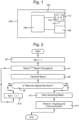
- Figure 2 is a process flow chart showing certain steps of an embodiment of an optical communications process.
- the optical communications process by which the submersible vehicle 100 communicates in an underwater environment with a further submersible vehicle.
- the optical communications process comprises iteratively performing steps s4 to s8.
- the iteration index i is indicative of an iteration number of the process.
- the processor 108 selects a value for the divergence of the ith light beam to be transmitted from the vehicle 100.
- the value for the divergence of the first light beam to be transmitted from the vehicle 100 is selected to be as large as possible, i.e. the largest possible beam divergence that is achievable by the lens 112.
- the processor 108 controls the optical signal transmitter 104 to transmit a light beam having the selected beam divergence.
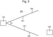
- the vehicle 100 transmits the first light beam in a direction of the further vehicle 300, through an optical medium 302 which, in this embodiment, is water (for example, seawater).
- an optical medium 302 which, in this embodiment, is water (for example, seawater).
- the first light beam is indicated in Figure 3 by two solid arrows and the reference numeral 304.
- the first light beam 304 is bounded by these arrows.
- the first light beam 304 has a divergence of ⁇ 1 , where ⁇ 1 is the maximum divergence achievable by the optical signal transmitter 104.
- the first light beam 304 substantially covers the entirety of a search area or search volume, which is indicated in Figure 3 by dotted lines and the reference numeral 306.
- the search area 306 is an area in which the vehicle 300 is to transmit light beam to attempt to establish a communications link with the further vehicle 300.
- the search area 306 is defined by the value ⁇ 1 .
- the further vehicle 300 comprises an optical communications system capable of detecting optical signals incident on the further vehicle 300, and further configured to transmit optical signals.
- the further vehicle may comprise the optical communications system 102 described in more detail earlier above with reference to Figure 1 .
- the communications conditions are such that an optical detector on board the further vehicle 300 does not receive sufficient power from the first light beam 304 to enable it to detect the first light beam 304.
- the first light beam 304 is attenuated by the water 302 to such a degree that, in effect, the first light beam 304 is not received by the further vehicle 300.
- the further vehicle 300 does not detect the light beam transmitted by the vehicle, the further vehicle 300 does not transmit a response optical signal towards the vehicle 100.
- the communications conditions may be more favourable and such that the wide first beam 304 is received and detected by the optical detector of the further vehicle 300.
- the further vehicle will transmit a response signal back to the vehicle 100, which is received at the vehicle 100, as described in more detail later below with reference to Figure 8 .
- the processor 108 determines whether or not the optical signal detector 106 has detected an incident optical signal. In particular, in this embodiment, the processor 108 determines whether or not the optical signal detector 106 has detected a response optical signal from the further vehicle 100.
- step s8 the processor 108 determines that the optical signal detector 106 has not detected an incident optical signal, the method proceeds to step s10.
- step s10 the method proceeds back to step s4 for a next iteration of steps s4 to s8.
- step s4 the processor 108 selects successively decreasing values for the divergence of the light beam to be transmitted from the vehicle 100. In other words, in each iteration of step s4, the processor 108 selects a value for the divergence of the light beam that is lower than the value selected in the previous iteration.
- the transmitted light beam will not cover the entirety of the search area 306 at the same time.
- the processor 108 controls the optical signal transmitter 104 to scan the transmitted light beam across all of the search area 306.
- the processor 108 controls the optical signal transmitter 104 to scan the transmitted light beam in a sequence of non-overlapping concentric circles, as described in more detail below with reference to Figures 4 to 7 .
- the power used to generate the light beam is substantially the same for each iteration.
- decreasing the divergence of the light beam increases its irradiance.
- the irradiance of the light beam is higher than the irradiance in the previous iteration.
- the light tends to penetrated through the water 302 to a greater extent, in effect increasing the acceptable attenuation of the signal through the water path.
- the vehicle 100 transmits the second light beam (bounded by solid arrows 500) in a direction of the further vehicle 300, through the optical medium 302.
- the second light beam 500 has a divergence of ⁇ 2 , which, in this embodiment, is equal to ⁇ 1 /3.
- the effective range of the optical communication system 102 is increased.
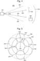
- the second light beam 500 is scanned in a pattern indicated in Figure 4 by arrows and the reference numerals 502 and 504, and described in more detail below with reference to Figure 5 .
- Figure 5 is a schematic illustration (not to scale) showing a scan pattern implemented by the optical communications system 102 to scan the second light beam 500 over the search area 306.
- Figure 5 shows the search area 306 from the point of view of the vehicle 100.
- the search area 306 is substantially circular.
- the search area 306 is scanned as follows.
- the processor 108 controls the optical signal transmitter 104 to transmit a light beam at the centre 600 of the search area 306.
- the optical signal transmitter 104 is centred with respect to the search area 306.
- the processor 108 controls the optical signal transmitter 104 to move its FoV towards the edge of the search area 306 through an angular distance of ⁇ 1 /3 (i.e. the divergence of the light beam 500 in this iteration).
- the optical signal transmitter 104 is centred at point 602 shown in Figure 5 . This movement is indicated in Figure 5 by a straight arrow and the reference numeral 502.
- the processor 108 controls the optical signal transmitter 104 to scan an outer portion of the search area 306 by moving its FoV in a circular loop about the centre 600. This movement is indicated in Figure 5 by an arrow and the reference numeral 504. Thus, an annulus surrounding the scanned central portion is scanned.
- the scanned circular loop 504 does not overlap with the originally scanned central portion.
- scanning of the search area 306 tends to be efficient in term of both time and power.
- the processor 108 controls the optical signal transmitter 104 to scan the circular loop 504 twice. This double scanning of the circular loop advantageously tends to facilitate the detection of a return signal by the vehicle 100, as described in more detail later below.
- the communications conditions are such that an optical detector on board the further vehicle 300 does not receive sufficient power from the second light beam 500 to enable it to detect the second light beam 500.
- the second light beam 500 is attenuated by the water 302 to such a degree that, in effect, the second light beam 500 is not received by the further vehicle 300.
- the vehicle 100 transmits the third light beam (bounded by solid arrows 700) in a direction of the further vehicle 300, through the optical medium 302.
- the third light beam 700 has a divergence of ⁇ 3 , which, in this embodiment, is equal to ⁇ 1 /5.
- the effective range of the optical communication system 102 is increased.
- the third light beam 700 is scanned in a pattern indicated in Figure 6 by arrows and the reference numerals 702-708, and described in more detail below with reference to Figure 7 .
- Figure 7 is a schematic illustration (not to scale) showing a scan pattern implemented by the optical communications system 102 to scan the third light beam 700 over the search area 306.
- Figure 7 shows the search area 306 from the point of view of the vehicle 100.
- the search area 306 is scanned as follows.
- the processor 108 controls the optical signal transmitter 104 to transmit the third light beam 700 at the centre 600 of the search area 306.
- the optical signal transmitter 104 is centred with respect to the search area 306.
- the processor 108 controls the optical signal transmitter 104 to move its FoV towards the edge of the search area 306 through an angular distance of ⁇ 1 /5 (i.e. the divergence of the light beam 500 in this iteration). This movement is indicated in Figure 7 by a straight arrow and the reference numeral 702.
- the optical signal transmitter 104 is centred at point 710 shown in Figure 7 .
- the processor 108 controls the optical signal transmitter 104 to scan an annular portion of the search area 306 by moving its FoV in a circular loop about the centre 600, maintaining the separation between the centre 600 and the transmitted light beam. This movement is indicated in Figure 7 by an arrow and the reference numeral 704.
- an annulus surrounding the scanned central portion is scanned.
- this scanned circular loop 704 does not overlap with the originally scanned central portion.
- scanning of the search area 306 tends to be efficient in term of both time and power.
- the processor 108 controls the optical signal transmitter 104 to scan the circular loop 704 twice.
- the processor 108 controls the optical signal transmitter 104 to move its FoV towards the edge of the search area 306 through an angular distance of ⁇ 1 /5 (i.e. the divergence of the light beam 500 in this iteration). This movement is indicated in Figure 7 by a straight arrow and the reference numeral 706.
- the optical signal transmitter 104 is centred at point 712 shown in Figure 7 .
- the processor 108 controls the optical signal transmitter 104 to scan an outer annular portion of the search area 306 by moving its FoV in a circular loop about the centre 600, maintaining the separation between the centre 600 and the transmitted light beam. This movement is indicated in Figure 7 by an arrow and the reference numeral 708.
- an annulus surrounding the scanned central portion and the circular loop 704 is scanned.
- this scanned circular loop 704 does not overlap with the originally scanned central portion or the scanned circular loop 704.
- scanning of the search area 306 tends to be efficient in term of both time and power.
- the processor 108 controls the optical signal transmitter 104 to scan the circular loop 708 twice.
- N i number of concentric circular loops to be scanned at the i th iteration of steps s4 to s8.
- r i is the radius (i.e. a distance between the centre of the search area 306 and the centre of the FoV of the optical signal transmitter 104) of a loop at the ith iteration of steps s4 to s8.
- the radius of the loop 504 scanned about the centre 600 of the search area 306 is ⁇ 1 /3.
- Figures 5 and 7 show the plane of the scan pattern and in order to create the scan pattern shown in the figures a pointing angle of the optical signal transmitter 104 is changed where the pointing angle defines the direction of the scan.
- the communications conditions and the increased irradiance of the third beam 700 are such that an optical detector on board the further vehicle 300 receives sufficient power from the third light beam 700 to enable it to detect the third light beam 700.
- the further vehicle 300 detects the third light beam 700 transmitted by the vehicle 100.
- a processor of the further vehicle 300 determines a location of the vehicle 100 using the measured third light beam 700.
- the further vehicle 300 uses the determined location to transmit a response light beam 900 back towards the vehicle 100.
- the search area 306 is scanned in a sequence of none overlapping concentric circular loops (e.g. loops 504, 704, 708). Each of these loops is repeated twice.
- the optical signal detector 106 is moved away from the response light beam from the further vehicle 300 in the first performance of a scanning loop, the optical signal detector 106 is directed towards the response light beam from the further vehicle 300 in the second performance of that scanning loop.
- the response optical signal tends to be received by the vehicle 100.
- step s8 the processor 108 determines that a response optical signal is received at the optical signal detector 106.
- step s8 in response to the processor 108 determining that a response optical signal is received at the optical signal detector 106 at some iteration of step s8, the method proceeds to step s12.
- the processor 108 stops the optical signal transmitter 104 scanning the search area 306.
- the processor 108 determines a location of the further vehicle 300 using the measured response light beam 900.
- the FSO communication system 100 may transmit a location signal in the form of an optical signal and/or an acoustic signal to enable the further vehicle 300 to identify the position of the FSO communication system and manoeuvre to a position where effective communication can take place.
- the location signal may act as a beacon and may undertake Identification Friend or Foe (IFF) so that the FSO communication system 100 may avoid an unknown acquisition or a known undesirable acquisition.
- IFF Identification Friend or Foe
- the processor 108 uses the determined location of the further vehicle 300 to transmit a communication optical signal to the further vehicle.
- Figure 9 is a schematic illustration (not to scale) showing the communication optical signals 900, 902 being transmitted between the vehicles 100, 300.
- a tracking process is performed to actively align the light beams 900, 902 during data transfer between the vehicles 100, 300.
- the above described method and apparatus allow one or more nodes of an optical communications system to efficiently and robustly acquire the location of one or more other nodes in a relatively short period of time.
- the above described system and method tends to facilitate the acquisition of a datalink between two nodes.
- the optical communication system is implemented on board an unmanned submersible vehicle. Also, optical communications is performed between two submersible water vehicles. However, in other embodiments the optical communication system is implemented on a different entity, such as a building, a static underwater sensor node, or a different type of vehicle such as a manned submersible vehicle, a land-based vehicle, or an aircraft. In some embodiments, optical communications is performed between a different number of entities, such as more than two entities. Also, optical communications may be performed through more than one type of optical medium, such as through both air and water, e.g. if only one of the entities is underwater while the other is not underwater.
- the optical signal transmitter and the optical signal detector are mechanically steerable. However, in other embodiments one or both of the transmitter and the detector is electronically steerable. In some embodiments one or both of the transmitter and the detector is not steerable relative to the vehicle. For example, in some embodiments, the optical signal transmitter and the optical signal detector are fixed relative to vehicle, and the vehicle is moved to vary the directions of the FoVs of the transmitter and the detector.
- the light beam is not scanned during a first iteration of steps s4 to s8.
- the first light beam is scanned over an area.
- the first iteration of steps s4 to s8 may be, in effect, omitted, and the method may begin with iteration number 2, or higher.
- the loops in which the optical signal transmitter is moved across when scanning the search area are substantially circular. Also, each loop is followed twice. However, in other embodiments, one or more of the loops is a different shape, i.e. not circular. Also, in some embodiments, one or more of the loops is scanned a different number of times, for example, once (e.g. if the vehicle is equipped with an AoA sensor having a wide FoV), or more than twice.
- the divergence of a transmitted beam is varied for the purpose of establishing a communications link between the vehicle and the further vehicle.
- the beam divergence may be varied for a different purpose, for example for data transfer after the communications link is established.
- Figure 10 is a schematic illustration (not to scale) showing an embodiment of an optical communications system 910.
- the optical communications system 910 is submersed in water 302, which may be sea water.
- the optical communications system 910 is fixed to a surface 911, which may be, for example, a sea bed.
- the optical communications system 910 comprises three subsystems, namely a central subsystem 912, and two further subsystems 914 positioned at opposite sides of the central sub-system 912.
- the optical communications system 910 further comprises one or more optical detectors (not shown) for detecting incident optical signals.
- transmit and receive modules may be combined into a single module, thereby providing a system of reduced size.
- a light source is located at the centre of one or more (e.g. each) optical detector elements. This light source may be, for example, an LED, Laser diode, VCSEL (Vertical Cavity Surface Emitting Laser), or an optical fibre coupled to a laser, an LED, or a VCSEL.
- a light source is located between the optical detectors. This tends to reduce the impact of adding a light source to the detector element.
- the optical communications system 910 does not include an optical detector, and may, for example, be used together with a separate receive module.
- the central subsystem 912 comprises an array of optical signal transmitters 916, a first lens 918, and a fluidic lens 920.
- the array of optical signal transmitters 916 comprises a plurality of optical transmitters which may be controlled, e.g. by a controller (not shown) coupled to the array 916, to electronically steer a light beam transmitted by the array 916.
- Three examples of steered light beams transmitted by the array 916 are shown in Figure 10 as bounded by respective pairs of dotted lines and indicated by the reference numerals 922a, 922b and 922c respectively.
- the array of optical transmitters 916 is arranged to transmit optical signals 922a-c to the first lens 918.
- the first lens 918 focusses the optical signals 922a-c onto the fluidic lens 920, from which the optical signals 922a-c are emitted into the water 302.
- each of the further subsystems 914 comprises a respective optical signal transmitter 924 and a respective lens 926.
- the optical transmitter 924 of that subsystem 914 is arranged to transmit respective optical signals 928 to the lens 926 of that subsystem 914, from which those optical signals 928 are emitted into the water 302.
- the optical communications system 910 comprises a different number of subsystems, e.g. more than three.
- the optical communications system comprises a central subsystem and a plurality (e.g. 6) further subsystems arranged around the periphery of the central subsystem, each further subsystem facing in a different respective direction.
- multiple subsystems comprise fluidic lenses.
- the optical communications system 910 is shown in Figure 10 performing a process of acquiring a communications link with the further vehicle 300.
- the fluidic lens 920 is controlled such that the divergence of the transmitted beam 922a-c is relatively large (e.g. greater than or equal to 50°, e.g. 50° to 60°).
- the fluidic lens 920 may be controlled such that the beam divergence of an optical signal 922a-c transmitted by the central sub-system 912 is a maximum achievable beam divergence.
- the lenses 926 are configured such that the divergences of the light beams 928 transmitted by the further subsystems 914 are relatively large (e.g. greater than or equal to 50°, e.g. 50° to 60°).
- the transmitted light beams 922a-c 928 may be, for example, continuous wave (CW) beams, alternating current (AC) modulated beams, low data rate optical signals for performing an Identification Friend or Foe (IFF) process, or a combination thereof.
- CW continuous wave
- AC alternating current
- IFF Identification Friend or Foe
- each of the subsystems 912, 914 has a respective different facing.
- the central sub-system 912 and each of the further sub-systems 914 is configured to transmit optical signals into the water 302 in a different direction.
- transmission of wide divergence light beams in a plurality of different directions by the optical communications system 910 tends to increase the likelihood that the further vehicle 300 receives an optical signal.
- the further vehicle 300 After receiving a wide divergence light beam transmitted by the optical communications system 910, the further vehicle 300 transmits a response optical signal to the optical communications system 910.
- the optical communications system 910 receives the response optical signal from the further vehicle 300 and performs tracking and communication, for example, as described in more detail earlier above with reference to step s14.
- Figure 11 is a schematic illustration (not to scale) showing the optical communications system 910 tracking and communicating with the further vehicle 300.
- the optical communications system 910 determines the relative location of the further vehicle 300 using the response optical signal received from the further vehicle.
- the array 916 is then controlled (e.g. by the controller) to transmit a further optical signal 930 to the further vehicle 300.
- the further optical signal 930 encodes data that is being transferred (for example, at a higher rate compared to the transfer of any data occurring during the communication acquisition process shown in Figure 10 ) between the optical communications system 910 and the further vehicle 300.
- the further optical signal 930 has a higher signal level than the optical signals 922a-c, 928 transmitted during the communication acquisition process shown in Figure 10 .
- the array 916 is controlled (e.g. by the controller) so that the further optical signal 930 is electronically steered towards the further vehicle 300.
- the fluidic lens 920 is controlled (e.g. by the controller) so that the further optical signal 930 has a relatively narrow beam divergence compared to the divergences of the beam 922a-c, 928 transmitted during the communication acquisition process shown in Figure 10 .
- the further optical signal 930 may also have increased irradiance compared to the irradiances of the beam 922a-c, 928 transmitted during the communication acquisition process.
- the beam divergence and/or the irradiance of the further optical signal 930 is determined (e.g. optimised) based on a determination of a distance between the optical communications system 910 and the further vehicle 300.
- a smart transmit system which uses electronic beam steering for acquisition, tracking and data transfer is provided.
- Wide divergence beams are transmitted during the acquisition phase (with optional IFF), which are then switched to a narrower beams for the main transfer of information. This advantageously tends to reduce the power used to transmit at a set data rate. Also, data transfer tends to be more covert.
- the optical communications system 910 comprises a mechanical beam steering module, for example a pan/tilt unit, instead of or in addition to the electronic beam steering means.
- the optical communications system 910 comprises a different type of means for varying the divergence of a transmitted light beam instead of or in addition to the fluidic lens.
- the optical communications system 910 may comprise a translating lens, a zoom lens, a programmable liquid crystal lens, or a programmable holographic lens (such as a switchable Bragg Element or a Digilens).
- the optical communications system comprises means for varying beam divergence.
- the optical transmitter is not configured for selectively varying the divergence of a beam.
- the optical communications system comprises a plurality of optical signal transmitters, each of which is configured to produce a beam having a different divergence and irradiance.
- the vehicle illuminates the search area with beams having successively decreasing beam divergence, and hence successively increasing irradiance.
- the vehicle illuminates the search area in a different way.
Landscapes
- Physics & Mathematics (AREA)
- Engineering & Computer Science (AREA)
- Computer Networks & Wireless Communication (AREA)
- Signal Processing (AREA)
- Electromagnetism (AREA)
- General Physics & Mathematics (AREA)
- Optics & Photonics (AREA)
- Optical Communication System (AREA)
Claims (12)
- Verfahren zum Senden eines optischen Signals durch ein optisches Freiraumkommunikationssystem (FSO-Kommunikationssystem), das Verfahren umfassend:derartiges Senden, durch einen optischen Signalsender (104), eines ersten optischen Signals in Richtung eines Fahrzeugs (300), das sich innerhalb eines Wasservolumens (302) befindet, dass das optische Signal einen gegebenen Suchbereich in dem Wasservolumen (302) abdeckt; undals Reaktion auf einen Nichtempfang eines einfallenden optischen Signals von dem Fahrzeug (300) nach dem Senden des ersten optischen Signals;Senden, durch den optischen Signalsender (104), eines zweiten optischen Signals in das Wasservolumen (302), wobei das zweite optische Signal eine geringere Strahldivergenz als das erste optische Signal aufweist; undSteuern, durch eine Steuerung, des optischen Signalsenders (104), um das Wasservolumen (302) unter Verwendung des zweiten optischen Signals, das die zweite Strahldivergenz aufweist, in einer Sequenz von sich nicht überlappenden geschlossenen Schleifen (704, 708) abzutasten, wobei sich jede Sequenz von sich nicht überlappenden geschlossenen Schleifen (704, 708) mindestens einmal selbst kreuzt.
- Verfahren nach Anspruch 1, wobei die Sequenz von sich nicht überlappenden Schleifen eine Sequenz von sich nicht überlappenden, konzentrischen Schleifen ist.
- Verfahren nach Anspruch 1 oder 2, wobei der Schritt des Steuerns das Steuern des optischen Signalsenders umfasst, um den mindestens einen Teil des Wasservolumens durch mindestens zweimaliges Wiederholen mindestens eines Teils einer oder mehrerer der sich nicht überlappenden geschlossenen Schleifen abzutasten.
- Verfahren nach einem der Ansprüche 1 bis 3, wobei das Senden des optischen Signals umfasst:Erzeugen eines optischen Signals;derartiges Modifizieren einer Divergenz und einer Bestrahlungsstärke des erzeugten optischen Signals, dass mindestens eine der Divergenz und der Bestrahlungsstärke gleich einem vorab ausgewählten Wert ist; undSenden des modifizierten optischen Signals.
- Verfahren nach einem der Ansprüche 1 bis 4, das Verfahren ferner umfassend:reagierend auf das Senden des ersten oder des zweiten optischen Signals in den mindestens einen Teil des Wasservolumens, Empfangen, durch einen optischen Signaldetektor, eines optischen Antwortsignals; undBestimmen, unter Verwendung von Messungen des optischen Antwortsignals durch den optischen Signaldetektor, durch einen oder mehrere Prozessoren, eines Orts einer Quelle des optischen Antwortsignals.
- Verfahren nach Anspruch 5, wobei ein Sichtfeld des optischen Signalsenders in eine gleiche Richtung wie ein Sichtfeld des optischen Signaldetektors gerichtet ist.
- Verfahren nach Anspruch 6, wobei das FSO-Kommunikationssystem ein Ortssignal sendet, wobei das Ortssignal mindestens in Betrieb ist, um es der Quelle des optischen Antwortsignals zu ermöglichen, die Position des FSO-Kommunikationssystems zu identifizieren.
- Verfahren nach Anspruch 7, wobei das Ortssignal in die gleiche Richtung wie das Sichtfeld des optischen Signaldetektors gesendet wird.
- Optisches Freiraumkommunikationssystem (FSO-Kommunikationssystem), umfassend:einen optischen Signalsender (104), der konfiguriert ist, um ein erstes optisches Signal in Richtung eines Fahrzeugs (300) innerhalb eines Wasservolumens (302) derart zu senden, dass das optische Signal einen gegebenen Suchbereich in dem Wasservolumen (302) abdeckt; undeinen Prozessor, der konfiguriert ist, um zu bestimmen, ob ein optischer Signaldetektor nach dem Senden des ersten optischen Signals ein einfallendes optisches Signal von dem Fahrzeug (300) empfangen hat; und wobei als Reaktion auf den Nichtempfang eines einfallenden optischen Signals;der optische Signalsender (104) konfiguriert ist, um ein zweites optisches Signal in das Wasservolumen (302) zu senden, wobei das zweite optische Signal eine geringere Divergenz als das erste optische Signal aufweist; und,eine Steuerung, die konfiguriert ist, um den optischen Signalsender (104) zu steuern, um das Wasservolumen (302) unter Verwendung des zweiten optischen Signals, das die zweite Strahldivergenz aufweist, in einer Sequenz von sich nicht überlappenden geschlossenen Schleifen (704, 708) abzutasten, wobei sich jede Sequenz von sich nicht überlappenden geschlossenen Schleifen (704, 708) mindestens einmal selbst kreuzt.
- FSO-Kommunikationssystem nach Anspruch 9, wobei:die Sequenz von sich nicht überlappenden Schleifen eine Sequenz von sich nicht überlappenden, konzentrischen Kreisschleifen ist; unddie Steuerung ferner konfiguriert ist, um den mindestens einen Teil des Wasservolumens durch mindestens zweimaliges Wiederholen mindestens eines Teil einer oder mehrerer der Schleifen abzutasten.
- FSO-Kommunikationssystem nach Anspruch 9 oder 10, ferner umfassend:einen optischen Signaldetektor, der konfiguriert ist, um reagierend darauf, dass der erste oder der zweite optische Signalsender das optische Signal in das Wasservolumen sendet, ein optisches Antwortsignal zu empfangen; undeinen oder mehrere Prozessoren, die konfiguriert sind, um, unter Verwendung von Messungen des optischen Antwortsignals durch den optischen Signaldetektor, einen Ort einer Quelle des optischen Antwortsignals zu bestimmen; wobeiein Sichtfeld des optischen Signalsenders in eine gleiche Richtung wie ein Sichtfeld des optischen Signaldetektors gerichtet ist.
- Fahrzeug (100) umfassend ein FSO-Kommunikationssystem nach einem der Ansprüche 9 bis 11, wobei das Fahrzeug ein Tauchfahrzeug ist.
Applications Claiming Priority (4)
| Application Number | Priority Date | Filing Date | Title |
|---|---|---|---|
| GB1610372.3A GB2551355B (en) | 2016-06-13 | 2016-06-13 | Optical communication device |
| GBGB1610376.4A GB201610376D0 (en) | 2016-06-13 | 2016-06-13 | Optical signal transmission |
| EP16174856.1A EP3258623A1 (de) | 2016-06-16 | 2016-06-16 | Optische kommunikationsvorrichtung |
| PCT/GB2017/051711 WO2017216537A1 (en) | 2016-06-13 | 2017-06-13 | Optical communication device |
Publications (3)
| Publication Number | Publication Date |
|---|---|
| EP3469741A1 EP3469741A1 (de) | 2019-04-17 |
| EP3469741C0 EP3469741C0 (de) | 2024-11-20 |
| EP3469741B1 true EP3469741B1 (de) | 2024-11-20 |
Family
ID=59078098
Family Applications (1)
| Application Number | Title | Priority Date | Filing Date |
|---|---|---|---|
| EP17731253.5A Active EP3469741B1 (de) | 2016-06-13 | 2017-06-13 | Optische kommunikationsvorrichtung |
Country Status (5)
| Country | Link |
|---|---|
| US (1) | US10601506B2 (de) |
| EP (1) | EP3469741B1 (de) |
| ES (1) | ES3003879T3 (de) |
| PL (1) | PL3469741T3 (de) |
| WO (1) | WO2017216537A1 (de) |
Families Citing this family (12)
| Publication number | Priority date | Publication date | Assignee | Title |
|---|---|---|---|---|
| GB2563547B (en) * | 2016-03-29 | 2021-11-10 | Nec Corp | Inter-mobile-body communication system, inter-mobile-body communication method, and program recording medium |
| PL3469741T3 (pl) | 2016-06-13 | 2025-03-17 | Bae Systems Plc | Urządzenie komunikacji optycznej |
| EP3725018A1 (de) | 2017-12-12 | 2020-10-21 | BAE SYSTEMS plc | Optischer signalgeber |
| GB2569305B (en) * | 2017-12-12 | 2023-01-18 | Bae Systems Plc | Optical signal transmitter |
| WO2019165299A1 (en) | 2018-02-23 | 2019-08-29 | Phion Technologies Llc | A method for safe and secure free space power and data transfer |
| US10931374B1 (en) * | 2018-12-13 | 2021-02-23 | Waymo Llc | Vehicle with free-space optical link for log data uploading |
| US11044021B1 (en) * | 2019-05-07 | 2021-06-22 | Kevin T. C. Jim | Devices, systems, and methods for underwater laser communications |
| JP6792686B1 (ja) * | 2019-09-20 | 2020-11-25 | ソフトバンク株式会社 | 移動体、プログラム、及び制御方法 |
| US11463165B2 (en) * | 2020-11-23 | 2022-10-04 | Verizon Patent And Licensing Inc. | Systems and methods for optical wireless communications |
| CN112653519B (zh) * | 2020-12-16 | 2023-08-11 | 西安精密机械研究所 | 一种水下无线光通信智能快速对准系统及对准方法 |
| CN112671467B (zh) * | 2020-12-23 | 2023-08-01 | 中国科学院半导体研究所 | 一种光通信识别装置 |
| KR102728305B1 (ko) * | 2022-12-15 | 2024-11-11 | 주식회사 하우앳 | 광축을 정렬하는 제어동작을 수행하는 무선송수신시스템 |
Citations (3)
| Publication number | Priority date | Publication date | Assignee | Title |
|---|---|---|---|---|
| US4017146A (en) * | 1976-03-04 | 1977-04-12 | The United States Of America As Represented By The Secretary Of The Navy | Transmitter for use in a laser communication and ranging system |
| CN101001110A (zh) * | 2006-12-31 | 2007-07-18 | 桂林电子科技大学 | 无线激光扫描通信方法 |
| EP2456099A1 (de) * | 2009-07-16 | 2012-05-23 | Nec Corporation | Erfassungsvorrichtung, erfassungsverfahren und erfassungsprogramm |
Family Cites Families (16)
| Publication number | Priority date | Publication date | Assignee | Title |
|---|---|---|---|---|
| US6381055B1 (en) | 1998-04-16 | 2002-04-30 | At&T Corp. | Transceiver positioning in free-space optical networks |
| US6469815B1 (en) * | 1999-04-28 | 2002-10-22 | Trw Inc. | Inter-satellite optical link acquisition sensor |
| US6657783B1 (en) | 2000-10-05 | 2003-12-02 | Lucent Technologies Inc. | Method and apparatus for aligning telescopes within a free-space optical communication system |
| US20030043435A1 (en) | 2001-08-27 | 2003-03-06 | Oettinger Eric Gregory | Method and apparatus for re-acquisition after link disruption in an optical wireless link |
| US20030043436A1 (en) * | 2001-08-29 | 2003-03-06 | Takumi Nagai | Optical wireless communication device, laser light adjustment method, optical wireless communication system, management apparatus and a computer-readable medium storing a management program |
| US20040208602A1 (en) * | 2001-12-01 | 2004-10-21 | James Plante | Free space optical communications link tolerant of atmospheric interference |
| US20040141753A1 (en) * | 2003-01-21 | 2004-07-22 | Lightpointe Communications, Inc. | Apparatus and method for tracking in free-space optical communication systems |
| JP2004235899A (ja) | 2003-01-29 | 2004-08-19 | Microsignal Kk | 空間光通信システム |
| US7609972B2 (en) | 2005-08-02 | 2009-10-27 | Itt Manufacturing Enterprises, Inc. | Acquisition, pointing, and tracking architecture for laser communication |
| US8155527B2 (en) * | 2008-04-08 | 2012-04-10 | Igor Melamed | Apparatus and method for sending and receiving free space optical signals |
| NO331034B1 (no) | 2010-03-16 | 2011-09-19 | Polewall As | Framgangsmate for a rette en optisk mottaker mot en lyskilde og et apparat for utovelse av framgangsmaten |
| US8480397B2 (en) | 2010-07-01 | 2013-07-09 | Analysis First LLC | Methods of simulating combat |
| US20120308239A1 (en) * | 2011-06-03 | 2012-12-06 | Sheth Samir S | Active Tracking for Free-Space Optical Communication Systems |
| WO2014184616A1 (en) | 2013-05-14 | 2014-11-20 | Nokia Corporation | Alignment of optical devices |
| EP3100378B1 (de) * | 2014-01-28 | 2019-09-04 | Sa Photonics, Inc. | Optische freiraumkommunikationsverfolgung mit elektronischer peilrichtungskompensation und co-peilgerichteter sende- und empfangsoptik |
| PL3469741T3 (pl) | 2016-06-13 | 2025-03-17 | Bae Systems Plc | Urządzenie komunikacji optycznej |
-
2017
- 2017-06-13 PL PL17731253.5T patent/PL3469741T3/pl unknown
- 2017-06-13 EP EP17731253.5A patent/EP3469741B1/de active Active
- 2017-06-13 ES ES17731253T patent/ES3003879T3/es active Active
- 2017-06-13 US US16/309,332 patent/US10601506B2/en active Active
- 2017-06-13 WO PCT/GB2017/051711 patent/WO2017216537A1/en not_active Ceased
Patent Citations (3)
| Publication number | Priority date | Publication date | Assignee | Title |
|---|---|---|---|---|
| US4017146A (en) * | 1976-03-04 | 1977-04-12 | The United States Of America As Represented By The Secretary Of The Navy | Transmitter for use in a laser communication and ranging system |
| CN101001110A (zh) * | 2006-12-31 | 2007-07-18 | 桂林电子科技大学 | 无线激光扫描通信方法 |
| EP2456099A1 (de) * | 2009-07-16 | 2012-05-23 | Nec Corporation | Erfassungsvorrichtung, erfassungsverfahren und erfassungsprogramm |
Non-Patent Citations (1)
| Title |
|---|
| XIAN DU ET AL: "Concentric circle scanning system for large-area and high-precision imaging", OPTICS EXPRESS, vol. 23, no. 15, 23 July 2015 (2015-07-23), pages 20014, XP055432623, DOI: 10.1364/OE.23.020014 * |
Also Published As
| Publication number | Publication date |
|---|---|
| EP3469741A1 (de) | 2019-04-17 |
| US20190253142A1 (en) | 2019-08-15 |
| EP3469741C0 (de) | 2024-11-20 |
| ES3003879T3 (en) | 2025-03-11 |
| US10601506B2 (en) | 2020-03-24 |
| WO2017216537A1 (en) | 2017-12-21 |
| PL3469741T3 (pl) | 2025-03-17 |
Similar Documents
| Publication | Publication Date | Title |
|---|---|---|
| EP3469741B1 (de) | Optische kommunikationsvorrichtung | |
| US11418265B2 (en) | Optical signal transmitter | |
| Rust et al. | A dual-use visible light approach to integrated communication and localization of underwater robots with application to non-destructive nuclear reactor inspection | |
| Guelman et al. | Acquisition and pointing control for inter-satellite laser communications | |
| US10061027B2 (en) | Laser navigation system and method | |
| US10608741B2 (en) | Through the air link optical component | |
| EP3258624A1 (de) | Optischer signalgeber | |
| Hardy et al. | Demonstration of vehicle-to-vehicle optical pointing, acquisition, and tracking for undersea laser communications | |
| US12347996B2 (en) | Method for alignment of a laser beam emitted from an optical communication transmitter with a receiving station | |
| EP3759842B1 (de) | Verfahren zur ausrichtung phasenempfindlicher verfolgungssysteme unter verwendung variabler verzögerungsversätze | |
| Carver et al. | Sunflower: Locating underwater robots from the air | |
| EP3258623A1 (de) | Optische kommunikationsvorrichtung | |
| EP2015986A2 (de) | Führung von schiffen | |
| Karthik | Underwater vehicle for surveillance with navigation and swarm network communication | |
| GB2551355A (en) | Optical communication device | |
| AU2020333438B2 (en) | Methods and systems for determining a depth of an object | |
| EP3522399A1 (de) | Optischer signalgeber | |
| Weng et al. | Scalable laser-based underwater wireless optical communication solution between autonomous underwater vehicle fleets | |
| KR102041194B1 (ko) | 자유 공간 광 통신 장치 및 방법 | |
| KR20160094809A (ko) | 무인화 선박용 선단 시스템 및 그의 제어방법 | |
| GB2569305A (en) | Optical signal transmitter | |
| WO2025053932A1 (en) | Underwater laser communication or sensing system and method | |
| US20230399130A1 (en) | Localizing Underwater Robots from the Air | |
| US7693426B2 (en) | Laser-based communications with a remote information source | |
| WO2024153510A1 (en) | Free-space optical communication |
Legal Events
| Date | Code | Title | Description |
|---|---|---|---|
| STAA | Information on the status of an ep patent application or granted ep patent |
Free format text: STATUS: UNKNOWN |
|
| STAA | Information on the status of an ep patent application or granted ep patent |
Free format text: STATUS: THE INTERNATIONAL PUBLICATION HAS BEEN MADE |
|
| PUAI | Public reference made under article 153(3) epc to a published international application that has entered the european phase |
Free format text: ORIGINAL CODE: 0009012 |
|
| STAA | Information on the status of an ep patent application or granted ep patent |
Free format text: STATUS: REQUEST FOR EXAMINATION WAS MADE |
|
| 17P | Request for examination filed |
Effective date: 20181122 |
|
| AK | Designated contracting states |
Kind code of ref document: A1 Designated state(s): AL AT BE BG CH CY CZ DE DK EE ES FI FR GB GR HR HU IE IS IT LI LT LU LV MC MK MT NL NO PL PT RO RS SE SI SK SM TR |
|
| AX | Request for extension of the european patent |
Extension state: BA ME |
|
| DAV | Request for validation of the european patent (deleted) | ||
| DAX | Request for extension of the european patent (deleted) | ||
| STAA | Information on the status of an ep patent application or granted ep patent |
Free format text: STATUS: EXAMINATION IS IN PROGRESS |
|
| 17Q | First examination report despatched |
Effective date: 20210817 |
|
| GRAP | Despatch of communication of intention to grant a patent |
Free format text: ORIGINAL CODE: EPIDOSNIGR1 |
|
| STAA | Information on the status of an ep patent application or granted ep patent |
Free format text: STATUS: GRANT OF PATENT IS INTENDED |
|
| INTG | Intention to grant announced |
Effective date: 20240730 |
|
| GRAS | Grant fee paid |
Free format text: ORIGINAL CODE: EPIDOSNIGR3 |
|
| GRAA | (expected) grant |
Free format text: ORIGINAL CODE: 0009210 |
|
| STAA | Information on the status of an ep patent application or granted ep patent |
Free format text: STATUS: THE PATENT HAS BEEN GRANTED |
|
| AK | Designated contracting states |
Kind code of ref document: B1 Designated state(s): AL AT BE BG CH CY CZ DE DK EE ES FI FR GR HR HU IE IS IT LI LT LU LV MC MK MT NL NO PL PT RO RS SE SI SK SM TR |
|
| RBV | Designated contracting states (corrected) |
Designated state(s): AL AT BE BG CH CY CZ DE DK EE ES FI FR GR HR HU IE IS IT LI LT LU LV MC MK MT NL NO PL PT RO RS SE SI SK SM TR |
|
| REG | Reference to a national code |
Ref country code: CH Ref legal event code: EP |
|
| REG | Reference to a national code |
Ref country code: DE Ref legal event code: R096 Ref document number: 602017086230 Country of ref document: DE |
|
| REG | Reference to a national code |
Ref country code: IE Ref legal event code: FG4D |
|
| U01 | Request for unitary effect filed |
Effective date: 20241216 |
|
| U07 | Unitary effect registered |
Designated state(s): AT BE BG DE DK EE FI FR IT LT LU LV MT NL PT RO SE SI Effective date: 20250102 |
|
| REG | Reference to a national code |
Ref country code: ES Ref legal event code: FG2A Ref document number: 3003879 Country of ref document: ES Kind code of ref document: T3 Effective date: 20250311 |
|
| PG25 | Lapsed in a contracting state [announced via postgrant information from national office to epo] |
Ref country code: IS Free format text: LAPSE BECAUSE OF FAILURE TO SUBMIT A TRANSLATION OF THE DESCRIPTION OR TO PAY THE FEE WITHIN THE PRESCRIBED TIME-LIMIT Effective date: 20250320 Ref country code: HR Free format text: LAPSE BECAUSE OF FAILURE TO SUBMIT A TRANSLATION OF THE DESCRIPTION OR TO PAY THE FEE WITHIN THE PRESCRIBED TIME-LIMIT Effective date: 20241120 |
|
| PG25 | Lapsed in a contracting state [announced via postgrant information from national office to epo] |
Ref country code: GR Free format text: LAPSE BECAUSE OF FAILURE TO SUBMIT A TRANSLATION OF THE DESCRIPTION OR TO PAY THE FEE WITHIN THE PRESCRIBED TIME-LIMIT Effective date: 20250221 |
|
| PG25 | Lapsed in a contracting state [announced via postgrant information from national office to epo] |
Ref country code: RS Free format text: LAPSE BECAUSE OF FAILURE TO SUBMIT A TRANSLATION OF THE DESCRIPTION OR TO PAY THE FEE WITHIN THE PRESCRIBED TIME-LIMIT Effective date: 20250220 |
|
| U20 | Renewal fee for the european patent with unitary effect paid |
Year of fee payment: 9 Effective date: 20250520 |
|
| PG25 | Lapsed in a contracting state [announced via postgrant information from national office to epo] |
Ref country code: SM Free format text: LAPSE BECAUSE OF FAILURE TO SUBMIT A TRANSLATION OF THE DESCRIPTION OR TO PAY THE FEE WITHIN THE PRESCRIBED TIME-LIMIT Effective date: 20241120 |
|
| PGFP | Annual fee paid to national office [announced via postgrant information from national office to epo] |
Ref country code: PL Payment date: 20250525 Year of fee payment: 9 |
|
| PGFP | Annual fee paid to national office [announced via postgrant information from national office to epo] |
Ref country code: NO Payment date: 20250522 Year of fee payment: 9 |
|
| PG25 | Lapsed in a contracting state [announced via postgrant information from national office to epo] |
Ref country code: SK Free format text: LAPSE BECAUSE OF FAILURE TO SUBMIT A TRANSLATION OF THE DESCRIPTION OR TO PAY THE FEE WITHIN THE PRESCRIBED TIME-LIMIT Effective date: 20241120 |
|
| PGFP | Annual fee paid to national office [announced via postgrant information from national office to epo] |
Ref country code: TR Payment date: 20250522 Year of fee payment: 9 |
|
| PG25 | Lapsed in a contracting state [announced via postgrant information from national office to epo] |
Ref country code: CZ Free format text: LAPSE BECAUSE OF FAILURE TO SUBMIT A TRANSLATION OF THE DESCRIPTION OR TO PAY THE FEE WITHIN THE PRESCRIBED TIME-LIMIT Effective date: 20241120 |
|
| PLBE | No opposition filed within time limit |
Free format text: ORIGINAL CODE: 0009261 |
|
| STAA | Information on the status of an ep patent application or granted ep patent |
Free format text: STATUS: NO OPPOSITION FILED WITHIN TIME LIMIT |
|
| PGFP | Annual fee paid to national office [announced via postgrant information from national office to epo] |
Ref country code: ES Payment date: 20250701 Year of fee payment: 9 |
|
| 26N | No opposition filed |
Effective date: 20250821 |