EP3234367B1 - Flüssigkeitpumpe mit aussenläufermotor - Google Patents
Flüssigkeitpumpe mit aussenläufermotor Download PDFInfo
- Publication number
- EP3234367B1 EP3234367B1 EP15820398.4A EP15820398A EP3234367B1 EP 3234367 B1 EP3234367 B1 EP 3234367B1 EP 15820398 A EP15820398 A EP 15820398A EP 3234367 B1 EP3234367 B1 EP 3234367B1
- Authority
- EP
- European Patent Office
- Prior art keywords
- stator
- rotor
- electric pump
- fluid
- motor
- Prior art date
- Legal status (The legal status is an assumption and is not a legal conclusion. Google has not performed a legal analysis and makes no representation as to the accuracy of the status listed.)
- Active
Links
Images


Classifications
-
- F—MECHANICAL ENGINEERING; LIGHTING; HEATING; WEAPONS; BLASTING
- F04—POSITIVE - DISPLACEMENT MACHINES FOR LIQUIDS; PUMPS FOR LIQUIDS OR ELASTIC FLUIDS
- F04D—NON-POSITIVE-DISPLACEMENT PUMPS
- F04D1/00—Radial-flow pumps, e.g. centrifugal pumps; Helico-centrifugal pumps
- F04D1/06—Multi-stage pumps
-
- F—MECHANICAL ENGINEERING; LIGHTING; HEATING; WEAPONS; BLASTING
- F04—POSITIVE - DISPLACEMENT MACHINES FOR LIQUIDS; PUMPS FOR LIQUIDS OR ELASTIC FLUIDS
- F04D—NON-POSITIVE-DISPLACEMENT PUMPS
- F04D13/00—Pumping installations or systems
- F04D13/02—Units comprising pumps and their driving means
- F04D13/06—Units comprising pumps and their driving means the pump being electrically driven
- F04D13/0673—Units comprising pumps and their driving means the pump being electrically driven the motor being of the inside-out type
-
- F—MECHANICAL ENGINEERING; LIGHTING; HEATING; WEAPONS; BLASTING
- F04—POSITIVE - DISPLACEMENT MACHINES FOR LIQUIDS; PUMPS FOR LIQUIDS OR ELASTIC FLUIDS
- F04D—NON-POSITIVE-DISPLACEMENT PUMPS
- F04D13/00—Pumping installations or systems
- F04D13/02—Units comprising pumps and their driving means
- F04D13/06—Units comprising pumps and their driving means the pump being electrically driven
- F04D13/0693—Details or arrangements of the wiring
-
- F—MECHANICAL ENGINEERING; LIGHTING; HEATING; WEAPONS; BLASTING
- F04—POSITIVE - DISPLACEMENT MACHINES FOR LIQUIDS; PUMPS FOR LIQUIDS OR ELASTIC FLUIDS
- F04D—NON-POSITIVE-DISPLACEMENT PUMPS
- F04D13/00—Pumping installations or systems
- F04D13/02—Units comprising pumps and their driving means
- F04D13/06—Units comprising pumps and their driving means the pump being electrically driven
- F04D13/08—Units comprising pumps and their driving means the pump being electrically driven for submerged use
- F04D13/10—Units comprising pumps and their driving means the pump being electrically driven for submerged use adapted for use in mining bore holes
-
- F—MECHANICAL ENGINEERING; LIGHTING; HEATING; WEAPONS; BLASTING
- F04—POSITIVE - DISPLACEMENT MACHINES FOR LIQUIDS; PUMPS FOR LIQUIDS OR ELASTIC FLUIDS
- F04D—NON-POSITIVE-DISPLACEMENT PUMPS
- F04D29/00—Details, component parts, or accessories
- F04D29/04—Shafts or bearings, or assemblies thereof
- F04D29/046—Bearings
-
- F—MECHANICAL ENGINEERING; LIGHTING; HEATING; WEAPONS; BLASTING
- F04—POSITIVE - DISPLACEMENT MACHINES FOR LIQUIDS; PUMPS FOR LIQUIDS OR ELASTIC FLUIDS
- F04D—NON-POSITIVE-DISPLACEMENT PUMPS
- F04D29/00—Details, component parts, or accessories
- F04D29/06—Lubrication
- F04D29/061—Lubrication especially adapted for liquid pumps
-
- F—MECHANICAL ENGINEERING; LIGHTING; HEATING; WEAPONS; BLASTING
- F04—POSITIVE - DISPLACEMENT MACHINES FOR LIQUIDS; PUMPS FOR LIQUIDS OR ELASTIC FLUIDS
- F04D—NON-POSITIVE-DISPLACEMENT PUMPS
- F04D29/00—Details, component parts, or accessories
- F04D29/58—Cooling; Heating; Diminishing heat transfer
- F04D29/5806—Cooling the drive system
-
- F—MECHANICAL ENGINEERING; LIGHTING; HEATING; WEAPONS; BLASTING
- F04—POSITIVE - DISPLACEMENT MACHINES FOR LIQUIDS; PUMPS FOR LIQUIDS OR ELASTIC FLUIDS
- F04D—NON-POSITIVE-DISPLACEMENT PUMPS
- F04D31/00—Pumping liquids and elastic fluids at the same time
-
- H—ELECTRICITY
- H02—GENERATION; CONVERSION OR DISTRIBUTION OF ELECTRIC POWER
- H02K—DYNAMO-ELECTRIC MACHINES
- H02K1/00—Details of the magnetic circuit
- H02K1/06—Details of the magnetic circuit characterised by the shape, form or construction
- H02K1/22—Rotating parts of the magnetic circuit
- H02K1/27—Rotor cores with permanent magnets
- H02K1/2786—Outer rotors
- H02K1/2787—Outer rotors the magnetisation axis of the magnets being perpendicular to the rotor axis
- H02K1/2788—Outer rotors the magnetisation axis of the magnets being perpendicular to the rotor axis the rotor consisting of a single magnet or two or more axially juxtaposed single magnets
-
- H—ELECTRICITY
- H02—GENERATION; CONVERSION OR DISTRIBUTION OF ELECTRIC POWER
- H02K—DYNAMO-ELECTRIC MACHINES
- H02K1/00—Details of the magnetic circuit
- H02K1/06—Details of the magnetic circuit characterised by the shape, form or construction
- H02K1/22—Rotating parts of the magnetic circuit
- H02K1/27—Rotor cores with permanent magnets
- H02K1/2786—Outer rotors
- H02K1/2787—Outer rotors the magnetisation axis of the magnets being perpendicular to the rotor axis
- H02K1/2789—Outer rotors the magnetisation axis of the magnets being perpendicular to the rotor axis the rotor consisting of two or more circumferentially positioned magnets
- H02K1/279—Magnets embedded in the magnetic core
-
- H—ELECTRICITY
- H02—GENERATION; CONVERSION OR DISTRIBUTION OF ELECTRIC POWER
- H02K—DYNAMO-ELECTRIC MACHINES
- H02K1/00—Details of the magnetic circuit
- H02K1/06—Details of the magnetic circuit characterised by the shape, form or construction
- H02K1/22—Rotating parts of the magnetic circuit
- H02K1/27—Rotor cores with permanent magnets
- H02K1/2786—Outer rotors
- H02K1/2787—Outer rotors the magnetisation axis of the magnets being perpendicular to the rotor axis
- H02K1/2789—Outer rotors the magnetisation axis of the magnets being perpendicular to the rotor axis the rotor consisting of two or more circumferentially positioned magnets
- H02K1/2791—Surface mounted magnets; Inset magnets
-
- H—ELECTRICITY
- H02—GENERATION; CONVERSION OR DISTRIBUTION OF ELECTRIC POWER
- H02K—DYNAMO-ELECTRIC MACHINES
- H02K16/00—Machines with more than one rotor or stator
-
- H—ELECTRICITY
- H02—GENERATION; CONVERSION OR DISTRIBUTION OF ELECTRIC POWER
- H02K—DYNAMO-ELECTRIC MACHINES
- H02K7/00—Arrangements for handling mechanical energy structurally associated with dynamo-electric machines, e.g. structural association with mechanical driving motors or auxiliary dynamo-electric machines
- H02K7/14—Structural association with mechanical loads, e.g. with hand-held machine tools or fans
-
- H—ELECTRICITY
- H02—GENERATION; CONVERSION OR DISTRIBUTION OF ELECTRIC POWER
- H02K—DYNAMO-ELECTRIC MACHINES
- H02K9/00—Arrangements for cooling or ventilating
- H02K9/19—Arrangements for cooling or ventilating for machines with closed casing and closed-circuit cooling using a liquid cooling medium, e.g. oil
- H02K9/197—Arrangements for cooling or ventilating for machines with closed casing and closed-circuit cooling using a liquid cooling medium, e.g. oil in which the rotor or stator space is fluid-tight, e.g. to provide for different cooling media for rotor and stator
-
- H—ELECTRICITY
- H02—GENERATION; CONVERSION OR DISTRIBUTION OF ELECTRIC POWER
- H02K—DYNAMO-ELECTRIC MACHINES
- H02K17/00—Asynchronous induction motors; Asynchronous induction generators
- H02K17/02—Asynchronous induction motors
- H02K17/16—Asynchronous induction motors having rotors with internally short-circuited windings, e.g. cage rotors
-
- H—ELECTRICITY
- H02—GENERATION; CONVERSION OR DISTRIBUTION OF ELECTRIC POWER
- H02K—DYNAMO-ELECTRIC MACHINES
- H02K19/00—Synchronous motors or generators
- H02K19/02—Synchronous motors
- H02K19/10—Synchronous motors for multi-phase current
- H02K19/103—Motors having windings on the stator and a variable reluctance soft-iron rotor without windings
-
- H—ELECTRICITY
- H02—GENERATION; CONVERSION OR DISTRIBUTION OF ELECTRIC POWER
- H02K—DYNAMO-ELECTRIC MACHINES
- H02K21/00—Synchronous motors having permanent magnets; Synchronous generators having permanent magnets
- H02K21/12—Synchronous motors having permanent magnets; Synchronous generators having permanent magnets with stationary armatures and rotating magnets
- H02K21/22—Synchronous motors having permanent magnets; Synchronous generators having permanent magnets with stationary armatures and rotating magnets with magnets rotating around the armatures, e.g. flywheel magnetos
Definitions
- the present invention relates to fluid pumps and the electric motors which may be used to drive them.
- the present invention relates to high efficiency compact fluid pumps which may be used to process a multiphase fluid.
- US 3 132 595 A discloses a combined pump and motor structure including a vibrationstabilizing bearing, anti-friction bearings, a stator of a squirrel cage motor and a motor rotor electrically associated with the stator.
- US 3 433 163 A discloses an electrical pump including a floodable motor which might be of the inside-out motor type. Neither one of these documents discloses independently controllable stator sections and a fluid recirculation system in which the production fluid emerging from the stator cooling channels encounters and lubricates the plurality of bearings.
- Electric pump assemblies are used in a wide variety of industrial practices including the transport of fluids over long distances in pipelines, in wellbore applications for pumping production fluids, such as water or petroleum; and in chemical synthesis and processing applications.
- Electric pump assemblies used in industrial practice typically include, among other components, a pumping section that provides for the pumping of high volumes of fluid.
- a typical electric pump utilizes a combination of diffusers and impellers, together referred to as pump stages, for pumping fluids. During operation, the impellers are configured to rotate adjacent to fixed diffusers.
- the pumping section is coupled to an electric motor which provides mechanical energy to the pumping section by means of a rotary shaft coupled to the motor.
- a typical electric motor configured to drive the pumping section comprises an outer stator disposed around a torque-producing complement of an inner rotor. This necessarily limits both the size of the rotor and options for its mechanical coupling to the pumping section.
- the present invention provides an electric pump comprising: (a) a hollow rotor defining a rotor inner surface, a rotor outer surface and a rotor cavity; (b) a stator comprising a plurality of independently controllable stator sections disposed within the rotor cavity; and (c) a plurality of bearings configured to allow rotation of the rotor; wherein the hollow rotor comprises (i) one or more impellers fixed to the rotor outer surface, and (ii) one or more torque-producing complements to the independently controllable stator sections.
- the electric pump comprises: (d) one or more diffusers extending into a fluid flow path defined by the pump; wherein (i) one or more impellers extend into the fluid flow path defined by the pump, and (ii) a plurality of torque-producing complements to the independently controllable stator sections.
- the electric pump comprises: (d) one or more diffusers extending into a fluid flow path defined by the pump; (f) a pump housing; wherein (i) one or more impellers extend into the fluid flow path defined by the pump, and (ii) a plurality of torque-producing complements to the independently controllable stator sections.
- Approximating language may be applied to modify any quantitative representation that could permissibly vary without resulting in a change in the basic function to which it is related. Accordingly, a value modified by a term or terms, such as “about” and “substantially”, are not to be limited to the precise value specified. In at least some instances, the approximating language may correspond to the precision of an instrument for measuring the value.
- range limitations may be combined and/or interchanged, such ranges are identified and include all the sub-ranges contained therein unless context or language indicates otherwise.
- the present invention provides a novel electric pump in which the pumping component is powered by an electric motor having a stator disposed within a hollow rotor.
- the stator and the hollow rotor are essentially coextensive and occupy the same bearing span.
- the stator and hollow rotor are not coextensive with respect to the bearing span.
- a production fluid being processed by the electric pump is used to cool the stator and lubricate bearings common to both the stator and the rotor.
- a portion of a production fluid being processed by the pump at the outer surface of the hollow rotor is introduced into the rotor cavity and encounters bearings supported between the inner surface of the hollow rotor and the outer surface of the stator.
- the outer surface of the hollow rotor is equipped with one or more impellers configured as a pump stage. Pump stages are discussed in detail with respect to Fig. 1 herein.
- the one or more impellers are configured as a single pump stage.
- the one or more impellers are configured as a plurality of pump stages.
- the electric pump comprises a plurality of pump stages and at least two of the pump stages are arranged back to back and configured for parallel pumping of a production fluid.
- at least two of the pump stages are arranged back to back and configured for series pumping of a production fluid. Parallel and series pumping principles are discussed in greater detail with respect to Figs. 1 and 5 .
- the electric pump provided by the present invention may in one or more embodiments comprise one or more stator sections comprising stator windings arranged in a distributed winding configuration.
- one or more stator sections may comprise stator windings arranged in a concentrated (tooth) winding configuration.
- the hollow rotor and the stator are configured as a squirrel cage induction motor.
- the hollow rotor and the stator are configured as an interior permanent magnet motor.
- the hollow rotor and the stator are configured as surface permanent magnet motor.
- the hollow rotor and the stator are configured as an inset permanent magnet motor.
- the hollow rotor and the stator are configured as a synchronous reluctance motor.
- the hollow rotor and the stator are configured as a combination of two or more of the foregoing rotor-stator configurations.
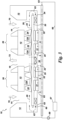
- Fig. 1 illustrates an electric pump 10 shown as a cross-section of the top half of the electric pump.
- the electric pump comprises a housing 12, defining a pair of fluid inlets 14 and a single fluid outlet 16.
- the electric pump comprises a hollow rotor 20 having an inner surface 21 and an outer surface 22. Inner surface 21 defines a rotor cavity 23.
- Stator 30 is disposed within the rotor cavity.
- the rotor is supported relative to the stator by three bearings 40 constituting a bearing span 41 (See Fig. 2 ).
- independently controllable stator sections 31 and their torque-producing complements 25, impellers 24 and diffusers 124 are shown as falling within the same portions of the bearing span defined by bearings 40.
- stator sections 31 are independently controllable, meaning that each stator section is independently powered and controlled. This feature allows for a high level of control over the performance characteristics of the pump by controlling power supply to individual stator sections 31 during operation.
- the need for less or more power to be delivered to individual stator sections may vary rapidly, as when the production fluid to be processed by the pump is a multiphase fluid comprising varying amounts of gas.
- the gas volume fraction (GVF) of a multiphase production fluid may vary significantly over a short period of time in a hydrocarbon producing well.
- stator sections are independently controlled by variable frequency drives.
- stator sections may be controlled by a combination of one or more variable frequency drives together with sensorless control techniques such as are disclosed in United States Patent Application No. 14/663691 filed March 20, 2015 .
- FIG. 1 the figure represents an electric pump 10 in operation.
- An unprocessed production fluid 70 is introduced at each of inlets 14 and into fluid flow path 29 defined by the outer surface 22 of the hollow rotor and pump stages 26, and exits the pump as processed production fluid 72 at common outlet 16.
- a portion of the production fluid is introduced into rotor cavity 23 via rotor perforations 62.
- the portion of the production fluid introduced into the rotor cavity encounters and lubricates bearings 40 before being reintroduced into fluid flow path 29.
- the direction of fluid flow through the rotor cavity is indicated by numbered elements 63.
- Pump stages 26 are arranged back to back along the outer surface of the rotor in the sense that the portions of each pump stage from which the processed production fluid 72 exits the pump stage are arranged opposite one another, or back to back, at pump outlet 16.
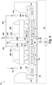
- FIG. 2 the figure illustrates an electric pump 10 provided by the present invention shown as a cross-section of the top half of the electric pump as in Fig. 1 .
- a portion of the production fluid is used as a coolant fluid for independently controllable stator sections 31.
- the pumping action of parallel, back to back pump stages 26 drives a portion of processed production fluid 72 through rotor perforations 62 and stator cooling channels 32 in directions of flow indicated by numbered elements 63.
- Bearings 40 are contacted by at least a portion of the production fluid emerging from the stator cooling channels 32 prior to returning to the main flow of the production fluid in fluid flow path 29.
- Rotor perforations 62, stator cooling channels 32, the action of pump stages 26 and the portion of the production fluid circulated through the stator sections prior to being returned to fluid flow path 29 constitute a coolant fluid recirculation system 60 in which the production fluid serves as the coolant fluid.
- a coolant fluid recirculation system 60 in which the production fluid serves as the coolant fluid.
- the figure illustrates an electric pump 10 shown as a cross-section of the top half of the electric pump as in Fig. 1 .
- the electric pump is provided with a dedicated coolant fluid circuit 66 configured to cool stator sections 31.
- Coolant fluid circuit comprises a coolant fluid cooler 67 and fluid pump 69.
- coolant fluid is introduced into stator cooling channels 32 where the coolant fluid absorbs heat from the stator section before returning to fluid cooler 67.
- numbered elements 63 indicate the direction of flow of coolant fluid.
- bearings 40 are shown as being lubricated by production fluid as in Fig. 1 . In one or more embodiments, bearings 40 are not lubricated by production fluid. In one or more embodiments, the bearings are lubricated by an exogenous fluid, such as the coolant fluid from a dedicated coolant fluid circuit. In another set of embodiments, bearings 40 are selflubricating.
- the figure represents an electric pump 10 configured as in Fig. 3 and further comprising a separator 74 configured to receive processed production fluid 72 and to separate from it a liquid-only fraction 76.
- This liquid-only fraction may be used to lubricate and/or cool bearings 40.
- the pump is configured to lubricate bearings 40E representing the two ends of the bearing span using liquid only fraction 76.
- the separator 74 may be equipped with a pump (not shown) to circulate the liquid-only fraction 76 through conduits 78 and into contact with end bearings 40E.
- the action of pump stages 26 causes the liquid-only fraction 76 to flow in the direction indicated by numbered elements 63 and subsequently enter pump flow path 29.
- the flow of the liquid-only fraction 76 to end bearings 40E may be regulated by pressure drop control valve 68.
- Perforations 62 allow a portion of the fluid being processed by the pump to enter the rotor cavity and contact all of the bearings present.
- the production fluid entering the electric pump is hot, for example a production fluid from a deep hydrocarbon producing well.
- both the cooler 67 and separator 74 may rely on the cold ambient environment to serve as a heat sink for heat contained in the production fluid and heat generated in the bearings, in the stator sections 31, and in torque-producing complements 25.
- separator 75 is located upstream of pump inlets 14 and feeds the pump with a liquid only fraction 76 derived from a multiphase production fluid, in addition to circulating a portion of liquid only fraction 76 through bearings 40E.
- FIG. 5 the figure represents an electric pump 10 in which the pump stages 26 act in series.
- unprocessed fluid 70 enters the electric pump at inlet 14A and is impelled through first pump stage 26A and emerges at outlet chamber 16A as processed fluid 72A.
- Processed fluid 72A is then driven by the action of the pump stages through conduit 78A and enters the second pump stage 26B at inlet 14B.
- Processed fluid 72A is impelled through pump stage 26B and emerges at outlet chamber 16B as further processed fluid 72B which is conducted further downstream by conduit 78B.
- outlet chambers 16A and 16B are separated by dividing wall 116 comprising seal 117 at its base.
- Seal 117 allows free rotation of the hollow rotor while inhibiting processed fluid 72A from passing from outlet chamber 16A to the adjacent outlet chamber 16B without first passing through pump stage 26B. Similarly, seal 117 inhibits further processed fluid 72B in outlet chamber 16B from entering outlet chamber 16A. In one or more embodiments, such inhibition enhances the efficiency of the electric pump.
- seal 117 is a brush seal comprising metallic seal bristles.
- seal 117 is a brush seal comprising seal bristles comprising an organic polymer. In one such embodiment, the seal bristles comprise the engineering plastic, PEEK.
- the figure represents an electric pump configured as in Fig. 5 for "in series" processing of a production fluid 70, but further comprising a dedicated coolant fluid circuit 66.
- the dedicated coolant fluid circuit 66 constitutes an additional coolant fluid recirculation system, which supplements coolant fluid recirculation system 60.
- Coolant fluid recirculation system 60 causes a portion of the production fluid being processed by the pump to contact all three bearings 40 disposed within rotor cavity 23, thereby cooling and lubricating them.
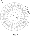
- FIG. 7 the figure represents a hollow rotor - stator subassembly 50 provided by the present invention.
- Subassembly 50 may at times herein be referred to as an electric motor, or simply a motor.
- Motor 50 is suitable for use in one or more embodiments of an electric pump 10 provided by the present invention, and as configured, constitutes a squirrel cage induction motor.
- motor 50 comprises a hollow rotor 20 defining an inner cavity 23 and a stator 30 disposed within rotor cavity 23.
- the motor is shown in cross-section and illustrates a portion of a single independently controllable stator section 31 (See Figs. 1-6 ) and a corresponding torque-producing complement 25.
- Stator slots 33 are configured to accommodate the stator windings (not shown) in a distributed winding configuration.
- Stator 30 and hollow rotor 20 are supported relative to one another by bearings 40 (not shown) which contact an inner surface 21 of the hollow rotor and a suitable outer surface 34 (See Fig. 1 ) of the stator.
- bearings 40 See Figs. 1-6
- the torque-producing rotor sections 25 may be in the form of conductive rotor bars disposed within the body of the hollow rotor 20.
- such rotor bars comprise a conductive metallic material such as aluminum or copper.
- the outer surface 22 of rotor 20 is configured to be joined to one or more impellers which may, for example be joined to the rotor outer surface in one or more shrink fitting steps in which an impeller is inserted into one or more appropriately sized and spaced grooves of a hot outer surface.
- the impellers may be welded to the outer surface of the hollow rotor.
- the stator defines a plurality of stator cooling channels 32 through which a coolant fluid may be passed in order to maintain the motor within an acceptable temperature range.
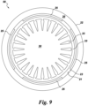
- FIG. 8 the figure represents a hollow rotor - stator subassembly 50 configured as an interior permanent magnet motor.
- the subassembly is configured essentially as in Fig. 7 with the exception that the torque-producing complements 25 to stator sections 31 are permanent magnets disposed within the body of the hollow rotor 20.
- the subassembly shown in Fig. 8 (and any of Figs. 9-12 ) should be equipped with stator cooling channels 32 (See for example Fig. 7 ) configured to be fluidly coupled to a coolant fluid recirculation system 60.
- the stator 30 comprises stator slots 33 configured to accommodate the stator windings (not shown) in a distributed winding configuration.
- the figure represents a hollow rotor - stator subassembly 50 configured as a surface permanent magnet motor.
- permanent magnets indicated as torque-producing complements 25 are attached to the inner surface 21 of the hollow rotor 20 and project into rotor cavity 23.
- the surface permanent magnets may be attached to the inner surface 21 by techniques known to those of ordinary skill in the art, such as welding and/or shrink fitting.
- the stator 30 comprises stator slots 33 configured to accommodate the stator windings (not shown) in a distributed winding configuration.
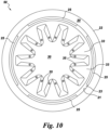
- FIG. 10 the figure represents a hollow rotor - stator subassembly 50 configured as a surface permanent magnet motor as in Fig. 9 , with the exception that the stator 30 comprises stator slots 33 configured to accommodate the stator windings 35 in a concentrated (tooth) winding configuration.
- the figure represents a hollow rotor - stator subassembly 50 configured as an inset permanent magnet motor.
- permanent magnets indicated as torque-producing complements 25 to independently controllable stator sections 31 are accommodated by grooves on the inner surface 21 of the hollow rotor 20 and do not project into rotor cavity 23.
- the permanent magnets may be attached to the hollow rotor by techniques known to those of ordinary skill in the art, such as welding and/or shrink fitting.
- the stator 30 comprises stator slots 33 configured to accommodate the stator windings (not shown) in a distributed winding configuration.
- the figure represents a hollow rotor - stator subassembly 50 configured as a synchronous reluctance motor.
- the body of the hollow rotor comprises a torque-producing complement 25, which may be, for example, a ferromagnetic material such as iron, nickel, cobalt, and aluminum-nickel-cobalt alloys such as alnico.
- the hollow rotor is comprised of a ferromagnetic material and contains a single torque-producing complement 25 along its entire length.
- Air slots 52 within the hollow rotor body provide for magnetic reluctance.
- the stator 30 comprises stator slots 33 configured to accommodate the stator windings (not shown) in a distributed winding configuration. Stator sections 31 may be controlled by microcontrollers.
Landscapes
- Engineering & Computer Science (AREA)
- Mechanical Engineering (AREA)
- General Engineering & Computer Science (AREA)
- Power Engineering (AREA)
- Mining & Mineral Resources (AREA)
- Physics & Mathematics (AREA)
- Thermal Sciences (AREA)
- Structures Of Non-Positive Displacement Pumps (AREA)
Claims (12)
- Elektrische Pumpe (10), umfassend:(a) einen hohlen Rotor (20), der eine Rotorinnenoberfläche (21), eine Rotoraußenoberfläche (22) und einen Rotorhohlraum (23) definiert;(b) einen Stator (30), umfassend eine Vielzahl von unabhängig steuerbaren Statorbereichen (31), die innerhalb des Rotorhohlraums (23) eingerichtet sind, wobei der hohle Rotor (20) (i) ein oder mehrere Laufräder (24), die an der Rotoraußenoberfläche (22) befestigt sind, und (ii) ein oder mehrere Drehmoment erzeugende Ergänzungen (25) zu den unabhängig steuerbaren Statorbereichen (31), die zusammen einen Elektromotor definieren, umfasst;(c) eine Vielzahl von Lagern (40), die konfiguriert sind, um eine Drehung des hohlen Rotors (20) zu ermöglichen, wobei die Lager (40) zwischen der Innenoberfläche des hohlen Rotors (20) und einer Außenoberfläche des Stators (30) getragen sind, wobei die elektrische Pumpe derart konfiguriert ist, dass, angetrieben durch die Wirkung des einen oder der mehreren Laufräder (24), ein Förderfluid (70) in jeden von einem oder mehreren Einlässen (14) der elektrischen Pumpe in einen Fluiddurchflusspfad (29) eingeleitet wird, der durch die Außenoberfläche (22) des Rotors definiert ist, und das Förderfluid die elektrische Pumpe an jedem von einem oder mehreren Auslässen (16) verlässt; und(d) ein Fluidrückführungssystem (60), umfassend:
Rotorperforationen (62), die sich in der Nähe des einen oder der mehreren Fluidauslässe (16) befinden, um Fluid radial in den Rotorhohlraum (23) einzuleiten, und Statorkühlkanäle (32), durch die ein Fluid geleitet werden kann, um den Motor innerhalb eines akzeptablen Temperaturbereichs zu halten, wobei die elektrische Pumpe derart konfiguriert ist, dass, angetrieben durch die Wirkung des einen oder der mehreren Laufräder (24), ein Abschnitt des Förderfluids (70) durch die Rotorperforationen (62) und durch die Statorkühlkanäle (32) fließt, und vor dem Rückführen in den Fluiddurchflusspfad (29), das Förderfluid, das aus den Statorkühlkanälen (32) austritt, auf die Vielzahl von Lagern (40) trifft und diese schmiert. - Elektrische Pumpe nach Anspruch 1, wobei der Stator (30) und der Rotor (20) als ein Käfigläufer-Induktionsmotor konfiguriert sind.
- Elektrische Pumpe nach Anspruch 1, wobei der Stator (30) und der Rotor (20) als ein Innenpermanentmagnetmotor konfiguriert sind.
- Elektrische Pumpe nach Anspruch 1, wobei der Stator (30) und der Rotor (20) als ein Synchron-Reluktanzmotor konfiguriert sind.
- Elektrische Pumpe nach Anspruch 1, wobei das eine oder die mehreren Laufräder (24) als eine einzige Pumpenstufe konfiguriert sind.
- Elektrische Pumpe nach Anspruch 1, wobei das eine oder die mehreren Laufräder (24) als eine Vielzahl von Pumpenstufen konfiguriert sind.
- Elektrische Pumpe nach Anspruch 1, wobei einer oder mehrere der Statorbereich (31) Statorwicklungen umfasst, die in einer verteilten Wicklungskonfiguration angeordnet sind.
- Elektrische Pumpe nach Anspruch 1, wobei einer oder mehrere der Statorbereiche (31) Statorwicklungen umfassen, die in einer konzentrierten Wicklungskonfiguration angeordnet sind.
- Elektrische Pumpe nach Anspruch 1, ferner umfassend:
(e) einen oder mehrere Diffusoren (124), die sich in den Fluiddurchflusspfad (29) erstrecken, der durch die Pumpe definiert ist;
wobei sich ein oder mehrere an der Außenfläche des Rotors befestigte Laufräder (24) in den Flüssigkeitsströmungspfad hinein erstrecken und es eine Vielzahl von Drehmoment erzeugenden Ergänzungen zu den unabhängig steuerbaren Statorbereichen (31) gibt. - Elektrische Pumpe nach Anspruch 9, wobei das Fluidrückführungssystem (60) konfiguriert ist, um Fluid mit einem oder mehreren der Vielzahl von Lagern (40) in Kontakt zu bringen.
- Elektrische Pumpe nach Anspruch 9, wobei der Stator (30) und der Rotor (20) als ein Käfigläufer-Induktionsmotor, ein Innenpermanentmagnetmotor, ein Oberflächenpermanentmagnetmotor oder ein Einsatzpermanentmagnetmotor; ein Synchron-Reluktanzmotor; oder eine Kombination aus zwei oder mehreren der vorstehenden Konfigurationen konfiguriert sind.
- Elektrische Pumpe nach Anspruch 9, ferner umfassend:
(f) ein Pumpengehäuse (12).
Applications Claiming Priority (3)
| Application Number | Priority Date | Filing Date | Title |
|---|---|---|---|
| US201462092307P | 2014-12-16 | 2014-12-16 | |
| US14/729,405 US10218247B2 (en) | 2014-12-16 | 2015-06-03 | Integrated motor and fluid pump |
| PCT/US2015/065668 WO2016100254A1 (en) | 2014-12-16 | 2015-12-15 | Fluid pump with external rotor motor |
Publications (3)
| Publication Number | Publication Date |
|---|---|
| EP3234367A1 EP3234367A1 (de) | 2017-10-25 |
| EP3234367B1 true EP3234367B1 (de) | 2024-10-02 |
| EP3234367B8 EP3234367B8 (de) | 2025-02-19 |
Family
ID=56110723
Family Applications (1)
| Application Number | Title | Priority Date | Filing Date |
|---|---|---|---|
| EP15820398.4A Active EP3234367B8 (de) | 2014-12-16 | 2015-12-15 | Flüssigkeitpumpe mit aussenläufermotor |
Country Status (4)
| Country | Link |
|---|---|
| US (1) | US10218247B2 (de) |
| EP (1) | EP3234367B8 (de) |
| ES (1) | ES2995265T3 (de) |
| WO (1) | WO2016100254A1 (de) |
Families Citing this family (20)
| Publication number | Priority date | Publication date | Assignee | Title |
|---|---|---|---|---|
| NO347975B1 (en) * | 2016-09-20 | 2024-06-03 | Vetco Gray Scandinavia As | Improved arrangement for pressurizing of fluid |
| WO2018156131A1 (en) | 2017-02-23 | 2018-08-30 | Halliburton Energy Services, Inc. | Modular pumping system |
| WO2019084424A1 (en) * | 2017-10-27 | 2019-05-02 | Fmc Technologies, Inc. | MANAGEMENT OF MULTIPLE FLUIDS WITH CENTRIFUGAL FLOW FILTER SYSTEMS |
| US11162497B2 (en) | 2017-11-13 | 2021-11-02 | Onesubsea Ip Uk Limited | System for moving fluid with opposed axial forces |
| US20200056462A1 (en) * | 2018-08-16 | 2020-02-20 | Saudi Arabian Oil Company | Motorized pump |
| US20200056615A1 (en) | 2018-08-16 | 2020-02-20 | Saudi Arabian Oil Company | Motorized pump |
| RU2732655C1 (ru) * | 2019-07-23 | 2020-09-21 | Общество С Ограниченной Ответственностью "Нефтекамский Машиностроительный Завод" | Центробежный секционный насос с двумя параллельными потоками перекачиваемой среды |
| US11371326B2 (en) * | 2020-06-01 | 2022-06-28 | Saudi Arabian Oil Company | Downhole pump with switched reluctance motor |
| US11499563B2 (en) | 2020-08-24 | 2022-11-15 | Saudi Arabian Oil Company | Self-balancing thrust disk |
| US11532959B2 (en) * | 2020-09-07 | 2022-12-20 | ElectromagnetiX LLC | Electric submersible pump motor stabilized by electromagnetics |
| US11920469B2 (en) | 2020-09-08 | 2024-03-05 | Saudi Arabian Oil Company | Determining fluid parameters |
| DE102020215183A1 (de) * | 2020-12-02 | 2022-06-02 | BSH Hausgeräte GmbH | Rotor mit integriertem Lüfter, Elektromotor, Pumpenvorrichtung, Haushaltsgerät und Herstellungsverfahren |
| US11644351B2 (en) | 2021-03-19 | 2023-05-09 | Saudi Arabian Oil Company | Multiphase flow and salinity meter with dual opposite handed helical resonators |
| US11591899B2 (en) | 2021-04-05 | 2023-02-28 | Saudi Arabian Oil Company | Wellbore density meter using a rotor and diffuser |
| US11913464B2 (en) | 2021-04-15 | 2024-02-27 | Saudi Arabian Oil Company | Lubricating an electric submersible pump |
| US11994016B2 (en) | 2021-12-09 | 2024-05-28 | Saudi Arabian Oil Company | Downhole phase separation in deviated wells |
| US12258954B2 (en) | 2021-12-15 | 2025-03-25 | Saudi Arabian Oil Company | Continuous magnetic positive displacement pump |
| US12085687B2 (en) | 2022-01-10 | 2024-09-10 | Saudi Arabian Oil Company | Model-constrained multi-phase virtual flow metering and forecasting with machine learning |
| CN116085275A (zh) * | 2023-03-07 | 2023-05-09 | 铱塔(深圳)科技有限公司 | 一种堆叠泵组 |
| CN117345655B (zh) * | 2023-12-05 | 2024-02-27 | 四川川工泵业有限公司 | 一种泵撬 |
Family Cites Families (17)
| Publication number | Priority date | Publication date | Assignee | Title |
|---|---|---|---|---|
| US1661360A (en) * | 1927-06-04 | 1928-03-06 | Rheuben M Clark | Pump |
| US2942555A (en) | 1957-04-15 | 1960-06-28 | Rinaldo F Pezzillo | Combination pump and motor |
| US3007065A (en) * | 1959-03-23 | 1961-10-31 | Task Corp | Fluid cooled motor |
| US3132595A (en) | 1961-10-30 | 1964-05-12 | Layne & Bowler Pump Company | Axial flow pump |
| US3433163A (en) * | 1966-11-07 | 1969-03-18 | Gen Dynamics Corp | Pump |
| CN1005348B (zh) | 1987-03-23 | 1989-10-04 | 核工业部第二研究设计院 | 屏蔽泵 |
| DE59603933D1 (de) | 1995-08-24 | 2000-01-20 | Sulzer Electronics Ag Winterth | Elektromotor |
| US5795135A (en) | 1995-12-05 | 1998-08-18 | Westinghouse Electric Corp. | Sub-sea pumping system and an associated method including pressure compensating arrangement for cooling and lubricating fluid |
| TW396673B (en) * | 1995-12-22 | 2000-07-01 | Satake Eng Co Ltd | Induction motor driving device and the method for its starting operation |
| JPH09264292A (ja) | 1996-03-29 | 1997-10-07 | Ebara Corp | 高温用モータポンプ |
| US6457950B1 (en) | 2000-05-04 | 2002-10-01 | Flowserve Management Company | Sealless multiphase screw-pump-and-motor package |
| JP4722309B2 (ja) | 2000-12-27 | 2011-07-13 | 三菱電機株式会社 | 回転電機及びこの回転電機を用いた滑車駆動装置 |
| US20090098003A1 (en) | 2007-10-11 | 2009-04-16 | General Electric Company | Multiphase screw pump |
| US8696331B2 (en) | 2008-05-06 | 2014-04-15 | Fmc Technologies, Inc. | Pump with magnetic bearings |
| US8905729B2 (en) | 2011-12-30 | 2014-12-09 | Peopleflo Manufacturing, Inc. | Rotodynamic pump with electro-magnet coupling inside the impeller |
| US9863476B2 (en) | 2013-03-15 | 2018-01-09 | Toshiba International Corporation | Self-cooled and-or self lubricated electric motor bearing systems |
| US9595903B2 (en) | 2015-03-20 | 2017-03-14 | General Electric Company | Controller for motor |
-
2015
- 2015-06-03 US US14/729,405 patent/US10218247B2/en active Active
- 2015-12-15 EP EP15820398.4A patent/EP3234367B8/de active Active
- 2015-12-15 ES ES15820398T patent/ES2995265T3/es active Active
- 2015-12-15 WO PCT/US2015/065668 patent/WO2016100254A1/en not_active Ceased
Also Published As
| Publication number | Publication date |
|---|---|
| US10218247B2 (en) | 2019-02-26 |
| EP3234367A1 (de) | 2017-10-25 |
| WO2016100254A1 (en) | 2016-06-23 |
| EP3234367B8 (de) | 2025-02-19 |
| ES2995265T3 (en) | 2025-02-10 |
| US20160169231A1 (en) | 2016-06-16 |
Similar Documents
| Publication | Publication Date | Title |
|---|---|---|
| EP3234367B1 (de) | Flüssigkeitpumpe mit aussenläufermotor | |
| CN109997296B (zh) | 用于冷却电机的方法以及使用这种方法的电机 | |
| EP2715056B1 (de) | In flüssigkeit getauchter und durch einen permanentmagnetmotor direkt angetriebener unterseeverdichter mit einem stator und einem rotor | |
| CN103026597B (zh) | 流体冷却的电机 | |
| JP5911033B1 (ja) | 回転電機の運転方法 | |
| US9680351B2 (en) | Electrical machine having cooling features | |
| KR20180027556A (ko) | 회전 전기 기기 냉각 구조 | |
| EP2897259A2 (de) | Rotierende elektrische Maschine | |
| EP1593192A1 (de) | Drehmaschinen-kühlsystem | |
| CN108092432A (zh) | 电机 | |
| US20170261004A1 (en) | Centrifugal pressure booster and method for modifying or constructing a centrifugal pressure booster | |
| EP2642635A2 (de) | Flüssigkeitsgekühlte dynamoelektrische Maschine | |
| JP7116739B2 (ja) | チラーセンブリのための誘導電動機及び電動機のための冷却システム | |
| EP3244513B1 (de) | Elektromotor | |
| US20070075595A1 (en) | Motor frame having embedded cooling coil | |
| US20150326074A1 (en) | Electric machine and systems comprising the same | |
| KR20150011970A (ko) | 구동모터의 냉각 구조 | |
| JP2020018116A (ja) | ロータ及び回転電気 | |
| GB2499114A (en) | Hollow rotor for a motor and an electrical generator | |
| KR101702023B1 (ko) | 전동기 냉각 시스템 |
Legal Events
| Date | Code | Title | Description |
|---|---|---|---|
| STAA | Information on the status of an ep patent application or granted ep patent |
Free format text: STATUS: THE INTERNATIONAL PUBLICATION HAS BEEN MADE |
|
| PUAI | Public reference made under article 153(3) epc to a published international application that has entered the european phase |
Free format text: ORIGINAL CODE: 0009012 |
|
| STAA | Information on the status of an ep patent application or granted ep patent |
Free format text: STATUS: REQUEST FOR EXAMINATION WAS MADE |
|
| 17P | Request for examination filed |
Effective date: 20170717 |
|
| AK | Designated contracting states |
Kind code of ref document: A1 Designated state(s): AL AT BE BG CH CY CZ DE DK EE ES FI FR GB GR HR HU IE IS IT LI LT LU LV MC MK MT NL NO PL PT RO RS SE SI SK SM TR |
|
| AX | Request for extension of the european patent |
Extension state: BA ME |
|
| DAV | Request for validation of the european patent (deleted) | ||
| DAX | Request for extension of the european patent (deleted) | ||
| STAA | Information on the status of an ep patent application or granted ep patent |
Free format text: STATUS: EXAMINATION IS IN PROGRESS |
|
| 17Q | First examination report despatched |
Effective date: 20190301 |
|
| P01 | Opt-out of the competence of the unified patent court (upc) registered |
Effective date: 20230526 |
|
| RIC1 | Information provided on ipc code assigned before grant |
Ipc: H02K 21/22 20060101ALN20240502BHEP Ipc: H02K 19/10 20060101ALN20240502BHEP Ipc: H02K 17/16 20060101ALN20240502BHEP Ipc: H02K 16/00 20060101ALI20240502BHEP Ipc: H02K 9/197 20060101ALI20240502BHEP Ipc: H02K 7/14 20060101ALI20240502BHEP Ipc: H02K 1/279 20220101ALI20240502BHEP Ipc: H02K 1/2788 20220101ALI20240502BHEP Ipc: F04D 31/00 20060101ALI20240502BHEP Ipc: F04D 29/58 20060101ALI20240502BHEP Ipc: F04D 29/06 20060101ALI20240502BHEP Ipc: F04D 13/10 20060101ALI20240502BHEP Ipc: F04D 13/06 20060101ALI20240502BHEP Ipc: F04D 1/06 20060101AFI20240502BHEP |
|
| GRAP | Despatch of communication of intention to grant a patent |
Free format text: ORIGINAL CODE: EPIDOSNIGR1 |
|
| STAA | Information on the status of an ep patent application or granted ep patent |
Free format text: STATUS: GRANT OF PATENT IS INTENDED |
|
| RIC1 | Information provided on ipc code assigned before grant |
Ipc: H02K 21/22 20060101ALN20240514BHEP Ipc: H02K 19/10 20060101ALN20240514BHEP Ipc: H02K 17/16 20060101ALN20240514BHEP Ipc: H02K 16/00 20060101ALI20240514BHEP Ipc: H02K 9/197 20060101ALI20240514BHEP Ipc: H02K 7/14 20060101ALI20240514BHEP Ipc: H02K 1/279 20220101ALI20240514BHEP Ipc: H02K 1/2788 20220101ALI20240514BHEP Ipc: F04D 31/00 20060101ALI20240514BHEP Ipc: F04D 29/58 20060101ALI20240514BHEP Ipc: F04D 29/06 20060101ALI20240514BHEP Ipc: F04D 13/10 20060101ALI20240514BHEP Ipc: F04D 13/06 20060101ALI20240514BHEP Ipc: F04D 1/06 20060101AFI20240514BHEP |
|
| RIC1 | Information provided on ipc code assigned before grant |
Ipc: H02K 21/22 20060101ALN20240527BHEP Ipc: H02K 19/10 20060101ALN20240527BHEP Ipc: H02K 17/16 20060101ALN20240527BHEP Ipc: H02K 16/00 20060101ALI20240527BHEP Ipc: H02K 9/197 20060101ALI20240527BHEP Ipc: H02K 7/14 20060101ALI20240527BHEP Ipc: H02K 1/279 20220101ALI20240527BHEP Ipc: H02K 1/2788 20220101ALI20240527BHEP Ipc: F04D 31/00 20060101ALI20240527BHEP Ipc: F04D 29/58 20060101ALI20240527BHEP Ipc: F04D 29/06 20060101ALI20240527BHEP Ipc: F04D 13/10 20060101ALI20240527BHEP Ipc: F04D 13/06 20060101ALI20240527BHEP Ipc: F04D 1/06 20060101AFI20240527BHEP |
|
| INTG | Intention to grant announced |
Effective date: 20240611 |
|
| GRAS | Grant fee paid |
Free format text: ORIGINAL CODE: EPIDOSNIGR3 |
|
| GRAA | (expected) grant |
Free format text: ORIGINAL CODE: 0009210 |
|
| STAA | Information on the status of an ep patent application or granted ep patent |
Free format text: STATUS: THE PATENT HAS BEEN GRANTED |
|
| RAP1 | Party data changed (applicant data changed or rights of an application transferred) |
Owner name: NUOVO PIGNONE TECHNOLOGIE - S.R.L. |
|
| AK | Designated contracting states |
Kind code of ref document: B1 Designated state(s): AL AT BE BG CH CY CZ DE DK EE ES FI FR GB GR HR HU IE IS IT LI LT LU LV MC MK MT NL NO PL PT RO RS SE SI SK SM TR |
|
| REG | Reference to a national code |
Ref country code: GB Ref legal event code: FG4D |
|
| REG | Reference to a national code |
Ref country code: CH Ref legal event code: EP |
|
| REG | Reference to a national code |
Ref country code: IE Ref legal event code: FG4D |
|
| REG | Reference to a national code |
Ref country code: DE Ref legal event code: R096 Ref document number: 602015090044 Country of ref document: DE |
|
| REG | Reference to a national code |
Ref country code: NL Ref legal event code: FP |
|
| PGFP | Annual fee paid to national office [announced via postgrant information from national office to epo] |
Ref country code: NL Payment date: 20241121 Year of fee payment: 10 |
|
| PGFP | Annual fee paid to national office [announced via postgrant information from national office to epo] |
Ref country code: DE Payment date: 20241121 Year of fee payment: 10 |
|
| PGFP | Annual fee paid to national office [announced via postgrant information from national office to epo] |
Ref country code: GB Payment date: 20241122 Year of fee payment: 10 |
|
| PGFP | Annual fee paid to national office [announced via postgrant information from national office to epo] |
Ref country code: FR Payment date: 20241121 Year of fee payment: 10 |
|
| PGFP | Annual fee paid to national office [announced via postgrant information from national office to epo] |
Ref country code: AT Payment date: 20241122 Year of fee payment: 10 |
|
| PGFP | Annual fee paid to national office [announced via postgrant information from national office to epo] |
Ref country code: CZ Payment date: 20241127 Year of fee payment: 10 |
|
| REG | Reference to a national code |
Ref country code: DE Ref legal event code: R081 Ref document number: 602015090044 Country of ref document: DE Owner name: NUOVO PIGNONE TECNOLOGIE - S.R.L., IT Free format text: FORMER OWNER: NUOVO PIGNONE TECHNOLOGIE S.R.L., FLORENCE, IT Ref country code: LT Ref legal event code: MG9D |
|
| REG | Reference to a national code |
Ref country code: CH Ref legal event code: PK Free format text: BERICHTIGUNG B8 Ref country code: CH Ref legal event code: PK Free format text: BERICHTIGUNGEN |
|
| REG | Reference to a national code |
Ref country code: ES Ref legal event code: FG2A Ref document number: 2995265 Country of ref document: ES Kind code of ref document: T3 Effective date: 20250210 |
|
| RAP2 | Party data changed (patent owner data changed or rights of a patent transferred) |
Owner name: NUOVO PIGNONE TECNOLOGIE - S.R.L. |
|
| PG25 | Lapsed in a contracting state [announced via postgrant information from national office to epo] |
Ref country code: PT Free format text: LAPSE BECAUSE OF FAILURE TO SUBMIT A TRANSLATION OF THE DESCRIPTION OR TO PAY THE FEE WITHIN THE PRESCRIBED TIME-LIMIT Effective date: 20250203 Ref country code: HR Free format text: LAPSE BECAUSE OF FAILURE TO SUBMIT A TRANSLATION OF THE DESCRIPTION OR TO PAY THE FEE WITHIN THE PRESCRIBED TIME-LIMIT Effective date: 20241002 Ref country code: IS Free format text: LAPSE BECAUSE OF FAILURE TO SUBMIT A TRANSLATION OF THE DESCRIPTION OR TO PAY THE FEE WITHIN THE PRESCRIBED TIME-LIMIT Effective date: 20250202 |
|
| PG25 | Lapsed in a contracting state [announced via postgrant information from national office to epo] |
Ref country code: FI Free format text: LAPSE BECAUSE OF FAILURE TO SUBMIT A TRANSLATION OF THE DESCRIPTION OR TO PAY THE FEE WITHIN THE PRESCRIBED TIME-LIMIT Effective date: 20241002 |
|
| PG25 | Lapsed in a contracting state [announced via postgrant information from national office to epo] |
Ref country code: BG Free format text: LAPSE BECAUSE OF FAILURE TO SUBMIT A TRANSLATION OF THE DESCRIPTION OR TO PAY THE FEE WITHIN THE PRESCRIBED TIME-LIMIT Effective date: 20241002 |
|
| PGFP | Annual fee paid to national office [announced via postgrant information from national office to epo] |
Ref country code: ES Payment date: 20250102 Year of fee payment: 10 |
|
| PG25 | Lapsed in a contracting state [announced via postgrant information from national office to epo] |
Ref country code: NO Free format text: LAPSE BECAUSE OF FAILURE TO SUBMIT A TRANSLATION OF THE DESCRIPTION OR TO PAY THE FEE WITHIN THE PRESCRIBED TIME-LIMIT Effective date: 20250102 |
|
| PG25 | Lapsed in a contracting state [announced via postgrant information from national office to epo] |
Ref country code: LV Free format text: LAPSE BECAUSE OF FAILURE TO SUBMIT A TRANSLATION OF THE DESCRIPTION OR TO PAY THE FEE WITHIN THE PRESCRIBED TIME-LIMIT Effective date: 20241002 Ref country code: GR Free format text: LAPSE BECAUSE OF FAILURE TO SUBMIT A TRANSLATION OF THE DESCRIPTION OR TO PAY THE FEE WITHIN THE PRESCRIBED TIME-LIMIT Effective date: 20250103 |
|
| PGFP | Annual fee paid to national office [announced via postgrant information from national office to epo] |
Ref country code: CH Payment date: 20250101 Year of fee payment: 10 |
|
| PG25 | Lapsed in a contracting state [announced via postgrant information from national office to epo] |
Ref country code: PL Free format text: LAPSE BECAUSE OF FAILURE TO SUBMIT A TRANSLATION OF THE DESCRIPTION OR TO PAY THE FEE WITHIN THE PRESCRIBED TIME-LIMIT Effective date: 20241002 |
|
| PG25 | Lapsed in a contracting state [announced via postgrant information from national office to epo] |
Ref country code: RS Free format text: LAPSE BECAUSE OF FAILURE TO SUBMIT A TRANSLATION OF THE DESCRIPTION OR TO PAY THE FEE WITHIN THE PRESCRIBED TIME-LIMIT Effective date: 20250102 |
|
| PG25 | Lapsed in a contracting state [announced via postgrant information from national office to epo] |
Ref country code: SM Free format text: LAPSE BECAUSE OF FAILURE TO SUBMIT A TRANSLATION OF THE DESCRIPTION OR TO PAY THE FEE WITHIN THE PRESCRIBED TIME-LIMIT Effective date: 20241002 |
|
| REG | Reference to a national code |
Ref country code: DE Ref legal event code: R097 Ref document number: 602015090044 Country of ref document: DE |
|
| PG25 | Lapsed in a contracting state [announced via postgrant information from national office to epo] |
Ref country code: MC Free format text: LAPSE BECAUSE OF FAILURE TO SUBMIT A TRANSLATION OF THE DESCRIPTION OR TO PAY THE FEE WITHIN THE PRESCRIBED TIME-LIMIT Effective date: 20241002 |
|
| PG25 | Lapsed in a contracting state [announced via postgrant information from national office to epo] |
Ref country code: DK Free format text: LAPSE BECAUSE OF FAILURE TO SUBMIT A TRANSLATION OF THE DESCRIPTION OR TO PAY THE FEE WITHIN THE PRESCRIBED TIME-LIMIT Effective date: 20241002 |
|
| PG25 | Lapsed in a contracting state [announced via postgrant information from national office to epo] |
Ref country code: RO Free format text: LAPSE BECAUSE OF FAILURE TO SUBMIT A TRANSLATION OF THE DESCRIPTION OR TO PAY THE FEE WITHIN THE PRESCRIBED TIME-LIMIT Effective date: 20241002 |
|
| PG25 | Lapsed in a contracting state [announced via postgrant information from national office to epo] |
Ref country code: SK Free format text: LAPSE BECAUSE OF FAILURE TO SUBMIT A TRANSLATION OF THE DESCRIPTION OR TO PAY THE FEE WITHIN THE PRESCRIBED TIME-LIMIT Effective date: 20241002 |
|
| PG25 | Lapsed in a contracting state [announced via postgrant information from national office to epo] |
Ref country code: IT Free format text: LAPSE BECAUSE OF FAILURE TO SUBMIT A TRANSLATION OF THE DESCRIPTION OR TO PAY THE FEE WITHIN THE PRESCRIBED TIME-LIMIT Effective date: 20241002 |
|
| PLBE | No opposition filed within time limit |
Free format text: ORIGINAL CODE: 0009261 |
|
| STAA | Information on the status of an ep patent application or granted ep patent |
Free format text: STATUS: NO OPPOSITION FILED WITHIN TIME LIMIT |
|
| PG25 | Lapsed in a contracting state [announced via postgrant information from national office to epo] |
Ref country code: LU Free format text: LAPSE BECAUSE OF NON-PAYMENT OF DUE FEES Effective date: 20241215 |
|
| PG25 | Lapsed in a contracting state [announced via postgrant information from national office to epo] |
Ref country code: SE Free format text: LAPSE BECAUSE OF FAILURE TO SUBMIT A TRANSLATION OF THE DESCRIPTION OR TO PAY THE FEE WITHIN THE PRESCRIBED TIME-LIMIT Effective date: 20241002 |
|
| 26N | No opposition filed |
Effective date: 20250703 |
|
| REG | Reference to a national code |
Ref country code: BE Ref legal event code: MM Effective date: 20241231 |
|
| PG25 | Lapsed in a contracting state [announced via postgrant information from national office to epo] |
Ref country code: BE Free format text: LAPSE BECAUSE OF NON-PAYMENT OF DUE FEES Effective date: 20241231 |
|
| PG25 | Lapsed in a contracting state [announced via postgrant information from national office to epo] |
Ref country code: IE Free format text: LAPSE BECAUSE OF NON-PAYMENT OF DUE FEES Effective date: 20241215 |