EP3233587B1 - Antitheft device for steering column - Google Patents
Antitheft device for steering column Download PDFInfo
- Publication number
- EP3233587B1 EP3233587B1 EP15801863.0A EP15801863A EP3233587B1 EP 3233587 B1 EP3233587 B1 EP 3233587B1 EP 15801863 A EP15801863 A EP 15801863A EP 3233587 B1 EP3233587 B1 EP 3233587B1
- Authority
- EP
- European Patent Office
- Prior art keywords
- bolt
- holding
- rotor
- housing
- key insert
- Prior art date
- Legal status (The legal status is an assumption and is not a legal conclusion. Google has not performed a legal analysis and makes no representation as to the accuracy of the status listed.)
- Active
Links
- 230000000903 blocking effect Effects 0.000 claims description 6
- 238000001514 detection method Methods 0.000 claims description 4
- 230000006835 compression Effects 0.000 description 6
- 238000007906 compression Methods 0.000 description 6
- 238000012550 audit Methods 0.000 description 1
- 238000003780 insertion Methods 0.000 description 1
- 230000037431 insertion Effects 0.000 description 1
- 238000012423 maintenance Methods 0.000 description 1
- 238000004519 manufacturing process Methods 0.000 description 1
- 230000000717 retained effect Effects 0.000 description 1
- 230000001131 transforming effect Effects 0.000 description 1
Images


Classifications
-
- B—PERFORMING OPERATIONS; TRANSPORTING
- B60—VEHICLES IN GENERAL
- B60R—VEHICLES, VEHICLE FITTINGS, OR VEHICLE PARTS, NOT OTHERWISE PROVIDED FOR
- B60R25/00—Fittings or systems for preventing or indicating unauthorised use or theft of vehicles
- B60R25/01—Fittings or systems for preventing or indicating unauthorised use or theft of vehicles operating on vehicle systems or fittings, e.g. on doors, seats or windscreens
- B60R25/02—Fittings or systems for preventing or indicating unauthorised use or theft of vehicles operating on vehicle systems or fittings, e.g. on doors, seats or windscreens operating on the steering mechanism
- B60R25/021—Fittings or systems for preventing or indicating unauthorised use or theft of vehicles operating on vehicle systems or fittings, e.g. on doors, seats or windscreens operating on the steering mechanism restraining movement of the steering column or steering wheel hub, e.g. restraining means controlled by ignition switch
- B60R25/0211—Fittings or systems for preventing or indicating unauthorised use or theft of vehicles operating on vehicle systems or fittings, e.g. on doors, seats or windscreens operating on the steering mechanism restraining movement of the steering column or steering wheel hub, e.g. restraining means controlled by ignition switch comprising a locking member radially and linearly moved towards the steering column
- B60R25/02115—Fittings or systems for preventing or indicating unauthorised use or theft of vehicles operating on vehicle systems or fittings, e.g. on doors, seats or windscreens operating on the steering mechanism restraining movement of the steering column or steering wheel hub, e.g. restraining means controlled by ignition switch comprising a locking member radially and linearly moved towards the steering column key actuated
- B60R25/02118—Fittings or systems for preventing or indicating unauthorised use or theft of vehicles operating on vehicle systems or fittings, e.g. on doors, seats or windscreens operating on the steering mechanism restraining movement of the steering column or steering wheel hub, e.g. restraining means controlled by ignition switch comprising a locking member radially and linearly moved towards the steering column key actuated with linear bolt motion parallel to the lock axis
- B60R25/02121—Fittings or systems for preventing or indicating unauthorised use or theft of vehicles operating on vehicle systems or fittings, e.g. on doors, seats or windscreens operating on the steering mechanism restraining movement of the steering column or steering wheel hub, e.g. restraining means controlled by ignition switch comprising a locking member radially and linearly moved towards the steering column key actuated with linear bolt motion parallel to the lock axis comprising safety devices avoiding locking until removal of the key
Definitions
- the present application relates to an antitheft device for steering column, in particular of a motor vehicle.
- a motor vehicle comprises a starting control device in the form of a lock comprising a rotor and a stator. Said lock allows the motor vehicle to be started by rotating the rotor by a drive means, for example a key insert.
- the rotor is movable in the stator in several angular positions for which the steering column is blocked or unlocked by a bolt.
- the lock is connected to a rotary cam member disposed between the stator and the rotor so that the cam can be rotated with the rotor.
- the cam then controls the movement of the bolt.
- the latter can take two positions: a locking position in which the bolt is received in a housing of the steering column blocking any movement of the latter and an unlocking position in which the bolt is at a distance from the steering column allowing all movement of the latter.
- the regulation requires that the bolt is retained in the unlocked position until the key is completely or partially removed from the antitheft device voluntarily.
- the document WO3023 / 049258A1 discloses an antitheft device for steering column including a motor vehicle, comprising a latch comprising a rotor movable in rotation about an axis of rotation extending along its longitudinal axis and housed in a stator fixed relative to the rotor, said rotor comprising a housing adapted to receive a key insert, a cam configured to be controlled by said rotor, a bolt driven by said cam to assume a locking position of the steering column and an unlocking position thereof, and a device for holding the bolt being configured to detect the presence of the key insert in the housing by a movement between a holding position of the bolt in the unlocking position when the key insert is in the housing and a waiting position in which the holding device is remote from the bolt when the key insert is not in the housing.
- antitheft devices are particularly suitable when the axes of rotation of the rotor and the camshaft are coincident and when the bolt has a parallel or perpendicular translation axis the camshaft.
- automobile manufacturers may be required to develop or require, according to their needs and production constraints, antitheft devices having a general shape in "Y", that is to say where the rotor and the camshaft have axes of rotation intersecting and where the axis of translation of the bolt passes through this crossing, each of these elements forming a branch of the "Y”. It is therefore important to adapt the means for transmitting and transforming the rotational movements of the rotor, and by extension of the camshaft, in translational movement of the bolt to this conformation "Y" of the antitheft device.
- the bolt is held in unlocking position with a single piece the holding device which cooperates directly with the lock rotor.
- said device is capable of being activated and deactivated depending on the presence or absence of the key insert in the rotor.
- Maintaining the bolt unlocking position is therefore more robust and simpler to implement, because of the decrease in the number of elements in the kinematic, while remaining very effective.
- the present invention also relates to a motor vehicle, comprising an antitheft device of the invention.
- the rotor 3 is thus substantially elongate in shape along the longitudinal axis 4.
- the rotor 3 may be substantially cylindrical in shape.
- the rotor 3 has an opening 3a opening into a housing (not shown) adapted to receive the drive means (not shown), such as a key insert actuated by a user.
- the key insert may typically comprise one or more tracks adapted to move flakes (not shown) arranged longitudinally in openings 3b provided for this purpose in the rotor 3 along the longitudinal axis 4 of the latter.
- the flakes make it possible to prevent the insertion of a key insert that does not correspond to the combination of the flakes of the rotor 3 and also to prevent the rotor 3 from rotating.
- the stator 5 comprises a substantially elongated housing adapted to receive said rotor 3.
- the stator 5 is typically immobile with respect to the rotor 3.
- the cam 7 rotatable along the longitudinal axis 8 is adapted to be rotated by the rotor 3.
- a gear means 10 such as a pinion
- the pinion 10 typically has a toothing 10a adapted to cooperate with a toothing 11 on the end 12 of the cam.
- the rotary member 7 may be a cam of any shape, in particular substantially cylindrical.
- the bolt 8 is driven by said cam 7 to take a locking position of the steering column and a release position thereof.
- the bolt extends along a longitudinal axis 9 and is received in the housing 14 of a housing 13 for protecting the movement of the bolt.
- the bolt 8 has a translational movement along the longitudinal axis 9 in order to come block and unblock the steering column.
- the steering column may thus comprise one or more housings adapted to receive the end of the bolt 8.
- the bolt 8 is associated with a springback means 108, in particular a spring in compression (see figure 8 ) or a torsion spring such as a spiral spring (see Figures 1 to 7 ).
- the elastic return means comprises an end 108a fixed to a stator and an end 108b fixed against the bolt 8.
- the free end 108a is configured to come into compression under a stud 107 of the separate bolt of the stud 15 engaging on the cam profile 16
- the free end 108a is configured to come directly against the face of the bolt 8.
- the cam 7 drives the bolt 8 via a stud 15 disposed on the surface of the bolt 8 opposite the cam 7 which is capable of following the profile of the cam 7.
- the cam 7 has a non-circular cam profile 16 to allow the translation of the bolt 8 between the locking position and the unlocking position of the steering column.
- the device 1 of the invention also comprises a holding device 100 of the bolt configured to detect the presence of the key insert in the housing by a movement between a holding position of the bolt 8 in the unlocking position when the insert key is in the housing and a waiting position in which the holding device is remote from the bolt 8 when the key insert is not in the housing.
- the holding device 100 has a holding end 101 configured to lock the bolt 8 in the unlocking position and a contact end 102 configured to detect the presence of the key insert.
- the holding device 100 is rotatable along an axis 109 substantially perpendicular to the longitudinal axis 4 of the lock.
- the holding device detecting a key insert either directly by the contact end or indirectly, starts to pivot about the axis of rotation of said holding means 100.
- the latch 2 comprises an intermediate device 121 for detecting the presence of a key insert in the housing and cooperating with the contact end 102 in order to drive the holding device 100 into the holding position and the position wait.
- the holding device 100 is associated with a spring return means 104, in particular a spring in compression.
- the elastic return means comprises an end 104a fixed to a fixed part of the antitheft device of the invention and an end 104b fixed to the holding device 100.
- the bolt 8 and the holding end 101 of the locking device are in contact during the passage of the bolt 8 from the locking position to the unlocking position.
- the end of the bolt 105 facing the holding end 101 has a ramp 110 on which bears the holding end when the bolt moves from the locking position to the unlocking position.
- the end of the bolt 105 facing the holding end 101 has a cavity 106 adapted to receive the holding end 101.
- the contact end 101 has a hook shape intended to come into a cavity 120 of the latch in the waiting position, said cavity 120 being opposite the housing of the key insert.
- the contact end 102 is configured to come to standby position in the cavity 120 of the lock 2.
- At least a portion of the intermediate sensing device 121 is received in the cavity 120.
- the key insert is not inserted into the rotor housing.
- the bolt 8 is in the locking position of the steering column and the holding device 100 is disposed at a distance from said bolt 8.
- the key insert is introduced into the housing of the latch 2.
- the holding device 100 detects the presence of the key either directly through the contact end 102 passing through the cavity of the latch 2 or via an intermediate device 121.
- the detection of the intermediate device 121 results in the output from the cavity 120 of a portion of said intermediate device 121.
- the holding device 100 being supported on the latter, the holding device 100 pivots and brings together the holding end 101 of the bolt 8 which comes into contact on the profile of the bolt, in particular on the ramp 110.
- the rotor 3 rotates about the longitudinal axis 4 and drives the cam 7 rotates via the pinion 10.
- the stud 15 then follows the cam profile 16 and the bolt 8 rises from the unlocking position to the locking position along its longitudinal axis 9.
- the holding device 100 follows the profile of the bolt to be near the cavity 106.
- the bolt 8 is at the top of its stroke in its unlocking position and the holding device 100 is housed in the cavity 106.
- the bolt 8 is locked in this position.
- the key insert is removed from the housing, the contact end 102 then translates into the cavity of the rotor 3 which rotates about its axis of rotation the holding device 100.
- the holding end 101 is thus released from the cavity 106.
- the bolt 8 is released to return to the blocking position.
Landscapes
- Engineering & Computer Science (AREA)
- Mechanical Engineering (AREA)
- Lock And Its Accessories (AREA)
Description
La présente demande concerne un dispositif antivol pour colonne de direction, notamment d'un véhicule automobile.The present application relates to an antitheft device for steering column, in particular of a motor vehicle.
Usuellement, un véhicule automobile comporte un dispositif de commande de démarrage sous la forme d'un verrou comportant un rotor et un stator. Ledit verrou permet le démarrage du véhicule automobile par la mise en rotation du rotor par un moyen d'entraînement, par exemple un insert de clé.Usually, a motor vehicle comprises a starting control device in the form of a lock comprising a rotor and a stator. Said lock allows the motor vehicle to be started by rotating the rotor by a drive means, for example a key insert.
Le rotor est mobile dans le stator dans plusieurs positions angulaires pour lesquelles la colonne de direction est bloquée ou débloquée par un pêne.The rotor is movable in the stator in several angular positions for which the steering column is blocked or unlocked by a bolt.
Pour ce faire, le verrou est relié à un organe rotatif formant came disposé entre le stator et le rotor de sorte que la came puisse être entraînée en rotation avec le rotor. La came commande alors le mouvement du pêne. Ce dernier peut prendre deux positions : une positions de blocage dans laquelle le pêne est reçu dans un logement de la colonne de direction bloquant tout mouvement de cette dernière et une position de déblocage dans laquelle le pêne est à distance de la colonne de direction autorisant tout mouvement de cette dernière.To do this, the lock is connected to a rotary cam member disposed between the stator and the rotor so that the cam can be rotated with the rotor. The cam then controls the movement of the bolt. The latter can take two positions: a locking position in which the bolt is received in a housing of the steering column blocking any movement of the latter and an unlocking position in which the bolt is at a distance from the steering column allowing all movement of the latter.
Lorsqu'un utilisateur a réalisé une première rotation de la clef pour déverrouiller la colonne de direction, la réglementation demande que le pêne soit retenu en position de déblocage tant que la clef n'est pas totalement ou partiellement retirée du dispositif antivol de manière volontaire.When a user has made a first rotation of the key to unlock the steering column, the regulation requires that the bolt is retained in the unlocked position until the key is completely or partially removed from the antitheft device voluntarily.
Il est connu d'utiliser un système d'accroche par levier dans lequel le maintien du pêne dans la position de déblocage de la colonne de direction, comme exigée par la réglementation, est assuré à l'aide d'une tirette commandé par un levier. Le levier coopère avec le rotor permettant la translation de la tirette qui vient maintenir ou au contraire se désengager du pêne.It is known to use a lever attachment system in which the maintenance of the bolt in the position of unblocking of the steering column, as required by the regulations, is provided by means of a lever-driven zipper . The lever cooperates with the rotor allowing the translation of the pull tab which maintains or on the contrary disengage the bolt.
Cependant, un tel système d'accroche présente une fragilité au niveau de la liaison entre le levier, la tirette et le pêne.However, such a fastening system has a fragility in the connection between the lever, the zipper and the bolt.
Il existe donc un besoin pour fournir un dispositif antivol pour colonne de direction, notamment d'un véhicule automobile, dont le maintien du pêne en position déblocage soit robuste, simple à mettre en oeuvre et efficace.There is therefore a need to provide a steering column antitheft device, including a motor vehicle, the holding of the bolt unlocked position is robust, simple to implement and effective.
Le document
De tels dispositifs antivol sont particulièrement adaptés lorsque les axes de rotation du rotor et de l'arbre à cames sont confondus et lorsque le pêne a un axe de translation parallèle ou perpendiculaire l'arbre à cames. Néanmoins, les constructeurs automobiles peuvent être amenés à développer où requérir, selon leurs besoins et contraintes de productions, des dispositifs antivol ayant une forme générale en « Y », c'est-à-dire où le rotor et l'arbre à cames ont des axes de rotation se croisant et où l'axe de translation du pêne passe par ce croisement, chacun de ces éléments formant une branche du « Y ». Il est donc important d'adapter les moyens de transmission et transformation des mouvements de rotation du rotor, et par extension de l'arbre à cames, en mouvement de translation du pêne à cette conformation en « Y » du dispositif antivol.Such antitheft devices are particularly suitable when the axes of rotation of the rotor and the camshaft are coincident and when the bolt has a parallel or perpendicular translation axis the camshaft. Nevertheless, automobile manufacturers may be required to develop or require, according to their needs and production constraints, antitheft devices having a general shape in "Y", that is to say where the rotor and the camshaft have axes of rotation intersecting and where the axis of translation of the bolt passes through this crossing, each of these elements forming a branch of the "Y". It is therefore important to adapt the means for transmitting and transforming the rotational movements of the rotor, and by extension of the camshaft, in translational movement of the bolt to this conformation "Y" of the antitheft device.
A cet effet, selon un premier aspect, l'invention a pour objet un dispositif antivol pour colonne de direction notamment de véhicule automobile, comprenant :
- un verrou comprenant un rotor mobile en rotation autour d'un axe de rotation s'étendant selon son axe longitudinal et logé dans un stator fixe par rapport au rotor, ledit rotor comportant un logement apte çà recevoir un insert de clé,
- une came configurée pour être commandée par ledit rotor,
- un pêne entraîné par ladite came pour prendre une position de blocage de la colonne de direction et une position de déblocage de cette dernière,
- un dispositif de maintien du pêne étant configuré pour détecter la présence de l'insert de clé dans le logement par un mouvement entre une position de maintien du pêne dans la position de déblocage lorsque l'insert de clé est dans le logement et une position d'attente dans laquelle le dispositif de maintien est à distance du pêne lorsque l'insert de clé n'est pas dans le logement, et
les axes longitudinaux du pêne, de la came et du rotor sont coplanaires et non colinéaires.
- a lock comprising a rotor movable in rotation about an axis of rotation extending along its longitudinal axis and housed in a fixed stator relative to the rotor, said rotor comprising a housing adapted to receive a key insert,
- a cam configured to be controlled by said rotor,
- a bolt driven by said cam to assume a locking position of the steering column and an unlocking position thereof,
- a bolt holding device being configured to detect the presence of the key insert in the housing by a movement between a bolt holding position in the unlocking position when the key insert is in the housing and a position of waiting in which the holding device is remote from the bolt when the key insert is not in the housing, and
the longitudinal axes of the bolt, the cam and the rotor are coplanar and non-collinear.
Grâce à l'invention, le pêne est maintenu en position de déblocage avec une unique pièce le dispositif de maintien qui coopère directement avec le rotor du verrou. En particulier, ledit dispositif est capable d'être activé et désactivé en fonction de la présence ou de l'absence de l'insert de clé dans le rotor.Thanks to the invention, the bolt is held in unlocking position with a single piece the holding device which cooperates directly with the lock rotor. In particular, said device is capable of being activated and deactivated depending on the presence or absence of the key insert in the rotor.
Le maintien du pêne en position de déblocage est donc plus robuste et plus simple à mettre en oeuvre, du fait de la diminution du nombre d'éléments dans la cinématique, tout en restant très efficace.Maintaining the bolt unlocking position is therefore more robust and simpler to implement, because of the decrease in the number of elements in the kinematic, while remaining very effective.
L'invention peut également comprendre l'une quelconque des caractéristiques suivantes prises seules ou selon toutes les combinaisons possibles :
- le dispositif de maintien comporte une extrémité de maintien configurée pour bloquer le pêne en position de déblocage et une extrémité de contact configurée pour détecter la présence de l'insert de clé ; et/ou
- le verrou comporte un dispositif intermédiaire de détection de la présence d'un insert de clé dans le logement et coopérant avec l'extrémité de contact afin d'entraîner le dispositif de maintien dans disposé dans la position de maintien et la position d'attente ; et/ou
- le dispositif intermédiaire de détection est associé à un moyen de retour élastique ; et/ou
- le pêne et l'extrémité de maintien du dispositif de blocage sont en contact lors du passage du pêne de la position de blocage à la position de déblocage ; et/ou
- l'extrémité du pêne en regard de l'extrémité de maintien comporte une rampe sur laquelle vient en appui l'extrémité de maintien lorsque le pêne passe de la position de blocage à la position de déblocage ; et/ou
- l'extrémité du pêne en regard de l'extrémité de maintien comporte une cavité apte à recevoir l'extrémité de maintien ; et/ou
- l'extrémité de contact présente une forme de crochet destiné à venir dans une cavité du verrou en position d'attente, ladite cavité étant en regard du logement de l'insert de clé ; et/ou
- l'extrémité de contact est configurée pour venir en position d'attente dans la cavité du verrou ; et/ou
- au moins une partie du dispositif intermédiaire de détection est reçue dans la cavité du verrou.
- the holding device comprises a holding end configured to lock the bolt in the unlocking position and a contact end configured to detect the presence of the key insert; and or
- the lock comprises an intermediate device for detecting the presence of a key insert in the housing and cooperating with the contact end in order to drive the holding device in the holding position and the waiting position; and or
- the intermediate detection device is associated with an elastic return means; and or
- the bolt and the holding end of the locking device are in contact during the passage of the bolt from the locking position to the unlocking position; and or
- the end of the bolt facing the holding end comprises a ramp on which bears the holding end when the bolt moves from the locking position to the unlocking position; and or
- the end of the bolt facing the holding end comprises a cavity adapted to receive the holding end; and or
- the contact end has a hook shape intended to come into a cavity of the latch in the waiting position, said cavity being opposite the housing of the key insert; and or
- the contact end is configured to come into the waiting position in the lock cavity; and or
- at least a portion of the intermediate sensing device is received in the lock cavity.
La présente invention concerne également un véhicule automobile, comportant un dispositif antivol de l'invention.The present invention also relates to a motor vehicle, comprising an antitheft device of the invention.
L'invention sera davantage comprise à la lumière de la description non limitative qui va suivre et faite en référence des dessins :
- la
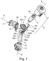
figure 1 est une vue en perspective éclatée de côté d'un mode de réalisation d'un dispositif antivol de l'invention, - les
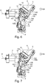
figures 2 à 7 sont des vues en perspective de côté du mode de réalisation de lafigure 1 en fonctionnement, - la
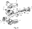
figure 8 est une variante du mode de réalisation de lafigure 2 dans lequel le moyen de retour élastique associé au pêne est un ressort en compression.
- the
figure 1 is an exploded perspective side view of an embodiment of an antitheft device of the invention, - the
Figures 2 to 7 are side perspective views of the embodiment of thefigure 1 Operating, - the
figure 8 is a variant of the embodiment of thefigure 2 wherein the elastic return means associated with the bolt is a spring in compression.
Comme représenté sur la
- un
verrou 2 comprenant :- un
rotor 3 destiné à permettre le démarrage du véhicule automobile, leditrotor 3 s'étendant suivant unaxe 4 sensiblement longitudinal et étant monté mobile en rotation selon ledit axe longitudinal 4 ; ledit rotor comportant un logement (non représenté) apte à recevoir un insert de clé (non représenté), - un
stator 5 destiné à recevoir lerotor 3 et à rester fixe parrapport audit rotor 3, et
- un
- une
came 7 apte à déverrouiller la colonne de direction (non représentée), laditecame 7 étant configurée de sorte à être entraîné en rotation avec lerotor 3 suivant l'axe longitudinal 6. - un
pêne 8 entraîné par laditecame 7 pour prendre une position de blocage de la colonne de direction et une position de déblocage de cette dernière, le pêne s'étend suivant un axe longitudinal 9.
- a
lock 2 comprising:- a
rotor 3 for enabling the motor vehicle to be started, saidrotor 3 extending along a substantiallylongitudinal axis 4 and being rotatably mounted along saidlongitudinal axis 4; said rotor having a housing (not shown) adapted to receive a key insert (not shown), - a
stator 5 for receiving therotor 3 and remaining fixed with respect to saidrotor 3, and
- a
- a
cam 7 adapted to unlock the steering column (not shown), saidcam 7 being configured to be rotated with therotor 3 along thelongitudinal axis 6. - a
bolt 8 driven by saidcam 7 to take a locking position of the steering column and an unlocking position thereof, the bolt extends along alongitudinal axis 9.
Le rotor 3 est ainsi de forme sensiblement allongé selon l'axe longitudinal 4. Ainsi, le rotor 3 peut être de forme sensiblement cylindrique. Selon le mode de réalisation représenté sur les figures, le rotor 3 comporte une ouverture 3a débouchant dans un logement (non représenté) apte à recevoir le moyen d'entraînement (non représenté), tel qu'un insert de clé actionnable par un utilisateur. L'insert de clé peut comporter typiquement une ou plusieurs pistes aptes à déplacer des paillettes (non représentées) disposées longitudinalement dans des ouvertures 3b prévues à cet effet dans le rotor 3 selon l'axe longitudinal 4 de ce dernier. Les paillettes permettent d'empêcher l'introduction d'un insert de clé ne correspondant pas à la combinaison des paillettes du rotor 3 et d'empêcher également la mise en rotation du rotor 3.The
Le stator 5 comporte un logement de forme sensiblement allongé apte à recevoir ledit rotor 3. Le stator 5 est typiquement immobile par rapport au rotor 3.The
La came 7 mobile en rotation selon l'axe longitudinal 8 est apte à être entraînée en rotation par le rotor 3. Selon le mode de réalisation représenté sur les figures, un moyen d'engrenage 10, tel qu'un pignon, peut être intercalé entre la came 7 et l'extrémité du rotor 3. Le pignon 10 comporte typiquement une denture 10a apte à venir coopérer avec une denture 11 présente sur l'extrémité 12 de la came.The
L'organe rotatif 7 peut être une came de toute forme, notamment sensiblement cylindrique.The
Le pêne 8 est entraîné par ladite came 7 pour prendre une position de blocage de la colonne de direction et une position de déblocage de cette dernière. Le pêne s'étend suivant un axe longitudinal 9 et est reçu dans le logement 14 d'un boîtier 13 destiné à protéger le mouvement du pêne.The
Typiquement, le pêne 8 a un mouvement de translation suivant l'axe longitudinal 9 afin de venir bloquer et débloquer la colonne de direction. La colonne de direction peut ainsi comporter un ou plusieurs logements aptes à recevoir l'extrémité du pêne 8.Typically, the
Le pêne 8 est associé à un moyen de retour élastique 108, notamment un ressort en compression (voir
Dans le cas d'un ressort en torsion, l'extrémité libre 108a est configurée pour venir se mettre en compression sous un plot 107 du pêne distinct du plot 15 s'engageant sur le profil de came 16
Dans le cas d'un ressort en compression, l'extrémité libre 108a est configurée pour venir se mettre directement contre la face du pêne 8.In the case of a torsion spring, the
In the case of a spring in compression, the
La came 7 entraîne le pêne 8 par l'intermédiaire d'un plot 15 disposé sur la surface du pêne 8 en regard de la came 7 qui est capable de suivre le profil de la came 7. Ainsi lorsque le verrou 2 est déverrouillé soit par la rotation de l'insert de clé conforme introduit dans le logement du rotor 4, le pêne 8 libère la mobilité de la colonne de direction permettant à l'utilisateur de pouvoir agir sur les roues du véhicule automobile.The
Comme visible sur la
La came 7 présente un profil de came 16 non circulaire afin de permettre la translation du pêne 8 entre la position de blocage et la position de déblocage de la colonne de direction.The
Le dispositif 1 de l'invention comprend également un dispositif de maintien 100 du pêne configuré pour détecter la présence de l'insert de clé dans le logement par un mouvement entre une position de maintien du pêne 8 dans la position de déblocage lorsque l'insert de clé est dans le logement et une position d'attente dans laquelle le dispositif de maintien est à distance du pêne 8 lorsque l'insert de clé n'est pas dans le logement.The device 1 of the invention also comprises a holding
Le dispositif de maintien 100 comporte une extrémité de maintien 101 configurée pour bloquer le pêne 8 en position de déblocage et une extrémité de contact 102 configurée pour détecter la présence de l'insert de clé.The holding
Le dispositif de maintien 100 est mobile en rotation selon un axe 109 sensiblement perpendiculaire à l'axe longitudinal 4 du verrou. Le dispositif de maintien détectant un insert de clé soit directement par l'extrémité de contact soit indirectement, se met à pivoter autour de l'axe de rotation dudit moyen de maintien 100.The holding
Le verrou 2 comporte un dispositif intermédiaire de détection 121 de la présence d'un insert de clé dans le logement et coopérant avec l'extrémité de contact 102 afin d'entraîner le dispositif de maintien 100 dans disposé dans la position de maintien et la position d'attente.The
Le dispositif de maintien 100 est associé à un moyen de retour élastique 104, notamment un ressort en compression. Le moyen de retour élastique comporte une extrémité 104a fixée à une partie fixe du dispositif antivol de l'invention et une extrémité 104b fixée sur le dispositif de maintien 100.The holding
Le pêne 8 et l'extrémité de maintien 101 du dispositif de blocage sont en contact lors du passage du pêne 8 de la position de blocage à la position de déblocage.The
L'extrémité du pêne 105 en regard de l'extrémité de maintien 101 comporte une rampe 110 sur laquelle vient en appui l'extrémité de maintien lorsque le pêne passe de la position de blocage à la position de déblocage.The end of the
L'extrémité du pêne 105 en regard de l'extrémité de maintien 101 comporte une cavité 106 apte à recevoir l'extrémité de maintien 101.The end of the
L'extrémité de contact 101 présente une forme de crochet destiné à venir dans une cavité 120 du verrou en position d'attente, ladite cavité 120 étant en regard du logement de l'insert de clé.The
L'extrémité de contact 102 est configurée pour venir en position d'attente dans la cavité 120 du verrou 2.The
Au moins une partie du dispositif intermédiaire 121 de détection est reçu dans la cavité 120.At least a portion of the
La cinématique en fonctionnement va être maintenant décrite plus en détail.The kinematics in operation will now be described in more detail.
Comme représenté sur la
Comme représenté sur la
Comme représenté sur les
Comme représenté sur la
Le pêne 8 est donc bloqué dans cette position.The
Comme représenté sur la
Claims (11)
- An antitheft device (1) for a steering column, in particular of a motor vehicle, comprising:- a lock (2) comprising a rotor (3) movable in rotation about an axis of rotation (4) extending according to its longitudinal axis and housed within a stator (5) fixed relative to the rotor (3), said rotor (3) including a housing adapted to receive a key insert,- a cam (7) configured to be controlled by said rotor (3),- a bolt (8) driven by said cam (7) to take on a blocking position of the steering column and an unblocking position of the latter, and- a device (100) for holding the bolt (8) being configured to detect the presence of the key insert in the housing by a movement between a holding position of the bolt (8) in the unblocking position when the key insert is in the housing and a standby position in which the holding device (100) is away from the bolt (8) when the key insert is not in the housing,
wherein the longitudinal axes (9, 6, 4) of the bolt (8), of the cam (7) and of the rotor (3) are coplanar and non-collinear. - The device (1) according to claim 1, wherein the holding device (100) includes a holding end (101) configured to block the bolt (8) in the unblocking position and a contact end (102) configured to detect the presence of the key insert.
- The device (1) according to claim 1 or 2, wherein the lock (2) includes an intermediate device (121) for detecting the presence of a key insert in the housing and cooperating with the contact end (102) in order to drive the holding device (100) into the holding position and the standby position.
- The device (1) according to the preceding claim, wherein the intermediate detection device (121) is associated with an elastic return means.
- The device (1) according to any one of claims 2 to 4, wherein the bolt (8) and the holding end (101) of the blocking device are in contact during the passage of the bolt (8) from the blocking position to the unblocking position.
- The device (1) according to any one of claims 2 to 5, wherein the end (105) of the bolt opposite the holding end (101) includes a ramp (110) on which the holding end (101) bears when the bolt (8) passes from the blocking position to the unblocking position.
- The device (1) according to any one of claims 2 to 6, wherein the end (105) of the bolt opposite the holding end (101) includes a cavity (106) adapted to receive the holding end (101).
- The device (1) according to any one of claims 2 to 7, wherein the contact end (102) has a hook shape intended to come into a cavity of the lock (2) in the standby position, said cavity being opposite the housing of the key insert.
- The device (1) according to any one of claims 2 to 8, wherein the contact end (102) is configured to come into the standby position in the cavity of the lock (2).
- The device (1) according to claim 4 considered together with claims 8 or 9, wherein at least one portion of the intermediate detection device (121) is received in the cavity (120) of the lock.
- A motor vehicle including a steering column and an antitheft device (1) according to any one of the preceding claims.
Applications Claiming Priority (2)
| Application Number | Priority Date | Filing Date | Title |
|---|---|---|---|
| FR1462840A FR3030407B1 (en) | 2014-12-18 | 2014-12-18 | ANTI-THEFT DEVICE FOR STEERING COLUMN |
| PCT/EP2015/078092 WO2016096389A1 (en) | 2014-12-18 | 2015-11-30 | Antitheft device for steering column |
Publications (2)
| Publication Number | Publication Date |
|---|---|
| EP3233587A1 EP3233587A1 (en) | 2017-10-25 |
| EP3233587B1 true EP3233587B1 (en) | 2019-09-18 |
Family
ID=53039523
Family Applications (1)
| Application Number | Title | Priority Date | Filing Date |
|---|---|---|---|
| EP15801863.0A Active EP3233587B1 (en) | 2014-12-18 | 2015-11-30 | Antitheft device for steering column |
Country Status (5)
| Country | Link |
|---|---|
| EP (1) | EP3233587B1 (en) |
| JP (1) | JP6666914B2 (en) |
| CN (1) | CN107000684B (en) |
| FR (1) | FR3030407B1 (en) |
| WO (1) | WO2016096389A1 (en) |
Family Cites Families (7)
| Publication number | Priority date | Publication date | Assignee | Title |
|---|---|---|---|---|
| IT985971B (en) * | 1973-05-28 | 1974-12-30 | Arman D Sas | IMPROVEMENT RELATING TO ANTI-THEFT DEVICES, STEERING LOCK AND RELATIVE ELECTRICAL SWITCHES FOR MOTOR VEHICLES |
| IT1118347B (en) * | 1979-02-13 | 1986-02-24 | Arman Spa | STEERING LOCK ANTI-THEFT DEVICE FOR VEHICLES |
| JPS6012765Y2 (en) * | 1979-07-02 | 1985-04-24 | 株式会社東海理化電機製作所 | car key cylinder |
| JP4226186B2 (en) * | 2000-03-14 | 2009-02-18 | 株式会社ホンダロック | Steering lock device |
| DE102010038160A1 (en) * | 2010-10-13 | 2012-04-19 | Huf Hülsbeck & Fürst Gmbh & Co. Kg | Device for shifting a blocking element |
| FR2974777B1 (en) * | 2011-05-03 | 2015-02-20 | Valeo Securite Habitacle | ANTI-THEFT DEVICE FOR STEERING COLUMN AND STEERING COLUMN THEREFOR |
| DE102012012929A1 (en) * | 2012-06-29 | 2014-04-24 | Huf Hülsbeck & Fürst Gmbh & Co. Kg | Mechanical steering lock |
-
2014
- 2014-12-18 FR FR1462840A patent/FR3030407B1/en not_active Expired - Fee Related
-
2015
- 2015-11-30 JP JP2017531556A patent/JP6666914B2/en active Active
- 2015-11-30 EP EP15801863.0A patent/EP3233587B1/en active Active
- 2015-11-30 CN CN201580068760.9A patent/CN107000684B/en active Active
- 2015-11-30 WO PCT/EP2015/078092 patent/WO2016096389A1/en active Application Filing
Non-Patent Citations (1)
| Title |
|---|
| None * |
Also Published As
| Publication number | Publication date |
|---|---|
| FR3030407B1 (en) | 2018-04-27 |
| JP6666914B2 (en) | 2020-03-18 |
| FR3030407A1 (en) | 2016-06-24 |
| CN107000684B (en) | 2020-06-23 |
| JP2018500231A (en) | 2018-01-11 |
| EP3233587A1 (en) | 2017-10-25 |
| WO2016096389A1 (en) | 2016-06-23 |
| CN107000684A (en) | 2017-08-01 |
Similar Documents
| Publication | Publication Date | Title |
|---|---|---|
| EP3404176B1 (en) | Device for unlocking a door latch | |
| FR2679504A1 (en) | VEHICLE STEERING LOCK. | |
| EP2121392B1 (en) | Anti-theft security device for vehicles | |
| FR2970680A1 (en) | Side door for vehicle, has control unit comprising end connected to body of external control device and another end connected to locking unit, where locking unit, in locking position, cooperates with lever to lock lever in rest position | |
| EP3060438B1 (en) | Antitheft for a motor vehicle steering column | |
| FR3061227B1 (en) | MULTIFUNCTIONAL MODULE FOR SLIDING LOUVOYANTE DOOR, AND VEHICLE THUS EQUIPPED | |
| EP3034723A1 (en) | Lock for a door of a motor vehicle | |
| EP3233587B1 (en) | Antitheft device for steering column | |
| EP2736772B1 (en) | Anti-theft device for a steering column and associated steering column | |
| EP3032010B1 (en) | Lock for a door of a motor vehicle | |
| EP0906997A1 (en) | Locking device comprising a cam operated transmission element | |
| EP2565353A1 (en) | Locking and unlocking device using a key of a buffer on a frame with integral cap for closing an opening of the buffer for inserting the key | |
| WO2008078017A1 (en) | Sector in a parking brake device | |
| EP3233590B1 (en) | Steering column lock for a motor vehicle | |
| EP1637676A2 (en) | Door grip and mounting method of the same | |
| WO2014202549A1 (en) | Steering column anti-theft device | |
| FR3077836A1 (en) | PREVENTION SYSTEM AGAINST UNINTENDED OPENING OF A STORAGE DEVICE IN THE EVENT OF SHOCK. | |
| EP2503082B1 (en) | Motorisiertes Schloss für Kraftfahrzeug | |
| EP1882807B1 (en) | Control device for a disengaging unit of an electric actuator | |
| EP1657380A1 (en) | Actuator device for a wing deadlock mechanism with press-in handle and wing equipped with such a device | |
| EP0940530A1 (en) | Locking device for a wing on a vehicle comprising a pivoting element, which can be slid to an uncoupling position and which is actuated by a cam | |
| EP2736773A1 (en) | Anti-theft device for the steering column of a motor vehicle | |
| EP4321713A1 (en) | Locking device for a vehicle door | |
| FR2618119A3 (en) | TWO-WHEELED VEHICLE WITH DEVICE FOR LOCKING AN OBJECT, IN PARTICULAR A HELMET, ON THE STRUCTURE OF THE VEHICLE | |
| FR2657828A1 (en) | Antitheft device for locking the steering of motor vehicles |
Legal Events
| Date | Code | Title | Description |
|---|---|---|---|
| STAA | Information on the status of an ep patent application or granted ep patent |
Free format text: STATUS: THE INTERNATIONAL PUBLICATION HAS BEEN MADE |
|
| PUAI | Public reference made under article 153(3) epc to a published international application that has entered the european phase |
Free format text: ORIGINAL CODE: 0009012 |
|
| STAA | Information on the status of an ep patent application or granted ep patent |
Free format text: STATUS: REQUEST FOR EXAMINATION WAS MADE |
|
| 17P | Request for examination filed |
Effective date: 20170703 |
|
| AK | Designated contracting states |
Kind code of ref document: A1 Designated state(s): AL AT BE BG CH CY CZ DE DK EE ES FI FR GB GR HR HU IE IS IT LI LT LU LV MC MK MT NL NO PL PT RO RS SE SI SK SM TR |
|
| AX | Request for extension of the european patent |
Extension state: BA ME |
|
| DAV | Request for validation of the european patent (deleted) | ||
| DAX | Request for extension of the european patent (deleted) | ||
| GRAP | Despatch of communication of intention to grant a patent |
Free format text: ORIGINAL CODE: EPIDOSNIGR1 |
|
| STAA | Information on the status of an ep patent application or granted ep patent |
Free format text: STATUS: GRANT OF PATENT IS INTENDED |
|
| INTG | Intention to grant announced |
Effective date: 20190410 |
|
| GRAS | Grant fee paid |
Free format text: ORIGINAL CODE: EPIDOSNIGR3 |
|
| GRAA | (expected) grant |
Free format text: ORIGINAL CODE: 0009210 |
|
| STAA | Information on the status of an ep patent application or granted ep patent |
Free format text: STATUS: THE PATENT HAS BEEN GRANTED |
|
| AK | Designated contracting states |
Kind code of ref document: B1 Designated state(s): AL AT BE BG CH CY CZ DE DK EE ES FI FR GB GR HR HU IE IS IT LI LT LU LV MC MK MT NL NO PL PT RO RS SE SI SK SM TR |
|
| REG | Reference to a national code |
Ref country code: GB Ref legal event code: FG4D Free format text: NOT ENGLISH |
|
| REG | Reference to a national code |
Ref country code: CH Ref legal event code: EP |
|
| REG | Reference to a national code |
Ref country code: DE Ref legal event code: R096 Ref document number: 602015038355 Country of ref document: DE |
|
| REG | Reference to a national code |
Ref country code: AT Ref legal event code: REF Ref document number: 1180910 Country of ref document: AT Kind code of ref document: T Effective date: 20191015 |
|
| REG | Reference to a national code |
Ref country code: IE Ref legal event code: FG4D Free format text: LANGUAGE OF EP DOCUMENT: FRENCH |
|
| REG | Reference to a national code |
Ref country code: NL Ref legal event code: MP Effective date: 20190918 |
|
| PG25 | Lapsed in a contracting state [announced via postgrant information from national office to epo] |
Ref country code: HR Free format text: LAPSE BECAUSE OF FAILURE TO SUBMIT A TRANSLATION OF THE DESCRIPTION OR TO PAY THE FEE WITHIN THE PRESCRIBED TIME-LIMIT Effective date: 20190918 Ref country code: SE Free format text: LAPSE BECAUSE OF FAILURE TO SUBMIT A TRANSLATION OF THE DESCRIPTION OR TO PAY THE FEE WITHIN THE PRESCRIBED TIME-LIMIT Effective date: 20190918 Ref country code: FI Free format text: LAPSE BECAUSE OF FAILURE TO SUBMIT A TRANSLATION OF THE DESCRIPTION OR TO PAY THE FEE WITHIN THE PRESCRIBED TIME-LIMIT Effective date: 20190918 Ref country code: NO Free format text: LAPSE BECAUSE OF FAILURE TO SUBMIT A TRANSLATION OF THE DESCRIPTION OR TO PAY THE FEE WITHIN THE PRESCRIBED TIME-LIMIT Effective date: 20191218 Ref country code: BG Free format text: LAPSE BECAUSE OF FAILURE TO SUBMIT A TRANSLATION OF THE DESCRIPTION OR TO PAY THE FEE WITHIN THE PRESCRIBED TIME-LIMIT Effective date: 20191218 Ref country code: LT Free format text: LAPSE BECAUSE OF FAILURE TO SUBMIT A TRANSLATION OF THE DESCRIPTION OR TO PAY THE FEE WITHIN THE PRESCRIBED TIME-LIMIT Effective date: 20190918 |
|
| REG | Reference to a national code |
Ref country code: LT Ref legal event code: MG4D |
|
| PG25 | Lapsed in a contracting state [announced via postgrant information from national office to epo] |
Ref country code: RS Free format text: LAPSE BECAUSE OF FAILURE TO SUBMIT A TRANSLATION OF THE DESCRIPTION OR TO PAY THE FEE WITHIN THE PRESCRIBED TIME-LIMIT Effective date: 20190918 Ref country code: LV Free format text: LAPSE BECAUSE OF FAILURE TO SUBMIT A TRANSLATION OF THE DESCRIPTION OR TO PAY THE FEE WITHIN THE PRESCRIBED TIME-LIMIT Effective date: 20190918 Ref country code: AL Free format text: LAPSE BECAUSE OF FAILURE TO SUBMIT A TRANSLATION OF THE DESCRIPTION OR TO PAY THE FEE WITHIN THE PRESCRIBED TIME-LIMIT Effective date: 20190918 Ref country code: GR Free format text: LAPSE BECAUSE OF FAILURE TO SUBMIT A TRANSLATION OF THE DESCRIPTION OR TO PAY THE FEE WITHIN THE PRESCRIBED TIME-LIMIT Effective date: 20191219 |
|
| REG | Reference to a national code |
Ref country code: AT Ref legal event code: MK05 Ref document number: 1180910 Country of ref document: AT Kind code of ref document: T Effective date: 20190918 |
|
| PG25 | Lapsed in a contracting state [announced via postgrant information from national office to epo] |
Ref country code: PT Free format text: LAPSE BECAUSE OF FAILURE TO SUBMIT A TRANSLATION OF THE DESCRIPTION OR TO PAY THE FEE WITHIN THE PRESCRIBED TIME-LIMIT Effective date: 20200120 Ref country code: NL Free format text: LAPSE BECAUSE OF FAILURE TO SUBMIT A TRANSLATION OF THE DESCRIPTION OR TO PAY THE FEE WITHIN THE PRESCRIBED TIME-LIMIT Effective date: 20190918 Ref country code: ES Free format text: LAPSE BECAUSE OF FAILURE TO SUBMIT A TRANSLATION OF THE DESCRIPTION OR TO PAY THE FEE WITHIN THE PRESCRIBED TIME-LIMIT Effective date: 20190918 Ref country code: PL Free format text: LAPSE BECAUSE OF FAILURE TO SUBMIT A TRANSLATION OF THE DESCRIPTION OR TO PAY THE FEE WITHIN THE PRESCRIBED TIME-LIMIT Effective date: 20190918 Ref country code: RO Free format text: LAPSE BECAUSE OF FAILURE TO SUBMIT A TRANSLATION OF THE DESCRIPTION OR TO PAY THE FEE WITHIN THE PRESCRIBED TIME-LIMIT Effective date: 20190918 Ref country code: AT Free format text: LAPSE BECAUSE OF FAILURE TO SUBMIT A TRANSLATION OF THE DESCRIPTION OR TO PAY THE FEE WITHIN THE PRESCRIBED TIME-LIMIT Effective date: 20190918 Ref country code: IT Free format text: LAPSE BECAUSE OF FAILURE TO SUBMIT A TRANSLATION OF THE DESCRIPTION OR TO PAY THE FEE WITHIN THE PRESCRIBED TIME-LIMIT Effective date: 20190918 Ref country code: EE Free format text: LAPSE BECAUSE OF FAILURE TO SUBMIT A TRANSLATION OF THE DESCRIPTION OR TO PAY THE FEE WITHIN THE PRESCRIBED TIME-LIMIT Effective date: 20190918 |
|
| PG25 | Lapsed in a contracting state [announced via postgrant information from national office to epo] |
Ref country code: SM Free format text: LAPSE BECAUSE OF FAILURE TO SUBMIT A TRANSLATION OF THE DESCRIPTION OR TO PAY THE FEE WITHIN THE PRESCRIBED TIME-LIMIT Effective date: 20190918 Ref country code: CZ Free format text: LAPSE BECAUSE OF FAILURE TO SUBMIT A TRANSLATION OF THE DESCRIPTION OR TO PAY THE FEE WITHIN THE PRESCRIBED TIME-LIMIT Effective date: 20190918 Ref country code: IS Free format text: LAPSE BECAUSE OF FAILURE TO SUBMIT A TRANSLATION OF THE DESCRIPTION OR TO PAY THE FEE WITHIN THE PRESCRIBED TIME-LIMIT Effective date: 20200224 Ref country code: SK Free format text: LAPSE BECAUSE OF FAILURE TO SUBMIT A TRANSLATION OF THE DESCRIPTION OR TO PAY THE FEE WITHIN THE PRESCRIBED TIME-LIMIT Effective date: 20190918 |
|
| REG | Reference to a national code |
Ref country code: DE Ref legal event code: R097 Ref document number: 602015038355 Country of ref document: DE |
|
| REG | Reference to a national code |
Ref country code: CH Ref legal event code: PL |
|
| PLBE | No opposition filed within time limit |
Free format text: ORIGINAL CODE: 0009261 |
|
| STAA | Information on the status of an ep patent application or granted ep patent |
Free format text: STATUS: NO OPPOSITION FILED WITHIN TIME LIMIT |
|
| PG2D | Information on lapse in contracting state deleted |
Ref country code: IS |
|
| PG25 | Lapsed in a contracting state [announced via postgrant information from national office to epo] |
Ref country code: LU Free format text: LAPSE BECAUSE OF NON-PAYMENT OF DUE FEES Effective date: 20191130 Ref country code: MC Free format text: LAPSE BECAUSE OF FAILURE TO SUBMIT A TRANSLATION OF THE DESCRIPTION OR TO PAY THE FEE WITHIN THE PRESCRIBED TIME-LIMIT Effective date: 20190918 Ref country code: DK Free format text: LAPSE BECAUSE OF FAILURE TO SUBMIT A TRANSLATION OF THE DESCRIPTION OR TO PAY THE FEE WITHIN THE PRESCRIBED TIME-LIMIT Effective date: 20190918 Ref country code: LI Free format text: LAPSE BECAUSE OF NON-PAYMENT OF DUE FEES Effective date: 20191130 Ref country code: CH Free format text: LAPSE BECAUSE OF NON-PAYMENT OF DUE FEES Effective date: 20191130 Ref country code: IS Free format text: LAPSE BECAUSE OF FAILURE TO SUBMIT A TRANSLATION OF THE DESCRIPTION OR TO PAY THE FEE WITHIN THE PRESCRIBED TIME-LIMIT Effective date: 20200119 |
|
| REG | Reference to a national code |
Ref country code: BE Ref legal event code: MM Effective date: 20191130 |
|
| 26N | No opposition filed |
Effective date: 20200619 |
|
| PG25 | Lapsed in a contracting state [announced via postgrant information from national office to epo] |
Ref country code: SI Free format text: LAPSE BECAUSE OF FAILURE TO SUBMIT A TRANSLATION OF THE DESCRIPTION OR TO PAY THE FEE WITHIN THE PRESCRIBED TIME-LIMIT Effective date: 20190918 |
|
| GBPC | Gb: european patent ceased through non-payment of renewal fee |
Effective date: 20191218 |
|
| PG25 | Lapsed in a contracting state [announced via postgrant information from national office to epo] |
Ref country code: IE Free format text: LAPSE BECAUSE OF NON-PAYMENT OF DUE FEES Effective date: 20191130 Ref country code: GB Free format text: LAPSE BECAUSE OF NON-PAYMENT OF DUE FEES Effective date: 20191218 |
|
| PG25 | Lapsed in a contracting state [announced via postgrant information from national office to epo] |
Ref country code: BE Free format text: LAPSE BECAUSE OF NON-PAYMENT OF DUE FEES Effective date: 20191130 |
|
| PG25 | Lapsed in a contracting state [announced via postgrant information from national office to epo] |
Ref country code: CY Free format text: LAPSE BECAUSE OF FAILURE TO SUBMIT A TRANSLATION OF THE DESCRIPTION OR TO PAY THE FEE WITHIN THE PRESCRIBED TIME-LIMIT Effective date: 20190918 |
|
| PG25 | Lapsed in a contracting state [announced via postgrant information from national office to epo] |
Ref country code: HU Free format text: LAPSE BECAUSE OF FAILURE TO SUBMIT A TRANSLATION OF THE DESCRIPTION OR TO PAY THE FEE WITHIN THE PRESCRIBED TIME-LIMIT; INVALID AB INITIO Effective date: 20151130 Ref country code: MT Free format text: LAPSE BECAUSE OF FAILURE TO SUBMIT A TRANSLATION OF THE DESCRIPTION OR TO PAY THE FEE WITHIN THE PRESCRIBED TIME-LIMIT Effective date: 20190918 |
|
| PG25 | Lapsed in a contracting state [announced via postgrant information from national office to epo] |
Ref country code: TR Free format text: LAPSE BECAUSE OF FAILURE TO SUBMIT A TRANSLATION OF THE DESCRIPTION OR TO PAY THE FEE WITHIN THE PRESCRIBED TIME-LIMIT Effective date: 20190918 |
|
| PG25 | Lapsed in a contracting state [announced via postgrant information from national office to epo] |
Ref country code: MK Free format text: LAPSE BECAUSE OF FAILURE TO SUBMIT A TRANSLATION OF THE DESCRIPTION OR TO PAY THE FEE WITHIN THE PRESCRIBED TIME-LIMIT Effective date: 20190918 |
|
| REG | Reference to a national code |
Ref country code: DE Ref legal event code: R081 Ref document number: 602015038355 Country of ref document: DE Owner name: RENAULT S.A.S, FR Free format text: FORMER OWNER: U-SHIN FRANCE, CRETEIL, FR |
|
| PGFP | Annual fee paid to national office [announced via postgrant information from national office to epo] |
Ref country code: FR Payment date: 20231124 Year of fee payment: 9 Ref country code: DE Payment date: 20231107 Year of fee payment: 9 |