EP3233152B1 - System und verfahren zur peritonealdialyse - Google Patents
System und verfahren zur peritonealdialyse Download PDFInfo
- Publication number
- EP3233152B1 EP3233152B1 EP15868768.1A EP15868768A EP3233152B1 EP 3233152 B1 EP3233152 B1 EP 3233152B1 EP 15868768 A EP15868768 A EP 15868768A EP 3233152 B1 EP3233152 B1 EP 3233152B1
- Authority
- EP
- European Patent Office
- Prior art keywords
- microprocessor
- pressure
- instructions
- computer
- configure
- Prior art date
- Legal status (The legal status is an assumption and is not a legal conclusion. Google has not performed a legal analysis and makes no representation as to the accuracy of the status listed.)
- Active
Links
- 238000000502 dialysis Methods 0.000 title claims description 23
- 238000000034 method Methods 0.000 title description 41
- 239000012530 fluid Substances 0.000 claims description 61
- 239000000203 mixture Substances 0.000 claims description 13
- 238000009472 formulation Methods 0.000 claims description 12
- 238000009530 blood pressure measurement Methods 0.000 claims description 9
- 230000003287 optical effect Effects 0.000 claims description 9
- 230000002441 reversible effect Effects 0.000 claims description 5
- 238000004891 communication Methods 0.000 claims description 4
- 230000036387 respiratory rate Effects 0.000 claims description 2
- 230000004044 response Effects 0.000 claims description 2
- 238000012544 monitoring process Methods 0.000 description 10
- 238000010923 batch production Methods 0.000 description 9
- 230000008569 process Effects 0.000 description 9
- 230000032258 transport Effects 0.000 description 9
- 238000001914 filtration Methods 0.000 description 8
- 210000004303 peritoneum Anatomy 0.000 description 7
- 230000008859 change Effects 0.000 description 6
- 239000007788 liquid Substances 0.000 description 6
- 210000003200 peritoneal cavity Anatomy 0.000 description 6
- 239000000243 solution Substances 0.000 description 6
- 238000012360 testing method Methods 0.000 description 5
- 239000002699 waste material Substances 0.000 description 5
- 239000008280 blood Substances 0.000 description 4
- 210000004369 blood Anatomy 0.000 description 4
- 238000001631 haemodialysis Methods 0.000 description 4
- 230000000322 hemodialysis Effects 0.000 description 4
- 238000005259 measurement Methods 0.000 description 4
- 210000004379 membrane Anatomy 0.000 description 4
- 239000012528 membrane Substances 0.000 description 4
- 230000029058 respiratory gaseous exchange Effects 0.000 description 4
- WQZGKKKJIJFFOK-GASJEMHNSA-N Glucose Natural products OC[C@H]1OC(O)[C@H](O)[C@@H](O)[C@@H]1O WQZGKKKJIJFFOK-GASJEMHNSA-N 0.000 description 3
- 230000003213 activating effect Effects 0.000 description 3
- 230000008901 benefit Effects 0.000 description 3
- 230000000694 effects Effects 0.000 description 3
- 239000008103 glucose Substances 0.000 description 3
- 230000009471 action Effects 0.000 description 2
- 238000013459 approach Methods 0.000 description 2
- 230000008827 biological function Effects 0.000 description 2
- 238000012512 characterization method Methods 0.000 description 2
- 230000001010 compromised effect Effects 0.000 description 2
- 230000000875 corresponding effect Effects 0.000 description 2
- 238000013461 design Methods 0.000 description 2
- 238000001514 detection method Methods 0.000 description 2
- 238000005516 engineering process Methods 0.000 description 2
- 238000001727 in vivo Methods 0.000 description 2
- 230000036512 infertility Effects 0.000 description 2
- 210000003734 kidney Anatomy 0.000 description 2
- 238000004519 manufacturing process Methods 0.000 description 2
- 230000037361 pathway Effects 0.000 description 2
- 230000009467 reduction Effects 0.000 description 2
- 230000003860 sleep quality Effects 0.000 description 2
- 239000000126 substance Substances 0.000 description 2
- 238000000108 ultra-filtration Methods 0.000 description 2
- 102000003939 Membrane transport proteins Human genes 0.000 description 1
- 108090000301 Membrane transport proteins Proteins 0.000 description 1
- 210000000683 abdominal cavity Anatomy 0.000 description 1
- 238000010521 absorption reaction Methods 0.000 description 1
- 230000004071 biological effect Effects 0.000 description 1
- 230000036760 body temperature Effects 0.000 description 1
- 239000006227 byproduct Substances 0.000 description 1
- 238000004364 calculation method Methods 0.000 description 1
- 208000020832 chronic kidney disease Diseases 0.000 description 1
- 238000012790 confirmation Methods 0.000 description 1
- 230000002596 correlated effect Effects 0.000 description 1
- 230000001351 cycling effect Effects 0.000 description 1
- 230000003247 decreasing effect Effects 0.000 description 1
- 206010012601 diabetes mellitus Diseases 0.000 description 1
- 239000000385 dialysis solution Substances 0.000 description 1
- 230000037213 diet Effects 0.000 description 1
- 235000005911 diet Nutrition 0.000 description 1
- 238000009792 diffusion process Methods 0.000 description 1
- 238000010790 dilution Methods 0.000 description 1
- 239000012895 dilution Substances 0.000 description 1
- 201000000523 end stage renal failure Diseases 0.000 description 1
- 238000002474 experimental method Methods 0.000 description 1
- 238000000605 extraction Methods 0.000 description 1
- 239000000706 filtrate Substances 0.000 description 1
- 230000006870 function Effects 0.000 description 1
- 230000005484 gravity Effects 0.000 description 1
- 238000001802 infusion Methods 0.000 description 1
- 230000000977 initiatory effect Effects 0.000 description 1
- 230000003907 kidney function Effects 0.000 description 1
- 238000013178 mathematical model Methods 0.000 description 1
- 230000009061 membrane transport Effects 0.000 description 1
- 230000037323 metabolic rate Effects 0.000 description 1
- 230000003278 mimic effect Effects 0.000 description 1
- 239000002357 osmotic agent Substances 0.000 description 1
- 230000003204 osmotic effect Effects 0.000 description 1
- 238000013021 overheating Methods 0.000 description 1
- 230000000737 periodic effect Effects 0.000 description 1
- 230000000704 physical effect Effects 0.000 description 1
- 229920001296 polysiloxane Polymers 0.000 description 1
- 239000011148 porous material Substances 0.000 description 1
- 239000000047 product Substances 0.000 description 1
- 238000004445 quantitative analysis Methods 0.000 description 1
- 230000003362 replicative effect Effects 0.000 description 1
- 238000011272 standard treatment Methods 0.000 description 1
- 230000001954 sterilising effect Effects 0.000 description 1
- 238000004659 sterilization and disinfection Methods 0.000 description 1
- 230000008685 targeting Effects 0.000 description 1
- 239000003053 toxin Substances 0.000 description 1
- 231100000765 toxin Toxicity 0.000 description 1
- 108700012359 toxins Proteins 0.000 description 1
- 230000007723 transport mechanism Effects 0.000 description 1
Images


Classifications
-
- A—HUMAN NECESSITIES
- A61—MEDICAL OR VETERINARY SCIENCE; HYGIENE
- A61M—DEVICES FOR INTRODUCING MEDIA INTO, OR ONTO, THE BODY; DEVICES FOR TRANSDUCING BODY MEDIA OR FOR TAKING MEDIA FROM THE BODY; DEVICES FOR PRODUCING OR ENDING SLEEP OR STUPOR
- A61M1/00—Suction or pumping devices for medical purposes; Devices for carrying-off, for treatment of, or for carrying-over, body-liquids; Drainage systems
- A61M1/14—Dialysis systems; Artificial kidneys; Blood oxygenators ; Reciprocating systems for treatment of body fluids, e.g. single needle systems for hemofiltration or pheresis
- A61M1/28—Peritoneal dialysis ; Other peritoneal treatment, e.g. oxygenation
- A61M1/282—Operational modes
-
- A—HUMAN NECESSITIES
- A61—MEDICAL OR VETERINARY SCIENCE; HYGIENE
- A61M—DEVICES FOR INTRODUCING MEDIA INTO, OR ONTO, THE BODY; DEVICES FOR TRANSDUCING BODY MEDIA OR FOR TAKING MEDIA FROM THE BODY; DEVICES FOR PRODUCING OR ENDING SLEEP OR STUPOR
- A61M1/00—Suction or pumping devices for medical purposes; Devices for carrying-off, for treatment of, or for carrying-over, body-liquids; Drainage systems
- A61M1/14—Dialysis systems; Artificial kidneys; Blood oxygenators ; Reciprocating systems for treatment of body fluids, e.g. single needle systems for hemofiltration or pheresis
- A61M1/15—Dialysis systems; Artificial kidneys; Blood oxygenators ; Reciprocating systems for treatment of body fluids, e.g. single needle systems for hemofiltration or pheresis with a cassette forming partially or totally the flow circuit for the treating fluid, e.g. the dialysate fluid circuit or the treating gas circuit
- A61M1/153—Dialysis systems; Artificial kidneys; Blood oxygenators ; Reciprocating systems for treatment of body fluids, e.g. single needle systems for hemofiltration or pheresis with a cassette forming partially or totally the flow circuit for the treating fluid, e.g. the dialysate fluid circuit or the treating gas circuit the cassette being adapted for heating or cooling the treating fluid, e.g. the dialysate or the treating gas
-
- A—HUMAN NECESSITIES
- A61—MEDICAL OR VETERINARY SCIENCE; HYGIENE
- A61M—DEVICES FOR INTRODUCING MEDIA INTO, OR ONTO, THE BODY; DEVICES FOR TRANSDUCING BODY MEDIA OR FOR TAKING MEDIA FROM THE BODY; DEVICES FOR PRODUCING OR ENDING SLEEP OR STUPOR
- A61M1/00—Suction or pumping devices for medical purposes; Devices for carrying-off, for treatment of, or for carrying-over, body-liquids; Drainage systems
- A61M1/14—Dialysis systems; Artificial kidneys; Blood oxygenators ; Reciprocating systems for treatment of body fluids, e.g. single needle systems for hemofiltration or pheresis
- A61M1/15—Dialysis systems; Artificial kidneys; Blood oxygenators ; Reciprocating systems for treatment of body fluids, e.g. single needle systems for hemofiltration or pheresis with a cassette forming partially or totally the flow circuit for the treating fluid, e.g. the dialysate fluid circuit or the treating gas circuit
- A61M1/154—Dialysis systems; Artificial kidneys; Blood oxygenators ; Reciprocating systems for treatment of body fluids, e.g. single needle systems for hemofiltration or pheresis with a cassette forming partially or totally the flow circuit for the treating fluid, e.g. the dialysate fluid circuit or the treating gas circuit with sensing means or components thereof
-
- A—HUMAN NECESSITIES
- A61—MEDICAL OR VETERINARY SCIENCE; HYGIENE
- A61M—DEVICES FOR INTRODUCING MEDIA INTO, OR ONTO, THE BODY; DEVICES FOR TRANSDUCING BODY MEDIA OR FOR TAKING MEDIA FROM THE BODY; DEVICES FOR PRODUCING OR ENDING SLEEP OR STUPOR
- A61M1/00—Suction or pumping devices for medical purposes; Devices for carrying-off, for treatment of, or for carrying-over, body-liquids; Drainage systems
- A61M1/14—Dialysis systems; Artificial kidneys; Blood oxygenators ; Reciprocating systems for treatment of body fluids, e.g. single needle systems for hemofiltration or pheresis
- A61M1/15—Dialysis systems; Artificial kidneys; Blood oxygenators ; Reciprocating systems for treatment of body fluids, e.g. single needle systems for hemofiltration or pheresis with a cassette forming partially or totally the flow circuit for the treating fluid, e.g. the dialysate fluid circuit or the treating gas circuit
- A61M1/155—Dialysis systems; Artificial kidneys; Blood oxygenators ; Reciprocating systems for treatment of body fluids, e.g. single needle systems for hemofiltration or pheresis with a cassette forming partially or totally the flow circuit for the treating fluid, e.g. the dialysate fluid circuit or the treating gas circuit with treatment-fluid pumping means or components thereof
-
- A—HUMAN NECESSITIES
- A61—MEDICAL OR VETERINARY SCIENCE; HYGIENE
- A61M—DEVICES FOR INTRODUCING MEDIA INTO, OR ONTO, THE BODY; DEVICES FOR TRANSDUCING BODY MEDIA OR FOR TAKING MEDIA FROM THE BODY; DEVICES FOR PRODUCING OR ENDING SLEEP OR STUPOR
- A61M1/00—Suction or pumping devices for medical purposes; Devices for carrying-off, for treatment of, or for carrying-over, body-liquids; Drainage systems
- A61M1/14—Dialysis systems; Artificial kidneys; Blood oxygenators ; Reciprocating systems for treatment of body fluids, e.g. single needle systems for hemofiltration or pheresis
- A61M1/15—Dialysis systems; Artificial kidneys; Blood oxygenators ; Reciprocating systems for treatment of body fluids, e.g. single needle systems for hemofiltration or pheresis with a cassette forming partially or totally the flow circuit for the treating fluid, e.g. the dialysate fluid circuit or the treating gas circuit
- A61M1/156—Constructional details of the cassette, e.g. specific details on material or shape
- A61M1/1565—Details of valves
-
- A—HUMAN NECESSITIES
- A61—MEDICAL OR VETERINARY SCIENCE; HYGIENE
- A61M—DEVICES FOR INTRODUCING MEDIA INTO, OR ONTO, THE BODY; DEVICES FOR TRANSDUCING BODY MEDIA OR FOR TAKING MEDIA FROM THE BODY; DEVICES FOR PRODUCING OR ENDING SLEEP OR STUPOR
- A61M1/00—Suction or pumping devices for medical purposes; Devices for carrying-off, for treatment of, or for carrying-over, body-liquids; Drainage systems
- A61M1/14—Dialysis systems; Artificial kidneys; Blood oxygenators ; Reciprocating systems for treatment of body fluids, e.g. single needle systems for hemofiltration or pheresis
- A61M1/15—Dialysis systems; Artificial kidneys; Blood oxygenators ; Reciprocating systems for treatment of body fluids, e.g. single needle systems for hemofiltration or pheresis with a cassette forming partially or totally the flow circuit for the treating fluid, e.g. the dialysate fluid circuit or the treating gas circuit
- A61M1/159—Dialysis systems; Artificial kidneys; Blood oxygenators ; Reciprocating systems for treatment of body fluids, e.g. single needle systems for hemofiltration or pheresis with a cassette forming partially or totally the flow circuit for the treating fluid, e.g. the dialysate fluid circuit or the treating gas circuit specially adapted for peritoneal dialysis
-
- A—HUMAN NECESSITIES
- A61—MEDICAL OR VETERINARY SCIENCE; HYGIENE
- A61M—DEVICES FOR INTRODUCING MEDIA INTO, OR ONTO, THE BODY; DEVICES FOR TRANSDUCING BODY MEDIA OR FOR TAKING MEDIA FROM THE BODY; DEVICES FOR PRODUCING OR ENDING SLEEP OR STUPOR
- A61M1/00—Suction or pumping devices for medical purposes; Devices for carrying-off, for treatment of, or for carrying-over, body-liquids; Drainage systems
- A61M1/14—Dialysis systems; Artificial kidneys; Blood oxygenators ; Reciprocating systems for treatment of body fluids, e.g. single needle systems for hemofiltration or pheresis
- A61M1/28—Peritoneal dialysis ; Other peritoneal treatment, e.g. oxygenation
-
- A—HUMAN NECESSITIES
- A61—MEDICAL OR VETERINARY SCIENCE; HYGIENE
- A61M—DEVICES FOR INTRODUCING MEDIA INTO, OR ONTO, THE BODY; DEVICES FOR TRANSDUCING BODY MEDIA OR FOR TAKING MEDIA FROM THE BODY; DEVICES FOR PRODUCING OR ENDING SLEEP OR STUPOR
- A61M2205/00—General characteristics of the apparatus
- A61M2205/12—General characteristics of the apparatus with interchangeable cassettes forming partially or totally the fluid circuit
- A61M2205/127—General characteristics of the apparatus with interchangeable cassettes forming partially or totally the fluid circuit with provisions for heating or cooling
-
- A—HUMAN NECESSITIES
- A61—MEDICAL OR VETERINARY SCIENCE; HYGIENE
- A61M—DEVICES FOR INTRODUCING MEDIA INTO, OR ONTO, THE BODY; DEVICES FOR TRANSDUCING BODY MEDIA OR FOR TAKING MEDIA FROM THE BODY; DEVICES FOR PRODUCING OR ENDING SLEEP OR STUPOR
- A61M2205/00—General characteristics of the apparatus
- A61M2205/33—Controlling, regulating or measuring
- A61M2205/3306—Optical measuring means
-
- A—HUMAN NECESSITIES
- A61—MEDICAL OR VETERINARY SCIENCE; HYGIENE
- A61M—DEVICES FOR INTRODUCING MEDIA INTO, OR ONTO, THE BODY; DEVICES FOR TRANSDUCING BODY MEDIA OR FOR TAKING MEDIA FROM THE BODY; DEVICES FOR PRODUCING OR ENDING SLEEP OR STUPOR
- A61M2205/00—General characteristics of the apparatus
- A61M2205/33—Controlling, regulating or measuring
- A61M2205/3331—Pressure; Flow
- A61M2205/3344—Measuring or controlling pressure at the body treatment site
-
- A—HUMAN NECESSITIES
- A61—MEDICAL OR VETERINARY SCIENCE; HYGIENE
- A61M—DEVICES FOR INTRODUCING MEDIA INTO, OR ONTO, THE BODY; DEVICES FOR TRANSDUCING BODY MEDIA OR FOR TAKING MEDIA FROM THE BODY; DEVICES FOR PRODUCING OR ENDING SLEEP OR STUPOR
- A61M2205/00—General characteristics of the apparatus
- A61M2205/33—Controlling, regulating or measuring
- A61M2205/3368—Temperature
Definitions
- the present invention relates generally to dialysis systems and methods. More particularly, it relates to an improved peritoneal dialysis (PD) system, apparatus and methods for use therewith.
- PD peritoneal dialysis
- dialysis is the standard treatment for replicating the function of a normal human kidney.
- dialysis procedures There are two types of dialysis procedures in use, hemodialysis (HD), which circulates the patient's blood through filters located outside the body, and peritoneal dialysis (PD), which uses the peritoneal membrane of the patient's abdominal cavity as a filter to remove toxins via specialized solutions called dialysates.
- HD hemodialysis
- PD peritoneal dialysis
- PD is a very gentle modality, with its slow corrective action more resembling that of the natural kidney. It is operationally simple, eliminates the need for venipunctures and has lower operational costs. Because the system is not an extracorporeal one, there is no need for a high degree of heparinization, a factor that is especially important in the case of diabetic patients. However, to date HD has continued to dominate in the treatment of End-Stage Renal Disease (ESRD) patients.
- ESRD End-Stage Renal Disease
- APD Automatic Peritoneal Dialysis
- CCPD Continuous Cycling Peritoneal Dialysis
- IPD Intermittent Peritoneal Dialysis
- NPD Nightly Peritoneal Dialysis
- TPD Tidal Peritoneal Dialysis
- This modality utilizes an initial maximum dialysate fill volume (usually three liters) and periodically, during a long and continuous dwell time, drains a fraction of the infused volume (usually one-third, the tidal volume and known as the Tidal exchange volume) and re-infuses about a similar amount, adjusting for the UF into the patient. Since there may always be fluid present in the cavity, UF occurs during the Drain and subsequent Fill phases. This additional UF adds to that which occurred during the normal Dwell. The net effect is an increase of the effective "Dwell" time, a positive outcome since the Dwell is when the treatment is at its optimum. This methodology ensures that the quality of the dialysis is kept as high as practical within the limitation of the practiced art and that the effective treatment time (Dwell time) is maximized.
- TPD consumes more dialysate than any of the other mentioned modalities therefore its cost is higher.
- the benefit of this additional cost is the potential to reduce pain events since the cavity is only completely emptied once during the treatment. In the other modalities the cavity is emptied multiple times in a treatment and due to the basic nature of prior Drain algorithms, multiple pain events have been recorded during a full treatment.
- EP0498382 describes a device that can be used for TPD.
- the dialysate parameters do not vary and there is no evidence-based method to determine when to perform a Tidal exchange.
- the frequency and volume exchanged are constant, but the residual volume in the cavity increases over time. This increase in volume was not programmed but is due to the UF that is generated.
- U.S. Patent No. 8,585,634 B2 to Neftel reports a TPD methodology that suggest evidence based exchange times where a mathematical model predicts the times and volumes required.
- U.S. Patent Publication No. US2012/310056A refines on this model where the inputs rely on either the Personal Dialysis Capacity (PDC) test or the Peritoneal Equilibrium (PET) test. These tests provide transport kinetics of the peritoneum at the time of the test. However, the transport kinetics vary from day to day and cycle by cycle. Moreover the patient's diet and current clinical condition at the time of treatment also affects transport kinetics.
- PDC Personal Dialysis Capacity
- PET Peritoneal Equilibrium
- the numbers generated by such test are only the predicted or expected real time transport properties of the peritoneum at the time of a future treatment. In short they do not provide the actual transport kinetics parameters for real time evidence based determination of any of the exchange parameters. These include but are not limited to exchange volume, exchange time and exchange formulation.
- the method selects five individual prescriptions from a suite of possible prescriptions that can generate these curves in accordance to the kinetic model. This method assumes that these five prescriptions meet the individual needs of all patients, which may not be the case since no two patients present identical clinical conditions. The method also assumes that the prescription range is large enough to accommodate any variances that could occur on a daily basis. Furthermore, once the prescription has been initiated no changes can be made during the actual treatment. This method, like in U.S. Publication No. 2012/310056 , cannot determine when the cavity is truly empty. Therefore, a high probability exists that the UF is under-estimated and consequently at the next Last Fill the actual volume in the cavity is higher than what is programmed. This combination leads to the clinically dangerous "overfill condition" for the patient.
- WO 99/06082 A1 discloses an APO system comprising a cassette with a heated region and a sensor region with a pressure sensor, a volumetric pump which supplies fluid to and from the cassette, a valve manifold that connects the cassette with the dialysate solution bags, the patient line and the drain line, wherein the system is under the control of a microprocessor.
- This system carries out pressure measurements in order to maintain the pressure in the patient cavity constant, but it does not differentiate between UF-related pressure changes and pressure changes related to other events, such as patient movements.
- Dadson assumes that the only pressure rise is due to UF production. This is not the case. For example, patient movement during the night can generate abrupt and large swings in pressure. Also, normal biological functions are superimposed on any observable pressure changes.
- the method proposed by Dadson gradually reduces the volume of dialysate in the cavity during the Dwell each time the pressure increases beyond some threshold. Dialysate is removed from the cavity and there is no indication of how to replenish this quantity, which is a requirement in TPD. It is desirable to maintain the Dwell volume at the original Fill value and also supply fresh supply dialysate to compensate for the natural dilution by the UF and in an extreme case, Dadson could prematurely empty the cavity. Failure to account and accommodate for these issues prevents Dadson from performing evidence-based Tidal exchange points.
- a system of measuring a volume of a patient cavity for peritoneal dialysis comprises a cassette having a heated region and a sensor region.
- the sensor region measures pressure measurements.
- the system also comprises a volumetric pump supplying a fluid from one or more bags to the cassette or extracting the fluid from the cassette.
- a patient connection is in fluid communication with the cassette by way of a valve manifold.
- a microprocessor communicates with the sensor region and controls the heated region, the valve manifold, and the volumetric pump. The microprocessor reads and executes instructions from a computer-readable memory.
- the instructions involve: activating the volumetric pump to deliver discrete increments of the fluid to the cassette; receiving the pressure measurements from the sensor region; filtering rapid fluctuations in the pressure measurements to determine an accumulated pressure in the patient cavity; and correlating the accumulated pressure to the volume of the fluid in the patient cavity.
- the instructions may also measure the accumulated pressure and determine a volume of the patient cavity that induces physical discomfort.
- the instructions may also correlate the determination of the volume of the patient cavity to a full cavity condition.
- the instructions may also isolate pressure changes due to an ultrafiltrate (UF) volume increase from the accumulated pressure.
- UF ultrafiltrate
- the instructions may determine a Tidal exchange point based on the isolated pressure changes.
- the accumulated pressure in the patient cavity may be monitored until it reaches a minimum cycle pressure, then the volumetric pump may be activated to deliver discrete increments of the fluid to the cassette until the patient cavity again reaches the full cavity condition.
- the instructions may initiate a Drain phase based on the isolated pressure changes.
- the volumetric pump may reverse to reduce the accumulated pressure in the patient cavity until an empty condition occurs.
- instructions to isolate and/or record pressure changes due to a respiratory rate; heart rate; or determine sleep characteristics may also be instructions to determine transport kinetics based on at least one characteristic of the UF volume increase.
- a computer-implemented method of measuring a volume of a patient cavity for peritoneal dialysis may comprise activating a volumetric pump to deliver discrete increments of a fluid from at least one bag to a cassette or extracting discrete increments of the fluid from the cassette; the cassette in fluid communication with the patient cavity by way of a valve manifold; measuring pressure measurements from a sensor region of the cassette; filtering rapid fluctuations in the pressure measurements to determine an accumulated pressure in the patient cavity; and correlating the accumulated pressure to the volume of the fluid in the patient cavity.
- the method may also comprise steps of measuring the accumulated pressure and determining a volume of the patient cavity that induces physical stress that causes discomfort. The determination of physical stress may be correlated to a full cavity condition.
- the computer-implemented method may comprise at least one of the steps of: isolating pressure changes due to ultrafiltrate (UF) volume increase from the accumulated pressure; determining a Tidal exchange point based on the isolated pressure changes; reversing the volumetric pump to reduce the accumulated pressure in the patient cavity; and monitoring the accumulated pressure in the patient cavity until it reaches a minimum cycle pressure; and activating the volumetric pump to deliver discrete increments of the fluid to the cassette until the patient cavity again reaches the full cavity condition.
- UF ultrafiltrate
- a computer-implemented method that comprises the steps of initiating a Drain phase based on the isolated pressure changes.
- the Drain phase may comprise reversing the volumetric pump to reduce the accumulated pressure in the patient cavity and reducing the accumulated pressure in the patient cavity until an empty condition occurs.
- the valve manifold may have a plurality of ports each coupled to a different bag from the at least one bag, each bag having a different solution.
- the instructions may dynamically adjust a formulation provided to the patient cavity from the different bags.
- the sensor region may measure optical properties.
- the microprocessor may execute instructions to: receive at least one optical property to detect air in the sensor region; and stop the volumetric pump in response to the detected air.
- the sensor region may measure temperature.
- the microprocessor may execute instructions to: receive the temperature associated with the sensor region and increase or decrease energy to the heated region to maintain a physiological temperature in the sensor region.
- the basic element of the tidal modality has the following components as described herein.
- the system must fill the cavity with a prescribed volume of sterile fluid while ensuring that the entire fluid path remains sterile at all times.
- a fixed portion of that Fill volume is periodically drained and discharged as waste after a prescribed time interval. This time interval is known as the Dwell period and the periodic volumes drained during this prescribed time interval is referred to as the exchange volume.
- the exchange volume is then replaced with a volume less than that which was drained. The difference being what was estimated to be the Ultra Filtrate (UF) generated during the Dwell period. After a set number of Dwell periods the complete contents of the cavity is then drained.
- UF Ultra Filtrate
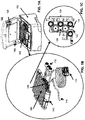
- FIG. 1A to 1C The elements of the multiple modality system 100 are illustrated in Figures 1A to 1C , where a cycler 102 receives a cassette 104 (for example, as disclosed in CA 2,574,537 A1 and WO 2008/086619 A1 ). Fluid path sterility is ensured by the cassette.
- the cassette 104 comprises a heated region 106 and a diagnostic sensor region 108. This fluid-filled sensor region 108 mimics the chemical, physical, and biological properties of the fluid in the peritoneum 150.
- a number of features ensures a sterile environment such as, for example, the system confirms that the cassette 104 is pressure and vacuum tight at the onset of the treatment.
- the system 100 confirms that fluid is flowing freely in the cassette 104 from bags 706 necessary for the prescribed formulation.
- the system 100 detects if any of the fluid lines (112, 114, 116) have unintended flow impediments.
- air is removed from cassette and any sterilization residue is removed as the system 100 performs Flush before Fill on all lines 112, 114, and/or 116.
- the system 100 performs a final confirmation that all fluid paths, in particular 114, contain only sterile fluid and has no air.
- the design and operating principle of this system 100 ensures that no air remains in the patient line 114 prior to the first Fill.
- the fluid pathways are designed such that all fluid movement passes, either to or from the pump 110, over the optical sensor region 124, which is encased by a transmitter-receiver diode pair or other form of optical detector.
- the presence of air instead of liquid in this region 124 defocuses and reduces the light intensity traversing this region 124 resulting in detection of any air in the system by the optical detector. If air is detected in any fluid path, then that fluid path is immediately blocked and the fluid in that path is discarded.
- a volumetric pump 110 supplies pressure or vacuum to the cassette 104 and in this embodiment comprises a piston and cylinder configuration attached to the cassette 104.
- Solution is provided to the cassette 104 by way of solution connections 112 and pump 110.
- a patient connection 114 is connected to the patient in conjunction with a drain 116 by way of a valve manifold 126 having a plurality of ports P1 to P6.
- Figure 1C shows a schematic of the sensor region 108 of a single -use cassette 104 used by the cycler 102.
- the fluid in this region 108 emulates the properties of the fluid in the peritoneum 150. Therefore, measurements taken within this region 108 are indicative of the properties of the fluid in the peritoneum 150.
- the sensor region 108 measures pressure 120, temperature 122, and optical properties 124, but others such as chemical sensors (not shown) could be incorporated.
- the cavity is completely filled with the volume of dialysate that was prescribed by the clinician and at a rate that does not discomfort the patient.
- This fluid should be provided at the prescribed physiological temperature.
- the formulation of this fluid is adjustable at any given exchange point and every effort should be made not to generate by-products by overheating the fluid.
- Pump 110 draws a prescribed volume of fluid from each of the bags connected to 112 in a programmed sequence to generate a fully formulated biocompatible formulation within the body of the pump 110.
- the fluid is prepared and delivered in discrete (0-50mL) increments. Therefore, each increment can be a unique mixture of the solution bags that are attached to ports hence the delivered formulation can be changed at any exchanged point.
- This fluid is then delivered to the patient's cavity by running the pump 110 in reverse.
- the reverse fluid path is such that the fluid must pass over the heated region 106 by way of port P7 and P8 before it reaches the patient's cavity.
- the fluid pathways are designed such that all fluid movement must at some point, either to or from the pump 110, must pass by the optical sensor region 124 which is encased by a transmitter-receiver diode pair. The presence of air instead of liquid in this region 124 defocuses and hence reduces the light intensity traversing this region 124 resulting easy detection of any air in the system. If air is detected in any the fluid path that fluid path is immediately blocked and that fluid is discarded.
- the valve manifold is computer controlled such that only the required port(s) and fluid paths are in communication with the pump for the required filling action. For example, during the filling of the cavity the pump 110 communicates with the cavity via ports P7, P8, and P5. All other ports are isolated from the pump 110.
- the Dwell period represents the most effective portion of the treatment for waste removal. During this time, the majority of the waste is transferred from the blood to the dialysate. Therefore, for optimum performance it is preferable to have an objective manner to determine when this phase is no longer optimal.
- Prior methods and systems use a fixed time for this purpose. The fixed time is not an effective monitor since predetermination of the exact metabolic rate of the patient in advance of the treatment is not possible and therefore a fix dwell period time is inappropriate.
- the embodiment described herein provides an evidence-based method to determine when the Dwell is completed.
- the pump 110 is used to drain the cavity using port P5 and P6 in sequence.
- Port P7 is isolated from the pump 110 by a one-way valve that only allows fluid to pass from the pump 110 to the heated region 106 and never back from the heated region 106 to the pump 110. Therefore, this one-way valve retains sterility of the fluid path by prohibiting fluid leaving the cavity to re-enter the heated region 106.
- the system 100 also recognizes kinks and blockages in lines and distinguishes between air and liquid leaving cavity.
- the system 100 can be positioned such that a gravity drain is permissible in the event of a pump failure.
- the drain algorithm differentiates between an empty cavity and block drain line.
- the present embodiment incorporates pressure monitoring as the objective parameter to improve Tidal modality as described above.
- the pressure sensor 120 measurements in combination with an appropriate algorithm permits the cycler 102 to: isolate pressure changes due only to UF; determine the volume of the cavity; determine when the cavity is full; determine the time when an exchange should be initiated; and determine when the cavity is empty.
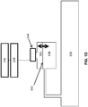
- the force transducer 144 generates a voltage change that is converted from analog to digital and recorded by a microprocessor 148 into memory 146. This data is then digitally filtered by a filtering algorithm in memory 146 executed by the microprocessor 148.
- the filtering algorithm compares the slopes ( dP / dt ) of adjacent data points.
- the UF process is a slow process in comparison to other factors that may increase the cavity pressure. Therefore, if the slope at t + ⁇ t is greater than a given percentage of the value at t , then the detected value at t is discarded as a non-UF pressure rise and an extrapolated value is calculated for t + ⁇ t . This extrapolated value replaces the discarded value. This process is repeated throughout the Dwell period.
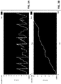
- FIG. 3A and 4A Examples of how the algorithm can separate pressure changes due to ultrafiltration from other events than can cause the cavity pressure to rise as shown in Figures 3 and 4 .
- the top curves shown in Figures 3A and 4A are simulated (enforced) pressure changes.
- the bottom curve shown in Figures 3B and 4B are processed by the algorithm and reported as pressure changes due to UF at the same time increment. This is possible because the timescales associated with pressure due to the enforced UF is long in comparison to pressure changes due to simulated patient movement or biological functions.
- the algorithm monitors pressure during the Dwell by either focusing on pressure increment or rate of change of pressure and differentiates between pressure change due to UF and other sporadic pressure changes.
- the pressure monitoring options comprise at least one of determining when Dwell is complete, reporting on Dwell efficiencies ( d[UF] / dt ) , heart rate monitor, breathing rate, and/or sleep quality option. When reporting on Dwell efficiencies by monitoring and recording the rate of UF increase, characterization of membrane transport properties can be inferred.
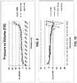
- Figure 5 shows the in-vivo pressure history collected by the on-board pressure sensors 120 during a standard batch process on a patient using this cycler 102.
- the cycler 102 performed as a standard cycle with the ability to monitor and collect data of the pressure in the peritoneal cavity at 30 sec intervals.
- the patient was awake during the treatment and was allowed natural movement, hence the large pressure spikes that were present in Figure 5 coincided with this movement. If such a trace was observed during the night treatment, it would be indicative of the patient's sleep pattern. These large perturbations could be indicative of an underlying clinical issue.
- One such issue is that the patient's breathing may have been compromised.
- Figure 6 demonstrates the effect of incorporating the Dwell algorithm as described above (PR1).
- the new data generated is shown in grey with a trendline shown in light grey.
- Note the average pressure increase in Figure 5 is the same as in Figure 6 but the perturbations due to non-UF pressure changes, such as patient movement has been removed by the Dwell algorithm.
- the cycler 102 may record the pressure changes in the peritoneum 150 that were due only to UF.
- Figure 7 shows the apparatus used to demonstrate how the cycler 102 can be used to measure the cavity volume.
- the "patient cavity" 702 used in Figure 7 was a simulated.
- the simulated patient cavity 702 is constructed to mimic the performance of a real peritoneal cavity.
- the cavity 702 comprises an inner flexible skin bonded by a rigid frame and has the ability to trap air pockets within the inner flexible skin.
- This rigid frame is surrounded by a heater blanket such that the temperature at the interior of the inner skin is kept at body temperature.
- Two inputs tubes were inserted into the cavity 702. The first input tube was terminated by a peritoneal catheter and was inserted into the center of the cavity 702. The second input tube was used as a means to add extra fluid from an independent source (UF reservoir) placed above the patient cavity 702, thus simulating a controlled UF inflow once the appropriate valve was opened.
- UF reservoir independent source
- Figure 8 shows the three locations of the patient cavity 702 height relative to that of the cycler 102.
- the maximum upper and lower ranges were +/-100cm. This was the preset value of the syringe pump that powered the fluid movement. This value could be increased to +/-200cm if required.
- Fluid was admitted to the cavity 702 in each of the three peritoneal cavity positions (-35cm, 0cm, and +35cm) and the pressure recorded in the pressure sensing region 120 was recorded as shown in Figure 9 .
- the inflection point where the inner flexible skin is now being stressed occurs at a similar volume in each case. This stressing of the cavity 702 indicates that the cavity 702 is full. This admitted volume is then the volume of the cavity.
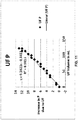
- the UF volume be tracked by monitoring the induced pressure increment. This concept is based on a closed loop fluid path dP / dV being constant.
- the apparatus 700 shown in Figure 7 was used.
- the UF volume was recorded at 1 min time intervals by noting the increase in weight of the cavity 702 which was positioned on a scale. Concurrently to this, the pressure increased in the sensor region of the cycler 102 was recorded.
- the cycler 102 may determine the optimum time in which to terminate the Dwell by monitoring the value of dP / dt. When dP / dt becomes zero, the forward direction of UF is terminated. At this point the Dwell is terminated thus avoiding UF flow reversal.
- the entire UF profile is captured for each cycle. Measuring the entire UF profile for each cycle allows for the direct extraction of the transport rates and the evolution time of each component used in the 3-pore model. Thus individual transport kinetics for each treatment cycle are determined.
- the same experiment was repeated using standard Tidal modality with the measured Fill and Drain volumes generated during the treatment shown in Figure 14 .
- the prescription was an initial Drain, a Fill followed by 7 exchanges, a full drain and then a final Fill.
- the volume of the first fill and the last fill were selected to be the same.
- the measurements that are described herein may not simply be measured, but may also be monitored, tracked, recorded to memory, extracted by way of a USB port 180, streamed over a network to other computer systems at local or remote locations, or discarded.
Landscapes
- Health & Medical Sciences (AREA)
- Heart & Thoracic Surgery (AREA)
- Urology & Nephrology (AREA)
- Emergency Medicine (AREA)
- Anesthesiology (AREA)
- Engineering & Computer Science (AREA)
- Vascular Medicine (AREA)
- Biomedical Technology (AREA)
- Hematology (AREA)
- Life Sciences & Earth Sciences (AREA)
- Animal Behavior & Ethology (AREA)
- General Health & Medical Sciences (AREA)
- Public Health (AREA)
- Veterinary Medicine (AREA)
- External Artificial Organs (AREA)
Claims (16)
- System zur Peritonealdialyse (PD), umfassend:eine Kassette, umfassend eine beheizte Region und eine Sensorregion, wobei die Sensorregion Druckmesswerte misst;eine volumetrische Pumpe, die ein Fluid von mindestens einem Beutel zur Kassette liefert oder das Fluid aus der Kassette extrahiert;einen Patientenanschluss in Fluidaustausch mit der Kassette über einen Ventilverteiler;einen Mikroprozessor, der sich im Austausch mit der Sensorregion befindet und die beheizte Region, den Ventilverteiler und die volumetrische Pumpe steuert;einen computerlesbaren Speicher, wobei der Mikroprozessor Anweisungen aus dem computerlesbaren Speicher liest und ausführt, um den Mikroprozessor zu konfigurieren, um:die volumetrische Pumpe zu aktivieren, diskrete Zuwächse des Fluids an die Kassette zu liefern;die Druckmesswerte aus der Sensorregion zu empfangen;rapide Schwankungen in den Druckmesswerten zu filtern, um einen akkumulierten Druck in der Patientenhöhle zu bestimmen; undden akkumulierten Druck einem Volumen des Fluids in der Patientenhöhle zuzuordnen.
- System nach Anspruch 1, wobei der computerlesbare Speicher ferner Anweisungen umfasst, um den Mikroprozessor zu konfigurieren, um: den akkumulierten Druck zu messen und das Volumen von Fluid in der Patientenhöhle zu bestimmen, das physische Belastung induziert.
- System nach Anspruch 1, wobei der computerlesbare Speicher ferner Anweisungen umfasst, um den Mikroprozessor zu konfigurieren, um: die Bestimmung des Volumens von Fluid in der Patientenhöhle der Bedingung einer vollen Höhle zuzuordnen.
- System nach Anspruch 3, wobei der computerlesbare Speicher ferner Anweisungen umfasst, um den Mikroprozessor zu konfigurieren, um: Druckveränderungen aufgrund einer Erhöhung des Ultrafiltratvolumens (UF-Volumen) aus dem akkumulierten Druck zu isolieren.
- System nach Anspruch 4, wobei der computerlesbare Speicher ferner Anweisungen umfasst, um den Mikroprozessor zu konfigurieren, um: basierend auf den isolierten Druckveränderungen einen Tidal-Austauschpunkt zu bestimmen.
- System nach Anspruch 5, wobei der computerlesbare Speicher ferner Anweisungen umfasst, um den Mikroprozessor zu konfigurieren, um: die volumetrische Pumpe umzukehren, um den akkumulierten Druck in der Patientenhöhle zu reduzieren.
- System nach Anspruch 6, wobei der computerlesbare Speicher ferner Anweisungen umfasst, um den Mikroprozessor zu konfigurieren, um: den akkumulierten Druck in der Patientenhöhle zu überwachen, bis er einen minimalen Zyklusdruck erreicht; und bei dem minimalen Zyklusdruck die volumetrische Pumpe zu aktivieren, um diskrete Zuwächse des Fluids an die Kassette zu liefern, bis die Patientenhöhle die Bedingung der vollen Höhle erreicht.
- System nach Anspruch 4, wobei der computerlesbare Speicher ferner Anweisungen umfasst, um den Mikroprozessor zu konfigurieren, um: basierend auf den isolierten Druckveränderungen eine Drain-Phase zu initiieren.
- System nach Anspruch 8, wobei der computerlesbare Speicher ferner Anweisungen umfasst, um den Mikroprozessor zu konfigurieren, um: die volumetrische Pumpe umzukehren, um den akkumulierten Druck in der Patientenhöhle zu reduzieren.
- System nach Anspruch 9, wobei der computerlesbare Speicher ferner Anweisungen umfasst, um den Mikroprozessor zu konfigurieren, um: den akkumulierten Druck in der Patientenhöhle zu reduzieren, bis eine Leer-Bedingung auftritt.
- System nach einem der Ansprüche 1 bis 10, wobei der Ventilverteiler eine Vielzahl von Anschlüssen umfasst, die jeweils an einen anderen Beutel von dem mindestens einen Beutel gekoppelt sind, wobei jeder Beutel eine andere Lösung aufweist; wobei der computerlesbare Speicher ferner Anweisungen umfasst, um den Mikroprozessor zu konfigurieren, um: eine der Patientenhöhle aus den verschiedenen Beuteln bereitgestellte Formulierung dynamisch anzupassen.
- System nach einem der Ansprüche 1 bis 11, ferner umfassend: die Sensorregion, welche optische Eigenschaften misst; und den computerlesbaren Speicher, ferner umfassend Anweisungen, um den Mikroprozessor zu konfigurieren, um: mindestens eine optische Eigenschaft zu empfangen, um Luft in der Sensorregion zu erkennen; und die volumetrische Pumpe in Reaktion auf die erkannte Luft zu stoppen.
- System nach einem der Ansprüche 1 bis 12, ferner umfassend die Sensorregion, die Temperatur misst; und den computerlesbaren Speicher, ferner umfassend Anweisungen, um den Mikroprozessor zu konfigurieren, um: die der Sensorregion zugeordnete Temperatur zu empfangen und Energie an die beheizte Region zu erhöhen oder zu verringern, um in der Sensorregion eine physiologische Temperatur aufrechtzuerhalten.
- System nach Anspruch 3, wobei der computerlesbare Speicher ferner Anweisungen umfasst, um den Mikroprozessor zu konfigurieren, um: Druckveränderungen aufgrund einer Atemfrequenz zu isolieren.
- System nach einem der Ansprüche 1 bis 14, wobei der computerlesbare Speicher ferner Anweisungen umfasst, um den Mikroprozessor zu konfigurieren, um: Schlafeigenschaften zu bestimmen.
- System nach Anspruch 4, wobei der computerlesbare Speicher ferner Anweisungen umfasst, um den Mikroprozessor zu konfigurieren, um: basierend auf mindestens einer Eigenschaft des UF-Volumenanstiegs Transportkinetik zu bestimmen.
Applications Claiming Priority (2)
| Application Number | Priority Date | Filing Date | Title |
|---|---|---|---|
| US201462092894P | 2014-12-17 | 2014-12-17 | |
| PCT/CA2015/051312 WO2016095026A1 (en) | 2014-12-17 | 2015-12-11 | System and method for peritoneal dialysis |
Publications (3)
| Publication Number | Publication Date |
|---|---|
| EP3233152A1 EP3233152A1 (de) | 2017-10-25 |
| EP3233152A4 EP3233152A4 (de) | 2018-06-06 |
| EP3233152B1 true EP3233152B1 (de) | 2021-02-03 |
Family
ID=56125508
Family Applications (1)
| Application Number | Title | Priority Date | Filing Date |
|---|---|---|---|
| EP15868768.1A Active EP3233152B1 (de) | 2014-12-17 | 2015-12-11 | System und verfahren zur peritonealdialyse |
Country Status (12)
| Country | Link |
|---|---|
| US (1) | US10238784B2 (de) |
| EP (1) | EP3233152B1 (de) |
| JP (1) | JP6727230B2 (de) |
| KR (1) | KR20170102497A (de) |
| CN (1) | CN107206147A (de) |
| AU (1) | AU2015367198B2 (de) |
| BR (1) | BR112017013163B1 (de) |
| CA (1) | CA2971232C (de) |
| ES (1) | ES2869892T3 (de) |
| MX (1) | MX2017008042A (de) |
| SG (1) | SG11201705003XA (de) |
| WO (1) | WO2016095026A1 (de) |
Families Citing this family (13)
| Publication number | Priority date | Publication date | Assignee | Title |
|---|---|---|---|---|
| US9907897B2 (en) | 2011-03-23 | 2018-03-06 | Nxstage Medical, Inc. | Peritoneal dialysis systems, devices, and methods |
| US9061099B2 (en) | 2011-04-29 | 2015-06-23 | Medtronic, Inc. | Cardiovascular monitoring for fluid removal processes |
| US10195418B2 (en) | 2014-10-10 | 2019-02-05 | Nxstage Medical, Inc. | Pinch clamp devices, methods, and systems |
| US10792409B2 (en) | 2015-06-03 | 2020-10-06 | Debiotech S.A. | Peritoneal dialysis treatment system and method of operation |
| US10874790B2 (en) | 2016-08-10 | 2020-12-29 | Medtronic, Inc. | Peritoneal dialysis intracycle osmotic agent adjustment |
| EP3403678A1 (de) * | 2017-05-16 | 2018-11-21 | Fresenius Medical Care Deutschland GmbH | Vorrichtung zur durchführung einer peritonealdialyse |
| US11179516B2 (en) | 2017-06-22 | 2021-11-23 | Baxter International Inc. | Systems and methods for incorporating patient pressure into medical fluid delivery |
| AU2018223035A1 (en) * | 2017-10-03 | 2019-04-18 | Medtronic, Inc. | Peritoneal dialysate temperature regulation system |
| AU2019228526B2 (en) | 2018-02-28 | 2021-11-25 | Nxstage Medical, Inc. | Fluid preparation and treatment devices, methods, and systems |
| CN110237333A (zh) * | 2019-06-20 | 2019-09-17 | 中南大学湘雅医院 | 一种肾内科用腹膜透析装置 |
| US11717600B2 (en) * | 2020-06-04 | 2023-08-08 | Fresenius Medical Care Holdings, Inc. | Administering dialysis treatment using a hybrid automated peritoneal dialysis system |
| CN112618831A (zh) * | 2020-12-23 | 2021-04-09 | 苏州爱力想电子科技有限公司 | 腹透用加热器 |
| US11965763B2 (en) | 2021-11-12 | 2024-04-23 | Mozarc Medical Us Llc | Determining fluid flow across rotary pump |
Family Cites Families (13)
| Publication number | Priority date | Publication date | Assignee | Title |
|---|---|---|---|---|
| IT1170015B (it) * | 1983-12-19 | 1987-06-03 | Sis Ter Sistemi Terapeutici Sp | Apparecchio automatico migliorato di dialisi peritoneale |
| IT1219379B (it) * | 1988-06-15 | 1990-05-11 | Hospal Dasco Spa | Metodo e apparecchiatura per la previsione degli effetti collaterali che si manifestano in un paziente durante un trattamento di dialisi |
| CA2211848C (en) * | 1997-07-28 | 2002-06-11 | Joseph E. Dadson | Peritoneal dialysis apparatus |
| US6497676B1 (en) * | 2000-02-10 | 2002-12-24 | Baxter International | Method and apparatus for monitoring and controlling peritoneal dialysis therapy |
| SE0302698A0 (sv) * | 2003-10-13 | 2005-04-14 | Gambro Lundia Ab | Anordning för genomförande av en peritonealdialysbehandling |
| JP2006218131A (ja) * | 2005-02-10 | 2006-08-24 | Terumo Corp | 腹膜透析装置、透析液セットおよび腹膜透析装置の制御方法 |
| CA2574537C (en) * | 2007-01-19 | 2014-03-25 | Joseph E. Dadson, Sr. | System and method for peritoneal dialysis |
| US7731689B2 (en) * | 2007-02-15 | 2010-06-08 | Baxter International Inc. | Dialysis system having inductive heating |
| US8142649B2 (en) * | 2009-01-29 | 2012-03-27 | Baxter International Inc. | Method for optimizing tidal therapies employing ultrafiltrate trending |
| US9149045B2 (en) * | 2010-12-07 | 2015-10-06 | Kimberly-Clark Worldwide, Inc. | Wipe coated with a botanical emulsion having antimicrobial properties |
| US9907897B2 (en) * | 2011-03-23 | 2018-03-06 | Nxstage Medical, Inc. | Peritoneal dialysis systems, devices, and methods |
| DE102011105916B4 (de) * | 2011-06-29 | 2013-03-28 | Fresenius Medical Care Deutschland Gmbh | Dialysemaschine |
| KR102232652B1 (ko) * | 2012-06-08 | 2021-03-29 | 프레제니우스 메디칼 케어 홀딩스 인코퍼레이티드 | 분할 생체임피던스를 이용하여 복막 투석 동안 초여과 용적을 모니터하고 제어하는 시스템 및 방법 |
-
2015
- 2015-12-11 WO PCT/CA2015/051312 patent/WO2016095026A1/en active Application Filing
- 2015-12-11 JP JP2017550966A patent/JP6727230B2/ja not_active Expired - Fee Related
- 2015-12-11 MX MX2017008042A patent/MX2017008042A/es unknown
- 2015-12-11 EP EP15868768.1A patent/EP3233152B1/de active Active
- 2015-12-11 BR BR112017013163-3A patent/BR112017013163B1/pt active IP Right Grant
- 2015-12-11 ES ES15868768T patent/ES2869892T3/es active Active
- 2015-12-11 CA CA2971232A patent/CA2971232C/en active Active
- 2015-12-11 SG SG11201705003XA patent/SG11201705003XA/en unknown
- 2015-12-11 AU AU2015367198A patent/AU2015367198B2/en not_active Ceased
- 2015-12-11 KR KR1020177019718A patent/KR20170102497A/ko not_active Application Discontinuation
- 2015-12-11 CN CN201580069640.0A patent/CN107206147A/zh active Pending
- 2015-12-11 US US15/537,187 patent/US10238784B2/en active Active
Non-Patent Citations (1)
| Title |
|---|
| None * |
Also Published As
| Publication number | Publication date |
|---|---|
| WO2016095026A1 (en) | 2016-06-23 |
| AU2015367198A1 (en) | 2017-07-06 |
| CN107206147A (zh) | 2017-09-26 |
| AU2015367198B2 (en) | 2019-10-10 |
| SG11201705003XA (en) | 2017-07-28 |
| EP3233152A4 (de) | 2018-06-06 |
| MX2017008042A (es) | 2018-02-09 |
| CA2971232C (en) | 2023-02-28 |
| ES2869892T3 (es) | 2021-10-26 |
| BR112017013163A2 (pt) | 2018-04-10 |
| CA2971232A1 (en) | 2016-06-23 |
| BR112017013163B1 (pt) | 2022-11-22 |
| US20170368249A1 (en) | 2017-12-28 |
| US10238784B2 (en) | 2019-03-26 |
| JP2018505015A (ja) | 2018-02-22 |
| KR20170102497A (ko) | 2017-09-11 |
| EP3233152A1 (de) | 2017-10-25 |
| JP6727230B2 (ja) | 2020-07-22 |
Similar Documents
| Publication | Publication Date | Title |
|---|---|---|
| EP3233152B1 (de) | System und verfahren zur peritonealdialyse | |
| US10744253B2 (en) | Adaptive peritoneal dialysis intra-session adjustments for overall session optimization | |
| KR101862425B1 (ko) | 이동식 한외 여과 장치,관련 방법 및 컴퓨터 프로그램 제품 | |
| JP4070953B2 (ja) | 腹膜透析を行う装置 | |
| EP2988795B1 (de) | Biomedizinische vorrichtung zum pumpen von blut eines patienten oder eines tieres durch einen sekundären intra- oder extrakorporalen blutkreislauf | |
| TW493996B (en) | Tubing for the extracorporal purification of blood | |
| JP6915055B2 (ja) | 保守形態を含む医療流体治療機械 | |
| US10537673B2 (en) | Intersession adaptive peritoneal dialysis fluid removal for multiple session optimization | |
| US20220080117A1 (en) | Systems and methods for incorporating patient pressure into medical fluid delivery | |
| CA2574537C (en) | System and method for peritoneal dialysis | |
| CN110730989B (zh) | 个性化肾衰竭慢性护理系统和方法 | |
| US20220347363A1 (en) | Correlation between intraperitoneal pressure ("ipp") measurements and patient intraperitoneal volume ("ipv") methods, apparatuses, and systems | |
| US20230146216A1 (en) | Peritoneal dialysis cycler having disinfection | |
| EP4046668A1 (de) | Vorrichtung zur extrakorporalen blutbehandlung | |
| JP2023517466A (ja) | 圧力測定値を収集する時を決定するための方法およびデバイス | |
| CN117460454A (zh) | 尿液收集系统及相关方法和装置 | |
| IT202100028082A1 (it) | Apparatus for extracorporeal blood treatment |
Legal Events
| Date | Code | Title | Description |
|---|---|---|---|
| STAA | Information on the status of an ep patent application or granted ep patent |
Free format text: STATUS: THE INTERNATIONAL PUBLICATION HAS BEEN MADE |
|
| PUAI | Public reference made under article 153(3) epc to a published international application that has entered the european phase |
Free format text: ORIGINAL CODE: 0009012 |
|
| STAA | Information on the status of an ep patent application or granted ep patent |
Free format text: STATUS: REQUEST FOR EXAMINATION WAS MADE |
|
| 17P | Request for examination filed |
Effective date: 20170714 |
|
| AK | Designated contracting states |
Kind code of ref document: A1 Designated state(s): AL AT BE BG CH CY CZ DE DK EE ES FI FR GB GR HR HU IE IS IT LI LT LU LV MC MK MT NL NO PL PT RO RS SE SI SK SM TR |
|
| AX | Request for extension of the european patent |
Extension state: BA ME |
|
| RIN1 | Information on inventor provided before grant (corrected) |
Inventor name: BOURNE, ORSON |
|
| DAV | Request for validation of the european patent (deleted) | ||
| DAX | Request for extension of the european patent (deleted) | ||
| A4 | Supplementary search report drawn up and despatched |
Effective date: 20180509 |
|
| RIC1 | Information provided on ipc code assigned before grant |
Ipc: A61M 1/28 20060101AFI20180503BHEP Ipc: A61M 1/36 20060101ALI20180503BHEP Ipc: A61B 5/024 20060101ALI20180503BHEP Ipc: A61B 5/03 20060101ALI20180503BHEP Ipc: A61B 5/08 20060101ALI20180503BHEP |
|
| GRAP | Despatch of communication of intention to grant a patent |
Free format text: ORIGINAL CODE: EPIDOSNIGR1 |
|
| STAA | Information on the status of an ep patent application or granted ep patent |
Free format text: STATUS: GRANT OF PATENT IS INTENDED |
|
| INTG | Intention to grant announced |
Effective date: 20200708 |
|
| GRAS | Grant fee paid |
Free format text: ORIGINAL CODE: EPIDOSNIGR3 |
|
| GRAA | (expected) grant |
Free format text: ORIGINAL CODE: 0009210 |
|
| STAA | Information on the status of an ep patent application or granted ep patent |
Free format text: STATUS: THE PATENT HAS BEEN GRANTED |
|
| AK | Designated contracting states |
Kind code of ref document: B1 Designated state(s): AL AT BE BG CH CY CZ DE DK EE ES FI FR GB GR HR HU IE IS IT LI LT LU LV MC MK MT NL NO PL PT RO RS SE SI SK SM TR |
|
| REG | Reference to a national code |
Ref country code: GB Ref legal event code: FG4D |
|
| REG | Reference to a national code |
Ref country code: AT Ref legal event code: REF Ref document number: 1359560 Country of ref document: AT Kind code of ref document: T Effective date: 20210215 Ref country code: CH Ref legal event code: EP |
|
| REG | Reference to a national code |
Ref country code: DE Ref legal event code: R096 Ref document number: 602015065435 Country of ref document: DE |
|
| REG | Reference to a national code |
Ref country code: IE Ref legal event code: FG4D |
|
| REG | Reference to a national code |
Ref country code: GR Ref legal event code: EP Ref document number: 20210401127 Country of ref document: GR Effective date: 20210614 |
|
| REG | Reference to a national code |
Ref country code: NL Ref legal event code: MP Effective date: 20210203 |
|
| REG | Reference to a national code |
Ref country code: LT Ref legal event code: MG9D |
|
| REG | Reference to a national code |
Ref country code: AT Ref legal event code: MK05 Ref document number: 1359560 Country of ref document: AT Kind code of ref document: T Effective date: 20210203 |
|
| PG25 | Lapsed in a contracting state [announced via postgrant information from national office to epo] |
Ref country code: PT Free format text: LAPSE BECAUSE OF FAILURE TO SUBMIT A TRANSLATION OF THE DESCRIPTION OR TO PAY THE FEE WITHIN THE PRESCRIBED TIME-LIMIT Effective date: 20210604 Ref country code: NO Free format text: LAPSE BECAUSE OF FAILURE TO SUBMIT A TRANSLATION OF THE DESCRIPTION OR TO PAY THE FEE WITHIN THE PRESCRIBED TIME-LIMIT Effective date: 20210503 Ref country code: BG Free format text: LAPSE BECAUSE OF FAILURE TO SUBMIT A TRANSLATION OF THE DESCRIPTION OR TO PAY THE FEE WITHIN THE PRESCRIBED TIME-LIMIT Effective date: 20210503 Ref country code: LT Free format text: LAPSE BECAUSE OF FAILURE TO SUBMIT A TRANSLATION OF THE DESCRIPTION OR TO PAY THE FEE WITHIN THE PRESCRIBED TIME-LIMIT Effective date: 20210203 Ref country code: FI Free format text: LAPSE BECAUSE OF FAILURE TO SUBMIT A TRANSLATION OF THE DESCRIPTION OR TO PAY THE FEE WITHIN THE PRESCRIBED TIME-LIMIT Effective date: 20210203 Ref country code: HR Free format text: LAPSE BECAUSE OF FAILURE TO SUBMIT A TRANSLATION OF THE DESCRIPTION OR TO PAY THE FEE WITHIN THE PRESCRIBED TIME-LIMIT Effective date: 20210203 |
|
| PG25 | Lapsed in a contracting state [announced via postgrant information from national office to epo] |
Ref country code: SE Free format text: LAPSE BECAUSE OF FAILURE TO SUBMIT A TRANSLATION OF THE DESCRIPTION OR TO PAY THE FEE WITHIN THE PRESCRIBED TIME-LIMIT Effective date: 20210203 Ref country code: AT Free format text: LAPSE BECAUSE OF FAILURE TO SUBMIT A TRANSLATION OF THE DESCRIPTION OR TO PAY THE FEE WITHIN THE PRESCRIBED TIME-LIMIT Effective date: 20210203 Ref country code: PL Free format text: LAPSE BECAUSE OF FAILURE TO SUBMIT A TRANSLATION OF THE DESCRIPTION OR TO PAY THE FEE WITHIN THE PRESCRIBED TIME-LIMIT Effective date: 20210203 Ref country code: NL Free format text: LAPSE BECAUSE OF FAILURE TO SUBMIT A TRANSLATION OF THE DESCRIPTION OR TO PAY THE FEE WITHIN THE PRESCRIBED TIME-LIMIT Effective date: 20210203 Ref country code: LV Free format text: LAPSE BECAUSE OF FAILURE TO SUBMIT A TRANSLATION OF THE DESCRIPTION OR TO PAY THE FEE WITHIN THE PRESCRIBED TIME-LIMIT Effective date: 20210203 Ref country code: RS Free format text: LAPSE BECAUSE OF FAILURE TO SUBMIT A TRANSLATION OF THE DESCRIPTION OR TO PAY THE FEE WITHIN THE PRESCRIBED TIME-LIMIT Effective date: 20210203 |
|
| PG25 | Lapsed in a contracting state [announced via postgrant information from national office to epo] |
Ref country code: IS Free format text: LAPSE BECAUSE OF FAILURE TO SUBMIT A TRANSLATION OF THE DESCRIPTION OR TO PAY THE FEE WITHIN THE PRESCRIBED TIME-LIMIT Effective date: 20210603 |
|
| REG | Reference to a national code |
Ref country code: ES Ref legal event code: FG2A Ref document number: 2869892 Country of ref document: ES Kind code of ref document: T3 Effective date: 20211026 |
|
| PG25 | Lapsed in a contracting state [announced via postgrant information from national office to epo] |
Ref country code: CZ Free format text: LAPSE BECAUSE OF FAILURE TO SUBMIT A TRANSLATION OF THE DESCRIPTION OR TO PAY THE FEE WITHIN THE PRESCRIBED TIME-LIMIT Effective date: 20210203 Ref country code: EE Free format text: LAPSE BECAUSE OF FAILURE TO SUBMIT A TRANSLATION OF THE DESCRIPTION OR TO PAY THE FEE WITHIN THE PRESCRIBED TIME-LIMIT Effective date: 20210203 Ref country code: SM Free format text: LAPSE BECAUSE OF FAILURE TO SUBMIT A TRANSLATION OF THE DESCRIPTION OR TO PAY THE FEE WITHIN THE PRESCRIBED TIME-LIMIT Effective date: 20210203 |
|
| REG | Reference to a national code |
Ref country code: DE Ref legal event code: R097 Ref document number: 602015065435 Country of ref document: DE |
|
| PG25 | Lapsed in a contracting state [announced via postgrant information from national office to epo] |
Ref country code: DK Free format text: LAPSE BECAUSE OF FAILURE TO SUBMIT A TRANSLATION OF THE DESCRIPTION OR TO PAY THE FEE WITHIN THE PRESCRIBED TIME-LIMIT Effective date: 20210203 Ref country code: SK Free format text: LAPSE BECAUSE OF FAILURE TO SUBMIT A TRANSLATION OF THE DESCRIPTION OR TO PAY THE FEE WITHIN THE PRESCRIBED TIME-LIMIT Effective date: 20210203 Ref country code: RO Free format text: LAPSE BECAUSE OF FAILURE TO SUBMIT A TRANSLATION OF THE DESCRIPTION OR TO PAY THE FEE WITHIN THE PRESCRIBED TIME-LIMIT Effective date: 20210203 |
|
| PLBE | No opposition filed within time limit |
Free format text: ORIGINAL CODE: 0009261 |
|
| STAA | Information on the status of an ep patent application or granted ep patent |
Free format text: STATUS: NO OPPOSITION FILED WITHIN TIME LIMIT |
|
| 26N | No opposition filed |
Effective date: 20211104 |
|
| PG25 | Lapsed in a contracting state [announced via postgrant information from national office to epo] |
Ref country code: AL Free format text: LAPSE BECAUSE OF FAILURE TO SUBMIT A TRANSLATION OF THE DESCRIPTION OR TO PAY THE FEE WITHIN THE PRESCRIBED TIME-LIMIT Effective date: 20210203 |
|
| PG25 | Lapsed in a contracting state [announced via postgrant information from national office to epo] |
Ref country code: SI Free format text: LAPSE BECAUSE OF FAILURE TO SUBMIT A TRANSLATION OF THE DESCRIPTION OR TO PAY THE FEE WITHIN THE PRESCRIBED TIME-LIMIT Effective date: 20210203 |
|
| PG25 | Lapsed in a contracting state [announced via postgrant information from national office to epo] |
Ref country code: IS Free format text: LAPSE BECAUSE OF FAILURE TO SUBMIT A TRANSLATION OF THE DESCRIPTION OR TO PAY THE FEE WITHIN THE PRESCRIBED TIME-LIMIT Effective date: 20210603 |
|
| PG25 | Lapsed in a contracting state [announced via postgrant information from national office to epo] |
Ref country code: MC Free format text: LAPSE BECAUSE OF FAILURE TO SUBMIT A TRANSLATION OF THE DESCRIPTION OR TO PAY THE FEE WITHIN THE PRESCRIBED TIME-LIMIT Effective date: 20210203 |
|
| REG | Reference to a national code |
Ref country code: CH Ref legal event code: PL |
|
| REG | Reference to a national code |
Ref country code: BE Ref legal event code: MM Effective date: 20211231 |
|
| PG25 | Lapsed in a contracting state [announced via postgrant information from national office to epo] |
Ref country code: LU Free format text: LAPSE BECAUSE OF NON-PAYMENT OF DUE FEES Effective date: 20211211 Ref country code: IE Free format text: LAPSE BECAUSE OF NON-PAYMENT OF DUE FEES Effective date: 20211211 |
|
| PG25 | Lapsed in a contracting state [announced via postgrant information from national office to epo] |
Ref country code: BE Free format text: LAPSE BECAUSE OF NON-PAYMENT OF DUE FEES Effective date: 20211231 |
|
| PG25 | Lapsed in a contracting state [announced via postgrant information from national office to epo] |
Ref country code: LI Free format text: LAPSE BECAUSE OF NON-PAYMENT OF DUE FEES Effective date: 20211231 Ref country code: CH Free format text: LAPSE BECAUSE OF NON-PAYMENT OF DUE FEES Effective date: 20211231 |
|
| PG25 | Lapsed in a contracting state [announced via postgrant information from national office to epo] |
Ref country code: HU Free format text: LAPSE BECAUSE OF FAILURE TO SUBMIT A TRANSLATION OF THE DESCRIPTION OR TO PAY THE FEE WITHIN THE PRESCRIBED TIME-LIMIT; INVALID AB INITIO Effective date: 20151211 |
|
| PG25 | Lapsed in a contracting state [announced via postgrant information from national office to epo] |
Ref country code: CY Free format text: LAPSE BECAUSE OF FAILURE TO SUBMIT A TRANSLATION OF THE DESCRIPTION OR TO PAY THE FEE WITHIN THE PRESCRIBED TIME-LIMIT Effective date: 20210203 |
|
| PGFP | Annual fee paid to national office [announced via postgrant information from national office to epo] |
Ref country code: GB Payment date: 20231220 Year of fee payment: 9 Ref country code: GR Payment date: 20231228 Year of fee payment: 9 |
|
| PGFP | Annual fee paid to national office [announced via postgrant information from national office to epo] |
Ref country code: IT Payment date: 20231227 Year of fee payment: 9 Ref country code: FR Payment date: 20231227 Year of fee payment: 9 |
|
| PGFP | Annual fee paid to national office [announced via postgrant information from national office to epo] |
Ref country code: ES Payment date: 20240129 Year of fee payment: 9 |
|
| PG25 | Lapsed in a contracting state [announced via postgrant information from national office to epo] |
Ref country code: MK Free format text: LAPSE BECAUSE OF FAILURE TO SUBMIT A TRANSLATION OF THE DESCRIPTION OR TO PAY THE FEE WITHIN THE PRESCRIBED TIME-LIMIT Effective date: 20210203 |
|
| PGFP | Annual fee paid to national office [announced via postgrant information from national office to epo] |
Ref country code: DE Payment date: 20231221 Year of fee payment: 9 |