EP3231971A1 - Commercial vehicle, in particular construction vehicle, with a driver's cab with at least one cab door - Google Patents
Commercial vehicle, in particular construction vehicle, with a driver's cab with at least one cab door Download PDFInfo
- Publication number
- EP3231971A1 EP3231971A1 EP17000598.7A EP17000598A EP3231971A1 EP 3231971 A1 EP3231971 A1 EP 3231971A1 EP 17000598 A EP17000598 A EP 17000598A EP 3231971 A1 EP3231971 A1 EP 3231971A1
- Authority
- EP
- European Patent Office
- Prior art keywords
- cab
- door
- actuating
- person
- commercial vehicle
- Prior art date
- Legal status (The legal status is an assumption and is not a legal conclusion. Google has not performed a legal analysis and makes no representation as to the accuracy of the status listed.)
- Granted
Links
- 238000010276 construction Methods 0.000 title claims abstract description 22
- 230000008878 coupling Effects 0.000 claims description 4
- 238000010168 coupling process Methods 0.000 claims description 4
- 238000005859 coupling reaction Methods 0.000 claims description 4
- 238000000465 moulding Methods 0.000 claims description 4
- 230000002411 adverse Effects 0.000 description 2
- 230000000694 effects Effects 0.000 description 2
- 230000007613 environmental effect Effects 0.000 description 2
- 230000000295 complement effect Effects 0.000 description 1
- 238000011161 development Methods 0.000 description 1
- 230000018109 developmental process Effects 0.000 description 1
- 238000000034 method Methods 0.000 description 1
- 238000012544 monitoring process Methods 0.000 description 1
- 230000000007 visual effect Effects 0.000 description 1
Images


Classifications
-
- E—FIXED CONSTRUCTIONS
- E05—LOCKS; KEYS; WINDOW OR DOOR FITTINGS; SAFES
- E05B—LOCKS; ACCESSORIES THEREFOR; HANDCUFFS
- E05B83/00—Vehicle locks specially adapted for particular types of wing or vehicle
- E05B83/36—Locks for passenger or like doors
- E05B83/42—Locks for passenger or like doors for large commercial vehicles, e.g. trucks, construction vehicles or vehicles for mass transport
-
- B—PERFORMING OPERATIONS; TRANSPORTING
- B60—VEHICLES IN GENERAL
- B60J—WINDOWS, WINDSCREENS, NON-FIXED ROOFS, DOORS, OR SIMILAR DEVICES FOR VEHICLES; REMOVABLE EXTERNAL PROTECTIVE COVERINGS SPECIALLY ADAPTED FOR VEHICLES
- B60J5/00—Doors
- B60J5/04—Doors arranged at the vehicle sides
- B60J5/0486—Special type
- B60J5/0487—Special type simplified doors related to cabins of, e.g. golf carts, tractors, jeeps, cranes, forklifts, etc.
-
- E—FIXED CONSTRUCTIONS
- E05—LOCKS; KEYS; WINDOW OR DOOR FITTINGS; SAFES
- E05B—LOCKS; ACCESSORIES THEREFOR; HANDCUFFS
- E05B51/00—Operating or controlling locks or other fastening devices by other non-mechanical means
- E05B51/02—Operating or controlling locks or other fastening devices by other non-mechanical means by pneumatic or hydraulic means
-
- E—FIXED CONSTRUCTIONS
- E05—LOCKS; KEYS; WINDOW OR DOOR FITTINGS; SAFES
- E05B—LOCKS; ACCESSORIES THEREFOR; HANDCUFFS
- E05B53/00—Operation or control of locks by mechanical transmissions, e.g. from a distance
- E05B53/001—Foot-operation
-
- E—FIXED CONSTRUCTIONS
- E05—LOCKS; KEYS; WINDOW OR DOOR FITTINGS; SAFES
- E05B—LOCKS; ACCESSORIES THEREFOR; HANDCUFFS
- E05B53/00—Operation or control of locks by mechanical transmissions, e.g. from a distance
- E05B53/003—Operation or control of locks by mechanical transmissions, e.g. from a distance flexible
-
- E—FIXED CONSTRUCTIONS
- E05—LOCKS; KEYS; WINDOW OR DOOR FITTINGS; SAFES
- E05B—LOCKS; ACCESSORIES THEREFOR; HANDCUFFS
- E05B85/00—Details of vehicle locks not provided for in groups E05B77/00 - E05B83/00
- E05B85/10—Handles
Definitions
- the invention relates to a utility vehicle, in particular a construction vehicle, with a driver's cab having at least one driver's door according to the preamble of claim 1.
- a person, in particular a driver can view and observe the area around the vehicle substantially better than a person standing on the ground next to the vehicle from such an elevated standing position.
- a loading process is well controlled and it can, for example Belade Anlagenn be operated remotely controlled with good visual contact.
- Such elevated standing space can easily be taken on a loading area behind a driver's cab near a cab door.
- such an increased standing space is also provided by the fact that a so-called construction ascent, in particular mounted on a front wheel arch as a tread, optionally in conjunction with a holding device for the hands in the roof area of the cab.
- a person with open cab door In order to get on the tread of a construction climb, a person with open cab door must climb above the cab on the tread. The ascent to a loading area can also be done this way. The descent from the tread of the construction ascent or the loading area is then also about the cab with the cab door open. If the cab door, while the person is on the tread surface of the construction / loading area, has been closed, the lying relatively low down in the foot of the person operating handle of the door lock can not or only very laboriously be operated, so that the person usually debilitating and safety-critical without entry into the cab from the tread down to the floor gymnastics must. Therefore, usually the Cab door left open by a person on the construction ascent, for example, in a monitoring of loading operations.
- the interior of the cab and the door operating modules are exposed to adverse environmental conditions unprotected during this time.
- the interior of the driver's cab cools down adversely when the driver's cab door is open and must first be reheated to save energy when driving on.
- the object of the invention is therefore to equip a commercial vehicle, in particular a construction vehicle, with a cab and with at least one cab door so that a person can easily perform a descent from a construction ramp / loading area even after an activity with the cab door closed with a closed door lock.
- a commercial vehicle in particular a construction vehicle is proposed, with a cab with at least one cab door, and with an elevated standing or standing room for a person, especially on a construction ramp or a cargo area laterally behind the at least one cab door, approximately in the area and / or in the height of an actuating handle of an associated door lock for opening the cab door in the grip area of a person standing next to the vehicle on the ground.
- the door lock for opening the cab door can also be actuated by means of at least one additional actuating means, which is arranged or can be arranged in addition to the actuating handle in the region of the elevated stand.
- this can be done, for example, in such a way that the additional fastening means is arranged or can be arranged at a distance from the actuating handle in the region of the elevated position. Furthermore, this can be done alternatively or additionally, for example, by the additional fastening means being arranged or arrangeable as a supplementary element on the actuating handle itself.
- the door lock for opening the cab door can thus be actuated by a person at the elevated position by means of at least one actuation means which can be easily reached by the person there.
- the person on the elevated stand according to the invention can easily and conveniently operate the door lock of the cab door to open and dismount, it is advantageously possible to close during the dwell time on the elevated stand the cab door to protect the cab interior and the door control modules from environmental influences In particular, the interior of the cab by the shorter opening times of the cab door remains warmer.
- At least one further upper operating handle is arranged for this purpose, in particular in the upper, laterally rear region of the cab door and / or in the rear upper region of the door Cab and thus in the comfortable grip area of a person is placed on the elevated stand.
- Such an additional upper operating handle should be coupled in a functional, cost-effective construction with the lower actuating handle and / or with the opening mechanism of the door lock, preferably mechanically and / or electrically, for a door opening. A person can easily open a cab door with the upper operating handle, even at the elevated stand if necessary.
- a mechanical coupling can be done, for example, with poles and / or cables and / or hydraulically and / or pneumatically.
- An electrical coupling can be done for example by means of controllable electromagnets and / or by means of electromotive actuators.
- actuating means a hand-operated remote control, which is operated at the elevated stand by a person and is coupled by means of radio control with an equipped for a radio control opening mechanism for opening the cab door.
- the locking mechanism can be unlocked in a vehicle door - the vehicle door remains but still closed and must then be opened with the operating handle by hand.
- the (not only) the locking mechanism is to be unlocked with the remote control claimed here, but a total of the door lock in such a way that the cab door jumps at least an opening gap, so that the person on the elevated Stand can grab the cab door and open in total.
- the driver's door can also be opened automatically by means of the remote control using an opening actuator.
- a remote control can be designed either as a portable and thus can be arranged in the region of the elevated stand device that can be taken by a person on the elevated stand, or be there fixed in the grip area on elevated stand.
- the remote control function according to the invention can be integrated as an additional function in known remote controls, such as in a mold control for controlling loading operations.
- an actuating means which is coupled to the actuating handle (in the case of an upper and a lower actuating handle which is preferably the lower actuating handle) and / or with the opening mechanism of the door lock
- at least one foot actuating element in the foot area of a person be provided on the elevated stand.
- such an additional foot actuating element can be arranged approximately at the height of the actuating handle (in the case of an upper and a lower actuating handle, this is preferably the lower actuating handle).
- a foot control element known components, such as a pedal and / or a foot switch may be provided with which the opening mechanism of the door lock, preferably mechanically and / or electrically, as already described above, can be coupled.
- This actuating handle may then have at least one additional molding and / or molding and / or at least one additional attachment for forming the additional actuating means, whereby the actuating handle is supplemented with at least one supplementary element, in particular a bracket and / or a loop, that by means of this Supplementary element in addition to a manual operation and a foot operation, for example, with a toe, from the elevated stand is feasible.
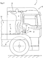
- Fig. 1 is a commercial vehicle 1 as, for example, construction truck in a side view in the area of a cab 2 shown with a closed cab door 3 on the passenger side.
- a (lower) operating handle 4 of an associated door lock is provided to open the cab door 3.
- the lower actuating handle 4 is shown here only as an example as a recessed grip with an outwardly pivotable handle shell.
- the lower operating handle 4 is conveniently located in the upper grip area of a standing next to the commercial vehicle 1 (dashed line) person 7 '.
- the cab 2 shown here is equipped with a so-called construction climb as elevated stand 5 with a tread surface 6 for an elevated person standing 7 and preferably also with a support rod 8 in the roof area of the cab 2.
- the tread surface 6 of the elevated stand 5 is arranged above a front wheel house 9 laterally behind the cab door 3, approximately at the level of the lower operating handle 4. From this elevated stand 5, the person 7 has a good overview, in particular on the area of a loading area 10 in order, for example, to control and control a loading operation.
- the cargo area 10 could also be a shorter cab 2 to be introduced directly behind the cab door 3 (dashed line 22), so that then alternatively the person 7 could stand on the bed 10 as elevated stand.
- upper actuating handle 11 is provided here preferably in the upper side, rear area of the cab door or the door window frame and thus in the comfortable grip area of the person 7 is arranged.
- the upper actuating handle 11 is preferably mechanically and / or electrically coupled to the lower actuating handle 4 and / or with the opening mechanism of the door lock, as indicated schematically by the dashed line 12.
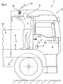
- Fig. 2 an alternative or optionally additional possibility for a comfortable door lock operation by the person 7 is shown on the elevated stand 5.
- the existing operating handle 4 has a complementary arrival and / or shape and / or at least one additional attachment element as a supplementary element, here only by way of example a bracket 13, so that in addition to the usual manual operation and the here (dashed line drawn) foot control with a toe 14 of the tread 6 is easily possible.
- Fig. 3 is another alternative or optionally additional embodiment of an additional door lock operation as a foot control in addition to the operating handle 4 shown.
- a separate maximalbetuschistselement here exemplified as a foot lever 15, provided in the foot of standing on the elevated stand 5 person 7, the pedal 15 here by way of example with the right foot 16 (dashed lines) can be actuated by simply receding.
- the foot lever is in turn preferably mechanically and / or electrically coupled to the operating handle 4 and / or with the opening mechanism of the door lock, as shown schematically by the dashed line 17.
- a hand-operated, portable remote control 18 is provided by the person with 7 on the elevated Stand 5 can be raised.
- the remote control 18 is coupled by means of radio control (represented by the arrows 19, 20) to a radio-actuated opening mechanism for opening the cab door 3.
- radio control represented by the arrows 19, 20
- a radio-actuated opening mechanism for opening the cab door 3 When opening the door lock by means of the remote control 18, the cab door 3 jumps to an opening gap (shown schematically with arrow 19), so that the person 7 behind the cab door 3 can engage and open completely.
Abstract
Die Erfindung betrifft ein Nutzfahrzeug (1), insbesondere ein Baufahrzeug, mit einem Fahrerhaus (2) mit wenigstens einer Fahrerhaustür (3), und mit einem erhöhten Standplatz (5) für eine Person (7), insbesondere auf einem Bauaufstieg oder einer Ladefläche (10) seitlich hinter der wenigstens einen Fahrerhaustür (3), in etwa im Bereich und/oder in der Höhe eines Betätigungsgriffs (4) eines zugeordneten Türschlosses zum Öffnen der Fahrerhaustür (3), vorzugsweise im Griffbereich einer neben dem Fahrzeug (1) auf dem Boden stehenden Person (7'). Erfindungsgemäß ist vorgesehen, dass das Türschloss zum Öffnen der Fahrerhaustür (3) zudem mittels wenigstens eines zusätzlichen Betätigungsmittels (11; 13; 15; 18) betätigbar ist, das zusätzlich zum Betätigungsgriff (4) im Bereich des erhöhten Standplatzes (5) angeordnet oder anordenbar ist. Hierbei ist bevorzugt vorgesehen, dass das zusätzliche Befestigungsmittel (11; 13; 15; 18) beabstandet vom Betätigungsgriff (4) im Bereich des erhöhten Standplatzes (5) angeordnet oder anordenbar ist und/oder als Ergänzungselement am Betätigungsgriff (4) selbst angeordnet oder anordenbar ist.The invention relates to a utility vehicle (1), in particular a construction vehicle, with a driver's cab (2) having at least one driver's door (3), and with an elevated parking space (5) for a person (7), in particular on a construction ladder or a cargo bed ( 10) laterally behind the at least one cab door (3), approximately in the area and / or in the height of an actuating handle (4) of an associated door lock for opening the cab door (3), preferably in the grip area next to the vehicle (1) on the Floor standing person (7 '). According to the invention, the door lock for opening the cab door (3) can also be actuated by means of at least one additional actuating means (11; 13; 15; 18), which can be arranged or arranged in the region of the elevated stand (5) in addition to the actuating handle (4) is. In this case, it is preferably provided that the additional fastening means (11; 13; 15; 18) is arranged or can be arranged at a distance from the actuating handle (4) in the region of the elevated position (5) and / or arranged or can be arranged as a supplementary element on the actuating handle (4) is.
Description
Die Erfindung betrifft ein Nutzfahrzeug, insbesondere ein Baufahrzeug, mit einem Fahrerhaus mit wenigstens einer Fahrerhaustür nach dem Oberbegriff des Anspruchs 1.The invention relates to a utility vehicle, in particular a construction vehicle, with a driver's cab having at least one driver's door according to the preamble of
Es sind Nutzfahrzeuge, insbesondere Baufahrzeuge, allgemein bekannt, mit einem erhöhten Stehplatz für eine Person, insbesondere auf einem sogenannten Bauaufstieg oder einer Ladefläche seitlich hinter der wenigstens einen Fahrerhaustür, etwa in der Höhe eines Betätigungsgriffs eines Türschlosses der Fahrerhaustür. Ein solcher Betätigungsgriff dient zum Öffnen der Fahrerhaustür und liegt üblicherweise in einem oberen Griffbereich einer neben dem Fahrzeug auf dem Boden stehenden Person.There are commercial vehicles, especially construction vehicles, generally known, with an increased standing room for a person, especially on a so-called construction climb or a loading area laterally behind the at least one cab door, approximately at the height of an operating handle of a door lock the cab door. Such an actuating handle is used to open the cab door and is usually located in an upper grip area of a person standing next to the vehicle on the floor.
Eine Person, insbesondere ein Fahrer kann von einem solchen erhöhten Stehplatz aus, bei stehendem Fahrzeug den Bereich im Umfeld des Fahrzeugs wesentlich besser einsehen und beobachten als eine Person, die neben dem Fahrzeug auf dem Boden steht. Insbesondere kann beispielsweise ein Beladevorgang gut kontrolliert und es können beispielsweise Beladehilfen bei gutem Sichtkontakt ferngesteuert bedient werden. Ein solcher erhöhter Stehplatz kann einfach auf einer Ladefläche hinter einem Fahrerhaus im Bereich einer Fahrerhaustür eingenommen werden. Bei allgemein bekannten Nutzfahrzeugen, insbesondere bei Baufahrzeugen wird ein solcher erhöhter Stehplatz auch dadurch zur Verfügung gestellt, dass ein sogenannter Bauaufstieg, insbesondere über einem vorderen Radhaus als Trittfläche angebracht ist, gegebenenfalls in Verbindung mit einer Halteeinrichtung für die Hände im Dachbereich des Fahrerhaus.A person, in particular a driver can view and observe the area around the vehicle substantially better than a person standing on the ground next to the vehicle from such an elevated standing position. In particular, for example, a loading process is well controlled and it can, for example Beladehilfen be operated remotely controlled with good visual contact. Such elevated standing space can easily be taken on a loading area behind a driver's cab near a cab door. In well-known commercial vehicles, especially in construction vehicles, such an increased standing space is also provided by the fact that a so-called construction ascent, in particular mounted on a front wheel arch as a tread, optionally in conjunction with a holding device for the hands in the roof area of the cab.
Um auf die Trittfläche eines Bauaufstiegs zu gelangen, muss eine Person bei offener Fahrerhaustür über das Fahrerhaus auf die Trittfläche hinaufsteigen. Auch der Aufstieg auf eine Ladefläche kann so erfolgen. Der Abstieg von der Trittfläche des Bauaufstiegs oder der Ladefläche erfolgt dann ebenfalls über das Fahrerhaus bei offener Fahrerhaustür. Falls die Fahrerhaustür, während sich die Person auf der Trittfläche des Bauaufstiegs/Ladefläche befindet, geschlossen worden ist, kann der relativ weit unten im Fußbereich der Person liegende Betätigungsgriff des Türschlosses nicht oder nur sehr mühsam betätigt werden, so dass die Person meist kräftezehrend und sicherheitskritisch ohne Einstiegsmöglichkeit ins Fahrerhaus von der Trittfläche nach unten zum Boden turnen muss. Deshalb wird üblicherweise die Fahrerhaustür von einer Person auf den Bauaufstieg zum Beispiel bei einer Überwachung von Beladevorgängen offengelassen. Damit sind während dieser Zeit der Innenraum des Fahrerhauses und die Türbedienmodule widrigen Umwelteinflüssen ungeschützt ausgesetzt. Insbesondere kühlt bei tiefen Außentemperatur das innere des Fahrerhauses bei offener Fahrerhaustür nachteilig ab und muss bei einer Weiterfahrt erst wieder energieverzehrend aufgewärmt werden.In order to get on the tread of a construction climb, a person with open cab door must climb above the cab on the tread. The ascent to a loading area can also be done this way. The descent from the tread of the construction ascent or the loading area is then also about the cab with the cab door open. If the cab door, while the person is on the tread surface of the construction / loading area, has been closed, the lying relatively low down in the foot of the person operating handle of the door lock can not or only very laboriously be operated, so that the person usually debilitating and safety-critical without entry into the cab from the tread down to the floor gymnastics must. Therefore, usually the Cab door left open by a person on the construction ascent, for example, in a monitoring of loading operations. Thus, the interior of the cab and the door operating modules are exposed to adverse environmental conditions unprotected during this time. In particular, when the outside temperature is low, the interior of the driver's cab cools down adversely when the driver's cab door is open and must first be reheated to save energy when driving on.
Aufgabe der Erfindung ist es daher, ein Nutzfahrzeug, insbesondere ein Baufahrzeug, mit einem Fahrerhaus und mit wenigstens einer Fahrerhaustür so auszurüsten, dass eine Person bequem einen Abstieg von einem Bauaufstieg/Ladefläche auch nach einer Tätigkeit bei geschlossener Fahrerhaustür mit geschlossenem Türschloss bequem durchführen kann.The object of the invention is therefore to equip a commercial vehicle, in particular a construction vehicle, with a cab and with at least one cab door so that a person can easily perform a descent from a construction ramp / loading area even after an activity with the cab door closed with a closed door lock.
Diese Aufgabe wird durch die Merkmale der unabhängigen Patentansprüche gelöst. Bevorzugte Weiterbildungen sind in den Unteransprüchen offenbart.This object is solved by the features of the independent claims. Preferred developments are disclosed in the subclaims.
Gemäß Patentanspruch 1 wird ein Nutzfahrzeug, insbesondere ein Baufahrzeug, vorgeschlagen, mit einem Fahrerhaus mit wenigstens einer Fahrerhaustür, und mit einem erhöhten Stand- bzw. Stehplatz für eine Person, insbesondere auf einem Bauaufstieg oder einer in etwa Ladefläche seitlich hinter der wenigstens einen Fahrerhaustür, in etwa im Bereich und/oder in der Höhe eines Betätigungsgriffs eines zugeordneten Türschlosses zum Öffnen der Fahrerhaustür im Griffbereich einer neben dem Fahrzeug auf dem Boden stehenden Person. Erfindungsgemäß ist vorgesehen, das Türschloss zum Öffnen der Fahrerhaustür zudem mittels wenigstens eines zusätzlichen Betätigungsmittels betätigbar ist, das zusätzlich zum Betätigungsgriff im Bereich des erhöhten Standplatzes angeordnet oder anordenbar ist. Dies kann gemäß einer bevorzugten Ausführungsform konkret zum Beispiel so erfolgen, dass das zusätzliche Befestigungsmittel beabstandet vom Betätigungsgriff im Bereich des erhöhten Standplatzes angeordnet oder anordenbar ist. Des Weiteren kann dies alternativ oder zusätzlich zum Beispiel dadurch erfolgen, dass das zusätzliche Befestigungsmittel als Ergänzungselement am Betätigungsgriff selbst angeordnet oder anordenbar ist. Mit der erfindungsgemäßen Lösung kann das Türschloss zum Öffnen der Fahrerhaustür somit von einer Person am erhöhten Standplatz mittels wenigstens eines von dort von der Person gut erreichbaren Betätigungsmittels betätigt werden.According to
Damit wird erreicht, dass eine Person zum Verlassen des erhöhten Standplatzes bei vorher geschlossener Fahrerhaustür einen kräftezehrenden Abstieg mit nicht immer vorhandenem turnerischen Geschick durchführen muss oder versuchen muss, durch Verrenkungen gegebenenfalls den üblichen (unteren) Betätigungsgriff des Türschlosses für eine Handbetätigung zum Öffnen der Fahrerhaustür zu erreichen.This ensures that a person to leave the elevated stand with previously closed cab door has to perform an exhausting descent with not always present turneric skill or must try, by dislocations if necessary the usual (lower) operating handle of the door lock for a manual operation to open the cab door to achieve.
Da die Person auf dem erhöhten Standplatz erfindungsgemäß einfach und bequem das Türschloss der Fahrerhaustür zum Öffnen betätigen und einfach absteigen kann, ist es vorteilhaft möglich, während der Verweildauer auf dem erhöhten Standplatz die Fahrerhaustür zum Schutz des Fahrerhausinnenraums und der Türbedienmodule vor Umwelteinflüssen zu schließen, wobei insbesondere das Innere des Fahrerhauses durch die kürzeren Öffnungszeiten der Fahrerhaustür wärmer bleibt.Since the person on the elevated stand according to the invention can easily and conveniently operate the door lock of the cab door to open and dismount, it is advantageously possible to close during the dwell time on the elevated stand the cab door to protect the cab interior and the door control modules from environmental influences In particular, the interior of the cab by the shorter opening times of the cab door remains warmer.
In einer konkreten Ausführungsform wird vorgeschlagen, dass dazu als Betätigungsmittel zusätzlich zu einem dem Türschloss zugeordneten unteren Betätigungsgriff wenigstens ein weiterer, in Hochachsenrichtung gesehen oberer Betätigungsgriff angeordnet wird, und zwar insbesondere im oberen, seitlich hinteren Bereich der Fahrerhaustür und/oder im hinteren oberen Bereich des Fahrerhauses und damit im bequemen Griffbereich einer Person auf dem erhöhten Standplatz angeordnet wird. Ein solcher zusätzlicher oberer Betätigungsgriff soll in einer funktionsfähigen, kostengünstigen Konstruktion mit dem unteren Betätigungsgriff und/oder mit dem Öffnungsmechanismus des Türschlosses, vorzugsweise mechanisch und/oder elektrisch, für eine Türöffnung gekoppelt sein. Eine Person kann mit dem oberen Betätigungsgriff auch am erhöhten Standplatz bei Bedarf eine Fahrerhaustür bequem öffnen.In a specific embodiment, it is proposed that, in addition to a lower operating handle associated with the door lock, at least one further upper operating handle, seen in the vertical axis direction, is arranged for this purpose, in particular in the upper, laterally rear region of the cab door and / or in the rear upper region of the door Cab and thus in the comfortable grip area of a person is placed on the elevated stand. Such an additional upper operating handle should be coupled in a functional, cost-effective construction with the lower actuating handle and / or with the opening mechanism of the door lock, preferably mechanically and / or electrically, for a door opening. A person can easily open a cab door with the upper operating handle, even at the elevated stand if necessary.
Eine mechanische Kopplung kann dabei zum Beispiel mit Gestängen und/oder Seilzügen und/oder hydraulisch und/oder pneumatisch erfolgen. Eine elektrische Kopplung kann zum Beispiel mittels ansteuerbarer Elektromagnete und/oder mittels elektromotorischer Aktuatoren erfolgen.A mechanical coupling can be done, for example, with poles and / or cables and / or hydraulically and / or pneumatically. An electrical coupling can be done for example by means of controllable electromagnets and / or by means of electromotive actuators.
In einer alternativen oder gegebenenfalls zusätzlichen Ausführungsform kann als Betätigungsmittel eine handbetätigbare Fernbedienung vorgesehen sein, die am erhöhten Standplatz von einer Person bedienbar und die mittels Funksteuerung mit einem für eine Funkbetätigung ausgerüsteten Öffnungsmechanismus zum Öffnen der Fahrerhaustür gekoppelt ist. Mit der bisher üblichen Fernbedienungsfunktion kann bei einer Fahrzeugtür lediglich der Sperrmechanismus entriegelt werden - die Fahrzeugtür bleibt dabei aber nach wie vor geschlossen und muss anschließend mit dem Betätigungsgriff von Hand geöffnet werden. Erfindungsgemäß soll mit der hier beanspruchten Fernbedienung nicht (nur) der Sperrmechanismus entriegelt werden, sondern insgesamt das Türschloss dergestalt, dass die Fahrerhaustür zumindest um einen Öffnungsspalt aufspringt, so dass die Person auf dem erhöhten Standplatz die Fahrerhaustür ergreifen und insgesamt öffnen kann. Alternativ kann auch die Fahrertür mittels der Fernbedienung unter Verwendung eines Öffnungsaktuators selbsttätig geöffnet werden. Eine solche Fernbedienung kann entweder als tragbares und damit im Bereich des erhöhten Standplatzes anordenbares Gerät ausgebildet sein, das von einer Person auf den erhöhten Standplatz mitgenommen werden kann, oder dort ortsfest im Griffbereich am erhöhten Standplatz angeordnet sein. Die erfindungsgemäße Fernbedienungsfunktion kann dabei als Zusatzfunktion in an sich bekannte Fernbedienungen, wie beispielsweise in eine Formbedienung zur Steuerung von Beladevorgängen, integriert werden.In an alternative or possibly additional embodiment may be provided as actuating means a hand-operated remote control, which is operated at the elevated stand by a person and is coupled by means of radio control with an equipped for a radio control opening mechanism for opening the cab door. With the usual remote control function only the locking mechanism can be unlocked in a vehicle door - the vehicle door remains but still closed and must then be opened with the operating handle by hand. According to the invention, the (not only) the locking mechanism is to be unlocked with the remote control claimed here, but a total of the door lock in such a way that the cab door jumps at least an opening gap, so that the person on the elevated Stand can grab the cab door and open in total. Alternatively, the driver's door can also be opened automatically by means of the remote control using an opening actuator. Such a remote control can be designed either as a portable and thus can be arranged in the region of the elevated stand device that can be taken by a person on the elevated stand, or be there fixed in the grip area on elevated stand. The remote control function according to the invention can be integrated as an additional function in known remote controls, such as in a mold control for controlling loading operations.
In einer alternativen oder gegebenenfalls zusätzlichen Ausführungsform kann als Betätigungsmittel, das mit dem Betätigungsgriff (im Falle von einem oberen und einem unteren Betätigungsgriff ist das bevorzugt der untere Betätigungsgriff) und/oder mit dem Öffnungsmechanismus des Türschlosses gekoppelt ist, wenigstens ein Fußbetätigungselement im Fußbereich einer Person auf dem erhöhten Standplatz vorgesehen sein. Ein solches zusätzliches Fußbetätigungselement kann dazu zum Beispiel etwa in der Höhe des Betätigungsgriffs (im Falle von einem oberen und einem unteren Betätigungsgriff ist das bevorzugt der untere Betätigungsgriff) angeordnet werden. Als Fußbetätigungselement können bekannte Bauteile, wie ein Fußhebel und/oder ein Fußschalter vorgesehen sein, mit denen der Öffnungsmechanismus des Türschlosses, vorzugsweise mechanisch und/oder elektrisch, wie bereits oben beschrieben, gekoppelt werden kann.In an alternative or possibly additional embodiment, as an actuating means which is coupled to the actuating handle (in the case of an upper and a lower actuating handle which is preferably the lower actuating handle) and / or with the opening mechanism of the door lock, at least one foot actuating element in the foot area of a person be provided on the elevated stand. For example, such an additional foot actuating element can be arranged approximately at the height of the actuating handle (in the case of an upper and a lower actuating handle, this is preferably the lower actuating handle). As a foot control element known components, such as a pedal and / or a foot switch may be provided with which the opening mechanism of the door lock, preferably mechanically and / or electrically, as already described above, can be coupled.
Mit einem solchen Fußbetätigungselement kann eine Person auf dem erhöhten Standplatz bequem und ohne sicherheitskritische Verrenkungen oder turnerische Auf- und Absteigtätigkeiten die Fahrerhaustür öffnen.With such a foot control element, a person can open the cab door comfortably on the elevated stand comfortably and without safety-critical dislocations or gymnastic up and down activities.
In einer weiteren, alternativen oder gegebenenfalls zusätzlichen Ausführung wird der Umstand benutzt, dass der Betätigungsgriff (im Falle von einem oberen und einem unteren Betätigungsgriff ist das bevorzugt der untere Betätigungsgriff) üblicherweise etwa im Fußbereich einer Person auf dem erhöhten Standplatz liegt. Dieser Betätigungsgriff kann dann zur Ausbildung des zusätzlichen Betätigungsmittels wenigstens eine zusätzliche Ausformung und/oder Anformung und/oder wenigstens ein zusätzliches Anbauelement aufweisen, wodurch der Betätigungsgriff so mit wenigstens einem Ergänzungselement, insbesondere einem Bügel und/oder einer Schlaufe, ergänzt ist, dass mittels dieses Ergänzungselementes zusätzlich zu einer Handbedienung auch eine Fußbetätigung, zum Beispiel mit einer Fußspitze, vom erhöhten Standplatz aus durchführbar ist.In a further, alternative or optionally additional embodiment, the fact is used that the operating handle (in the case of an upper and a lower operating handle, preferably the lower operating handle) is usually located approximately in the foot area of a person on the elevated stand. This actuating handle may then have at least one additional molding and / or molding and / or at least one additional attachment for forming the additional actuating means, whereby the actuating handle is supplemented with at least one supplementary element, in particular a bracket and / or a loop, that by means of this Supplementary element in addition to a manual operation and a foot operation, for example, with a toe, from the elevated stand is feasible.
Anhand einer Zeichnung wird die Erfindung weiter beispielhaft erläutert.Reference to a drawing, the invention is further exemplified.
Es zeigen:
- Fig. 1
- eine schematische Seitenansicht im Bereich eines Fahrerhauses eines Lastkraftwagens mit einer ersten Ausführungsform einer zusätzlichen Türschlossbetätigung,
- Fig. 2
- eine Ansicht entsprechend
Fig. 1 mit einer zweiten Ausführungsform einer zusätzlichen Türschlossbetätigung, - Fig. 3
- eine Ansicht entsprechend
Fig. 1 mit einer dritten Ausführungsform einer zusätzlichen Türschlossbetätigung, und - Fig. 4
- eine Ansicht entsprechend
Fig. 1 mit einer vierten Ausführungsform einer zusätzlichen Türschlossbetätigung.
- Fig. 1
- 1 a schematic side view in the region of a driver's cab of a truck with a first embodiment of an additional door lock actuation,
- Fig. 2
- a view accordingly
Fig. 1 with a second embodiment of an additional door lock actuation, - Fig. 3
- a view accordingly
Fig. 1 with a third embodiment of an additional door lock actuation, and - Fig. 4
- a view accordingly
Fig. 1 with a fourth embodiment of an additional door lock operation.
In
Der untere Betätigungsgriff 4 liegt hier bequem im oberen Griffbereich einer neben dem Nutzfahrzeug 1 stehenden (strichliert eingezeichneten) Person 7'.The
Das hier dargestellte Fahrerhaus 2 ist mit einem sogenannten Bauaufstieg als erhöhtem Standplatz 5 mit einer Trittfläche 6 für eine erhöht stehende Person 7 sowie bevorzugt auch mit einer Haltestange 8 im Dachbereich des Fahrerhauses 2 ausgerüstet. Die Trittfläche 6 des erhöhten Standplatzes 5 ist oberhalb eines vorderen Radhauses 9 seitlich hinter der Fahrerhaustür 3, etwa in Höhe des unteren Betätigungsgriffs 4 angeordnet. Von diesem erhöhten Standplatz 5 hat die Person 7 einen guten Überblick, insbesondere auf den Bereich einer Ladefläche 10, um beispielsweise einen Beladevorgang zu kontrollieren und zu steuern.The
In der dargestellten Ausführungsform des Fahrerhauses 2 ist dieses nach hinten über die Fahrerhaustür 3 hinaus verlängert und der Standplatz 5 mit der Trittfläche 6 liegt in diesem Verlängerungsbereich. Alternativ könnte die Ladefläche 10 auch bei einem kürzeren Fahrerhause 2 bis unmittelbar hinter die Fahrerhaustür 3 herangeführt sein (strichlierte Linie 22), so dass dann alternativ die Person 7 auf der Ladefläche 10 als erhöhtem Standplatz stehen könnte.In the illustrated embodiment of the
Sowohl vom Bauaufstieg als erhöhtem Standplatz als auch gegebenenfalls von einem erhöhten Standplatz auf einer Ladefläche 10 soll die Person 7 bequem eine geschlossene Fahrerhaustür 3 öffnen können.Both the construction as an elevated stand and possibly from an elevated stand on a
In der konkreten Ausführungsform nach
In
In
In
Bei jeder der in den
- 11
- Nutzfahrzeugcommercial vehicle
- 22
- Fahrerhausdriver's cab
- 33
- FahrerhaustürCab door
- 44
- unterer Betätigungsgrifflower operating handle
- 55
- Standplatz/BauaufstiegStand / Construction-site
- 66
- Trittflächetread
- 77
- Personperson
- 7'7 '
- Personperson
- 88th
- HaltestangeHandrail
- 99
- Radhauswheelhouse
- 1010
- Ladeflächeload area
- 1111
- oberer Betätigungsgriffupper operating handle
- 1212
- Linieline
- 1313
- Bügelhanger
- 1414
- Fußspitzetoe
- 1515
- Fußhebeltreadle
- 1616
- rechter Fußright foot
- 1717
- Linieline
- 1818
- Fernbedienungremote control
- 1919
- Pfeilarrow
- 2020
- Pfeilarrow
- 2121
- Pfeilarrow
- 2222
- Linieline
Claims (8)
mit einem erhöhten Standplatz (5) für eine Person (7), insbesondere auf einem Bauaufstieg oder einer Ladefläche seitlich hinter der wenigstens einen Fahrerhaustür (3), in etwa im Bereich und/oder in etwa in der Höhe eines Betätigungsgriffs (4) eines zugeordneten Türschlosses zum Öffnen der Fahrerhaustür (3), vorzugsweise im Griffbereich einer neben dem Fahrzeug (1) auf dem Boden stehenden Person (7'),
dadurch gekennzeichnet,
dass das Türschloss zum Öffnen der Fahrerhaustür (3) zudem mittels wenigstens eines zusätzlichen Betätigungsmittels (11; 13; 15; 18) betätigbar ist, das zusätzlich zum Betätigungsgriff (4) im Bereich des erhöhten Standplatzes (5) angeordnet oder anordenbar ist, wobei bevorzugt vorgesehen ist, dass das zusätzliche Befestigungsmittel (11; 13; 15; 18) beabstandet vom Betätigungsgriff (4) im Bereich des erhöhten Standplatzes (5) angeordnet oder anordenbar ist und/oder als Ergänzungselement am Betätigungsgriff (4) selbst angeordnet oder anordenbar ist.Commercial vehicle (1), in particular construction vehicle, with a driver's cab (2) with at least one driver's door (3), and
with an elevated stand (5) for a person (7), in particular on a construction ramp or a loading area laterally behind the at least one cab door (3), approximately in the area and / or approximately in the height of an operating handle (4) of an associated Door lock for opening the cab door (3), preferably in the grip area of a person (7 ') standing on the ground next to the vehicle (1),
characterized,
in that the door lock for opening the cab door (3) can also be actuated by means of at least one additional actuating means (11; 13; 15; 18) which is arranged or can be arranged in the region of the raised stand (5) in addition to the actuating handle (4) it is provided that the additional fastening means (11; 13; 15; 18) is arranged or can be arranged at a distance from the actuating handle (4) in the region of the elevated position (5) and / or is itself arranged or can be arranged as a supplementary element on the actuating handle (4).
dass eine mechanische Kopplung mittels Gestängen und/oder Seilzügen und/oder hydraulisch und/oder pneumatisch vorgesehen ist, und/oder
dass eine elektrische Kopplung, vorzugsweise mittels wenigstens eines ansteuerbaren Elektromagneten und/oder mittels wenigstens eines elektromotorischen Aktuators, vorgesehen ist.Commercial vehicle according to claim 2, characterized in that
that a mechanical coupling is provided by means of rods and / or cables and / or hydraulically and / or pneumatically, and / or
in that an electrical coupling, preferably by means of at least one controllable electromagnet and / or by means of at least one electromotive actuator, is provided.
Applications Claiming Priority (1)
| Application Number | Priority Date | Filing Date | Title |
|---|---|---|---|
| DE102016004586.8A DE102016004586A1 (en) | 2016-04-14 | 2016-04-14 | Commercial vehicle, in particular construction vehicle, with a cab with at least one cab door |
Publications (2)
| Publication Number | Publication Date |
|---|---|
| EP3231971A1 true EP3231971A1 (en) | 2017-10-18 |
| EP3231971B1 EP3231971B1 (en) | 2020-09-02 |
Family
ID=58536707
Family Applications (1)
| Application Number | Title | Priority Date | Filing Date |
|---|---|---|---|
| EP17000598.7A Active EP3231971B1 (en) | 2016-04-14 | 2017-04-07 | Commercial vehicle, in particular construction vehicle, with a driver's cab with at least one cab door |
Country Status (2)
| Country | Link |
|---|---|
| EP (1) | EP3231971B1 (en) |
| DE (1) | DE102016004586A1 (en) |
Citations (5)
| Publication number | Priority date | Publication date | Assignee | Title |
|---|---|---|---|---|
| JPH02117909U (en) * | 1989-03-10 | 1990-09-21 | ||
| EP1270853A2 (en) * | 2001-06-16 | 2003-01-02 | ArvinMeritor Light Vehicle Systems (UK) Ltd | Vehicle access and engagement means |
| DE102010005261A1 (en) * | 2010-01-20 | 2011-07-21 | Carl Wilhelm Cleff GmbH & Co KG, 42277 | Door lock for rail vehicle e.g. train, has blocking device controlling displacement of closure element by lock bolt, which comprises retaining surface contacting with counter retaining surface of blocking device |
| KR101563983B1 (en) * | 2014-07-22 | 2015-10-28 | 임국건 | Door opening and closing device of working vehicle |
| EP3006655A1 (en) * | 2014-10-09 | 2016-04-13 | Manitou Italia S.r.l. | An assisted movement device for a door of a vehicle |
-
2016
- 2016-04-14 DE DE102016004586.8A patent/DE102016004586A1/en not_active Withdrawn
-
2017
- 2017-04-07 EP EP17000598.7A patent/EP3231971B1/en active Active
Patent Citations (5)
| Publication number | Priority date | Publication date | Assignee | Title |
|---|---|---|---|---|
| JPH02117909U (en) * | 1989-03-10 | 1990-09-21 | ||
| EP1270853A2 (en) * | 2001-06-16 | 2003-01-02 | ArvinMeritor Light Vehicle Systems (UK) Ltd | Vehicle access and engagement means |
| DE102010005261A1 (en) * | 2010-01-20 | 2011-07-21 | Carl Wilhelm Cleff GmbH & Co KG, 42277 | Door lock for rail vehicle e.g. train, has blocking device controlling displacement of closure element by lock bolt, which comprises retaining surface contacting with counter retaining surface of blocking device |
| KR101563983B1 (en) * | 2014-07-22 | 2015-10-28 | 임국건 | Door opening and closing device of working vehicle |
| EP3006655A1 (en) * | 2014-10-09 | 2016-04-13 | Manitou Italia S.r.l. | An assisted movement device for a door of a vehicle |
Also Published As
| Publication number | Publication date |
|---|---|
| DE102016004586A1 (en) | 2017-10-19 |
| DE102016004586A8 (en) | 2017-12-14 |
| EP3231971B1 (en) | 2020-09-02 |
Similar Documents
| Publication | Publication Date | Title |
|---|---|---|
| EP3194696B1 (en) | Flush comfort handle | |
| EP3412830B1 (en) | Construction machine with operator stand and access protection | |
| WO2018145901A1 (en) | Motor vehicle | |
| EP2760688A1 (en) | Motor vehicle liftgate | |
| DE102017206728A1 (en) | Method for lowering a window of a vehicle door and designed for carrying out the method trained vehicle | |
| DE602004010564T2 (en) | Rear bumper structure for a vehicle and vehicle provided with the like | |
| DE102015214086B4 (en) | Door system for a passenger car with at least two rows of seats | |
| DE4128460A1 (en) | ROOF ARRANGEMENT FOR A MOTOR VEHICLE | |
| DE102006043817A1 (en) | Movement mechanism for storage compartment flap for closing opening in vehicle wall of omnibus, has lifting kinematics, and storage compartment flap is automatically transferred between closing and opening position by drive device | |
| EP3341673B1 (en) | Lifting/pivoting device for a manhole cover of a protected vehicle, manhole cover arrangement and protected vehicle | |
| EP3231971A1 (en) | Commercial vehicle, in particular construction vehicle, with a driver's cab with at least one cab door | |
| DE102014212988A1 (en) | Vehicle with a boarding device | |
| DE102014014085A1 (en) | Motor vehicle, comprising a front flap which is pivotally mounted on two hinges on a body | |
| DE102013012604A1 (en) | Vehicle with a rear seat arrangement | |
| EP3246503B1 (en) | Method for lowering a window pane of a vehicle door and vehicle designed to carry out the method | |
| EP3170721B1 (en) | Roof arch structure, structure for commercial vehicles, swap bridges, and commercial vehicle with body | |
| DE202011105309U1 (en) | Cabinless self-propelled construction machine, in particular road milling machine | |
| EP2017128A1 (en) | Driver's cab of a vehicle | |
| DE102012104987B4 (en) | Outside door for the driver's cab of rail vehicles | |
| EP2653143B1 (en) | Coach with a lifting device as an aid to entry for a wheelchair user | |
| EP2889446A1 (en) | Tailgate of a vehicle, grip module for such a tailgate and corresponding vehicle | |
| DE102010015480B4 (en) | Method for operating a construction hoist | |
| EP3319856B1 (en) | Chair for a chairlift | |
| DE2318614C3 (en) | Entry paneling on weather canopies and cabs of commercial vehicles | |
| DE19712406B4 (en) | Device for controlling the movement of a lifting unit, such as an aerial ladder |
Legal Events
| Date | Code | Title | Description |
|---|---|---|---|
| PUAI | Public reference made under article 153(3) epc to a published international application that has entered the european phase |
Free format text: ORIGINAL CODE: 0009012 |
|
| STAA | Information on the status of an ep patent application or granted ep patent |
Free format text: STATUS: THE APPLICATION HAS BEEN PUBLISHED |
|
| AK | Designated contracting states |
Kind code of ref document: A1 Designated state(s): AL AT BE BG CH CY CZ DE DK EE ES FI FR GB GR HR HU IE IS IT LI LT LU LV MC MK MT NL NO PL PT RO RS SE SI SK SM TR |
|
| AX | Request for extension of the european patent |
Extension state: BA ME |
|
| STAA | Information on the status of an ep patent application or granted ep patent |
Free format text: STATUS: REQUEST FOR EXAMINATION WAS MADE |
|
| 17P | Request for examination filed |
Effective date: 20180418 |
|
| RBV | Designated contracting states (corrected) |
Designated state(s): AL AT BE BG CH CY CZ DE DK EE ES FI FR GB GR HR HU IE IS IT LI LT LU LV MC MK MT NL NO PL PT RO RS SE SI SK SM TR |
|
| STAA | Information on the status of an ep patent application or granted ep patent |
Free format text: STATUS: EXAMINATION IS IN PROGRESS |
|
| 17Q | First examination report despatched |
Effective date: 20180903 |
|
| RAP1 | Party data changed (applicant data changed or rights of an application transferred) |
Owner name: MAN TRUCK & BUS SE |
|
| GRAP | Despatch of communication of intention to grant a patent |
Free format text: ORIGINAL CODE: EPIDOSNIGR1 |
|
| STAA | Information on the status of an ep patent application or granted ep patent |
Free format text: STATUS: GRANT OF PATENT IS INTENDED |
|
| RIC1 | Information provided on ipc code assigned before grant |
Ipc: E05B 51/02 20060101ALN20200227BHEP Ipc: E05B 83/42 20140101AFI20200227BHEP Ipc: E05B 53/00 20060101ALN20200227BHEP Ipc: E05B 85/10 20140101ALN20200227BHEP |
|
| INTG | Intention to grant announced |
Effective date: 20200324 |
|
| GRAS | Grant fee paid |
Free format text: ORIGINAL CODE: EPIDOSNIGR3 |
|
| GRAA | (expected) grant |
Free format text: ORIGINAL CODE: 0009210 |
|
| STAA | Information on the status of an ep patent application or granted ep patent |
Free format text: STATUS: THE PATENT HAS BEEN GRANTED |
|
| AK | Designated contracting states |
Kind code of ref document: B1 Designated state(s): AL AT BE BG CH CY CZ DE DK EE ES FI FR GB GR HR HU IE IS IT LI LT LU LV MC MK MT NL NO PL PT RO RS SE SI SK SM TR |
|
| REG | Reference to a national code |
Ref country code: GB Ref legal event code: FG4D Free format text: NOT ENGLISH |
|
| REG | Reference to a national code |
Ref country code: AT Ref legal event code: REF Ref document number: 1308978 Country of ref document: AT Kind code of ref document: T Effective date: 20200915 Ref country code: CH Ref legal event code: EP |
|
| REG | Reference to a national code |
Ref country code: DE Ref legal event code: R096 Ref document number: 502017006981 Country of ref document: DE |
|
| REG | Reference to a national code |
Ref country code: IE Ref legal event code: FG4D Free format text: LANGUAGE OF EP DOCUMENT: GERMAN |
|
| REG | Reference to a national code |
Ref country code: NL Ref legal event code: FP |
|
| REG | Reference to a national code |
Ref country code: SE Ref legal event code: TRGR |
|
| REG | Reference to a national code |
Ref country code: LT Ref legal event code: MG4D |
|
| PG25 | Lapsed in a contracting state [announced via postgrant information from national office to epo] |
Ref country code: FI Free format text: LAPSE BECAUSE OF FAILURE TO SUBMIT A TRANSLATION OF THE DESCRIPTION OR TO PAY THE FEE WITHIN THE PRESCRIBED TIME-LIMIT Effective date: 20200902 Ref country code: LT Free format text: LAPSE BECAUSE OF FAILURE TO SUBMIT A TRANSLATION OF THE DESCRIPTION OR TO PAY THE FEE WITHIN THE PRESCRIBED TIME-LIMIT Effective date: 20200902 Ref country code: HR Free format text: LAPSE BECAUSE OF FAILURE TO SUBMIT A TRANSLATION OF THE DESCRIPTION OR TO PAY THE FEE WITHIN THE PRESCRIBED TIME-LIMIT Effective date: 20200902 Ref country code: NO Free format text: LAPSE BECAUSE OF FAILURE TO SUBMIT A TRANSLATION OF THE DESCRIPTION OR TO PAY THE FEE WITHIN THE PRESCRIBED TIME-LIMIT Effective date: 20201202 Ref country code: BG Free format text: LAPSE BECAUSE OF FAILURE TO SUBMIT A TRANSLATION OF THE DESCRIPTION OR TO PAY THE FEE WITHIN THE PRESCRIBED TIME-LIMIT Effective date: 20201202 Ref country code: GR Free format text: LAPSE BECAUSE OF FAILURE TO SUBMIT A TRANSLATION OF THE DESCRIPTION OR TO PAY THE FEE WITHIN THE PRESCRIBED TIME-LIMIT Effective date: 20201203 |
|
| PG25 | Lapsed in a contracting state [announced via postgrant information from national office to epo] |
Ref country code: PL Free format text: LAPSE BECAUSE OF FAILURE TO SUBMIT A TRANSLATION OF THE DESCRIPTION OR TO PAY THE FEE WITHIN THE PRESCRIBED TIME-LIMIT Effective date: 20200902 Ref country code: RS Free format text: LAPSE BECAUSE OF FAILURE TO SUBMIT A TRANSLATION OF THE DESCRIPTION OR TO PAY THE FEE WITHIN THE PRESCRIBED TIME-LIMIT Effective date: 20200902 Ref country code: LV Free format text: LAPSE BECAUSE OF FAILURE TO SUBMIT A TRANSLATION OF THE DESCRIPTION OR TO PAY THE FEE WITHIN THE PRESCRIBED TIME-LIMIT Effective date: 20200902 |
|
| PG25 | Lapsed in a contracting state [announced via postgrant information from national office to epo] |
Ref country code: CZ Free format text: LAPSE BECAUSE OF FAILURE TO SUBMIT A TRANSLATION OF THE DESCRIPTION OR TO PAY THE FEE WITHIN THE PRESCRIBED TIME-LIMIT Effective date: 20200902 Ref country code: RO Free format text: LAPSE BECAUSE OF FAILURE TO SUBMIT A TRANSLATION OF THE DESCRIPTION OR TO PAY THE FEE WITHIN THE PRESCRIBED TIME-LIMIT Effective date: 20200902 Ref country code: PT Free format text: LAPSE BECAUSE OF FAILURE TO SUBMIT A TRANSLATION OF THE DESCRIPTION OR TO PAY THE FEE WITHIN THE PRESCRIBED TIME-LIMIT Effective date: 20210104 Ref country code: EE Free format text: LAPSE BECAUSE OF FAILURE TO SUBMIT A TRANSLATION OF THE DESCRIPTION OR TO PAY THE FEE WITHIN THE PRESCRIBED TIME-LIMIT Effective date: 20200902 Ref country code: SM Free format text: LAPSE BECAUSE OF FAILURE TO SUBMIT A TRANSLATION OF THE DESCRIPTION OR TO PAY THE FEE WITHIN THE PRESCRIBED TIME-LIMIT Effective date: 20200902 |
|
| PG25 | Lapsed in a contracting state [announced via postgrant information from national office to epo] |
Ref country code: IS Free format text: LAPSE BECAUSE OF FAILURE TO SUBMIT A TRANSLATION OF THE DESCRIPTION OR TO PAY THE FEE WITHIN THE PRESCRIBED TIME-LIMIT Effective date: 20210102 Ref country code: ES Free format text: LAPSE BECAUSE OF FAILURE TO SUBMIT A TRANSLATION OF THE DESCRIPTION OR TO PAY THE FEE WITHIN THE PRESCRIBED TIME-LIMIT Effective date: 20200902 Ref country code: AL Free format text: LAPSE BECAUSE OF FAILURE TO SUBMIT A TRANSLATION OF THE DESCRIPTION OR TO PAY THE FEE WITHIN THE PRESCRIBED TIME-LIMIT Effective date: 20200902 |
|
| REG | Reference to a national code |
Ref country code: DE Ref legal event code: R097 Ref document number: 502017006981 Country of ref document: DE |
|
| PG25 | Lapsed in a contracting state [announced via postgrant information from national office to epo] |
Ref country code: SK Free format text: LAPSE BECAUSE OF FAILURE TO SUBMIT A TRANSLATION OF THE DESCRIPTION OR TO PAY THE FEE WITHIN THE PRESCRIBED TIME-LIMIT Effective date: 20200902 |
|
| PLBE | No opposition filed within time limit |
Free format text: ORIGINAL CODE: 0009261 |
|
| STAA | Information on the status of an ep patent application or granted ep patent |
Free format text: STATUS: NO OPPOSITION FILED WITHIN TIME LIMIT |
|
| 26N | No opposition filed |
Effective date: 20210603 |
|
| PG25 | Lapsed in a contracting state [announced via postgrant information from national office to epo] |
Ref country code: DK Free format text: LAPSE BECAUSE OF FAILURE TO SUBMIT A TRANSLATION OF THE DESCRIPTION OR TO PAY THE FEE WITHIN THE PRESCRIBED TIME-LIMIT Effective date: 20200902 Ref country code: SI Free format text: LAPSE BECAUSE OF FAILURE TO SUBMIT A TRANSLATION OF THE DESCRIPTION OR TO PAY THE FEE WITHIN THE PRESCRIBED TIME-LIMIT Effective date: 20200902 |
|
| PG25 | Lapsed in a contracting state [announced via postgrant information from national office to epo] |
Ref country code: MC Free format text: LAPSE BECAUSE OF FAILURE TO SUBMIT A TRANSLATION OF THE DESCRIPTION OR TO PAY THE FEE WITHIN THE PRESCRIBED TIME-LIMIT Effective date: 20200902 |
|
| GBPC | Gb: european patent ceased through non-payment of renewal fee |
Effective date: 20210407 |
|
| PG25 | Lapsed in a contracting state [announced via postgrant information from national office to epo] |
Ref country code: LU Free format text: LAPSE BECAUSE OF NON-PAYMENT OF DUE FEES Effective date: 20210407 |
|
| REG | Reference to a national code |
Ref country code: BE Ref legal event code: MM Effective date: 20210430 |
|
| PG25 | Lapsed in a contracting state [announced via postgrant information from national office to epo] |
Ref country code: GB Free format text: LAPSE BECAUSE OF NON-PAYMENT OF DUE FEES Effective date: 20210407 Ref country code: CH Free format text: LAPSE BECAUSE OF NON-PAYMENT OF DUE FEES Effective date: 20210430 Ref country code: LI Free format text: LAPSE BECAUSE OF NON-PAYMENT OF DUE FEES Effective date: 20210430 |
|
| PG25 | Lapsed in a contracting state [announced via postgrant information from national office to epo] |
Ref country code: IE Free format text: LAPSE BECAUSE OF NON-PAYMENT OF DUE FEES Effective date: 20210407 |
|
| PG25 | Lapsed in a contracting state [announced via postgrant information from national office to epo] |
Ref country code: IS Free format text: LAPSE BECAUSE OF FAILURE TO SUBMIT A TRANSLATION OF THE DESCRIPTION OR TO PAY THE FEE WITHIN THE PRESCRIBED TIME-LIMIT Effective date: 20210102 |
|
| PG25 | Lapsed in a contracting state [announced via postgrant information from national office to epo] |
Ref country code: BE Free format text: LAPSE BECAUSE OF NON-PAYMENT OF DUE FEES Effective date: 20210430 |
|
| PG25 | Lapsed in a contracting state [announced via postgrant information from national office to epo] |
Ref country code: HU Free format text: LAPSE BECAUSE OF FAILURE TO SUBMIT A TRANSLATION OF THE DESCRIPTION OR TO PAY THE FEE WITHIN THE PRESCRIBED TIME-LIMIT; INVALID AB INITIO Effective date: 20170407 |
|
| PGFP | Annual fee paid to national office [announced via postgrant information from national office to epo] |
Ref country code: SE Payment date: 20230317 Year of fee payment: 7 |
|
| REG | Reference to a national code |
Ref country code: AT Ref legal event code: MM01 Ref document number: 1308978 Country of ref document: AT Kind code of ref document: T Effective date: 20220407 |
|
| PG25 | Lapsed in a contracting state [announced via postgrant information from national office to epo] |
Ref country code: CY Free format text: LAPSE BECAUSE OF FAILURE TO SUBMIT A TRANSLATION OF THE DESCRIPTION OR TO PAY THE FEE WITHIN THE PRESCRIBED TIME-LIMIT Effective date: 20200902 |
|
| PGFP | Annual fee paid to national office [announced via postgrant information from national office to epo] |
Ref country code: NL Payment date: 20230424 Year of fee payment: 7 |
|
| PG25 | Lapsed in a contracting state [announced via postgrant information from national office to epo] |
Ref country code: AT Free format text: LAPSE BECAUSE OF NON-PAYMENT OF DUE FEES Effective date: 20220407 |
|
| PGFP | Annual fee paid to national office [announced via postgrant information from national office to epo] |
Ref country code: IT Payment date: 20230421 Year of fee payment: 7 Ref country code: FR Payment date: 20230421 Year of fee payment: 7 Ref country code: DE Payment date: 20230427 Year of fee payment: 7 |
|
| PG25 | Lapsed in a contracting state [announced via postgrant information from national office to epo] |
Ref country code: MK Free format text: LAPSE BECAUSE OF FAILURE TO SUBMIT A TRANSLATION OF THE DESCRIPTION OR TO PAY THE FEE WITHIN THE PRESCRIBED TIME-LIMIT Effective date: 20200902 |