EP3194696B1 - Flush comfort handle - Google Patents
Flush comfort handle Download PDFInfo
- Publication number
- EP3194696B1 EP3194696B1 EP15771049.2A EP15771049A EP3194696B1 EP 3194696 B1 EP3194696 B1 EP 3194696B1 EP 15771049 A EP15771049 A EP 15771049A EP 3194696 B1 EP3194696 B1 EP 3194696B1
- Authority
- EP
- European Patent Office
- Prior art keywords
- handle
- handle part
- lever
- operating position
- rest position
- Prior art date
- Legal status (The legal status is an assumption and is not a legal conclusion. Google has not performed a legal analysis and makes no representation as to the accuracy of the status listed.)
- Active
Links
- 230000033001 locomotion Effects 0.000 claims description 35
- 230000005540 biological transmission Effects 0.000 claims description 32
- 238000000034 method Methods 0.000 claims description 15
- 238000009434 installation Methods 0.000 claims description 12
- 230000009021 linear effect Effects 0.000 claims description 11
- 238000013459 approach Methods 0.000 claims description 7
- 230000004888 barrier function Effects 0.000 claims 2
- 238000012546 transfer Methods 0.000 description 8
- 230000008901 benefit Effects 0.000 description 3
- 230000000694 effects Effects 0.000 description 3
- 230000003993 interaction Effects 0.000 description 3
- 238000003825 pressing Methods 0.000 description 3
- 238000004891 communication Methods 0.000 description 2
- 238000005286 illumination Methods 0.000 description 2
- 238000002347 injection Methods 0.000 description 2
- 239000007924 injection Substances 0.000 description 2
- 230000009347 mechanical transmission Effects 0.000 description 2
- 239000004033 plastic Substances 0.000 description 2
- 229920003023 plastic Polymers 0.000 description 2
- 230000002618 waking effect Effects 0.000 description 2
- GNFTZDOKVXKIBK-UHFFFAOYSA-N 3-(2-methoxyethoxy)benzohydrazide Chemical compound COCCOC1=CC=CC(C(=O)NN)=C1 GNFTZDOKVXKIBK-UHFFFAOYSA-N 0.000 description 1
- 229910000967 As alloy Inorganic materials 0.000 description 1
- FGUUSXIOTUKUDN-IBGZPJMESA-N C1(=CC=CC=C1)N1C2=C(NC([C@H](C1)NC=1OC(=NN=1)C1=CC=CC=C1)=O)C=CC=C2 Chemical compound C1(=CC=CC=C1)N1C2=C(NC([C@H](C1)NC=1OC(=NN=1)C1=CC=CC=C1)=O)C=CC=C2 FGUUSXIOTUKUDN-IBGZPJMESA-N 0.000 description 1
- 241000876466 Varanus bengalensis Species 0.000 description 1
- 229910000842 Zamak Inorganic materials 0.000 description 1
- 230000004913 activation Effects 0.000 description 1
- 230000008859 change Effects 0.000 description 1
- 230000000295 complement effect Effects 0.000 description 1
- 230000006378 damage Effects 0.000 description 1
- 230000001419 dependent effect Effects 0.000 description 1
- 238000011161 development Methods 0.000 description 1
- 230000018109 developmental process Effects 0.000 description 1
- 238000005516 engineering process Methods 0.000 description 1
- 230000007613 environmental effect Effects 0.000 description 1
- 239000011152 fibreglass Substances 0.000 description 1
- 230000008014 freezing Effects 0.000 description 1
- 238000007710 freezing Methods 0.000 description 1
- 238000004519 manufacturing process Methods 0.000 description 1
- 230000007246 mechanism Effects 0.000 description 1
- 239000002184 metal Substances 0.000 description 1
- 230000000149 penetrating effect Effects 0.000 description 1
- 230000002787 reinforcement Effects 0.000 description 1
- 230000000284 resting effect Effects 0.000 description 1
- 238000007789 sealing Methods 0.000 description 1
- 238000000926 separation method Methods 0.000 description 1
- 239000000126 substance Substances 0.000 description 1
Images


Classifications
-
- E—FIXED CONSTRUCTIONS
- E05—LOCKS; KEYS; WINDOW OR DOOR FITTINGS; SAFES
- E05B—LOCKS; ACCESSORIES THEREFOR; HANDCUFFS
- E05B85/00—Details of vehicle locks not provided for in groups E05B77/00 - E05B83/00
- E05B85/10—Handles
- E05B85/107—Pop-out handles, e.g. sliding outwardly before rotation
-
- B—PERFORMING OPERATIONS; TRANSPORTING
- B60—VEHICLES IN GENERAL
- B60Q—ARRANGEMENT OF SIGNALLING OR LIGHTING DEVICES, THE MOUNTING OR SUPPORTING THEREOF OR CIRCUITS THEREFOR, FOR VEHICLES IN GENERAL
- B60Q1/00—Arrangement of optical signalling or lighting devices, the mounting or supporting thereof or circuits therefor
- B60Q1/26—Arrangement of optical signalling or lighting devices, the mounting or supporting thereof or circuits therefor the devices being primarily intended to indicate the vehicle, or parts thereof, or to give signals, to other traffic
- B60Q1/2661—Arrangement of optical signalling or lighting devices, the mounting or supporting thereof or circuits therefor the devices being primarily intended to indicate the vehicle, or parts thereof, or to give signals, to other traffic mounted on parts having other functions
- B60Q1/2669—Arrangement of optical signalling or lighting devices, the mounting or supporting thereof or circuits therefor the devices being primarily intended to indicate the vehicle, or parts thereof, or to give signals, to other traffic mounted on parts having other functions on door or boot handles
-
- E—FIXED CONSTRUCTIONS
- E05—LOCKS; KEYS; WINDOW OR DOOR FITTINGS; SAFES
- E05B—LOCKS; ACCESSORIES THEREFOR; HANDCUFFS
- E05B77/00—Vehicle locks characterised by special functions or purposes
- E05B77/02—Vehicle locks characterised by special functions or purposes for accident situations
- E05B77/04—Preventing unwanted lock actuation, e.g. unlatching, at the moment of collision
-
- E—FIXED CONSTRUCTIONS
- E05—LOCKS; KEYS; WINDOW OR DOOR FITTINGS; SAFES
- E05B—LOCKS; ACCESSORIES THEREFOR; HANDCUFFS
- E05B79/00—Mounting or connecting vehicle locks or parts thereof
- E05B79/10—Connections between movable lock parts
- E05B79/20—Connections between movable lock parts using flexible connections, e.g. Bowden cables
-
- E—FIXED CONSTRUCTIONS
- E05—LOCKS; KEYS; WINDOW OR DOOR FITTINGS; SAFES
- E05B—LOCKS; ACCESSORIES THEREFOR; HANDCUFFS
- E05B81/00—Power-actuated vehicle locks
- E05B81/54—Electrical circuits
- E05B81/90—Manual override in case of power failure
Definitions
- the present invention is directed to a handle device for a locking device for a movable part, such as e.g. B. a door, flap or the like, of a motor vehicle according to the preamble of claim 1 directed.
- a handle part is used here, which can be movably mounted relative to the movable part, the locking device being able to be connected to the handle part via a connecting element and the handle part serving to actuate the locking device.
- the grip part itself can be moved back and forth between a rest position and an operating position. In the rest position of the grip part, the grip part can be formed in particular flush with the movable part, which means that the grip part is more or less flush with the outside of the movable part.
- the present invention also relates to a method for actuating a handle device for a Locking device for a movable part according to the preamble of claim 14.
- Flush exterior door handle devices in vehicles are already known from the prior art.
- door handle devices are used that interact with an electromechanical locking device.
- the handle device only needs to be moved from its rest position to the operating position, in which the operator then triggers an opening signal or trigger signal for the electromechanical locking device by simply touching it or by pressing a button, which then releases the moving part, whereby it can be pushed through the operator is to be opened.
- the operator can intervene on the extended handle part in the operating position in order to swivel open the movable part.
- door handle devices have the disadvantage that in the event of a power failure, the vehicle cannot easily actuate the electromechanical locking device.
- handle devices of this type also require a large amount of installation space, which is only tightly dimensioned as a moving part, especially in the case of motor vehicle doors.
- Door handle devices of this type often cannot be arranged everywhere on a motor vehicle door, since the space requirement is often not sufficient.
- door handles are from the WO 2008/129003 A2 , the DE 10 2010 016 869 A1 , the DE 40 02 963 C1 , the GB 2 477 085 A as well as the U.S. 2013/076048 A1 known.
- the object of the present invention is therefore to provide a handle device and a method for actuating such a handle device, which at least partially eliminates the disadvantages of the prior art.
- the handle device according to the invention can be arranged at any point on the movable part, in particular a motor vehicle door, flap or the like.
- a handle device with the features of the independent device claim, in particular with the features of the characterizing part, solved.
- a method for actuating such a handle device with the features of claim 14, in particular from the characterizing part is proposed to solve the problem.
- Preferred developments of the invention are listed in the dependent device and method claims.
- Features that are disclosed for the handle device according to the invention also apply to the actuating method according to the invention and vice versa.
- the method of actuating the handle device according to the invention can be implemented.
- a handle part is used, which is movably mounted to the movable part.
- This handle part can be connected to the locking device via a connecting element and is used to actuate the locking device when an operator operates the handle part.
- the handle part can be moved at least between a rest position and an operating position, with the handle part being able to be configured in the rest position, in particular flush with the movable part, and with the handle part being able to protrude from the movable part in the operating position in such a way that it can be gripped by the operator.
- “Flush with the street” is understood to mean that the handle part is integrated more or less flush with the outside or surface of the movable part.
- the handle part does not protrude from the movable part in a disturbing manner when it is not in use and remains in its rest position. This significantly improves the aerodynamics of the vehicle in this area, which means that no disturbing wind noise can occur.
- injuries to pedestrians are also reliably reduced, since the handle part does not protrude from the movable part in a disruptive manner here either.
- the handle device according to the invention provides that the handle part can be moved from its operating position into an additional release position in which mechanical actuation of the handle part can be transferred to the connecting element, whereby the locking device itself can be actuated.
- an actuating force is transmitted via the connecting element to the locking device, as a result of which it can be opened.
- the locking device releases a rotary latch, which releases a form fit with a U-shaped bracket on the vehicle, so that the moving part can be opened after the locking device has been opened.
- the operator still has to pull the movable part via the handle part.
- the handle part it is necessary for the handle part to protrude from the movable part so that it can be grasped in its operating position.
- the purely mechanical actuation of the locking device has the advantage that the movable part can still be opened easily and conveniently even in the event of a power failure of the vehicle electronics or electronics for the handle device.
- an opening is provided in the grip support, the grip part according to the invention covering the opening both in the operating position and in the release position.
- the opening has an edge that protrudes inwards from the handle support, in order thus to provide improved protection.
- the edge can serve to reinforce the opening and can also improve the tilting stability of the handle part when moving towards the handle carrier.
- the handle part can be moved linearly between the rest position and the operating position.
- the handle part thus completes the shortest possible movement distance between the rest position and the operating position, as a result of which the structure of the entire handle device is as compact as possible and its overall depth can be minimized.
- the handle part can be moved in an arc between the operating position and the release position, in particular in an arc-shaped upward or downward direction. Since the handle device on the vehicle is usually arranged quite low for an adult person, an upward arcuate movement of the handle part between the operating position and the release position corresponds to ergonomic and easy operation by the operator. This significantly improves the operating comfort of the handle device.
- the tensile force on the handle part between the operating position and the external position can be optimized in such a way that a maximum tensile force can be transferred to a purely mechanical locking device via the connecting element provided. A slight pulling force on the handle part is therefore sufficient to be able to open the locking device purely mechanically.
- the handle part can be mounted on the movable part by a handle support.
- the handle part is not arranged directly on the movable part, but rather indirectly via the handle support on the movable part or connected thereto.
- the handle part is movably arranged via two levers on the handle support. These two levers can be arranged next to one another and grip the handle part on both sides in order to bring about a particularly stable guidance of the handle part to the handle support. This also reliably prevents the handle part from tilting during its adjustment.
- z. B. a linear guide between the handle support and handle part has the disadvantage that it can quickly freeze in the right weather conditions.
- the handle part is held on the handle carrier in such a way that it can be moved only via the two levers.
- at least one of the levers is movably connected to the handle support on both sides via a continuous axis. Due to the continuous axle, simple assembly and a particularly reliable arrangement of the two levers on the handle support can be implemented.
- the axes of rotation can also serve to accommodate spring elements, which are described in more detail below.
- the corresponding axes also serve to increase the stability of the entire handle device.
- the two levers for guiding the handle part have rotating/pivoting points arranged differently from one another.
- the differently arranged rotation/pivot points mean that the corresponding points are not located on a common axis of rotation. Rather, due to the special kinematics, the handle part first performs the linear movement between the rest position and the operating position via the two levers, in order to then enable an arcuate movement between the operating position and the release position.
- the two levers it is also possible for the two levers to be arranged side by side and not directly connected to one another. Rather, the levers are connected via the arrangement on the handle part or on the handle support, which is however indirect in any case.
- the two levers can also encompass or enclose the handle part on both sides, in particular from the outside.
- the two levers are essentially H-shaped or U-shaped, with the grip part being arranged between the parallel legs of the two levers.
- the specifically designed lever reliably avoids the aforementioned problem of the handle tilting when it is extended and actuated.
- the first lever is designed as a drive lever in order to move the handle part at least between the rest position and the operating position.
- a drive force on the drive lever or the first lever can be used to automatically or independently transfer the handle part from its rest position into the operating position.
- a first spring element can act on the first lever in such a way that the handle part can be independently transferred from the rest position to the operating position.
- the spring element is used to generate the already mentioned driving force.
- a drive in particular an electromechanical drive in the form of an electric motor, to act on the first lever, as a result of which the handle part can be moved at least between the rest position and the operating position.
- the drive transfers the first lever from the operating position to the rest position, which means that the drive pulls the handle part in and does not extend it.
- the drive generates a driving force that is directed opposite to a spring force from the first spring element.
- the spring is used to automatically extend the handle part from the rest position to the operating position and the driving force from the drive pulls the handle part from the operating position against the spring force of the first spring element back into the rest position.
- the drive is self-locking so that it can be switched off after the handle part has reached its rest position and still remain in this rest position. It is also conceivable that the handle part is locked in the rest position, so that only the lock has to be overcome so that the first spring element automatically transfers the handle part from the rest position to the operating position.
- the second lever prefferably be designed as an actuating lever in order to transfer the mechanical movement of the handle part from the operating position to the release position to the connecting element.
- the second lever is not only used to guide the handle part, but also serves at the same time to control the particularly curved movement of the handle part on the transfer connection element.
- the connecting element can only be actuated after the handle part has reached the operating position.
- the initial movement of the second lever between the rest position and the operating position of the handle part does not cause any mechanical transmission to the connecting element. This ensures that the movable part remains closed by the locking device in any case, even if the handle part is initially transferred from its rest position to the operating position.
- the second lever experiences a vertical movement from the operating position to the release position in relation to the handle support.
- the lever is raised relative to the handle support by the change from the operating position to the release position.
- this lever movement can be transferred to the connecting element for actuating the locking device.
- the second lever can be designed in the shape of an angle, in particular a right angle. Due to this angular arrangement of the second lever, the movable handle part can be movably arranged on the handle carrier in a particularly simple manner. In the case of the second lever, the turning and pivoting points for the handle support can each be provided at a distal distance from the angle or at the end of the angle. As a result, the effect of the second lever is used particularly effectively.
- at least one pivot point of the second lever relative to the handle carrier can be configured as a rotary pivot bearing relative to the handle carrier, in order to also enable the vertical movement of the second lever relative to the handle carrier, which has already been described.
- the lower pivot point is expediently designed as a slot bearing on the second lever, which interacts with a fixed pivot point for the handle support in a form-fitting manner.
- An upper fulcrum on the second lever can be designed as a fixed fulcrum to the handle support as a pivot bearing.
- an edge of the opening in the handle support for the handle part is designed like a channel, in particular completely inside, in order to with the previously described protection against breakage of the handle device according to the invention as well to improve the locking device provided in the moving part.
- the edge can also have a guide means to guide the handle part.
- This guiding means can optionally be provided for the two levers and can be arranged either on the left and/or right side or above and/or below between the edge and the handle part.
- a groove can be present as a guide means with a guide pin as a counter-guide means between the grip part and the edge. It is also conceivable that a seal in the handle part, at least in the rest position, acts together in a sealing manner in the edge of the opening.
- the seal is provided between the edge and the grip part in such a way that the grip part is also sealed in the operating position. It is also conceivable that the seal is arranged on the outside of the handle part and interacts with the edge of the opening.
- the seal is intended to prevent moisture, dirt and grime and other disruptive substances from penetrating into the interior of the handle device according to the invention. In addition, wind noise can also be reliably avoided by the handle device.
- two seals can also be provided.
- At least one first sensor element is present in order to control the device, a safety system and/or the vehicle electronics.
- the approach of an operator can be detected by the sensor element, whereby the handle part of the handle device independently moves from the rest position to the Operating position can be transferred.
- This approach can also trigger communication, for example, between a vehicle-side security system and a mobile ID transmitter that an operator carries with him, in order to unlock the handle device, for example.
- the sensor element can be designed at least as a proximity sensor, intervention sensor, antenna, signal transmitter, light sensor or temperature sensor. Due to the different sensor elements, different comfort requirements can be realized with the handle device according to the invention.
- the temperature sensor can be used to heat the handle device or at least set it to vibrate at temperatures around freezing point.
- the light sensor can be used to switch on a lighting unit when the lighting conditions make it necessary.
- the antenna can be used for communication with the mobile ID transmitter or other information transmitters.
- At least one control unit is expediently also provided within the handle device, which is connected to the sensor element in terms of data technology. The data from the sensor element can be received and evaluated by this control unit in order to trigger the correspondingly desired functions in the handle device according to the invention or the vehicle electronics or the safety system.
- At least two sensor elements can be present, with at least one sensor element being designed as a capacitive sensor in order, for example, to metrologically detect an approach of an operator to the handle device. It is also conceivable that at least both sensor elements are configured as capacitive sensors, with the first sensor element detecting an operator approaching the vehicle and the second sensor element detecting an operator reaching into a recessed grip of the handle part.
- a further sensor element can also be provided, e.g. B. a Hall sensor z. B. monitors the position of the handle or an antenna that enables data exchange with an external ID transmitter. Based on this information, specific functions can be implemented in the handle device according to the invention or in the vehicle.
- the handle device according to the invention can have at least one light unit, which is integrated at least in the handle part or in the handle support, in order to provide illumination in front of the moving part.
- the light unit can also be controlled by the already mentioned control unit, for example via a sensor element, for example as a twilight sensor.
- the light unit itself can emit a cone of light, with a light source serving to generate the light.
- the light source can be designed as an LED, OLED, in particular in white color.
- the handle part has at least one recessed grip on one side.
- This recessed grip is used so that an operator can reach into the handle part with his hand.
- the gripping trough can also be designed to be open on both sides. As a result, an operator can grasp the handle part from above or from below. It is also conceivable that the handle recess is designed to be continuous, so that the operator can reach through the handle part.
- the handle part has a maximum handle depth of 45 mm, preferably 40 mm. With this specified grip part depth, the grip part is still optimally comfortable also possible for adults with large hands and the handle device can still be placed anywhere on the moving part. Furthermore, it is expedient for an installation space of the handle device to have a maximum installation depth of 65 mm, preferably 60 mm and particularly preferably 55 mm. In this case, the smaller the maximum overall depth, the better and easier it is for the handle device to be placed on the moving part due to the available installation space.
- the previously mentioned overall depth can be understood to mean the shortest distance from a front side to a rear side of the handle device.
- the front and the back can also be understood as fictitious planes, since the handle device does not necessarily have to have a housing with clear geometric structures. An example for determining the overall depth in the present case is shown in the accompanying figures.
- At least one holding means for receiving at least one connecting element is expediently provided on the handle support. If the handle device according to the invention is operated by a drive, two holding means for at least two connecting elements are expediently provided in the handle support. By arranging the holding means on the handle support, the handle device can be designed to be self-sufficient in relation to the movable part.
- the handle support and the handle part are designed as an injection molded part, in particular a plastic injection molded part.
- an inexpensive production can be realized, in particular plastics usually for metrological applications are designed neutrally.
- the handle support (but also the handle part) can have a glass fiber reinforced plastic in order to achieve increased stability.
- the handle support can also be designed as a lightweight component, in particular made of light metal.
- the handle part has a cavity in which, among other things, the sensor elements, the control unit, the light unit and/or the like can be accommodated.
- Steps e), f) and/or g) can also be carried out at the same time or one after the other, so that an operator only needs to approach the handle device according to the invention, the handle part being extended into the operating position according to step a) and being accessible to the operator, to move the grip part into the release position, whereby the locking device on the moving part is actuated purely mechanically.
- the safety system or the vehicle electronics can be controlled in order to carry out functions that have already been mentioned or additional ones. These functions can involve waking up a mobile ID transmitter of a security system according to step f) or illuminating the area in front of it in the dark using the light unit according to step g). In addition, of course, other functions are conceivable, such. B. unlocking the handle device according to the invention after the successful authentication of a mobile ID transmitter.
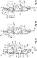
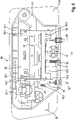
- the handle support 11 itself has an opening 12 , the inner dimensions of which are designed to be complementary to the outer dimensions of the handle part 20 .
- the opening 12 itself is provided with an edge 12.1 in order to make access to the handle device 10, in particular into the interior 11.1 from the outside 11.2, more difficult for unauthorized persons.
- the handle device 10 itself has a front side 10.1 and a back side 10.2, the fictitious planes of the front side 10.11 and the back side 10.2 having a minimum distance, which is also to be referred to as the overall depth 10.3 within the meaning of the invention.
- the corresponding overall depth 10.3 is, for example, in the Figure 3a drawn.
- the handle part 20 initially moves linearly (see arrow 50) out of the handle support 11 through the opening 12.
- the handle part 20 is guided by at least the two levers 13 and 14, which are also referred to as the first lever 13 and the second lever 14.
- the first lever 13 has a fixed fulcrum 13.1 with the handle part 12.
- the second lever 14 also has a fixed fulcrum 14.1 with the handle part 20.
- the two pivot points 13.1 and 14.1 in terms of the installation situation shown from the figures 1 offset in height and side to each other.
- the end of the lever 13 facing away from the handle part 20 is rotatably connected to the handle support 11 via a further fixed (lower) pivot point 13.2.
- the first lever 13 only rotates about the fixed pivot point 13.2 with the handle support 11.
- the second lever 14 on the other hand, only has the upper, fixed pivot point 14.1 with the handle part 20 and is at its end remote from the handle part 20 with a slot 14.2 equipped, which cooperates with a fixed pivot point 14.2 in the form of a bearing pin on the handle support 11 in order to exert a rotary pivoting movement in this area.
- the second lever 14 has an angle 14.4 with two ends at which the two turning/pivoting points are arranged distal to the angle 14.4. During the movement of the handle part 20 from the rest position la into its operating position Ib, the second lever 14 initially rotates only about the pivot point 14.2 or the bearing pin 14.2.
- the handle part 20 first performs a linear movement 50 between the rest position 1a and the operating position 1b. During the further movement of the grip part 20 from the operating position Ib into the release position Ic, the grip part 20 changes from the linear movement 50 to an arcuate (upward) movement 51 (see arrow 51). After the handle part 20 has then been transferred to its release position Ic and a mechanical locking device 80 has been actuated by a connecting element 16, the movable part 70 can be opened.
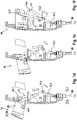
- a seal 11.5 is provided circumferentially in the opening 12, in particular in the edge 12.1, which seal interacts with the handle part 20 in order to close the opening 12.
- the handle part 20 is shown in the rest position la.
- the handle part 20 is shown in an intermediate position between the rest position la and the operating position Ib.
- the handle part 20 is in its operating position Ib.
- the handle part is then shown in its release position 1c, the handle part 20 mechanically interacting with the (purely) mechanical locking device 80 via the connecting element 16, which in the present case is designed as a Bowden cable.
- the mechanical locking device 80 is in the Figures 6 and 7 implied.
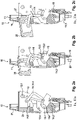
- FIG. 3a, 3b and 3c a further sectional view of the handle device 10 according to the invention is shown.
- the sequence of movements of the handle part 20 from the rest position la through its operating position Ib to its release position Ic is shown.
- a light unit 26 is arranged in the handle part 20, but it can also be arranged optionally or additionally in the handle support 11. How based on Figure 3b and 3c can be seen, the light unit 26 can emit a light cone 26.1 in order to realize a front-end illumination.
- Figures 3a to 3c once again shows the functioning of the transmission lever 15, which interacts with the connecting element 16 for the mechanical locking device 80 via its point of application 15.3.
- the handle support 11 can also be provided with a panel 11.4 in order to cover the movable part 70 in the area of the handle device 10 in an attractive manner. Furthermore, at least one holding means 11.3 for the connecting element 16 or 29 is provided on the handle support 11. In the sectional views of Figures 3a to 3c the corresponding holding means 11.3 for receiving the connecting element 16 on the handle support 11 is clearly visible.
- the handle part 20 has an outwardly directed cavity in which the various sensor elements 23, 24 etc. can be arranged, in particular behind a cover or screen.
- the control unit 25 mentioned can also be accommodated in this cavity, as in FIGS Figures 3 shown.
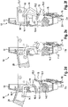
- first lever 13 and the second lever 14 is U-shaped or H-shaped. With the two parallel legs of the U-shaped or H-shaped levers 13, 14, the handle part 20 is encompassed or held on both sides.
- the upper pivot points 13.1 of the first lever 13 and the pivot point 14.1 of the second lever 14.1 are clearly visible.
- the lower pivot points of the two levers 13 and 14 are formed by the axes 13.3 and 14.3, which are each designed to be continuous.
- the axis 13.3, which also serves as a pivot point 13.2 for the lever 13, is provided with a first spring element 17 as a spiral spring, as a result of which the first lever 13 is spring-loaded, whereby the handle part 20 is automatically moved from its rest position la by the first spring element 17 to its operating position Ib is pressed. From this operating position Ib, the handle part 20 can further Handle device 10 according to the invention shown.
- a screen 11.4 is used for the handle support 11, the handle support 11 itself having lattice structures for reinforcement.
- a crash lock 21 is also drawn in, which can interact in a form-fitting manner with the movement mechanism of the handle part 20 in order to prevent unwanted movement of the handle part 20 in the event of an accident.
- FIG 6 1 is a plan view from the outside of a movable part 70, in the form of a motor vehicle door.
- a button 27 or flap 27 or cap 27 is arranged above a mechanical lock cylinder 27 shown in dashed lines.
- flap or cap 27 By pressing this button, flap or cap 27, the handle part 20 can also be unlocked purely mechanically and transferred by the first spring element 27 from the rest position la to the operating position Ib.
- a security system 90 in particular in the form of a central locking system, is also shown. This security system 90 can be used with a mobile ID transmitter 91, which is in the figure 7 is shown, cooperate to effect an electronic authentication or unlocking of the central locking.
Landscapes
- Engineering & Computer Science (AREA)
- Mechanical Engineering (AREA)
- Lock And Its Accessories (AREA)
Description
Die vorliegende Erfindung ist auf eine Griffvorrichtung für eine Schließvorrichtung für ein bewegliches Teil, wie z. B. eine Tür, Klappe oder dergleichen, eines Kraftfahrzeuges gemäß dem Oberbegriff von Anspruch 1 gerichtet. Hierbei kommt ein Griffteil zum Einsatz, das zum beweglichen Teil beweglich lagerbar ist, wobei die Schließvorrichtung über ein Verbindungselement mit dem Griffteil verbindbar ist und das Griffteil zur Betätigung der Schließvorrichtung dient. Das Griffteil kann dabei selbst zwischen einer Ruhestellung und einer Betriebsstellung hin und her bewegbar sein. In der Ruhestellung des Griffteils ist das Griffteil insbesondere strakbündig mit dem beweglichen Teil ausbildbar, worunter zu verstehen ist, dass sich das Griffteil mehr oder weniger flächenbündig mit der Außenseite des beweglichen Teils verbündet. In der Betriebsstellung des Griffteils ist dieses abstehbar aus dem beweglichen Teil, damit es von einem Bediener greifbar ist. Ferner ist die vorliegende Erfindung auch auf ein Verfahren zum Betätigen einer Griffvorrichtung für eine Schließvorrichtung für ein bewegliches Teil gemäß dem Oberbegriff von Anspruch 14 gerichtet.The present invention is directed to a handle device for a locking device for a movable part, such as e.g. B. a door, flap or the like, of a motor vehicle according to the preamble of claim 1 directed. A handle part is used here, which can be movably mounted relative to the movable part, the locking device being able to be connected to the handle part via a connecting element and the handle part serving to actuate the locking device. The grip part itself can be moved back and forth between a rest position and an operating position. In the rest position of the grip part, the grip part can be formed in particular flush with the movable part, which means that the grip part is more or less flush with the outside of the movable part. In the operating position of the handle part, it can be protruded from the movable part so that it can be gripped by an operator. Furthermore, the present invention also relates to a method for actuating a handle device for a Locking device for a movable part according to the preamble of
Aus dem Stand der Technik sind bereits flächenbündige Türaußengriffvorrichtungen bei Fahrzeugen bekannt. Hierbei kommen insbesondere Türgriffvorrichtungen zum Einsatz, die mit einer elektromechanischen Schließvorrichtung zusammenwirken. In diesem Fall braucht die Griffvorrichtung nur aus ihrer Ruhestellung in die Betriebsstellung fahren, in der der Bediener dann durch einfache Berührung oder durch Drücken eines Knopfes ein Öffnungssignal bzw. Auslösesignal für die elektromechanische Schließvorrichtung auslöst, die daraufhin das bewegliche Teil freigibt, wodurch es durch den Bediener zu öffnen ist. Dabei kann der Bediener an dem ausgefahrenen Griffteil in der Betriebsstellung eingreifen, um das bewegliche Teil aufzuschwenken.Flush exterior door handle devices in vehicles are already known from the prior art. Here, in particular, door handle devices are used that interact with an electromechanical locking device. In this case, the handle device only needs to be moved from its rest position to the operating position, in which the operator then triggers an opening signal or trigger signal for the electromechanical locking device by simply touching it or by pressing a button, which then releases the moving part, whereby it can be pushed through the operator is to be opened. The operator can intervene on the extended handle part in the operating position in order to swivel open the movable part.
Derartige Türgriffvorrichtungen weisen jedoch den Nachteil auf, dass bei einem Stromausfall das Fahrzeug die elektromechanische Schließvorrichtung nicht ohne Weiteres zu betätigen ist. Häufig benötigen derartige Griffvorrichtungen auch einen großen Bauraum, der gerade bei Kraftfahrzeugtüren als bewegliches Teil nur knapp bemessen ist. Häufig können derartige Türgriffvorrichtungen nicht überall an einer Kraftfahrzeugtür angeordnet werden, da der Platzbedarf häufig nicht ausreichend ist.However, such door handle devices have the disadvantage that in the event of a power failure, the vehicle cannot easily actuate the electromechanical locking device. Frequently, handle devices of this type also require a large amount of installation space, which is only tightly dimensioned as a moving part, especially in the case of motor vehicle doors. Door handle devices of this type often cannot be arranged everywhere on a motor vehicle door, since the space requirement is often not sufficient.
Aus der
Aufgabe der vorliegenden Erfindung ist es somit eine Griffvorrichtung sowie ein Verfahren zur Betätigung einer derartigen Griffvorrichtung bereitzustellen, welches zumindest teilweise die Nachteile aus dem Stand der Technik behebt. Insbesondere ist es eine Aufgabe der vorliegenden Erfindung, eine rein mechanische Griffvorrichtung zu schaffen, die einen hohen Betätigungskomfort für einen Bediener ermöglicht. Des Weiteren ist es insbesondere eine Aufgabe der vorliegenden Erfindung, dass die erfindungsgemäße Griffvorrichtung möglichst an jeder Stelle am beweglichen Teil, insbesondere einer Kraftfahrzeugtür, Klappe oder dergleichen, anordbar ist. Zusätzlich ist es eine Aufgabe der vorliegenden Erfindung, bei einer derartigen Griffvorrichtung die Aerodynamik des Fahrzeugs zu verbessern und die Unfallgefahr, insbesondere für Fußgänger, zu reduzieren.The object of the present invention is therefore to provide a handle device and a method for actuating such a handle device, which at least partially eliminates the disadvantages of the prior art. In particular, it is an object of the present invention to create a purely mechanical handle device that allows a high level of operating comfort for an operator. Furthermore, it is in particular an object of the present invention that the handle device according to the invention can be arranged at any point on the movable part, in particular a motor vehicle door, flap or the like. In addition, it is an object of the present invention to improve the aerodynamics of the vehicle with such a handle device and to reduce the risk of accidents, in particular for pedestrians.
Die zuvor genannte Aufgabe wird durch eine Griffvorrichtung mit den Merkmalen aus dem unabhängigen Vorrichtungsanspruch, insbesondere mit den Merkmalen aus dem kennzeichnenden Teil, gelöst. Insbesondere wird zur Lösung der Aufgabe ein Verfahren zur Betätigung einer derartigen Griffvorrichtung mit den Merkmalen des Anspruchs 14, insbesondere aus dem kennzeichnenden Teil, vorgeschlagen. In den abhängigen Vorrichtungs- und Verfahrensansprüchen sind bevorzugte Weiterbildungen der Erfindung aufgeführt. Merkmale, die zu der erfindungsgemäßen Griffvorrichtung offenbart werden, gelten dabei auch für das erfindungsgemäße Betätigungsverfahren und umgekehrt. Außerdem kann das erfindungsgemäße Betätigungsverfahren der erfindungsgemäßen Griffvorrichtung realisiert werden.The above object is achieved by a handle device with the features of the independent device claim, in particular with the features of the characterizing part, solved. In particular, a method for actuating such a handle device with the features of
Im nachfolgenden Text werden geometrische Angaben zur erfindungsgemäßen Griffvorrichtungen immer im zusammengebauten Zustand beschrieben. Außerdem beziehen sich derartige geometrische Angaben auf die Einbausituation der erfindungsgemäßen Griffvorrichtung am Fahrzeug, wie sie beispielhaft in den Figuren dargestellt sind.In the following text, geometric information on the handle devices according to the invention are always described in the assembled state. In addition, such geometric information relates to the installation situation of the handle device according to the invention on the vehicle, as shown by way of example in the figures.
Bei der erfindungsgemäßen Griffvorrichtung für eine Schließvorrichtung für ein bewegliches Teil, wie z. B. eine Tür, Klappe oder dergleichen, bei einem Fahrzeug, kommt ein Griffteil zum Einsatz, das zu dem beweglichen Teil beweglich lagerbar ist. Dieses Griffteil ist über ein Verbindungselement mit der Schließvorrichtung verbindbar und dient dazu die Schließvorrichtung zu betätigen, wenn ein Bediener das Griffteil bedient. Das Griffteil ist zumindest zwischen einer Ruhestellung und einer Betriebsstellung bewegbar, wobei in der Ruhestellung das Griffteil insbesondere strakbündig mit dem beweglichen Teil ausbildbar ist und wobei in der Betriebsstellung das Griffteil aus dem beweglichen Teil derart abstehbar ist, dass es von dem Bediener greifbar ist. Unter "strakbündig" wird dabei verstanden, dass das Griffteil mehr oder weniger flächenbündig in der Außenseite bzw. Oberfläche des beweglichen Teils integriert ist. Somit ragt das Griffteil nicht störend aus dem beweglichen Teil heraus, wenn es eben nicht benutzt wird und in seiner Ruhestellung verharrt. Somit wird die Aerodynamik des Fahrzeugs in diesem Bereich deutlich verbessert, wodurch auch keine störenden Windgeräusche entstehen können. Außerdem wird auch zuverlässig eine Verletzung von Fußgängern vermindert, da auch hier das Griffteil nicht störend aus dem beweglichen Teil herausragt. Ferner ist es bei der erfindungsgemäßen Griffvorrichtung vorgesehen, dass das Griffteil aus seiner Betriebsstellung in eine zusätzlich Auslösestellung bewegbar ist, in der eine mechanische Betätigung des Griffteils auf das Verbindungselement übertragbar ist, wodurch die Schließvorrichtung selber betätigbar ist. Durch die Überführung des Griffteils von der Betriebsstellung in die zusätzliche Auslösestellung wird eine Betätigungskraft über das Verbindungselement auf die Schließvorrichtung übertragen, wodurch diese sich öffnen lässt. Dabei gibt die Schließvorrichtung eine Drehfalle frei, wodurch ein Formschluss mit einem U-förmigen Bügel am Fahrzeug freigeben wird, so dass sich das bewegliche Teil nach der Öffnung der Schließvorrichtung selber öffnen lässt. Hierzu ist noch ein Zug des Bedieners an dem beweglichen Teil, über das Griffteil, erforderlich. Alleine zu diesem Zweck ist es notwendig, dass das Griffteil in seiner Betriebsstellung aus dem beweglichen Teil greifbar herausragt. Die rein mechanische Betätigung der Schließvorrichtung weist den Vorteil auf, dass sich das bewegliche Teil auch bei einem Stromausfall der Fahrzeugelektronik oder einer Elektronik für die Griffvorrichtung noch auf einfache Art und Weise sowie komfortabel öffnen lässt.In the handle device according to the invention for a locking device for a movable part, such as. B. a door, flap or the like, in a vehicle, a handle part is used, which is movably mounted to the movable part. This handle part can be connected to the locking device via a connecting element and is used to actuate the locking device when an operator operates the handle part. The handle part can be moved at least between a rest position and an operating position, with the handle part being able to be configured in the rest position, in particular flush with the movable part, and with the handle part being able to protrude from the movable part in the operating position in such a way that it can be gripped by the operator. “Flush with the street” is understood to mean that the handle part is integrated more or less flush with the outside or surface of the movable part. Thus, the handle part does not protrude from the movable part in a disturbing manner when it is not in use and remains in its rest position. This significantly improves the aerodynamics of the vehicle in this area, which means that no disturbing wind noise can occur. In addition, injuries to pedestrians are also reliably reduced, since the handle part does not protrude from the movable part in a disruptive manner here either. Furthermore, the handle device according to the invention provides that the handle part can be moved from its operating position into an additional release position in which mechanical actuation of the handle part can be transferred to the connecting element, whereby the locking device itself can be actuated. Through the transfer of the handle part from the operating position to the additional release position, an actuating force is transmitted via the connecting element to the locking device, as a result of which it can be opened. The locking device releases a rotary latch, which releases a form fit with a U-shaped bracket on the vehicle, so that the moving part can be opened after the locking device has been opened. To do this, the operator still has to pull the movable part via the handle part. For this purpose alone, it is necessary for the handle part to protrude from the movable part so that it can be grasped in its operating position. The purely mechanical actuation of the locking device has the advantage that the movable part can still be opened easily and conveniently even in the event of a power failure of the vehicle electronics or electronics for the handle device.
Damit das Griffteil überhaupt aus dem Griffträger ausfahren kann, ist ein Durchbruch im Griffträger vorgesehen, wobei erfindungsgemäß das Griffteil sowohl in der Betriebsstellung als auch in der Auslösestellung den Durchbruch verdeckt. Damit sind Manipulationen der erfindungsgemäßen Griffvorrichtung ausgeschlossen. Hierbei ist es insbesondere vorstellbarr, dass der Durchbruch einen Rand aufweist, der ins Innere vom Griffträger ragt, um somit einen verbesserten Schutz zu bewirken. Der Rand kann gleichzeitig als Verstärkung des Durchbruches dienen und kann auch Kippstabilität des Griffteils bei der Bewegung zum Griffträger verbessern.So that the grip part can be extended out of the grip support at all, an opening is provided in the grip support, the grip part according to the invention covering the opening both in the operating position and in the release position. This rules out manipulation of the handle device according to the invention. In this context, it is particularly conceivable that the opening has an edge that protrudes inwards from the handle support, in order thus to provide improved protection. At the same time, the edge can serve to reinforce the opening and can also improve the tilting stability of the handle part when moving towards the handle carrier.
Ferner kann bei der erfindungsgemäßen Griffvorrichtung vorgesehen sein, dass das Griffteil zwischen der Ruhestellung und der Betriebsstellung linear bewegbar ist. Damit vollzieht das Griffteil eine kürzest mögliche Bewegungsstrecke zwischen der Ruhestellung und der Betriebsstellung, wodurch der Aufbau der gesamten Griffvorrichtung möglichst kompakt und in seiner Bautiefe minimierbar ist. Ferner ist es denkbar, dass das Griffteil zwischen der Betriebsstellung und der Auslösestellung bogenförmig, insbesondere bogenförmig nach oben hin oder nach unten hin, bewegbar ist. Da in der Regel die Griffvorrichtung am Fahrzeug recht niedrig für eine erwachsene Person angeordnet ist, entspricht gerade eine nach oben hin bogenförmige Bewegung des Griffteils zwischen der Betriebsstellung und der Auslösestellung einer ergonomischen und leichten Bedienung durch den Bediener. Hierdurch wird der Betätigungskomfort der Griffvorrichtung deutlich verbessert. Außerdem lässt sich aufgrund der besonderen Kinematik innerhalb der Griffvorrichtung die Zugkraft am Griffteil zwischen der Betriebsstellung und der Außenstellung derart optimieren, dass eine maximale Zugkraft über das vorgesehene Verbindungselement auf rein mechanische Schließvorrichtung übertragbar ist. Damit reicht eine leichte Zugkraft an dem Griffteil aus, um die Schließvorrichtung rein mechanisch öffnen zu können.Furthermore, it can be provided in the handle device according to the invention that the handle part can be moved linearly between the rest position and the operating position. The handle part thus completes the shortest possible movement distance between the rest position and the operating position, as a result of which the structure of the entire handle device is as compact as possible and its overall depth can be minimized. Furthermore, it is conceivable that the handle part can be moved in an arc between the operating position and the release position, in particular in an arc-shaped upward or downward direction. Since the handle device on the vehicle is usually arranged quite low for an adult person, an upward arcuate movement of the handle part between the operating position and the release position corresponds to ergonomic and easy operation by the operator. This significantly improves the operating comfort of the handle device. In addition, due to the special kinematics within the handle device, the tensile force on the handle part between the operating position and the external position can be optimized in such a way that a maximum tensile force can be transferred to a purely mechanical locking device via the connecting element provided. A slight pulling force on the handle part is therefore sufficient to be able to open the locking device purely mechanically.
Des Weiteren ist es bei der erfindungsgemäßen Griffvorrichtung vorgesehen, dass das Griffteil durch einen Griffträger am beweglichen Teil lagerbar ist. Somit wird das Griffteil nicht direkt zu dem beweglichen Teil, sondern vielmehr indirekt über den Griffträger an dem beweglichen Teil angeordnet bzw. damit verbunden. Dabei kann es ferner vorgesehen sein, dass das Griffteil über zwei Hebel am Griffträger bewegbar angeordnet ist. Diese beiden Hebel können nebeneinander angeordnet sein und umgreifen das Griffteil beidseitig, um eine besonders stabile Führung des Griffteils zum Griffträger zu bewirken. Damit wird auch ein Verkanten des Griffteils während seiner Verstellung zuverlässig vermieden. Darüber hinaus hätte z. B. eine Linearführung zwischen Griffträger und Griffteil den Nachteil, dass diese bei entsprechenden Witterungsverhältnissen schnell einfrieren kann. Somit ist es zweckmäßig, wenn das Griffteil ausschließlich über die beiden Hebel bewegbar am Griffträger gehalten ist. Hierbei ist es denkbar, dass zumindest einer der Hebel jeweils über eine durchgehende Achse beidseitig mit dem Griffträger bewegbar verbunden ist. Aufgrund der durchgehenden Achse ist eine einfache Montage und eine besonders zuverlässige Anordnung der beiden Hebel am Griffträger realisierbar. Außerdem können die Drehachsen auch der Aufnahme von Federelementen dienen, die nachfolgend noch näher beschrieben werden. Ferner dienen die entsprechenden Achsen auch zur Erhöhung der Stabilität der gesamten Griffvorrichtung.Furthermore, it is provided in the handle device according to the invention that the handle part can be mounted on the movable part by a handle support. Thus, the handle part is not arranged directly on the movable part, but rather indirectly via the handle support on the movable part or connected thereto. It can also be provided that that the handle part is movably arranged via two levers on the handle support. These two levers can be arranged next to one another and grip the handle part on both sides in order to bring about a particularly stable guidance of the handle part to the handle support. This also reliably prevents the handle part from tilting during its adjustment. In addition, z. B. a linear guide between the handle support and handle part has the disadvantage that it can quickly freeze in the right weather conditions. Thus, it is expedient if the handle part is held on the handle carrier in such a way that it can be moved only via the two levers. It is conceivable here that at least one of the levers is movably connected to the handle support on both sides via a continuous axis. Due to the continuous axle, simple assembly and a particularly reliable arrangement of the two levers on the handle support can be implemented. In addition, the axes of rotation can also serve to accommodate spring elements, which are described in more detail below. Furthermore, the corresponding axes also serve to increase the stability of the entire handle device.
Des Weiteren ist es im Rahmen der Erfindung denkbar, dass die beiden Hebel zur Führung des Griffteils unterschiedlich voneinander angeordnete Dreh-/Schwenkpunkte aufweisen. Unter den unterschiedlich voneinander angeordneten Dreh-/Schwenkpunkten wird dabei verstanden, dass somit die entsprechenden Punkte sich nicht auf einer gemeinsamen Drehachse befinden. Vielmehr wird aufgrund der besonderen Kinematik erreicht, dass über die beiden Hebel das Griffteil zunächst die Linearbewegung zwischen der Ruhestellung und der Betriebsstellung vollzieht, um dann zwischen der Betriebsstellung und der Auslösestellung eine bogenförmige Bewegung zu ermöglichen. Ferner ist es möglich, dass die beiden Hebel seitlich nebeneinander angeordnet sind und nicht direkt miteinander verbunden sind. Vielmehr erfolgt eine Verbindung der Hebel über die Anordnung am Griffteil bzw. am Griffträger, die jedoch in jedem Falle indirekt ist. Auch können die beiden Hebel das Griffteil jeweils beidseitig, insbesondere von außen, umfassen bzw. einfassen. Dabei sind die beiden Hebel im Wesentlichen H-förmig oder U-förmig ausgestaltet, wobei das Griffteil zwischen den parallelen Schenkeln der beiden Hebel angeordnet ist. Durch die konkret ausgestalteten Hebel wird bereits das erwähnte Problem des Verkantens des Griffes beim Ausfahren und bei der Betätigung zuverlässig vermieden.Furthermore, it is conceivable within the scope of the invention that the two levers for guiding the handle part have rotating/pivoting points arranged differently from one another. The differently arranged rotation/pivot points mean that the corresponding points are not located on a common axis of rotation. Rather, due to the special kinematics, the handle part first performs the linear movement between the rest position and the operating position via the two levers, in order to then enable an arcuate movement between the operating position and the release position. It is also possible for the two levers to be arranged side by side and not directly connected to one another. Rather, the levers are connected via the arrangement on the handle part or on the handle support, which is however indirect in any case. The two levers can also encompass or enclose the handle part on both sides, in particular from the outside. The two levers are essentially H-shaped or U-shaped, with the grip part being arranged between the parallel legs of the two levers. The specifically designed lever reliably avoids the aforementioned problem of the handle tilting when it is extended and actuated.
Auch ist es bei der Erfindung denkbar, dass der erste Hebel als Antriebshebel ausgebildet ist, um das Griffteil zumindest zwischen der Ruhestellung und der Betriebsstellung zu bewegen. Dabei kann eine Antriebskraft auf den Antriebshebel bzw. den ersten Hebel dazu dienen, das Griffteil aus seiner Ruhestellung automatisch bzw. selbstständig in die Betriebsstellung zu überführen. Hierzu kann ein erstes Federelement derart am ersten Hebel angreifen, dass das Griffteil von der Ruhestellung in die Betriebsstellung selbstständig überführbar ist. Somit dient das Federelement zur Erzeugung der bereits erwähnten Antriebskraft. Diese Ausgestaltung weist den Vorteil auf, dass keine motorische Kraft notwendig ist, für die ggf. auch elektrische Energie bereitgestellt werden muss, um das Griffteil aus der Ruhestellung in die Betriebsstellung zu überführen.It is also conceivable with the invention that the first lever is designed as a drive lever in order to move the handle part at least between the rest position and the operating position. A drive force on the drive lever or the first lever can be used to automatically or independently transfer the handle part from its rest position into the operating position. For this purpose, a first spring element can act on the first lever in such a way that the handle part can be independently transferred from the rest position to the operating position. Thus, the spring element is used to generate the already mentioned driving force. This configuration has the advantage that no motor power is required, for which electrical energy may also have to be provided in order to transfer the handle part from the rest position to the operating position.
Des Weiteren ist es erfindungsgemäß denkbar, dass am ersten Hebel ein Antrieb, insbesondere ein elektromechanischer Antrieb in Form eines Elektromotors, angreift, wodurch das Griffteil zumindest zwischen der Ruhestellung und der Betriebsstellung bewegbar ist. Hierbei ist es von Vorteil, wenn der Antrieb den ersten Hebel von der Betriebsstellung in die Ruhestellung, überführt, womit gemeint ist, dass quasi der Antrieb das Griffteil einzieht und nicht ausfährt. Insbesondere ist es denkbar, dass der Antrieb eine Antriebskraft erzeugt, die entgegengesetzt einer Federkraft vom ersten Federelement gerichtet ist. Somit dient die Feder zum automatischen Ausfahren des Griffteils von der Ruhestellung in die Betriebsstellung und die Antriebskraft vom Antrieb zieht das Griffteil von der Betriebsstellung gegen die Federkraft des ersten Federelements zurück in die Ruhestellung. Idealerweise ist der Antrieb selbsthemmend aufgebaut, so dass er nachdem das Griffteil seine Ruhestellung erreicht hat, stromlos geschaltet werden kann und trotzdem in dieser Ruhestellung verharrt. Auch ist es denkbar, dass eine Verriegelung des Griffteils in der Ruhestellung erfolgt, so dass nur die Verriegelung überwunden werden muss, damit das erste Federelement das Griffteil automatisch von der Ruhestellung in die Betriebsstellung überführt.Furthermore, it is conceivable according to the invention for a drive, in particular an electromechanical drive in the form of an electric motor, to act on the first lever, as a result of which the handle part can be moved at least between the rest position and the operating position. It is advantageous here if the drive transfers the first lever from the operating position to the rest position, which means that the drive pulls the handle part in and does not extend it. In particular, it is conceivable that the drive generates a driving force that is directed opposite to a spring force from the first spring element. Thus, the spring is used to automatically extend the handle part from the rest position to the operating position and the driving force from the drive pulls the handle part from the operating position against the spring force of the first spring element back into the rest position. Ideally, the drive is self-locking so that it can be switched off after the handle part has reached its rest position and still remain in this rest position. It is also conceivable that the handle part is locked in the rest position, so that only the lock has to be overcome so that the first spring element automatically transfers the handle part from the rest position to the operating position.
Auch ist es im Rahmen der Erfindung vorstellbar, dass der zweite Hebel als Betätigungshebel ausgebildet ist, um die mechanische Bewegung des Griffteils von der Betriebsstellung zur Auslösestellung auf das Verbindungselement zu übertragen. Somit dient der zweite Hebel nicht nur zur Führung des Griffteils, sondern dient gleichzeitig dazu, auch gerade die insbesondere bogenförmige Bewegung des Griffteils auf das Verbindungselement zu übertragen. Auch ist es denkbar, dass eine Betätigung des Verbindungselements erst nach Erreichen der Betriebsstellung vom Griffteil möglich ist. Somit verursacht die zunächst erfolgte Bewegung des zweiten Hebels zwischen der Ruhestellung und der Betriebsstellung des Griffteils keine mechanische Übertragung auf das Verbindungselement. Damit ist sichergestellt, dass in jedem Fall das bewegliche Teil durch die Schließvorrichtung verschlossen bleibt, auch wenn das Griffteil zunächst aus seiner Ruhestellung in die Betriebsstellung überführt wird. Ferner ist es denkbar, dass insbesondere der zweite Hebel von der Betriebsstellung zur Auslösestellung eine Höhenbewegung zum Griffträger erfährt. Mit anderen Worten: der Hebel wird im Verhältnis zum Griffträger durch den Wechsel zur Betriebsstellung zur Auslösestellung angehoben. Gerade diese Hebelbewegung kann idealerweise auf das Verbindungselement zur Betätigung der Schließvorrichtung übertragen werden.It is also conceivable within the scope of the invention for the second lever to be designed as an actuating lever in order to transfer the mechanical movement of the handle part from the operating position to the release position to the connecting element. Thus, the second lever is not only used to guide the handle part, but also serves at the same time to control the particularly curved movement of the handle part on the transfer connection element. It is also conceivable that the connecting element can only be actuated after the handle part has reached the operating position. Thus, the initial movement of the second lever between the rest position and the operating position of the handle part does not cause any mechanical transmission to the connecting element. This ensures that the movable part remains closed by the locking device in any case, even if the handle part is initially transferred from its rest position to the operating position. It is also conceivable that in particular the second lever experiences a vertical movement from the operating position to the release position in relation to the handle support. In other words, the lever is raised relative to the handle support by the change from the operating position to the release position. Ideally, this lever movement can be transferred to the connecting element for actuating the locking device.
Ferner ist es im Rahmen der Erfindung vorstellbar, dass der zweite Hebel winkelförmig, insbesondere rechteckwinkelförmig ausgestaltet ist. Durch diese winkelförmige Anordnung des zweiten Hebels kann das bewegbare Griffteil auf besonders einfache Art und Weise am Griffträger beweglich angeordnet werden. Dabei können beim zweiten Hebel die Dreh- und Schwenkpunkte zum Griffträger jeweils im distalen Abstand zum Winkel bzw. am Ende des Winkels vorgesehen sein. Hierdurch wird die Wirkung des zweiten Hebels besonders effektiv ausgenutzt. Idealerweise kann zumindest ein Dreh-Schwenkpunkt des zweiten Hebels zum Griffträger als Dreh-Schwenklager zum Griffträger ausgestaltet sein, um auch die bereits beschriebene Höhenbewegung des zweiten Hebels zum Griffträger zu ermöglichen. Zweckmäßigerweise ist der untere Dreh-Schwenkpunkt als Langlochlager am zweiten Hebel ausgestaltet, der mit einem festen Drehpunkt zum Griffträger formschlüssig zusammenwirkt. Ein oberer Drehpunkt am zweiten Hebel kann als fester Drehpunkt zum Griffträger als Drehlager ausgestaltet sein. Durch das Zusammenspiel der beiden ersten und zweiten Hebel wird eine besonders elegante Kinematik zur Führung und Lagerung des Griffteils im Verhältnis zum Griffträger erzeugt. Insbesondere wird somit der Bauraum der erfindungsgemäßen Griffvorrichtung minimal ausgestaltet, wodurch die gesamte Griffvorrichtung örtlich beliebig am beweglichen Teil platzierbar ist.Furthermore, it is conceivable within the scope of the invention for the second lever to be designed in the shape of an angle, in particular a right angle. Due to this angular arrangement of the second lever, the movable handle part can be movably arranged on the handle carrier in a particularly simple manner. In the case of the second lever, the turning and pivoting points for the handle support can each be provided at a distal distance from the angle or at the end of the angle. As a result, the effect of the second lever is used particularly effectively. Ideally, at least one pivot point of the second lever relative to the handle carrier can be configured as a rotary pivot bearing relative to the handle carrier, in order to also enable the vertical movement of the second lever relative to the handle carrier, which has already been described. The lower pivot point is expediently designed as a slot bearing on the second lever, which interacts with a fixed pivot point for the handle support in a form-fitting manner. An upper fulcrum on the second lever can be designed as a fixed fulcrum to the handle support as a pivot bearing. The interaction of the two first and second levers creates particularly elegant kinematics for guiding and mounting the handle part in relation to the handle carrier. In particular, the installation space of the handle device according to the invention is designed to be minimal, as a result of which the entire handle device can be placed anywhere on the movable part.
Ferner ist es erfindungsgemäß vorstellbar, dass der zweite Hebel indirekt über einen Übertragungshebel mit dem Verbindungselement mechanisch zusammenwirkt, um insbesondere den Hebel zumindest teilweise vom Verbindungselement zu entkoppeln. Gerade durch den Einsatz des Übertragungshebels kann die Zugkraft, die ein Bediener auf das Griffteil ausübt, über den zweiten Hebel auf den Übertragungshebel erhöht werden, wodurch sich der Bedienkomfort der gesamten Griffvorrichtung erhöhen lässt. Ferner kann ein zweites Federelement mit dem Übertragungshebel zusammenwirken, um den Übertragungshebel in seine Ruheposition zu bewegen. Durch das zweite Federelement soll verhindert werden, dass kleine Erschütterungen am Griffteil, die insbesondere in der Auslösestellung wirken können, zu einem ungewollten Auslösen der Schließvorrichtung führen können. Auch kann eine bogenförmige Führung zwischen dem zweiten Hebel und dem Übertragungshebel vorhanden sein, um einen Freilauf zwischen dem zweiten Hebel und dem Übertragungshebel zu bilden. Dieser Freilauf ermöglicht, dass der zweite Hebel bei einer Bewegung des Griffteils von der Ruhestellung in die Betriebsstellung keine mechanische Übertragung auf den Übertragungshebel erzeugt. Ansonsten könnte es zu einer Fehlauslösung kommen, die in diesem Fall zu vermeiden ist. Zweckmäßigerweise kann der Übertragungshebel einen festen Drehpunkt zum Griffträger aufweisen. Des Weiteren ist es zweckmäßig, wenn der Übertragungshebel zumindest in seiner Ruheposition an einem Anschlag am Griffträger anliegt. Auch kann ein zweiter Anschlag zwischen Griffträger und Übertragungshebel vorgesehen sein, damit der Übertragungshebel nicht zu weit um den vorhandenen Drehpunkt mit dem Griffträger gedreht wird, wodurch bspw. eine Überbelastung beim Verbindungselement entstehen kann.Furthermore, it is conceivable according to the invention that the second lever interacts mechanically with the connecting element indirectly via a transmission lever in order to in particular to decouple the lever at least partially from the connecting element. It is precisely through the use of the transmission lever that the tensile force that an operator exerts on the handle part can be increased via the second lever on the transmission lever, as a result of which the ease of use of the entire handle device can be increased. Furthermore, a second spring element can interact with the transmission lever in order to move the transmission lever into its rest position. The second spring element is intended to prevent small vibrations on the handle part, which can act in particular in the release position, from leading to an unwanted release of the locking device. There can also be an arcuate guide between the second lever and the transmission lever in order to form a freewheel between the second lever and the transmission lever. This freewheel means that the second lever does not generate any mechanical transmission to the transmission lever when the handle part moves from the rest position to the operating position. Otherwise, false triggering could occur, which should be avoided in this case. The transmission lever can expediently have a fixed pivot point relative to the handle support. Furthermore, it is expedient if the transmission lever rests against a stop on the handle support, at least in its rest position. A second stop can also be provided between the handle support and the transmission lever, so that the transmission lever is not rotated too far about the existing pivot point with the handle support, which can result in an overload on the connecting element, for example.
Zweckmäßigerweise kann es vorgesehen sein, dass ein Rand vom Durchbruch im Griffträger für das Griffteil kanalartig, insbesondere vollumfänglich ins Innere ausgestaltet ist, um mit den zuvor beschriebenen Bruchschutz der erfindungsgemäßen Griffvorrichtung sowie im beweglichen Teil vorgesehenen Schließvorrichtung zu verbessern. Auch kann der Rand ein Führungsmittel aufweisen, um das Griffteil zu führen. Dieses Führungsmittel kann optional zu den beiden Hebeln vorgesehen sein und entweder links- und/oder rechtsseitig bzw. oben und/oder unten zwischen dem Rand und dem Griffteil angeordnet werden. Dabei kann eine Nut als Führungsmittel mit einem Führungszapfen als Gegenführungsmittel zwischen Griffteil und Rand vorhanden sein. Auch ist es denkbar, dass im Rand vom Durchbruch eine Dichtung im Griffteil, zumindest in der Ruhestellung, abdichtend zusammenwirkt. Idealerweise ist die Dichtung so zwischen Rand und Griffteil vorgesehen, dass auch eine Abdichtung des Griffteils in der Betriebsstellung vorhanden ist. Dabei ist es auch denkbar, dass die Dichtung außenseitig am Griffteil angeordnet ist und mit dem Rand vom Durchbruch zusammenwirkt. Durch die Dichtung soll verhindert werden, dass Feuchtigkeit, Schmutz und Dreck sowie weitere störende Stoffe in das Innere der erfindungsgemäßen Griffvorrichtung eindringen können. Außerdem können durch die Griffvorrichtung auch weiterhin Windgeräusche zuverlässig vermieden werden. Selbstverständlich können auch zwei Dichtungen vorgesehen sein.Appropriately, it can be provided that an edge of the opening in the handle support for the handle part is designed like a channel, in particular completely inside, in order to with the previously described protection against breakage of the handle device according to the invention as well to improve the locking device provided in the moving part. The edge can also have a guide means to guide the handle part. This guiding means can optionally be provided for the two levers and can be arranged either on the left and/or right side or above and/or below between the edge and the handle part. A groove can be present as a guide means with a guide pin as a counter-guide means between the grip part and the edge. It is also conceivable that a seal in the handle part, at least in the rest position, acts together in a sealing manner in the edge of the opening. Ideally, the seal is provided between the edge and the grip part in such a way that the grip part is also sealed in the operating position. It is also conceivable that the seal is arranged on the outside of the handle part and interacts with the edge of the opening. The seal is intended to prevent moisture, dirt and grime and other disruptive substances from penetrating into the interior of the handle device according to the invention. In addition, wind noise can also be reliably avoided by the handle device. Of course, two seals can also be provided.
Um die Sicherheit der erfindungsgemäßen Griffvorrichtung zu erhöhen, kann zumindest eine Crashsperre und/oder ein Massenausgleichsgewicht vorhanden sein. Dabei soll die Crashsperre und/oder das Massenausgleichsgewicht dazu dienen, das Griffteil bei einem Crash möglichst in der Ruhestellung zu fixieren. Die Crashsperre kann dabei insbesondere formschlüssig das Griffteil zum Griffträger mechanisch blockieren, wobei der konkrete Formschluss zwischen Crashsperre und Griffteil auch an einem der beiden Hebel erfolgen kann. Die Crashsperre kann aber auch direkt mit dem Griffteil in der Ruhestellung formschlüssig zusammenwirken. Das bereits erwähnte Massenausgleichsgewicht kann ebenfalls zumindest an einem der beiden Hebel vorgesehen sein, um seine gewünschte Wirkung zu entfalten. Dabei ist es denkbar, dass das Massenausgleichsgewicht zumindest in einem der beiden Hebel integriert ist.In order to increase the safety of the handle device according to the invention, at least one crash lock and/or a mass balance weight can be present. The crash lock and/or the mass balance weight should serve to fix the handle part in the rest position as far as possible in the event of a crash. The crash lock can in particular mechanically block the handle part in a form-fitting manner with respect to the handle carrier, with the specific form fit between the crash lock and the handle part also being able to take place on one of the two levers. However, the crash lock can also interact directly with the grip part in the rest position in a form-fitting manner. The mass balance weight already mentioned can also be provided on at least one of the two levers in order to develop its desired effect. It is conceivable that the mass balance weight is integrated in at least one of the two levers.
Um den Komfort der erfindungsgemäßen Griffvorrichtung weiterhin zu verbessern, kann es vorgesehen sein, dass wenigstens ein erstes Sensorelement vorhanden ist, um die Vorrichtung, ein Sicherheitssystem und/oder die Fahrzeugelektronik anzusteuern. So ist es bspw. denkbar, dass durch das Sensorelement eine Annäherung eines Bedieners erfassbar ist, wodurch das Griffteil der Griffvorrichtung selbstständig von der Ruhestellung in die Betriebsstellung überführbar ist. Auch kann durch diese Annäherung bspw. eine Kommunikation zwischen einem fahrzeugseitigem Sicherheitssystem und einem mobilen ID-Geber, den ein Bediener mit sich trägt, ausgelöst werden, um die Griffvorrichtung bspw. zu entriegeln. Hierbei kann das Sensorelement zumindest als Näherungssensor, Eingriffssensor, Antenne, Signalgeber, Lichtsensor oder Temperatursensor ausgestaltet sein. Durch die unterschiedlichen Sensorelemente können verschiedene Komfortwünsche bei der erfindungsgemäßen Griffvorrichtung realisiert werden. So kann bspw. der Temperatursensor dazu dienen, dass die Griffvorrichtung bei Temperaturen um den Gefrierpunkt aufgeheizt oder zumindest in Vibration versetzt wird. Der Lichtsensor kann dazu dienen, eine Leuchteinheit anzuschalten, wenn die Lichtverhältnisse es erforderlich machen. Die Antenne kann die Kommunikation mit dem mobilen ID-Geber oder weiteren Informationsgebern dienen. Zweckmäßigerweise ist zumindest auch eine Steuereinheit innerhalb der Griffvorrichtung vorgesehen, die mit dem Sensorelement datentechnisch verbunden ist. Durch diese Steuereinheit können die Daten des Sensorelements empfangen und ausgewertet werden, um die entsprechend gewünschten Funktionen bei der erfindungsgemäßen Griffvorrichtung oder der Fahrzeugelektronik oder des Sicherheitssystems auszulösen.In order to further improve the comfort of the handle device according to the invention, it can be provided that at least one first sensor element is present in order to control the device, a safety system and/or the vehicle electronics. For example, it is conceivable that the approach of an operator can be detected by the sensor element, whereby the handle part of the handle device independently moves from the rest position to the Operating position can be transferred. This approach can also trigger communication, for example, between a vehicle-side security system and a mobile ID transmitter that an operator carries with him, in order to unlock the handle device, for example. In this case, the sensor element can be designed at least as a proximity sensor, intervention sensor, antenna, signal transmitter, light sensor or temperature sensor. Due to the different sensor elements, different comfort requirements can be realized with the handle device according to the invention. For example, the temperature sensor can be used to heat the handle device or at least set it to vibrate at temperatures around freezing point. The light sensor can be used to switch on a lighting unit when the lighting conditions make it necessary. The antenna can be used for communication with the mobile ID transmitter or other information transmitters. At least one control unit is expediently also provided within the handle device, which is connected to the sensor element in terms of data technology. The data from the sensor element can be received and evaluated by this control unit in order to trigger the correspondingly desired functions in the handle device according to the invention or the vehicle electronics or the safety system.
Um den Komfort der Griffvorrichtung weiter zu verbessern, können wenigstens zwei Sensorelemente vorhanden sein, wobei zumindest ein Sensorelement als kapazitiver Sensor ausgestaltet ist, um bspw. eine Annäherung eines Bedieners an die Griffvorrichtung messtechnisch zu erfassen. Auch ist es denkbar, dass zumindest beide Sensorelemente als kapazitive Sensoren ausgestaltet sind, wobei das erste Sensorelement eine Annäherung eines Bedieners an das Fahrzeug erfasst und das zweite Sensorelement ein Eingreifen eines Bedieners in eine Griffmulde des Griffteils. Zusätzlich kann auch ein weiteres Sensorelement vorgesehen sein, wie z. B. ein Hallsensor, der z. B. die Stellung des Griffteils überwacht oder eine Antenne, die mit einem externen ID-Geber einen Datenaustausch ermöglicht. Anhand dieser Informationen lassen sich gezielte Funktionen bei der erfindungsgemäßen Griffvorrichtung bzw. beim Fahrzeug realisieren.In order to further improve the comfort of the handle device, at least two sensor elements can be present, with at least one sensor element being designed as a capacitive sensor in order, for example, to metrologically detect an approach of an operator to the handle device. It is also conceivable that at least both sensor elements are configured as capacitive sensors, with the first sensor element detecting an operator approaching the vehicle and the second sensor element detecting an operator reaching into a recessed grip of the handle part. In addition, a further sensor element can also be provided, e.g. B. a Hall sensor z. B. monitors the position of the handle or an antenna that enables data exchange with an external ID transmitter. Based on this information, specific functions can be implemented in the handle device according to the invention or in the vehicle.
Auch ist es denkbar, dass die erfindungsgemäße Griffvorrichtung zumindest eine Lichteinheit aufweisen kann, die wenigstens im Griffteil oder im Griffträger integriert ist, um eine Vorfeldbeleuchtung vor dem beweglichen Teil zu realisieren. Dabei kann die Lichteinheit auch von der bereits erwähnten Steuereinheit bspw. über ein Sensorelement, bspw. als Dämmerungssensor, angesteuert werden. Die Lichteinheit selber kann einen Lichtkegel aussenden, wobei eine Lichtquelle zur Lichterzeugung dient. Die Lichtquelle kann als LED, OLED, insbesondere in weißer Farbe ausgestaltet sein.It is also conceivable that the handle device according to the invention can have at least one light unit, which is integrated at least in the handle part or in the handle support, in order to provide illumination in front of the moving part. The light unit can can also be controlled by the already mentioned control unit, for example via a sensor element, for example as a twilight sensor. The light unit itself can emit a cone of light, with a light source serving to generate the light. The light source can be designed as an LED, OLED, in particular in white color.
Um gerade bei einem Stromausfall in einem Fahrzeug den Betrieb der erfindungsgemäßen Griffvorrichtung weiterhin zu gewährleisten, kann ein mechanischer Schließzylinder bei der Griffvorrichtung vorgesehen sein, der von außen hinter dem Griffteil oder hinter einer Klappe oder einer Kappe anordbar ist. Durch diesen mechanischen Schließzylinder kann eine rein mechanische Entriegelung der Griffvorrichtung realisiert werden, um somit auch bei einem Stromausfall die rein mechanische Schließvorrichtung betätigen zu können. Ferner kann ein Taster, eine Klappe, oder eine Kappe zur Notausfahrung des Griffteils in seine Betriebsstellung dienen. Dieser Taster, Klappe oder Kappe, ist idealerweise in direkter Nachbarschaft zum ausfahrbaren Griffteil angeordnet, wobei eine Betätigung des Tasters, der Klappe oder der Kappe dazu dient, das Griffteil aus der Ruhestellung in die Betriebsstellung zu überführen. Gerade das ebenfalls erwähnte Federelement unterstützt hierbei die gewünschte Notbetätigung des Griffteils. So ist es z. B. vorstellbar, dass durch das Eindrücken des Tasters, der Kappe oder der Klappe der Schließzylinder zum Einsatz mit einem Schlüssel freigegeben wird und gleichzeitig eine Bewegung des Griffteils von seiner Ruhestellung in die Betriebsstellung erfolgt. Selbstverständlich können die erwähnte Klappe oder Kappe auch gedreht, geschwenkt oder gezogen werden, um die gewünschte Notausfahrung des Griffteils zu erwirken.In order to continue to ensure the operation of the handle device according to the invention in the event of a power failure in a vehicle, a mechanical locking cylinder can be provided in the handle device, which can be arranged from the outside behind the handle part or behind a flap or a cap. A purely mechanical unlocking of the handle device can be realized by means of this mechanical locking cylinder, in order to be able to actuate the purely mechanical locking device even in the event of a power failure. Furthermore, a button, a flap, or a cap can be used to extend the handle part into its operating position in an emergency. This button, flap or cap is ideally arranged in the immediate vicinity of the extendable handle part, with actuation of the button, flap or cap serving to transfer the handle part from the rest position to the operating position. It is precisely the likewise mentioned spring element that supports the desired emergency actuation of the handle part. It is e.g. B. conceivable that is released for use with a key by pressing the button, the cap or the flap of the lock cylinder and at the same time there is a movement of the handle part from its rest position to the operating position. Of course, the mentioned flap or cap can also be turned, pivoted or pulled in order to bring about the desired emergency extension of the handle part.
Um das Handling der Griffvorrichtung weiter zu verbessern, kann es vorgesehen sein, dass das Griffteil zumindest eine einseitige Griffmulde aufweist. Diese Griffmulde dient dazu, dass ein Bediener mit seiner Hand in das Griffteil eingreifen kann. Zweckmäßigerweise kann die Eingriffsmulde auch beidseitig offen ausgestaltbar sein. Hierdurch kann ein Bediener von oben oder von unten das Griffteil erfassen. Auch ist es denkbar, dass die Eingriffsmulde durchgehend ausgestaltet ist, so dass der Bediener durch das Griffteil durchgreifen kann.In order to further improve the handling of the handle device, it can be provided that the handle part has at least one recessed grip on one side. This recessed grip is used so that an operator can reach into the handle part with his hand. Expediently, the gripping trough can also be designed to be open on both sides. As a result, an operator can grasp the handle part from above or from below. It is also conceivable that the handle recess is designed to be continuous, so that the operator can reach through the handle part.
Um den Bauraum der erfindungsgemäßen Griffvorrichtung möglichst gering zu halten, kann es vorgesehen sein, dass das Griffteil eine maximale Grifftiefe von 45 mm, bevorzugt 40 mm aufweist. Bei dieser angegebenen Griffteiltiefe ist noch ein optimaler Komfort des Griffteils auch für Erwachsene mit großen Händen möglich und trotzdem lässt sich die Griffvorrichtung beliebig am beweglichen Teil platzieren. Des Weiteren ist es zweckmäßig, dass ein Bauraum der Griffvorrichtung eine maximale Bautiefe von 65 mm, bevorzugt 60 mm und besonders bevorzugt von 55 mm aufweist. Dabei gilt, umso geringer die maximale Bautiefe ist, umso besser und einfacher lässt sich die Griffvorrichtung aufgrund ihres vorhandenen Bauraums an dem beweglichen Teil platzieren. Unter der zuvor erwähnten Bautiefe kann der kürzeste Abstand von einer Vorderseite bis zu einer Rückseite der Griffvorrichtung verstanden werden. Wobei die Vorderseite und die Rückseite auch als fiktive Ebenen verstanden werden können, da die Griffvorrichtung nicht unbedingt ein Gehäuse mit klaren geometrischen Strukturen aufweisen muss. In den beigefügten Figuren ist ein Beispiel für die Bestimmung der Bautiefe im vorliegenden Fall eingezeichnet.In order to keep the installation space of the handle device according to the invention as small as possible, it can be provided that the handle part has a maximum handle depth of 45 mm, preferably 40 mm. With this specified grip part depth, the grip part is still optimally comfortable also possible for adults with large hands and the handle device can still be placed anywhere on the moving part. Furthermore, it is expedient for an installation space of the handle device to have a maximum installation depth of 65 mm, preferably 60 mm and particularly preferably 55 mm. In this case, the smaller the maximum overall depth, the better and easier it is for the handle device to be placed on the moving part due to the available installation space. The previously mentioned overall depth can be understood to mean the shortest distance from a front side to a rear side of the handle device. The front and the back can also be understood as fictitious planes, since the handle device does not necessarily have to have a housing with clear geometric structures. An example for determining the overall depth in the present case is shown in the accompanying figures.
Des Weiteren ist es optional denkbar, dass zumindest ein Verbindungselement als flexibles Verbindungselement, insbesondere als Bowdenzug, Kette oder Seilzug, ausgestaltet ist. Durch den Einsatz des flexiblen Verbindungselements kann eine klare örtliche Trennung zwischen der erfindungsgemäßen Griffvorrichtung, dem optional vorgesehenen Antrieb und der Schließvorrichtung vorgenommen werden. Auch lässt sich somit die erfindungsgemäße Vorrichtung für verschiedene Einbausituationen und Fahrzeuge verwenden. Gerade der Einsatz eines Bowdenzugs als flexibles Verbindungselement ist besonders kostengünstig und technisch elegant, da der Bowdenzug aus einer Hülle mit einer geführten Seele besteht, so dass auch ein Verhaken des Verbindungselements im Inneren des beweglichen Teils zuverlässig verhindert wird.Furthermore, it is optionally conceivable that at least one connecting element is designed as a flexible connecting element, in particular as a Bowden cable, chain or cable pull. By using the flexible connecting element, a clear local separation can be made between the handle device according to the invention, the optionally provided drive and the locking device. The device according to the invention can also be used for different installation situations and vehicles. The use of a Bowden cable as a flexible connecting element is particularly cost-effective and technically elegant, since the Bowden cable consists of a sleeve with a guided core, so that the connecting element is reliably prevented from getting caught inside the moving part.
Zweckmäßigerweise ist am Griffträger zumindest ein Haltemittel zur Aufnahme von zumindest einem Verbindungselement vorgesehen. Sofern die erfindungsgemäße Griffvorrichtung durch einen Antrieb betrieben wird, sind zweckmäßigerweise zwei Haltemittel für zumindest zwei Verbindungselemente im Griffträger vorzusehen. Durch die Anordnung der Haltemittel am Griffträger lässt sich eine autarke Konstruktion der Griffvorrichtung im Verhältnis zum beweglichen Teil erzielen.At least one holding means for receiving at least one connecting element is expediently provided on the handle support. If the handle device according to the invention is operated by a drive, two holding means for at least two connecting elements are expediently provided in the handle support. By arranging the holding means on the handle support, the handle device can be designed to be self-sufficient in relation to the movable part.
Erfindungsgemäß kann es vorgesehen sein, dass der Griffträger sowie das Griffteil als Spritzgussteil, insbesondere Kunststoffspritzgussteil, ausgestaltet ist. Hierdurch ist eine kostengünstige Herstellung realisierbar, wobei insbesondere Kunststoffe i.d.R. für messtechnische Anwendungen neutral ausgestaltet sind. Gerade der Griffträger (aber auch das Griffteil) kann einen glasfaserverstärkten Kunststoff aufweisen, um eine erhöhte Stabilität zu erreichen. Des Weiteren kann auch der Griffträger als Leichtbauteil, insbesondere aus Leichtmetall ausgestaltet sein. Hierbei kommt z. B. als Legierung ZAMAC in Frage. Idealerweise weist das Griffteil einen Hohlraum auf, in dem u. a. die Sensorelemente, die Steuereinheit, die Lichteinheit und/oder dergleichen untergebracht werden können.According to the invention, it can be provided that the handle support and the handle part are designed as an injection molded part, in particular a plastic injection molded part. As a result, an inexpensive production can be realized, in particular plastics usually for metrological applications are designed neutrally. Especially the handle support (but also the handle part) can have a glass fiber reinforced plastic in order to achieve increased stability. Furthermore, the handle support can also be designed as a lightweight component, in particular made of light metal. Here z. B. as alloy ZAMAC in question. Ideally, the handle part has a cavity in which, among other things, the sensor elements, the control unit, the light unit and/or the like can be accommodated.
Die vorliegende Erfindung ist auch auf ein Fahrzeug mit zumindest einer erfindungsgemäßen Griffvorrichtung gerichtet.The present invention is also aimed at a vehicle with at least one handle device according to the invention.
Ferner ist die vorliegende Erfindung auch auf ein Verfahren zur Betätigung einer Griffvorrichtung gemäß des Anspruchs 14 gerichtet. Zweckmäßigerweise kommt dabei die erfindungsgemäße Griffvorrichtung zum Einsatz. Bei dem erfindungsgemäßen Verfahren sind die folgenden Schritte ausführbar:
- a) Lineares Ausfahren des Griffteils von der Ruhestellung in die Betriebsstellung
- b) Bogenförmiges Schwenken des Griffteils von der Betriebsstellung zur Auslösestellung
- c) Lineares Einfahren des Griffteils von der Betriebsstellung in die Ruhestellung.
- a) Linear extension of the handle part from the rest position to the operating position
- b) Arc-shaped pivoting of the handle part from the operating position to the release position
- c) Linear retraction of the handle part from the operating position to the rest position.
Die Verfahrensschritte a) bis c) ermöglichen ein besonderes komfortables Betreiben der erfindungsgemäßen Griffvorrichtung, welches auch unter ergonomischen Gesichtspunkten sehr vorteilhaft ist. Außerdem kann das beschriebene Verfahren auch durch die weiteren Schritte ergänzt oder vervollständigt werden:
- d1) Sensierung einer Annäherung von einem Bediener durch ein Sensorelement
- d2) Sensierung eines Eingriffsversuches von einem Bediener in das Griffteil durch ein Sensorelement
- e) Ansteuerung zumindest des Sicherheitssystems oder der Fahrzeugelektronik, insbesondere nach einer Sensierung nach Schritt d1) oder d2)
- f) Wecken eines mobilen ID-Gebers eines Sicherheitssystems
- g) Vorfeldbeleuchtung durch eine Lichteinheit.
- d1) Sensing an approach from an operator by a sensor element
- d2) Sensing an attempted intervention by an operator in the handle part by a sensor element
- e) activation of at least the safety system or the vehicle electronics, in particular after sensing according to step d1) or d2)
- f) waking up a mobile ID transmitter of a security system
- g) apron lighting by a light unit.
Bei dem erfindungsgemäßen Verfahren ist es zum Ausfahren des Griffteils vorgesehen, dass zunächst der Schritt a) erfolgt und dann ggf. Schritt b) oder falls keine Betätigung des Griffteils gewünscht ist, direkt der Schritt c). Sofern Schritt b) erfolgt, muss das Griffteil selbstverständlich auch von der Auslösestellung zunächst in die Betätigungsstellung überführt werden. Erst dann kann im Schritt c) ein lineares Einfahren des Griffteils von der Betriebsstellung in die Ruhestellung erfolgen. Um den Komfort des erfindungsgemäßen Verfahrens für einen Bediener zu verbessern, kann bspw. in den Schritten d1) und d2) eine Annäherung einem Bediener sensiert werden, genauso wie ein Eingriffsversuch, wodurch ggf. automatisch der Schritt a) eingeleitet oder ausgeführt werden kann. Gleichzeitig oder nacheinander kann auch Schritt e), f) und/oder g) durchgeführt werden, so dass ein Bediener nur sich der erfindungsgemäßen Griffvorrichtung zu nähern braucht, wobei das Griffteil gemäß Schritt a) in die Betriebsstellung ausgefahren wird und vom Bediener greifbar ist, um das Griffteil in die Auslösestellung zu überführen, wodurch rein mechanisch die Schließvorrichtung am beweglichen Teil betätigt wird. Gleichzeitig kann hierbei das Sicherheitssystem oder die Fahrzeugelektronik angesteuert werden, um bereits genannte oder zusätzliche Funktionen auszuführen. Bei diesen Funktionen kann es sich um das Wecken eines mobilen ID-Gebers eines Sicherheitssystems nach Schritt f) handeln oder eine Vorfeldbeleuchtung bei Dunkelheit durch die Lichteinheit gemäß Schritt g). Darüber hinaus sind auch selbstverständlich weitere Funktionen denkbar, wie z. B. das Entriegeln der erfindungsgemäßen Griffvorrichtung nach der erfolgreichen Authentifizierung eines mobilen ID-Gebers.In the method according to the invention, in order to extend the grip part, step a) is carried out first and then, if necessary, step b) or, if no actuation of the grip part is desired, step c) directly. If step b) takes place, the handle part must of course also first be transferred from the release position to the actuation position. Only then, in step c), can the handle part be retracted linearly from the operating position into the rest position. In order to improve the convenience of the method according to the invention for an operator, an approach to an operator can be sensed in steps d1) and d2), for example, as well as an attempt to intervene, whereby step a) can be initiated or executed automatically if necessary. Steps e), f) and/or g) can also be carried out at the same time or one after the other, so that an operator only needs to approach the handle device according to the invention, the handle part being extended into the operating position according to step a) and being accessible to the operator, to move the grip part into the release position, whereby the locking device on the moving part is actuated purely mechanically. At the same time, the safety system or the vehicle electronics can be controlled in order to carry out functions that have already been mentioned or additional ones. These functions can involve waking up a mobile ID transmitter of a security system according to step f) or illuminating the area in front of it in the dark using the light unit according to step g). In addition, of course, other functions are conceivable, such. B. unlocking the handle device according to the invention after the successful authentication of a mobile ID transmitter.
Weitere Maßnahmen und Vorteile der vorliegenden Erfindung ergeben sich aus den Ansprüchen, der nachfolgenden Beschreibung und den Zeichnungen. Ebenfalls gelten offenbarte Merkmale von der erfindungsgemäßen Vorrichtung auch für das erfindungsgemäße Verfahren und umgekehrt. In den Zeichnungen ist die Erfindung in unterschiedlichen Ausführungsbeispielen dargestellt.Further measures and advantages of the present invention result from the claims, the following description and the drawings. Likewise, disclosed features of the device according to the invention also apply to the method according to the invention and vice versa. In the drawings, the invention is shown in different embodiments.
Es zeigen:
- Figur 1a-f
- ein erstes Ausführungsbeispiel der erfindungsgemäßen Griffvorrichtung in einer Schnittansicht im Bewegungsablauf von seiner Ruhestellung über seine Betriebsstellung in seiner Auslösestellung und wieder zurück,
- Figur 2a-f
- ein vergleichbares Ausführungsbeispiel der erfindungsgemäßen Griffvorrichtung aus den
Figuren 1 in einer geänderten Schnittansicht, - Figur 3a-c
- ein vergleichbares Ausführungsbeispiel aus den
Figuren 1 und2 in einer weiteren Schnittansicht, - Figur 4
- eine Rückansicht auf ein weiteres Ausführungsbeispiel der erfindungsgemäßen Vorrichtung,
- Figur 5
- eine Rückansicht auf ein weiteres Ausführungsbeispiel der erfindungsgemäßen Griffvorrichtung,
- Figur 6
- eine Vorderansicht auf eine erfindungsgemäße Griffvorrichtung im eingebauten Zustand und
- Figur 7
- eine Ansicht eines Fahrzeugs, insbesondere Kraftfahrzeugs, mit zumindest einer eingebauten erfindungsgemäßen Griffvorrichtung.
- Figure 1a-f
- a first exemplary embodiment of the handle device according to the invention in a sectional view in the course of movement from its rest position through its operating position to its release position and back again,
- Figure 2a-f
- a comparable embodiment of the handle device according to the invention from the
figures 1 in a modified section view, - Figure 3a-c
- a comparable embodiment from the
figures 1 and2 in another sectional view, - figure 4
- a rear view of another embodiment of the device according to the invention,
- figure 5
- a rear view of another embodiment of the handle device according to the invention,
- figure 6
- a front view of a handle device according to the invention in the installed state and
- figure 7
- a view of a vehicle, in particular a motor vehicle, with at least one built-in handle device according to the invention.
In den nachfolgenden Figuren werden für die gleichen technischen Merkmale auch von unterschiedlichen Ausführungsbeispielen der Erfindung die identischen Bezugszeichen verwendet.In the following figures, the same reference numbers are used for the same technical features of different exemplary embodiments of the invention.
Die
Wie bereits erwähnt, vollzieht das Griffteil 20 zunächst eine lineare Bewegung 50 zwischen der Ruhestellung la und der Betriebsstellung Ib. Bei der weiteren Bewegung des Griffteils 20 von der Betriebsstellung Ib in die Auslösestellung Ic geht das Griffteil 20 von der linearen Bewegung 50 in eine bogenförmige (nach obenhin gerichtete) Bewegung 51 (s. Pfeil 51) über. Nachdem dann das Griffteil 20 in seine Auslösestellung Ic überführt worden ist, und eine mechanische Schließvorrichtung 80 durch ein Verbindungselement 16 betätigt worden ist, lässt sich das bewegliche Teil 70 öffnen. Um die Griffvorrichtung 10 im Inneren 11.1 möglichst gegen äußere Umwelteinflüsse zu schützen, ist im Durchbruch 12, insbesondere im Rand 12.1, eine Dichtung 11.5 umlaufend vorgesehen, die mit dem Griffteil 20 zusammenwirkt, um den Durchbruch 12 zu verschließen. Gleichzeitig kann die Dichtung 11.5 auch als Führungsmittel 12.2 für das Griffteil 20 dienen. Wie in der
In den
Wie weiter aus den
In den
Die Funktionsweise des Übertragungshebels 15 ist deutlicher aus den
In den
Ferner weist das Griffteil 20 einen nach außen hin gerichteten Hohlraum auf, in dem die diversen Sensorelemente 23, 24 etc. anordbar, insbesondere hinter einem Deckel oder Blende, sind. Auch die erwähnte Steuereinheit 25 kann in diesem Hohlraum untergebracht sein, wie in den
Aus der Rückansicht aus
In der
In der
- 1010
- Griffvorrichtunghandle device
- 10.110.1
- Vorderseitefront
- 10.210.2
- Rückseiteback
- 10.310.3
- Bautiefeoverall depth
- 1111
- Griffträgerhandle support
- 11.111.1
- InnenInside
- 11.211.2
- AußenOutside
- 11.311.3
- Haltemittelholding means
- 11.411.4
- Blendecover
- 11.511.5
- Dichtungpoetry
- 1212
- Durchbruchbreakthrough
- 12.112.1
- Rand von 12margin of 12
- 12.212.2
- Führungsmittelmeans of guidance
- 1313
- Erster Hebel, insbesondere AntriebshebelFirst lever, in particular drive lever
- 13.113.1
- Drehpunktpivot point
- 13.213.2
- Drehpunktpivot point
- 13.313.3
- Achseaxis
- 13.413.4
- Angriffspunkt für 29Point of attack for 29
- 1414
- Zweiter Hebel, insbesondere BetätigungshebelSecond lever, in particular operating lever
- 14.114.1
- Drehpunktpivot point
- 14.214.2
- Drehpunkt / Langloch in 14Pivot / elongated hole in 14
- 14.314.3
- Achseaxis
- 14.414.4
- Winkelangle
- 14.514.5
- Mitnehmer für 15Driver for 15
- 1515
- Übertragungshebeltransmission lever
- 15.115.1
- Drehpunktpivot point
- 15.215.2
- Bogenförmige Führung / bogenförmiges LanglochArc-shaped guide / arc-shaped slot
- 15.315.3
- Angriffspunkt für 16Point of attack for 16
- 1616
- Verbindungselementfastener
- 1717
- Erstes Federelement für 13First spring element for 13
- 1818
- Zweites Federelement für 15Second spring element for 15
- 1919
- Antrieb für 10, insbesondere 20Drive for 10, especially 20
- 2020
- Griffteilhandle part
- 20.120.1
- Eingriffsmuldeaccess recess
- 20.220.2
- Griffteiltiefegrip depth
- 2121
- Crashsperrecrash lock
- 2222
- Massenausgleichsgewichtmass balance weight
- 2323
- Erstes SensorelementFirst sensor element
- 2424
- Zweites SensorelementSecond sensor element
- 2525
- Steuereinheitcontrol unit
- 2626
- Lichteinheitlight unit
- 26.126.1
- Lichtkegelcone of light
- 2727
- mechanischer Schließzylindermechanical lock cylinder
- 27.127.1
- Aufnahme für 27 in 11Recording for 27 in 11
- 2828
- Klappe / Kappe / Tasterflap / cap / button
- 2929
- Weiteres Verbindungselement für 19Another connecting element for 19
- 5050
- Pfeil - lineare BewegungArrow - linear motion
- 5151
- Pfeil - bogenförmige BewegungArrow - arc motion
- 5252
- Pfeil - Höhenbewegung von 14Arrow - elevation movement from 14
- 7070
- bewegliches Teil, insbesondere Tür, Klappe oder dergleichenmoving part, in particular door, flap or the like
- 8080
- Schließvorrichtung, insbesondere mechanisches SchlossLocking device, in particular mechanical lock
- 9090
- Sicherheitssystem, insbesondere ZentralverriegelungSecurity system, especially central locking
- 9191
- mobiler ID-Gebermobile ID transmitter
- 100100
- Fahrzeug, insbesondere KFZVehicle, in particular motor vehicle
- 101101
- Fahrzeugelektronikvehicle electronics
- Iayes
- Ruhestellung von 20Rest position of 20
- IbIb
- Betriebsstellung von 20Operating position from 20
- IcIC
- Auslösestellung von 20release position of 20
- IIaIIa
- Ruheposition von 15resting position of 15
- IIbIIb
- Auslöseposition von 15Trigger position of 15
Claims (15)
- Handle device (10) for a locking device (80) for a movable part (70), such as a door, flap or the like, of a vehicle (100)with a handle part (20) which can be movably mounted relative to the movable part (70), wherein the locking device (80) can be connected to the handle part (20) via a connecting element (16) and the handle part (20) serves to actuate the locking device (80),wherein the handle part (20) is movable at least between a rest position (Ia) and an operating position (Ib),wherein in the rest position (Ia) the handle part (20) can be formed in particular flush with the movable part (70), andwherein, in the operating position (lb), the handle part (20) can be detached from the movable part (70) in such a way that it can be gripped by an operator,wherein the handle part (20) is movable from its operating position (Ib) into an additional release position (Ic) in which a mechanical actuation of the handle part (20) can be transmitted to the connecting element (16), whereby the locking device (80) can be actuated,characterized in thatthe handle part (20) can be mounted on the movable part (70) by means of a handle support (11), and an opening (12) in the handle support (11) for the handle part (20) being concealed both in the operating position (Ib) and in the release position (Ic) by the extended handle part (20).
- Handle device (10) according to claim 1,
characterized in thatthe handle part (20) can be moved linearly (50) between the rest position (Ia) and the operating position (Ib), and/orin that the handle part (20) can be moved in an arcuate manner (51), in particular in an upward arcuate manner, between the operating position (Ib) and the release position (Ic). - Handle device (10) according to claim 1 or 2,
characterized in thatthe handle part (20) is arranged movably on the handle support (11) via two levers (13, 14), and/orwherein at least one of the levers (13, 14) is movably connected to the handle support (11) on both sides via a continuous axle (13.3, 14.3). - Handle device (10) according to any one of the preceding claims,
characterized in thatthe two levers (13, 14) for guiding the handle part (20) have pivot points (13.1, 13.2, 14.1, 14.2) arranged differently from one another, and/orwherein in particular the two levers (13, 14) are arranged laterally adjacent to one another and are not directly connected to one another, and/orwherein in particular the two levers (13, 14) each embrace the handle part (20) on both sides, in particular from the outside. - Handle device (10) according to any one of the preceding claims,
characterized in thatthe first lever (13) is designed as a drive lever in order to move the handle part (20) at least between the rest position (Ia) and the operating position (lb),wherein in particular a first spring element (17) acts on the first lever (13) in such a way that the handle part (20) can be transferred independently from the rest position (Ia) into the operating position (Ib) and/orin that a drive (19) engages on the first lever (13), as a result of which the handle part (20) can be moved at least between the rest position (Ia) and the operating position (Ib), wherein in particular the drive (19) generates a driving force which is directed opposite to a spring force from the first spring element (17). - Handle device (10) according to any one of the preceding claims,
characterized in thatthe second lever (14) is designed as an actuating lever in order to transmit the mechanical movement of the handle part (20) from the operating position (Ib) to the release position (Ic) to the connecting element (16), and/orwherein in particular an actuation of the connecting element (16) is only possible after the handle part (20) has reached the operating position (Ib), and/orwherein in particular the second lever (14) undergoes a vertical movement relative to the handle support (11) from the operating position (Ib) to the release position (Ic) and/or in that the second lever (14) is of angular design (14.4), in particular of rectangular design,wherein in particular its pivot points (14.1, 14.2) relative to the handle support (11) are each provided at a distal distance from the angle (14.4) or at the end of the angle (14.4), and/orwherein at least one pivot point (14.1, 14.2) relative to the handle support (11) is designed as a pivot bearing relative to the handle support (11) in order to also enable a vertical movement of the second lever (14) relative to the handle support (11) and/or in that the second lever (14) interacts mechanically with the connecting element (16) indirectly via a transmission lever (15), in particular in order to at least partially decouple the lever (15) from the connecting element (16), and/orwherein in particular a second spring element (18) cooperates with the transmission lever (15) to move the transmission lever (15) into its rest position (IIa), and/orwherein in particular an arcuate guide (15.2) is provided between the second lever (14) and the transmission lever (15) to form a freewheel between the second lever (14) and the transmission lever (15), and/orwherein in particular the transmission lever (15) has a pivot point (15.1) relative to the handle support (11). - Handle device (10) according to any one of the preceding claims,
characterized in thatthe opening (12) has an edge (12.1) which projects into the interior of the handle support (11) in order to protect the latter and/orin that an edge (12.1) of the opening (12) in the handle support (11) for the handle part (20) is designed in the manner of a channel, in particular all the way around, into the interior (11.1), and/orwherein said edge (12.1) comprises a guide means (12.2) for guiding said handle part (20). - Handle device (10) according to any one of the preceding claims,
characterized in thatat least one crash barrier (21) and/or a mass balance weight (22) is provided in order to fix the handle part (20) in the rest position (Ia) in the event of a crash,wherein in particular the crash barrier (21) and/or the mass balance weight (22) cooperates mechanically with at least one of the two levers (13, 14). - Handle device (10) according to any one of the preceding claims,
characterized in thatat least one first sensor element (23, 24) is provided in order to actuate the handle device (10), a safety system (90) and/or the vehicle electronics (101),wherein the sensor element (23, 24) is configured at least as a proximity sensor, engagement sensor, antenna, signal transmitter or temperature sensor and is connected in particular to a control unit (25) within the handle device (10) and/orin that at least two sensor elements (23, 24) are present, at least one sensor element (23, 24) being designed as a capacitive sensor, and/orin that at least one lighting unit (26) is present, which is integrated at least in the handle part (20) or in the handle support (11), in order to implement apron lighting. - Handle device (10) according to any one of the preceding claims,
characterized in thatat least one mechanical locking cylinder (27) is provided, in particular on the handle support (11), as a result of which mechanical unlocking or locking of the locking device (80) can be achieved, and/orin that the mechanical locking cylinder (27) is arranged from the outside behind the handle part (20) or behind a flap (28) or a cap (28), and/orin that a button (28), a flap (28) or a cap (28) is used for the emergency extension of the handle part (20) into its operating position (Ib). - Handle device (10) according to any one of the preceding claims,
characterized in thatthe handle part (20) has at least one engagement recess (20.1) on one side, wherein in particular the engagement recess (20.1) can also be provided open on both sides, and/orwherein the handle part (20) has a maximum handle part depth (21.2) of 45 mm, preferably 40 mm. - Handle device (10) according to any one of the preceding claims,
characterized in thatan installation space of the handle device (10) has a maximum installation depth (10.3) of 65 mm, preferably 60 mm and particularly preferably 55 mm,wherein in particular the installation depth (10.3) represents the shortest distance from a front side (10.1) to a rear side (10.2) of the handle device (10). - Handle device (10) according to any one of the preceding claims,
characterized in thatat least one connecting element (16, 29) is designed as a flexible connecting element, in particular as a Bowden cable, chain or cable,wherein holding means (11.3) for receiving at least one connecting element (16, 29) are provided in particular on the handle support (11). - Method of actuating a handle device (10) according to any one of the preceding claims, characterized in that
the following steps are executable:a) Linear extension of the handle part (20) from the rest position (Ia) to the operating position (Ib)b) Arc-shaped pivoting of the handle part (20) from the operating position (lb) to the release position (Ic)c) Linear retraction of the handle part (20) from the operating position (lb) to the rest position (la). - Method of operating a handle device (10) according to claim 14,
characterized in that
at least one of the following steps is executable:d1) Sensing of an approach from an operator by a sensor element (23, 24)d2) Sensing of an attempt by an operator to engage the handle part (20) by a sensor element (23, 24)e) Control of at least the safety system (90) or the vehicle electronics, in particular after sensing according to step d1) or d2)f) Wake-up of a mobile ID transponder (91) of a safety system (90)g) apron lighting by means of a lighting unit (26).
Applications Claiming Priority (3)
| Application Number | Priority Date | Filing Date | Title |
|---|---|---|---|
| DE202014010524.3U DE202014010524U1 (en) | 2014-09-18 | 2014-09-18 | Door handle assembly for a motor vehicle |
| DE102015104545 | 2015-03-25 | ||
| PCT/EP2015/071142 WO2016041996A1 (en) | 2014-09-18 | 2015-09-15 | Flush comfort handle |
Publications (2)
| Publication Number | Publication Date |
|---|---|
| EP3194696A1 EP3194696A1 (en) | 2017-07-26 |
| EP3194696B1 true EP3194696B1 (en) | 2022-06-15 |
Family
ID=55532583
Family Applications (1)
| Application Number | Title | Priority Date | Filing Date |
|---|---|---|---|
| EP15771049.2A Active EP3194696B1 (en) | 2014-09-18 | 2015-09-15 | Flush comfort handle |
Country Status (5)
| Country | Link |
|---|---|
| US (1) | US10563437B2 (en) |
| EP (1) | EP3194696B1 (en) |
| CN (1) | CN107075887B (en) |
| DE (1) | DE112015004237A5 (en) |
| WO (1) | WO2016041996A1 (en) |
Cited By (1)
| Publication number | Priority date | Publication date | Assignee | Title |
|---|---|---|---|---|
| DE102023105204A1 (en) | 2023-03-02 | 2024-09-05 | Bayerische Motoren Werke Aktiengesellschaft | External handle for a wing element for a vehicle, arrangement of an external handle on a wing element for a vehicle and vehicle |
Families Citing this family (42)
| Publication number | Priority date | Publication date | Assignee | Title |
|---|---|---|---|---|
| USD874243S1 (en) * | 2011-06-21 | 2020-02-04 | Jaguar Land Rover Limited | Vehicle door handle |
| DE102013017664A1 (en) * | 2013-09-27 | 2015-04-02 | Huf Hülsbeck & Fürst Gmbh & Co. Kg | An automobile door handle |
| DE102014113495A1 (en) * | 2014-09-18 | 2016-03-24 | Huf Hülsbeck & Fürst Gmbh & Co. Kg | Door handle assembly for a motor vehicle |
| US10563437B2 (en) | 2014-09-18 | 2020-02-18 | Huf Hülsbeck & Fürst Gmbh & Co. Kg | Flush comfort handle |
| EP3020895B1 (en) | 2014-11-13 | 2017-11-15 | Huf Hülsbeck & Fürst GmbH & Co. KG | Handle for a vehicle with a pulling device |
| US10941592B2 (en) * | 2015-05-21 | 2021-03-09 | Magna Closures Inc. | Latch with double actuation and method of construction thereof |
| FR3054260B1 (en) * | 2016-07-22 | 2018-07-13 | Peugeot Citroen Automobiles Sa | OPENING OPENING CONTROL SYSTEM FOR MOTOR VEHICLE |
| CN109477348B (en) * | 2016-08-23 | 2020-08-25 | 胡夫·许尔斯贝克和福斯特有限及两合公司 | Detection system for detecting operation at a vehicle handle device |
| US20190211592A1 (en) * | 2016-08-23 | 2019-07-11 | Huf Hülsbeck & Fürst Gmbh & Co. Kg | Acquisition System for Detection of an Actuation in a Handle Device of a Vehicle |
| DE102016119447A1 (en) | 2016-10-12 | 2018-04-12 | Huf Hülsbeck & Fürst Gmbh & Co. Kg | handle device |
| DE102016119438A1 (en) * | 2016-10-12 | 2018-04-12 | Huf Hülsbeck & Fürst Gmbh & Co. Kg | Detection system for detecting a movement in a movement device of a vehicle |
| FR3060630B1 (en) * | 2016-12-20 | 2019-11-22 | Akwel | AFFLEURANT OPENING CONTROL WITH EJECTION AND MECHANICAL OR ELECTRICAL RETRACTION. |
| DE102017101419A1 (en) * | 2017-01-25 | 2018-07-26 | Daimler Ag | Door handle assembly for a vehicle door |
| DE102017109113A1 (en) * | 2017-04-27 | 2018-10-31 | Huf Hülsbeck & Fürst Gmbh & Co. Kg | Vehicle door handle |
| ES2928686T3 (en) | 2017-05-16 | 2022-11-21 | U Shin Italia Spa | Unlocking device for a door lock |
| DE102017119580B3 (en) * | 2017-08-25 | 2018-10-11 | Illinois Tool Works Inc. | Actuating device for a motor vehicle door with means for reducing the backlash of a flush-door handle with extended applications |
| CN107575101A (en) * | 2017-08-28 | 2018-01-12 | 国金汽车集团有限公司 | A kind of anti-left back door handles of MPV to freeze |
| KR102006288B1 (en) * | 2017-12-15 | 2019-08-06 | 평화정공(주) | Handle device for vehicle door |
| DE102018100301A1 (en) * | 2018-01-09 | 2019-07-11 | Witte Automotive Gmbh | locking system |
| US10941595B2 (en) | 2018-02-09 | 2021-03-09 | Ford Global Techologies, Llc | Ergonomic door handle |
| FR3078990B1 (en) | 2018-03-16 | 2021-01-15 | Mgi Coutier Espana Sl | MECHANICAL WINDING OPENING CONTROL |
| EP3540157A1 (en) * | 2018-03-16 | 2019-09-18 | Akwel Vigo Spain SL | Linear actuator opening control for motor vehicle |
| FR3079258B1 (en) | 2018-03-21 | 2022-06-17 | Mgi Coutier Espana Sl | OPENING CONTROL WITH EMERGENCY MECHANICAL RELEASE |
| DE102018106657A1 (en) * | 2018-03-21 | 2019-09-26 | Kiekert Ag | Door handle module |
| DE102018107210A1 (en) * | 2018-03-27 | 2019-10-02 | Kiekert Ag | Motor vehicle door lock |
| KR102540440B1 (en) * | 2018-06-15 | 2023-06-05 | 현대자동차 주식회사 | Retractable outside door handle assembly for vehicle |
| DE102018121433A1 (en) * | 2018-09-03 | 2020-03-05 | Huf Hülsbeck & Fürst Gmbh & Co. Kg | Door handle assembly for a motor vehicle |
| KR102692119B1 (en) * | 2018-10-11 | 2024-08-05 | 현대자동차 주식회사 | Retractable outside door handle assembly for vehicle |
| DE102019128606A1 (en) * | 2018-10-26 | 2020-04-30 | Inteva Products, Llc | ELECTRICAL UNLOCKING FOR AN INTERIOR (GLOVE COMPARTMENT) |
| DE102018010031A1 (en) * | 2018-12-19 | 2020-06-25 | Daimler Ag | Vehicle door with retractable door handle |
| US11885158B2 (en) * | 2018-12-19 | 2024-01-30 | Magna Mirrors Of America, Inc. | Deployable handle system using remote actuator |
| US10633895B1 (en) * | 2019-02-26 | 2020-04-28 | Ford Global Technologies, Llc | Deployable vehicle door handle having lighting |
| FR3094737B1 (en) * | 2019-04-08 | 2021-04-09 | Akwel Vigo Spain | Handle system with safety device. |
| USD922175S1 (en) * | 2019-06-10 | 2021-06-15 | Mitsubishi Heavy Industries, Ltd. | Latch for interiors of aircraft |
| KR102157301B1 (en) * | 2019-07-05 | 2020-09-17 | 주식회사 성우하이텍 | retractable door handle |
| DE102019005902B4 (en) * | 2019-08-21 | 2024-08-01 | Mercedes-Benz Group AG | Door handle for a vehicle door |
| USD939317S1 (en) * | 2020-02-25 | 2021-12-28 | Paccar Inc | Door release handle |
| USD939314S1 (en) * | 2020-02-25 | 2021-12-28 | Paccar Inc | Door release |
| USD939318S1 (en) * | 2020-02-25 | 2021-12-28 | Paccar Inc | Door release handle |
| USD939917S1 (en) * | 2020-02-25 | 2022-01-04 | Paccar Inc | Door release |
| CN113863796B (en) * | 2020-06-30 | 2022-08-09 | 比亚迪股份有限公司 | Door handle device and vehicle with same |
| EP4299864A1 (en) * | 2022-06-29 | 2024-01-03 | U-Shin Italia S.p.A. | Handle arrangement |
Citations (13)
| Publication number | Priority date | Publication date | Assignee | Title |
|---|---|---|---|---|
| US2239301A (en) | 1932-12-16 | 1941-04-22 | Papst Max | Door lock particularly for automobiles |
| DE3311111A1 (en) | 1983-03-26 | 1984-10-04 | Ymos Aktiengesellschaft Industrieprodukte, 6053 Obertshausen | Device for opening and closing vehicle doors |
| DE4002963C1 (en) | 1990-02-01 | 1991-07-11 | Mercedes-Benz Aktiengesellschaft, 7000 Stuttgart, De | Vehicle door handle grip - has handle movement controlled by individual swivel levers used to hinge it |
| DE20007426U1 (en) | 2000-04-22 | 2001-08-23 | Witte-Velbert GmbH & Co. KG, 42551 Velbert | Door or folding handle arrangement for a motor vehicle |
| JP2004244991A (en) | 2003-02-17 | 2004-09-02 | Kojima Press Co Ltd | Outside handle for car and outside handle device for car |
| EP1186734B1 (en) | 2000-09-09 | 2005-07-20 | DaimlerChrysler AG | Driving system for a vehicle door |
| WO2008129003A2 (en) | 2007-04-18 | 2008-10-30 | Friedr. Fingscheidt Gmbh | Door handle with activation device for arrangement in a motor vehicle |
| GB2477085A (en) | 2010-01-15 | 2011-07-27 | Jaguar Cars | A retractable handle movable between stowed, deployed and actuated positions |
| DE102010016869A1 (en) | 2010-05-10 | 2011-11-10 | Huf Hülsbeck & Fürst Gmbh & Co. Kg | Handle device, in particular for a vehicle |
| US20120049455A1 (en) | 2010-08-26 | 2012-03-01 | Yap Justin Jin Han | Gaming Table |
| DE102011009524A1 (en) | 2011-01-26 | 2012-07-26 | Audi Ag | Door handle assembly for a vehicle |
| US20130076048A1 (en) | 2011-09-26 | 2013-03-28 | Joris Aerts | Controller apparatus and sensors for a vehicle door handle |
| EP3263812A1 (en) | 2011-06-21 | 2018-01-03 | Jaguar Land Rover Limited | Retractable handle arrangement for a door or the like |
Family Cites Families (8)
| Publication number | Priority date | Publication date | Assignee | Title |
|---|---|---|---|---|
| DE19619849C2 (en) * | 1995-12-20 | 2001-03-15 | Mannesmann Vdo Ag | Lock, in particular for motor vehicle doors |
| EP0808977B1 (en) * | 1996-05-21 | 2000-08-16 | Robert Bosch Gmbh | Method for controlling an electrically actuated vehicle door lock |
| DE102004019571B4 (en) | 2004-04-22 | 2006-02-23 | Huf Hülsbeck & Fürst Gmbh & Co. Kg | Device for actuating an electrical or mechanical closing device on a door and / or a flap of a vehicle |
| DE102004026442A1 (en) | 2004-05-29 | 2005-12-22 | Huf Hülsbeck & Fürst Gmbh & Co. Kg | Device for actuating an electrical or mechanical closing device on a door and / or a flap of a vehicle |
| GB2447085A (en) * | 2007-03-02 | 2008-09-03 | Beverley Garden | Plant pot label holder |
| DE102009045872A1 (en) * | 2009-10-20 | 2011-04-28 | Huf Hülsbeck & Fürst Gmbh & Co. Kg | Flush gripping device for a door of a vehicle |
| US8690204B2 (en) * | 2011-11-23 | 2014-04-08 | GM Global Technology Operations LLC | Flush door handle assembly with normal deployment |
| US10563437B2 (en) | 2014-09-18 | 2020-02-18 | Huf Hülsbeck & Fürst Gmbh & Co. Kg | Flush comfort handle |
-
2015
- 2015-08-14 US US15/512,574 patent/US10563437B2/en active Active
- 2015-09-15 CN CN201580050269.3A patent/CN107075887B/en active Active
- 2015-09-15 DE DE112015004237.7T patent/DE112015004237A5/en not_active Withdrawn
- 2015-09-15 EP EP15771049.2A patent/EP3194696B1/en active Active
- 2015-09-15 WO PCT/EP2015/071142 patent/WO2016041996A1/en active Application Filing
Patent Citations (13)
| Publication number | Priority date | Publication date | Assignee | Title |
|---|---|---|---|---|
| US2239301A (en) | 1932-12-16 | 1941-04-22 | Papst Max | Door lock particularly for automobiles |
| DE3311111A1 (en) | 1983-03-26 | 1984-10-04 | Ymos Aktiengesellschaft Industrieprodukte, 6053 Obertshausen | Device for opening and closing vehicle doors |
| DE4002963C1 (en) | 1990-02-01 | 1991-07-11 | Mercedes-Benz Aktiengesellschaft, 7000 Stuttgart, De | Vehicle door handle grip - has handle movement controlled by individual swivel levers used to hinge it |
| DE20007426U1 (en) | 2000-04-22 | 2001-08-23 | Witte-Velbert GmbH & Co. KG, 42551 Velbert | Door or folding handle arrangement for a motor vehicle |
| EP1186734B1 (en) | 2000-09-09 | 2005-07-20 | DaimlerChrysler AG | Driving system for a vehicle door |
| JP2004244991A (en) | 2003-02-17 | 2004-09-02 | Kojima Press Co Ltd | Outside handle for car and outside handle device for car |
| WO2008129003A2 (en) | 2007-04-18 | 2008-10-30 | Friedr. Fingscheidt Gmbh | Door handle with activation device for arrangement in a motor vehicle |
| GB2477085A (en) | 2010-01-15 | 2011-07-27 | Jaguar Cars | A retractable handle movable between stowed, deployed and actuated positions |
| DE102010016869A1 (en) | 2010-05-10 | 2011-11-10 | Huf Hülsbeck & Fürst Gmbh & Co. Kg | Handle device, in particular for a vehicle |
| US20120049455A1 (en) | 2010-08-26 | 2012-03-01 | Yap Justin Jin Han | Gaming Table |
| DE102011009524A1 (en) | 2011-01-26 | 2012-07-26 | Audi Ag | Door handle assembly for a vehicle |
| EP3263812A1 (en) | 2011-06-21 | 2018-01-03 | Jaguar Land Rover Limited | Retractable handle arrangement for a door or the like |
| US20130076048A1 (en) | 2011-09-26 | 2013-03-28 | Joris Aerts | Controller apparatus and sensors for a vehicle door handle |
Cited By (2)
| Publication number | Priority date | Publication date | Assignee | Title |
|---|---|---|---|---|
| DE102023105204A1 (en) | 2023-03-02 | 2024-09-05 | Bayerische Motoren Werke Aktiengesellschaft | External handle for a wing element for a vehicle, arrangement of an external handle on a wing element for a vehicle and vehicle |
| WO2024179640A1 (en) | 2023-03-02 | 2024-09-06 | Bayerische Motoren Werke Aktiengesellschaft | External handle for a leaf element for a vehicle, arrangement of an external handle on a leaf element for a vehicle, and vehicle |
Also Published As
| Publication number | Publication date |
|---|---|
| CN107075887B (en) | 2020-04-10 |
| CN107075887A (en) | 2017-08-18 |
| US20170292297A1 (en) | 2017-10-12 |
| DE112015004237A5 (en) | 2017-07-06 |
| EP3194696A1 (en) | 2017-07-26 |
| US10563437B2 (en) | 2020-02-18 |
| WO2016041996A1 (en) | 2016-03-24 |
Similar Documents
| Publication | Publication Date | Title |
|---|---|---|
| EP3194696B1 (en) | Flush comfort handle | |
| EP2032783B1 (en) | Actuating device | |
| EP2569498B1 (en) | Grip device, in particular for a vehicle | |
| EP1268959B1 (en) | Access system for a vehicle | |
| EP3408481A1 (en) | Door handle system for an electromechanical lock | |
| DE102019105729A1 (en) | Flap for a handle-less closure panel in motor vehicles | |
| DE102018132665A1 (en) | POSITIONING DEVICE FOR A MOTOR VEHICLE DOOR ELEMENT | |
| EP3303741B1 (en) | Vehicle door lock | |
| EP2491210B1 (en) | Handle device comprising a handle shell and a shell support | |
| DE102009045875A1 (en) | Handle device with mechanical reset | |
| EP3303742B1 (en) | Method of driving a vehicle door lock | |
| DE10309821A1 (en) | Vehicle door/lid is without a handle, but has an emergency manual operating system for opening when the lock is released for access in an emergency | |
| DE102015115221A1 (en) | Handle of a motor vehicle door handle | |
| DE102006048371A1 (en) | Device for pivoting a movable part | |
| EP2491211A1 (en) | Handle device | |
| DE102019115304A1 (en) | Mounting device for a motor vehicle door element | |
| DE102018132666A1 (en) | POSITIONING DEVICE FOR A MOTOR VEHICLE DOOR ELEMENT | |
| EP1283934B1 (en) | Motor-vehicle door locking system with quick unlocking | |
| EP2581529A1 (en) | Handling with an electronics system, which acts at least partially as mass compensation | |
| EP2642049B1 (en) | Motor vehicle handle with a movable covering element | |
| DE102019112398A1 (en) | Mounting device for a motor vehicle door element | |
| DE102018115635A1 (en) | Locking system and method for actuating a locking system | |
| EP3810873B1 (en) | Unlocking device for unlocking a lock of a movable vehicle element and vehicle | |
| DE10300572A1 (en) | Door handle and locking system for a vehicle door | |
| DE69926038T2 (en) | Lock with automatic unlocking when opening |
Legal Events
| Date | Code | Title | Description |
|---|---|---|---|
| STAA | Information on the status of an ep patent application or granted ep patent |
Free format text: STATUS: THE INTERNATIONAL PUBLICATION HAS BEEN MADE |
|
| PUAI | Public reference made under article 153(3) epc to a published international application that has entered the european phase |
Free format text: ORIGINAL CODE: 0009012 |
|
| STAA | Information on the status of an ep patent application or granted ep patent |
Free format text: STATUS: REQUEST FOR EXAMINATION WAS MADE |
|
| 17P | Request for examination filed |
Effective date: 20170418 |
|
| AK | Designated contracting states |
Kind code of ref document: A1 Designated state(s): AL AT BE BG CH CY CZ DE DK EE ES FI FR GB GR HR HU IE IS IT LI LT LU LV MC MK MT NL NO PL PT RO RS SE SI SK SM TR |
|
| AX | Request for extension of the european patent |
Extension state: BA ME |
|
| DAV | Request for validation of the european patent (deleted) | ||
| DAX | Request for extension of the european patent (deleted) | ||
| STAA | Information on the status of an ep patent application or granted ep patent |
Free format text: STATUS: EXAMINATION IS IN PROGRESS |
|
| 17Q | First examination report despatched |
Effective date: 20180425 |
|
| STAA | Information on the status of an ep patent application or granted ep patent |
Free format text: STATUS: EXAMINATION IS IN PROGRESS |
|
| GRAP | Despatch of communication of intention to grant a patent |
Free format text: ORIGINAL CODE: EPIDOSNIGR1 |
|
| STAA | Information on the status of an ep patent application or granted ep patent |
Free format text: STATUS: GRANT OF PATENT IS INTENDED |
|
| INTG | Intention to grant announced |
Effective date: 20210922 |
|
| GRAJ | Information related to disapproval of communication of intention to grant by the applicant or resumption of examination proceedings by the epo deleted |
Free format text: ORIGINAL CODE: EPIDOSDIGR1 |
|
| STAA | Information on the status of an ep patent application or granted ep patent |
Free format text: STATUS: EXAMINATION IS IN PROGRESS |
|
| GRAP | Despatch of communication of intention to grant a patent |
Free format text: ORIGINAL CODE: EPIDOSNIGR1 |
|
| STAA | Information on the status of an ep patent application or granted ep patent |
Free format text: STATUS: GRANT OF PATENT IS INTENDED |
|
| INTC | Intention to grant announced (deleted) | ||
| INTG | Intention to grant announced |
Effective date: 20220224 |
|
| GRAS | Grant fee paid |
Free format text: ORIGINAL CODE: EPIDOSNIGR3 |
|
| GRAA | (expected) grant |
Free format text: ORIGINAL CODE: 0009210 |
|
| STAA | Information on the status of an ep patent application or granted ep patent |
Free format text: STATUS: THE PATENT HAS BEEN GRANTED |
|
| AK | Designated contracting states |
Kind code of ref document: B1 Designated state(s): AL AT BE BG CH CY CZ DE DK EE ES FI FR GB GR HR HU IE IS IT LI LT LU LV MC MK MT NL NO PL PT RO RS SE SI SK SM TR |
|
| REG | Reference to a national code |
Ref country code: CH Ref legal event code: EP Ref country code: GB Ref legal event code: FG4D Free format text: NOT ENGLISH |
|
| REG | Reference to a national code |
Ref country code: IE Ref legal event code: FG4D Free format text: LANGUAGE OF EP DOCUMENT: GERMAN |
|
| REG | Reference to a national code |
Ref country code: DE Ref legal event code: R096 Ref document number: 502015015902 Country of ref document: DE |
|
| REG | Reference to a national code |
Ref country code: AT Ref legal event code: REF Ref document number: 1498507 Country of ref document: AT Kind code of ref document: T Effective date: 20220715 |
|
| REG | Reference to a national code |
Ref country code: LT Ref legal event code: MG9D |
|
| REG | Reference to a national code |
Ref country code: NL Ref legal event code: MP Effective date: 20220615 |
|
| PG25 | Lapsed in a contracting state [announced via postgrant information from national office to epo] |
Ref country code: SE Free format text: LAPSE BECAUSE OF FAILURE TO SUBMIT A TRANSLATION OF THE DESCRIPTION OR TO PAY THE FEE WITHIN THE PRESCRIBED TIME-LIMIT Effective date: 20220615 Ref country code: NO Free format text: LAPSE BECAUSE OF FAILURE TO SUBMIT A TRANSLATION OF THE DESCRIPTION OR TO PAY THE FEE WITHIN THE PRESCRIBED TIME-LIMIT Effective date: 20220915 Ref country code: LT Free format text: LAPSE BECAUSE OF FAILURE TO SUBMIT A TRANSLATION OF THE DESCRIPTION OR TO PAY THE FEE WITHIN THE PRESCRIBED TIME-LIMIT Effective date: 20220615 Ref country code: HR Free format text: LAPSE BECAUSE OF FAILURE TO SUBMIT A TRANSLATION OF THE DESCRIPTION OR TO PAY THE FEE WITHIN THE PRESCRIBED TIME-LIMIT Effective date: 20220615 Ref country code: GR Free format text: LAPSE BECAUSE OF FAILURE TO SUBMIT A TRANSLATION OF THE DESCRIPTION OR TO PAY THE FEE WITHIN THE PRESCRIBED TIME-LIMIT Effective date: 20220916 Ref country code: FI Free format text: LAPSE BECAUSE OF FAILURE TO SUBMIT A TRANSLATION OF THE DESCRIPTION OR TO PAY THE FEE WITHIN THE PRESCRIBED TIME-LIMIT Effective date: 20220615 Ref country code: BG Free format text: LAPSE BECAUSE OF FAILURE TO SUBMIT A TRANSLATION OF THE DESCRIPTION OR TO PAY THE FEE WITHIN THE PRESCRIBED TIME-LIMIT Effective date: 20220915 |
|
| PG25 | Lapsed in a contracting state [announced via postgrant information from national office to epo] |
Ref country code: RS Free format text: LAPSE BECAUSE OF FAILURE TO SUBMIT A TRANSLATION OF THE DESCRIPTION OR TO PAY THE FEE WITHIN THE PRESCRIBED TIME-LIMIT Effective date: 20220615 Ref country code: LV Free format text: LAPSE BECAUSE OF FAILURE TO SUBMIT A TRANSLATION OF THE DESCRIPTION OR TO PAY THE FEE WITHIN THE PRESCRIBED TIME-LIMIT Effective date: 20220615 |
|
| PG25 | Lapsed in a contracting state [announced via postgrant information from national office to epo] |
Ref country code: NL Free format text: LAPSE BECAUSE OF FAILURE TO SUBMIT A TRANSLATION OF THE DESCRIPTION OR TO PAY THE FEE WITHIN THE PRESCRIBED TIME-LIMIT Effective date: 20220615 |
|
| PG25 | Lapsed in a contracting state [announced via postgrant information from national office to epo] |
Ref country code: SM Free format text: LAPSE BECAUSE OF FAILURE TO SUBMIT A TRANSLATION OF THE DESCRIPTION OR TO PAY THE FEE WITHIN THE PRESCRIBED TIME-LIMIT Effective date: 20220615 Ref country code: SK Free format text: LAPSE BECAUSE OF FAILURE TO SUBMIT A TRANSLATION OF THE DESCRIPTION OR TO PAY THE FEE WITHIN THE PRESCRIBED TIME-LIMIT Effective date: 20220615 Ref country code: RO Free format text: LAPSE BECAUSE OF FAILURE TO SUBMIT A TRANSLATION OF THE DESCRIPTION OR TO PAY THE FEE WITHIN THE PRESCRIBED TIME-LIMIT Effective date: 20220615 Ref country code: PT Free format text: LAPSE BECAUSE OF FAILURE TO SUBMIT A TRANSLATION OF THE DESCRIPTION OR TO PAY THE FEE WITHIN THE PRESCRIBED TIME-LIMIT Effective date: 20221017 Ref country code: ES Free format text: LAPSE BECAUSE OF FAILURE TO SUBMIT A TRANSLATION OF THE DESCRIPTION OR TO PAY THE FEE WITHIN THE PRESCRIBED TIME-LIMIT Effective date: 20220615 Ref country code: EE Free format text: LAPSE BECAUSE OF FAILURE TO SUBMIT A TRANSLATION OF THE DESCRIPTION OR TO PAY THE FEE WITHIN THE PRESCRIBED TIME-LIMIT Effective date: 20220615 Ref country code: CZ Free format text: LAPSE BECAUSE OF FAILURE TO SUBMIT A TRANSLATION OF THE DESCRIPTION OR TO PAY THE FEE WITHIN THE PRESCRIBED TIME-LIMIT Effective date: 20220615 |
|
| PG25 | Lapsed in a contracting state [announced via postgrant information from national office to epo] |
Ref country code: PL Free format text: LAPSE BECAUSE OF FAILURE TO SUBMIT A TRANSLATION OF THE DESCRIPTION OR TO PAY THE FEE WITHIN THE PRESCRIBED TIME-LIMIT Effective date: 20220615 Ref country code: IS Free format text: LAPSE BECAUSE OF FAILURE TO SUBMIT A TRANSLATION OF THE DESCRIPTION OR TO PAY THE FEE WITHIN THE PRESCRIBED TIME-LIMIT Effective date: 20221015 |
|
| REG | Reference to a national code |
Ref country code: DE Ref legal event code: R026 Ref document number: 502015015902 Country of ref document: DE |
|
| PLBI | Opposition filed |
Free format text: ORIGINAL CODE: 0009260 |
|
| PG25 | Lapsed in a contracting state [announced via postgrant information from national office to epo] |
Ref country code: AL Free format text: LAPSE BECAUSE OF FAILURE TO SUBMIT A TRANSLATION OF THE DESCRIPTION OR TO PAY THE FEE WITHIN THE PRESCRIBED TIME-LIMIT Effective date: 20220615 |
|
| PLAX | Notice of opposition and request to file observation + time limit sent |
Free format text: ORIGINAL CODE: EPIDOSNOBS2 |
|
| 26 | Opposition filed |
Opponent name: U-SHIN ITALIA S.P.A. Effective date: 20230315 |
|
| PG25 | Lapsed in a contracting state [announced via postgrant information from national office to epo] |
Ref country code: MC Free format text: LAPSE BECAUSE OF FAILURE TO SUBMIT A TRANSLATION OF THE DESCRIPTION OR TO PAY THE FEE WITHIN THE PRESCRIBED TIME-LIMIT Effective date: 20220615 Ref country code: DK Free format text: LAPSE BECAUSE OF FAILURE TO SUBMIT A TRANSLATION OF THE DESCRIPTION OR TO PAY THE FEE WITHIN THE PRESCRIBED TIME-LIMIT Effective date: 20220615 |
|
| REG | Reference to a national code |
Ref country code: CH Ref legal event code: PL |
|
| GBPC | Gb: european patent ceased through non-payment of renewal fee |
Effective date: 20220915 |
|
| REG | Reference to a national code |
Ref country code: BE Ref legal event code: MM Effective date: 20220930 |
|
| PG25 | Lapsed in a contracting state [announced via postgrant information from national office to epo] |
Ref country code: SI Free format text: LAPSE BECAUSE OF FAILURE TO SUBMIT A TRANSLATION OF THE DESCRIPTION OR TO PAY THE FEE WITHIN THE PRESCRIBED TIME-LIMIT Effective date: 20220615 |
|
| P01 | Opt-out of the competence of the unified patent court (upc) registered |
Effective date: 20230426 |
|
| PG25 | Lapsed in a contracting state [announced via postgrant information from national office to epo] |
Ref country code: LU Free format text: LAPSE BECAUSE OF NON-PAYMENT OF DUE FEES Effective date: 20220915 |
|
| PG25 | Lapsed in a contracting state [announced via postgrant information from national office to epo] |
Ref country code: LI Free format text: LAPSE BECAUSE OF NON-PAYMENT OF DUE FEES Effective date: 20220930 Ref country code: IE Free format text: LAPSE BECAUSE OF NON-PAYMENT OF DUE FEES Effective date: 20220915 Ref country code: CH Free format text: LAPSE BECAUSE OF NON-PAYMENT OF DUE FEES Effective date: 20220930 |
|
| PLBB | Reply of patent proprietor to notice(s) of opposition received |
Free format text: ORIGINAL CODE: EPIDOSNOBS3 |
|
| PG25 | Lapsed in a contracting state [announced via postgrant information from national office to epo] |
Ref country code: BE Free format text: LAPSE BECAUSE OF NON-PAYMENT OF DUE FEES Effective date: 20220930 |
|
| PG25 | Lapsed in a contracting state [announced via postgrant information from national office to epo] |
Ref country code: GB Free format text: LAPSE BECAUSE OF NON-PAYMENT OF DUE FEES Effective date: 20220915 |
|
| REG | Reference to a national code |
Ref country code: AT Ref legal event code: MM01 Ref document number: 1498507 Country of ref document: AT Kind code of ref document: T Effective date: 20220915 |
|
| PGFP | Annual fee paid to national office [announced via postgrant information from national office to epo] |
Ref country code: FR Payment date: 20230918 Year of fee payment: 9 Ref country code: DE Payment date: 20230930 Year of fee payment: 9 |
|
| PG25 | Lapsed in a contracting state [announced via postgrant information from national office to epo] |
Ref country code: IT Free format text: LAPSE BECAUSE OF FAILURE TO SUBMIT A TRANSLATION OF THE DESCRIPTION OR TO PAY THE FEE WITHIN THE PRESCRIBED TIME-LIMIT Effective date: 20220615 Ref country code: AT Free format text: LAPSE BECAUSE OF NON-PAYMENT OF DUE FEES Effective date: 20220915 |
|
| PG25 | Lapsed in a contracting state [announced via postgrant information from national office to epo] |
Ref country code: HU Free format text: LAPSE BECAUSE OF FAILURE TO SUBMIT A TRANSLATION OF THE DESCRIPTION OR TO PAY THE FEE WITHIN THE PRESCRIBED TIME-LIMIT; INVALID AB INITIO Effective date: 20150915 |
|
| PG25 | Lapsed in a contracting state [announced via postgrant information from national office to epo] |
Ref country code: CY Free format text: LAPSE BECAUSE OF FAILURE TO SUBMIT A TRANSLATION OF THE DESCRIPTION OR TO PAY THE FEE WITHIN THE PRESCRIBED TIME-LIMIT Effective date: 20220615 |
|
| PLAB | Opposition data, opponent's data or that of the opponent's representative modified |
Free format text: ORIGINAL CODE: 0009299OPPO |
|
| PG25 | Lapsed in a contracting state [announced via postgrant information from national office to epo] |
Ref country code: MK Free format text: LAPSE BECAUSE OF FAILURE TO SUBMIT A TRANSLATION OF THE DESCRIPTION OR TO PAY THE FEE WITHIN THE PRESCRIBED TIME-LIMIT Effective date: 20220615 |
|
| R26 | Opposition filed (corrected) |
Opponent name: MINEBEA ACCESSSOLUTIONS ITALIA S.P.A. Effective date: 20230315 |
|
| APAH | Appeal reference modified |
Free format text: ORIGINAL CODE: EPIDOSCREFNO |
|
| APBP | Date of receipt of notice of appeal recorded |
Free format text: ORIGINAL CODE: EPIDOSNNOA2O |