EP3231544B1 - Ejektor-tiefbohrwerkzeug - Google Patents
Ejektor-tiefbohrwerkzeug Download PDFInfo
- Publication number
- EP3231544B1 EP3231544B1 EP17166719.9A EP17166719A EP3231544B1 EP 3231544 B1 EP3231544 B1 EP 3231544B1 EP 17166719 A EP17166719 A EP 17166719A EP 3231544 B1 EP3231544 B1 EP 3231544B1
- Authority
- EP
- European Patent Office
- Prior art keywords
- drilling tool
- vibration damper
- ejector
- annular space
- ejector deep
- Prior art date
- Legal status (The legal status is an assumption and is not a legal conclusion. Google has not performed a legal analysis and makes no representation as to the accuracy of the status listed.)
- Active
Links
Images

Classifications
-
- B—PERFORMING OPERATIONS; TRANSPORTING
- B23—MACHINE TOOLS; METAL-WORKING NOT OTHERWISE PROVIDED FOR
- B23B—TURNING; BORING
- B23B51/00—Tools for drilling machines
- B23B51/04—Drills for trepanning
- B23B51/0486—Drills for trepanning with lubricating or cooling equipment
-
- B—PERFORMING OPERATIONS; TRANSPORTING
- B23—MACHINE TOOLS; METAL-WORKING NOT OTHERWISE PROVIDED FOR
- B23B—TURNING; BORING
- B23B2251/00—Details of tools for drilling machines
- B23B2251/70—Drills with vibration suppressing means
-
- B—PERFORMING OPERATIONS; TRANSPORTING
- B23—MACHINE TOOLS; METAL-WORKING NOT OTHERWISE PROVIDED FOR
- B23B—TURNING; BORING
- B23B51/00—Tools for drilling machines
- B23B51/06—Drills with lubricating or cooling equipment
- B23B51/063—Deep hole drills, e.g. ejector drills
Definitions
- the invention relates to an ejector deep drilling tool according to the preamble of claim 1.
- Such an ejector deep drilling tool is for example from FIG DE 12 90 026 B known.
- the construction of the vibration damper requires a particularly precise design of the areas in contact with the deep drilling tool, on the one hand not to influence the guidance behavior of the deep drilling tool during deep drilling, and on the other hand to ensure sufficient contact of the deep drilling tool, thus vibrations of the deep drilling tool can be dampened.
- a deep hole drill is known, the annular space of which is delimited by a wedge for supplying and guiding a coolant / lubricant to the drill head.
- the invention has therefore set itself the task of structurally improving an ejector deep drilling tool of the type described at the outset in such a way that, with a low tendency to vibrate, the handling and accuracy of the ejector deep drilling tool are not impaired.
- the ejector deep drilling tool should have a simple design.
- the invention solves the problem in that the vibration damper is provided in the annular space between the outer and inner tubes designed to supply and guide the coolant / lubricant to the drill head of the ejector deep drilling tool and support these two against each other.
- the vibration damper is provided in the annular space between the outer and inner tube, which is designed to supply and guide the coolant / lubricant to the drill head of the ejector deep drilling tool, avoiding vibration-damping measures on the outside of the ejector deep drilling tool does not impair the handling of the ejector deep drilling tool be taken.
- the vibration damper according to the invention does not change the outer contour of the drill pipe or the tool, which in turn prevents undesired contact between the workpiece and the tool. If the vibration damper supports the outer and inner tubes against each other, disruptive or even damaging vibrations can be significantly reduced - or their occurrence can be avoided entirely. In particular, this can also lead to a reduced emission of drilling noises during the machining of a workpiece.
- this solution according to the invention does not require any increased construction Measure on the ejector deep drilling tool because the vibration damper can be provided relatively easily in the annular space open to the flow of the coolant / lubricant.
- the particularly low-vibration ejector deep drilling tool according to the invention can therefore not only be distinguished by its simple handling and structural simplicity, but also permit a high degree of accuracy when machining a workpiece.
- the vibration damper supports the outer and inner tube against one another under pretension, the outer and inner tube can be braced against one another. In this way, for example, any play between the vibration damper and the two tubes that occurs during deep drilling can be compensated for, and vibration compensation can therefore always be ensured for a low-vibration ejector deep drilling tool.
- the mutual bracing of the outer and inner tubes can be achieved in a structurally simple manner if the vibration damper braces the outer and inner tubes against one another due to its elastic deformation. This can be achieved, for example, by appropriately oversizing the vibration damper.
- Such an elastic deformation also makes it possible to ensure the prestress between the outer and inner tubes in the event of low-frequency vibrations on the ejector deep drilling tool.
- the stability of an ejector deep drilling tool can be further increased in this way.
- the elastic deformation can also be used to set the clamping force, which in turn allows the vibration damping to be set flexibly to a wide variety of parameters during deep drilling.
- the ejector deep drilling tool according to the invention can also be characterized, among other things, by versatile applicability or variable coordination with the given requirements.
- the sound-generating tendency of the ejector deep drilling tool to vibrate can be further reduced if the vibration damper supports the outer and inner tubes radially against one another.
- an ejector deep drilling tool can be simplified if the vibration damper is attached to the outer and / or inner tube. In addition, it can be ensured that the vibration damper remains in its intended position during deep drilling - even in those cases in which the ejector deep drilling tool is subjected to comparatively high vibration loads and thus with increased changes in the geometrical relationships in the annulus between the outer and / or Inner tube would have to be expected. The stability of the ejector deep drilling tool can thereby be further increased.
- Comparatively simple conditions for fastening the vibration damper can arise if the outer and / or the inner tube has a projection with an undercut protruding into the annular space, in which the vibration damper engages in a form-fitting manner for fastening it.
- the vibration damper can also be easily installed in this way or it can be easily exchanged for maintenance purposes - which can further facilitate the handling of the ejector deep drilling tool.
- vibration damper is designed as an O-ring, an inexpensive but nevertheless robust mutual support of the outer and inner tubes can be ensured.
- vibration dampers offset at an angle to one another and / or axially offset can be provided in the annular space.
- the tendency to vibrate at the ejector deep drilling tool that emits sound can be reduced particularly well if several vibration dampers offset by 120 degrees at an angle to one another are provided in the annular space.
- the flow conditions in the annular space can remain unaffected if the vibration damper is provided in the annular space so that coolant / lubricant can flow around it.
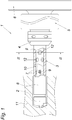
- the ejector deep drilling tool 1 shown here shows an exchangeable drill head 2, a drill pipe 3, a chuck 4, a connection piece 5 and a flange 6.
- the drill pipe 3 also serves to supply and discharge a coolant / lubricant 7 required for deep drilling, which is shown in FIG Fig. 1 is only partially shown.
- the drill pipe 3 has an outer pipe 8 and an inner pipe 9.
- An annular space 10 is formed between the outer tube 8 and an inner tube 9, via which the coolant / lubricant 7 is guided to the drill head 2.
- the annular space 10 therefore forms a flow channel for the coolant / lubricant 7, which then flows around the drill head 2 and flows back again in the inner tube 9 with chips removed from the workpiece 11.
- the ejector deep drilling tool 1 has a vibration damper 12 that engages the outer tube 8.
- this vibration damper 12 is provided in the annular space 10 between the outer and inner tubes 8, 9, which annular space 10 guides the coolant / lubricant 7 to the drill head 2.
- the vibration damper also provides support 12 also outer and inner tube 8, 9 radially from one another. In this way, the natural frequency of the ejector deep drilling tool 1 can be shifted into a frequency range that is not critical for deep drilling, which allows a comparatively low-noise deep drilling.
- this construction according to the invention also enables a more precise machining of a workpiece and thus also improves the stability of the drill head 2 / Lubricant 7 offers sufficient fastening options over the length of the annulus.
- the vibration damper 12 supports the outer and inner tubes 8, 9 against one another under elastic pretension, namely in that the height 13 of the elastic vibration damper 12 is oversized compared to the annular space height 15 of the annular space 10. This excess is in Fig. 2 on the basis of the upper flattening on the vibration damper 12, which flattening results from its deformation - in particular from a reduction in its height. This ensures that the vibration damper 12 braces the outer and inner tubes 8, 9 against each other in sections, which particularly reduces the sound output of the ejector deep drilling tool 1 during deep drilling.
- the vibration damper 12 is fastened to the inner tube 9, for which purpose the inner tube 9 forms a projection 16 with an undercut 17, which protrudes into the annular space 10.
- the height of the projection is less than the height of the annular space 15 of the annular space 10.
- the vibration damper 12 engages in the undercut 17 in a form-fitting manner.
- the form-fitting connection between the undercut 17 and the vibration damper 12 allows the vibration damper 12 to be positioned securely in the annular space 10 or holds it securely on the inner tube 9.
- the vibration damper 12 projects from the undercut 17. As also in the Fig. 2 can be seen, this projection 16 has the shape of a mushroom head. Based A vibration damper 12 designed as an O-ring 18 can be firmly attached to this shape, which increases the stability of the ejector deep drilling tool 1.
- an O-ring 18 has the advantageous property of having a slight influence on the flow of the coolant / lubricant 7, as a result of which, for example, a turbulent flow in the annular space 10 can be prevented.
- Fig. 1 to recognize that several at an angle to each other and axially offset vibration dampers 12 are provided in the annular space 10, which further improves the vibration damping.
- an offset of the vibration damper 12 by 120 degrees (central angle) has proven to be particularly noise-reducing.
- the vibration damper 12 running radially in the annular space 10 results in a web-like design.
- This structural design can, for example, easily be flowed around by coolant / lubricant 7, so that an impairment of the flow behavior is not to be expected either.
- a vibration damper 12 or more vibration dampers 12 can be provided in the annular space 10, namely between the beginning and the end of the annular space 10 serving as a flow channel for the coolant / lubricant 7.
- coolant / lubricant 7 can be introduced into the annular space 10 via the connection piece 5.
- the chuck 4 holds the drill pipe 3 on the flange 6, which has a central opening for discharging the coolant / lubricant 7 returned from the inner pipe 9 with any chips that may be carried along, which has not been shown in detail.
Landscapes
- Engineering & Computer Science (AREA)
- Mechanical Engineering (AREA)
- Drilling And Boring (AREA)
Description
- Die Erfindung betrifft ein Ejektor-Tiefbohrwerkzeug gemäß dem Oberbegriff des Anspruchs 1. Ein solches Ejektor-Tiefbohrwerkzeug ist zum Beispiel aus der
DE 12 90 026 B bekannt. - Um die Schwingungsneigung eines Ejektor-Tiefbohrwerkzeugs beim Bohren zu reduzieren, ist es aus dem Stand der Technik bekannt (
EP0090929A2 ), am Bohrrohr des Tiefbohrwerkzeugs außen einen Schwingungsdämpfer vorzusehen. Hierfür ist der Schwingungsdämpfer als Hülse ausgeführt, welcher am Bohrkopf des Bohrrohrs anliegt. Nachteilig erschweren zwischen Werkstück und Spannelemente des Tiefbohrwerkzeugs befindliche Schwingungsdämpfer die Handhabung des Werkzeugs beim Tiefenbohren - und zwar, indem beispielsweis stets auf eine Kollisionsfreiheit des Schwingungsdämpfers gegenüber dem Werkzeug geachtet werden muss. Zudem verringert solch ein Schwingungsdämpfer die erreichbar Bohrtiefe des Ejektor-Tiefbohrwerkzeugs. Außerdem bedarf es bei der konstruktiven Ausführung des Schwingungsdämpfers einer besonders exakten Ausbildung der berührenden Bereiche mit dem Tiefbohrwerkzeug, um zum einen das Führungsverhalten des Tiefbohrwerkzeugs beim Tiefbohren nicht zu beeinflussen, und zum anderen, um eine ausreichende Berührung des Tiefbohrwerkzeugs zu gewährleisten, damit Schwingungen des Tiefbohrwerkzeugs gedämpft werden können. - Zudem ist aus der
DE1290026B ist ein Tieflochbohrer bekannt, dessen Ringraum zur Zufuhr und Führung eines Kühl/Schmiermittels zum Bohrkopf durch einen Keil begrenzt wird. - Die Erfindung hat sich daher die Aufgabe gestellt, ein Ejektor-Tiefbohrwerkzeug der eingangs geschilderten Art konstruktiv derart zu verbessern, dass bei geringer Schwingungsneigung Handhabung und Genauigkeit des Ejektor-Tiefbohrwerkzeugs dennoch nicht beeinträchtigt werden. Zudem soll das Ejektor-Tiefbohrwerkzeug konstruktiv einfach ausgebildet sein.
- Die Erfindung löst die gestellte Aufgabe dadurch, dass der Schwingungsdämpfer im, zur Zufuhr und Führung des Kühl/Schmiermittels zum Bohrkopf des Ejektor-Tiefbohrwerkzeugs ausgebildeten Ringraum zwischen Außen- und Innenrohr vorgesehen ist und diese beiden gegeneinander abstützt.
- Ist der Schwingungsdämpfer im zur Zufuhr und Führung des Kühl/Schmiermittels zum Bohrkopf des Ejektor-Tiefbohrwerkzeugs ausgebildeten Ringraum zwischen Außen- und Innenrohr vorgesehen, muss durch Vermeidung schwingungsdämpfender Maßnahmen an der Außenseite des Ejektor-Tiefbohrwerkzeugs - keine Beeinträchtigung der Handhabung des Ejektor-Tiefbohrwerkzeugs in Kauf genommen werden. Der erfindungsgemäße Schwingungsdämpfer verändert nämlich nicht die Außenkontur des Bohrrohrs bzw. des Werkzeugs, wodurch wiederum eine unerwünschte Berührung von Werkstück und Werkzeug ausgeschlossen werden kann. Stützt zudem der Schwingungsdämpfer Außen- und Innenrohr gegeneinander ab, können störende oder sogar schädigende Schwingungen deutlich reduziert werden - bzw. kann deren Entstehung gänzlich vermieden werden. Dies kann insbesondere auch zu einer reduzierten Abgabe von Bohrgeräuschen während der Bearbeitung eines Werkstücks führen. Außerdem kann durch solch ein Abstützen eine Verschiebung der Eigenfrequenzen am Ejektor-Tiefbohrwerkzeug ermöglicht werden, was zur Verbesserung der Laufruhe des Ejektor-Tiefbohrwerkzeugs beitragen kann. Zudem bedarf es für diese erfindungsgemäße Lösung keine erhöhten konstruktiven Maßnahme am Ejektor-Tiefbohrwerkzeugs, weil der Schwingungsdämpfer im für die Strömung des Kühl/Schmiermittels offenen Ringraum verhältnismäßig einfach vorgesehen werden kann. Das erfindungsgemäße, besonders schwingungsarme Ejektor-Tiefbohrwerkzeug kann sich daher nicht nur durch seine einfache Handhabung sowie konstruktive Einfachheit auszeichnen, sondern auch eine hohe Genauigkeit bei der Bearbeitung eines Werkstücks zulassen.
- Stützt der Schwingungsdämpfer Außen- und Innenrohr gegeneinander unter Vorspannung ab, können damit Außen- und Innenrohr gegeneinander verspannt werden. Damit kann beispielsweise ein sich beim Tiefbohren ergebendes Spiel zwischen Schwingungsdämpfer und den beiden Rohren ausgeglichen werden und damit stets eine Schwingungskompensation für ein schwingungsarmes Ejektor-Tiefbohrwerkzeug gewährleistet werden.
- Konstruktiv einfach kann das gegenseitige Verspannen von Außen- und Innenrohr erreicht werden, wenn der Schwingungsdämpfer aufgrund seiner elastischen Verformung Außen- und Innenrohr gegeneinander verspannt. Dies kann beispielsweise durch ein entsprechendes Übermaß des Schwingungsdämpfers erreicht werden. Durch solch eine elastische Verformung ist es auch möglich, die Vorspannung zwischen Außen- und Innenrohr bei niederfrequenten Schwingungen am Ejektor-Tiefbohrwerkzeugs sicherzustellen. Die Standfestigkeit eines Ejektor-Tiefbohrwerkzeugs kann auf diese Weise weiter erhöht werden. Außerdem kann durch die elastische Verformung auch die Spannkraft festgelegt werden, was wiederum eine flexible Einstellung der Schwingungsdämpfung auf verschiedenste Parameter beim Tiefbohren erlauben kann. Somit kann sich das erfindungsgemäße Ejektor-Tiefbohrwerkzeug unter anderem auch durch vielseitige Anwendbarkeit bzw. variable Abstimmung auf die gegebenen Erfordernisse auszeichnen.
- Die schallerzeugende Schwingungsneigung des Ejektor-Tiefbohrwerkzeugs kann weiter reduziert werden, wenn der Schwingungsdämpfer Außen- und Innenrohr radial gegeneinander abstützt.
- Die Konstruktion eines Ejektor-Tiefbohrwerkzeugs kann vereinfacht werden, wenn der Schwingungsdämpfer am Außen- und/oder Innenrohr befestigt ist. Zudem kann damit sichergestellt werden, dass der Schwingungsdämpfer beim Tiefbohren an seiner vorgesehenen Stelle verbleibt - dies selbst in jenen Fällen, in denen auf das Ejektor-Tiefbohrwerkzeug vergleichsweise hohe Schwingungsbelastungen wirken und so mit erhöhten Änderungen der geometrischen Verhältnisse im Ringraum zwischen Außen- und/oder Innenrohr gerechnet werden müsste. Die Standfestigkeit des Ejektor-Tiefbohrwerkzeugs kann dadurch weiter erhöht werden.
- Vergleichsweise einfache Bedingungen zum Befestigen des Schwingungsdämpfers können sich ergeben, wenn das Außen- und/oder das Innenrohr einen in den Ringraum ragenden Vorsprung mit einem Hinterschnitt aufweist, in welchen der Schwingungsdämpfer formschlüssig zu seiner Befestigung eingreift. Zudem lässt sich auf diese Weise der Schwingungsdämpfer auch einfach montieren bzw. ist dieser für Wartungszwecke einfach austauschbar - womit sich die Handhabung des Ejektor-Tiefbohrwerkzeugs weiter erleichtern kann.
- Konstruktiv einfache Verhältnisse am Ejektor-Tiefbohrwerkzeug können sich ergeben, wenn der Vorsprung pilzkopfförmig ausgebildet ist.
- Ist der Schwingungsdämpfer als O-Ring ausgebildet, kann eine kostengünstige, aber dennoch robuste gegenseitige Abstützung von Außen- und Innenrohr sichergestellt werden.
- Entsprechend der geforderten Dämpfungswirkung am Ejektor-Tiefbohrwerkzeug können mehrere in einem Winkel zueinander und/oder axial versetzte Schwingungsdämpfer im Ringraum vorgesehen sein.
- Die schallabgebende Schwingungsneigung am Ejektor-Tiefbohrwerkzeug kann besonders gut reduziert werden, wenn mehrere um 120 Grad im Winkel zueinander versetzte Schwingungsdämpfer im Ringraum vorgesehen sind.
- Die Strömungsverhältnisse im Ringraum können unbeeinträchtigt bleiben, wenn der Schwingungsdämpfer im Ringraum mit Kühl/Schmiermittel umfließbar vorgesehen ist.
- In den Figuren ist beispielsweise der Erfindungsgegenstand anhand einer Ausführungsvariante dargestellt. Es zeigen
- Fig. 1
- eine teilweise aufgerissene Seitenansicht auf ein teilweise dargestelltes Ejektor-Tiefbohrwerkzeug und
- Fig. 2
- eine Schnittansicht nach II-II der
Fig. 1 . - Beim beispielsweise nach
Fig. 1 dargestellten Ejektor-Tiefbohrwerkzeug 1 ist ein auswechselbarer Bohrkopf 2, ein Bohrrohr 3, ein Spannfutter 4, ein Anschlussstück 5 und ein Flansch 6 zu erkennen. Das Bohrrohr 3 dient neben seiner tragenden und führenden Funktion des Bohrkopfs 2 auch zur Zu- und Abfuhr eines beim Tiefbohren benötigten Kühl/Schmiermittels 7, das inFig. 1 nur teilweise dargestellt ist. Für Letzteres weist das Bohrrohr 3 ein Außenrohr 8 und ein Innenrohr 9 auf. Zwischen Außenrohr 8 und ein Innenrohr 9 bildet sich ein Ringraum 10 aus, über welchen Kühl/Schmiermittels 7 zum Bohrkopf 2 geführt wird. Der Ringraum 10 bildet daher einen Strömungskanal für das Kühl/Schmiermittel 7 aus, das anschließend den Bohrkopf 2 umspült und im Innenrohr 9 wieder mit, vom Werkstück 11 abgetragenen Spänen zurückfließt. - Um eine vom Tiefbohren bekannte hohe Geräuschbelastung zu reduzieren, weist das Ejektor-Tiefbohrwerkzeug 1 einen am Außenrohr 8 angreifenden Schwingungsdämpfer 12 auf. Dieser Schwingungsdämpfer 12 ist erfindungsgemäß im Ringraum 10 zwischen Außen- und Innenrohr 8, 9 vorgesehen, welcher Ringraum 10 das Kühl/Schmiermittel 7 zum Bohrkopf 2 führt. Zudem stützt der Schwingungsdämpfer 12 auch Außen- und Innenrohr 8, 9 gegeneinander radial ab. Auf diese Weise kann die Eigenfrequenz des Ejektor-Tiefbohrwerkzeugs 1 in einen für das Tiefbohren unkritischen Frequenzbereich verschoben werden, was ein vergleichsweise geräuscharmes Tiefbohren zulässt. Zudem ermöglicht diese erfindungsgemäße Konstruktion auch eine präzisere Bearbeitung eines Werkstücks und verbessert damit auch die Standfestigkeit des Bohrkopfs 2. Zudem entsteht damit auch eine konstruktive Einfachheit am Ejektor-Tiefbohrwerkzeugs 1, da der Schwingungsdämpfer 12 im Ringraum 10 vorgesehen wird, der als Strömungskanal für das Kühl/Schmiermittel 7 über die Ringraumlänge ausreichende Befestigungsoptionen bietet.
- Wie in
Fig. 2 insbesondere zu erkennen, stützt der Schwingungsdämpfer 12 Außen- und Innenrohr 8, 9 gegeneinander unter elastischer Vorspannung ab, nämlich in dem der elastische Schwingungsdämpfer 12 in seiner Höhe 13 ein Übermaß 14 gegenüber der Ringraumhöhe 15 des Ringraums 10 aufweist. Dieses Übermaß ist inFig. 2 anhand der oberen Abflachung am Schwingungsdämpfer 12 zu erkennen, welche Abflachung sich durch dessen Verformung - insbesondere durch eine Verringerung seiner Höhe - ergibt. Damit wird erreicht, dass der Schwingungsdämpfer 12 Außen- und Innenrohr 8, 9 abschnittsweise gegeneinander verspannt, was die Schallabgabe des Ejektor-Tiefbohrwerkzeugs 1 beim Tiefbohren besonders verringert. - Der Schwingungsdämpfer 12 ist am Innenrohr 9 befestigt, wofür das Innenrohr 9 einen in den Ringraum 10 ragenden Vorsprung 16 mit einem Hinterschnitt 17 ausbildet. Der Vorsprung ist in der Höhe geringer als die Ringraumhöhe 15 des Ringraums 10. In den Hinterschnitt 17 greift der Schwingungsdämpfer 12 formschlüssig ein. Die formschlüssige Verbindung zwischen Hinterschnitt 17 und Schwingungsdämpfer 12 erlaubt eine sichere Positionierung des Schwingungsdämpfers 12 im Ringraum 10 bzw. hält diesen sicher am Innenrohr 9.
- Der Schwingungsdämpfers 12 steht dem Hinterschnitt 17 vor. Wie zudem in der
Fig. 2 zu erkennen, weist dieser Vorsprung 16 die Form eines Pilzkopfes auf. Anhand dieser Form lässt sich nämlich ein als O-Ring 18 ausgebildeter Schwingungsdämpfer 12 standfest befestigen, was die Standfestigkeit des Ejektor-Tiefbohrwerkzeugs 1 erhöht. - Zudem hat ein O-Ring 18 die vorteilhafte Eigenschaft, auf die Strömung des Kühl/Schmiermittels 7 einen geringen Einfluss zu nehmen, wodurch beispielsweise eine turbulente Strömung im Ringraum 10 beispielsweise verhindert werden kann.
- Des Weiteren ist in
Fig. 1 zu erkennen, das mehrere im Winkel zueinander und axial versetzte Schwingungsdämpfer 12 im Ringraum 10 vorgesehen sind, was die Schwingungsdämpfung weiter verbessert. Insbesondere hat sich ein Versatz der Schwingungsdämpfer 12 um 120 Grad (Mittelpunktswinkel) als besonders lärmreduzierend herausgestellt. - Im Allgemeinen wird erwähnt, dass durch den im Ringraum 10 radial verlaufenden Schwingungsdämpfer 12 sich eine stegartige Ausbildung ergibt. Diese konstruktive Ausbildung kann beispielsweise ohne weiteres von Kühl/Schmiermittel 7 umflossen werden, so dass auch mit einer Beeinträchtigung des Strömungsverhaltens nicht zu rechnen ist. Im Allgemeinen wird weiter erwähnt, dass ein Schwingungsdämpfer 12 oder mehrere Schwingungsdämpfer 12 im Ringraum 10, und zwar damit zwischen Anfang und Ende des als Strömungskanal für das Kühl/Schmiermittel 7 dienenden Ringraums 10, vorgesehen sein kann bzw. können.
- Bekanntermaßen kann über das Anschlussstück 5 Kühl/Schmiermittel 7 in den Ringraum 10 eingebracht werden. Das Spannfutter 4 hält das Bohrrohr 3 am Flansch 6, der eine zentrische Öffnung zum Austragen des vom Innenrohr 9 rückgeführten Kühl/Schmiermittel 7 mit eventuell mitgeführten Spänen aufweist, was nicht näher dargestellt worden ist.
Claims (11)
- Ejektor-Tiefbohrwerkzeug mit einem Bohrkopf (2), mit einem den Bohrkopf (2) tragenden Bohrrohr (3), das zur Führung von Kühl/Schmiermittel (7) ein Außenrohr (8) und ein Innenrohr (9) aufweist, die zwischen einander einen Ringraum (10) zur Zufuhr und Führung des Kühl/Schmiermittels (7) zum Bohrkopf (2) des Ejektor-Tiefbohrwerkzeugs (1) ausbilden, und mit mindestens einem am Außenrohr (8) angreifenden Schwingungsdämpfer (12), dadurch gekennzeichnet, dass der Schwingungsdämpfer (12) im, zur Zufuhr und Führung des Kühl/Schmiermittels (7) zum Bohrkopf (2) des Ejektor-Tiefbohrwerkzeugs (1) ausgebildeten Ringraum (10) zwischen Außen- und Innenrohr (8, 9) vorgesehen ist und diese beiden gegeneinander abstützt.
- Ejektor-Tiefbohrwerkzeug nach Anspruch 1, dadurch gekennzeichnet, dass der Schwingungsdämpfer (12) Außen- und Innenrohr (8, 9) gegeneinander unter Vorspannung abstützt und damit gegeneinander verspannt.
- Ejektor-Tiefbohrwerkzeug nach Anspruch 2, dadurch gekennzeichnet, dass der Schwingungsdämpfer (12) aufgrund seiner elastischen Verformung Außen- und Innenrohr (8, 9) gegeneinander verspannt.
- Ejektor-Tiefbohrwerkzeug nach Anspruch 1, 2 oder 3, dadurch gekennzeichnet, dass der Schwingungsdämpfer (12) Außen- und Innenrohr (8, 9) radial gegeneinander abstützt.
- Ejektor-Tiefbohrwerkzeug nach einem der Ansprüche 1 bis 4, dadurch gekennzeichnet, dass der Schwingungsdämpfer (12) am Außen- und/oder Innenrohr (8, 9) befestigt ist.
- Ejektor-Tiefbohrwerkzeug nach Anspruch 5, dadurch gekennzeichnet, dass das Außen- und/oder das Innenrohr (8, 9) einen in den Ringraum (10) ragenden Vorsprung (16) mit einem Hinterschnitt (17) aufweist, in welchen der Schwingungsdämpfer (12) formschlüssig zu seiner Befestigung eingreift.
- Ejektor-Tiefbohrwerkzeug nach Anspruch 6, dadurch gekennzeichnet, dass der Vorsprung (16) pilzkopfförmig ausgebildet ist.
- Ejektor-Tiefbohrwerkzeug nach einem der Ansprüche 1 bis 7, dadurch gekennzeichnet, dass der Schwingungsdämpfer (12) als O-Ring (18) ausgebildet ist.
- Ejektor-Tiefbohrwerkzeug nach einem der Ansprüche 1 bis 8, dadurch gekennzeichnet, dass mehrere in einem Winkel zueinander und/oder axial versetzte Schwingungsdämpfer (12) im Ringraum (10) vorgesehen sind.
- Ejektor-Tiefbohrwerkzeug nach Anspruch 9, dadurch gekennzeichnet, dass mehrere um 120 Grad im Winkel zueinander versetzte Schwingungsdämpfer (12) im Ringraum (10) vorgesehen sind.
- Ejektor-Tiefbohrwerkzeug nach einem der Ansprüche 1 bis 10, dadurch gekennzeichnet, dass der Schwingungsdämpfer (12) im Ringraum (10) mit Kühl/Schmiermittel (7) umfließbar vorgesehen ist.
Applications Claiming Priority (1)
| Application Number | Priority Date | Filing Date | Title |
|---|---|---|---|
| EP16165669 | 2016-04-15 |
Publications (2)
| Publication Number | Publication Date |
|---|---|
| EP3231544A1 EP3231544A1 (de) | 2017-10-18 |
| EP3231544B1 true EP3231544B1 (de) | 2020-08-26 |
Family
ID=55794861
Family Applications (1)
| Application Number | Title | Priority Date | Filing Date |
|---|---|---|---|
| EP17166719.9A Active EP3231544B1 (de) | 2016-04-15 | 2017-04-14 | Ejektor-tiefbohrwerkzeug |
Country Status (1)
| Country | Link |
|---|---|
| EP (1) | EP3231544B1 (de) |
Families Citing this family (1)
| Publication number | Priority date | Publication date | Assignee | Title |
|---|---|---|---|---|
| DE102020006093B4 (de) | 2020-10-06 | 2023-08-17 | Jürgen Flad | Tiefbohrwerkzeug doppelwandig |
Family Cites Families (8)
| Publication number | Priority date | Publication date | Assignee | Title |
|---|---|---|---|---|
| US1940220A (en) * | 1931-02-06 | 1933-12-19 | Finkl & Sons Co | Boring tool |
| DE1290026B (de) | 1962-09-14 | 1969-02-27 | Burgmueller Karl | Tieflochbohrer |
| DE2252703B2 (de) * | 1972-10-27 | 1976-01-29 | Mim, Franz, 7320 Göppingen | Tieflochbohrer |
| SU666004A2 (ru) * | 1978-01-16 | 1979-06-05 | Ленинградский Ордена Красного Знамени Механический Институт | Эжекторное сверло |
| SU891233A2 (ru) * | 1979-05-25 | 1981-12-23 | Ленинградский Ордена Красного Знамени Механический Институт | Борштанга дл обработки глубоких отверстий |
| DE3209985C2 (de) | 1982-03-18 | 1986-07-10 | Tbt Tiefbohrtechnik Gmbh Und Co Kg, 7433 Dettingen | Tiefbohrwerkzeug |
| SU1197777A1 (ru) * | 1983-09-02 | 1985-12-15 | Aleksandr A Konstantinov | Эжекторное сверло |
| JPH0215203U (de) * | 1988-07-06 | 1990-01-30 |
-
2017
- 2017-04-14 EP EP17166719.9A patent/EP3231544B1/de active Active
Non-Patent Citations (1)
| Title |
|---|
| None * |
Also Published As
| Publication number | Publication date |
|---|---|
| EP3231544A1 (de) | 2017-10-18 |
Similar Documents
| Publication | Publication Date | Title |
|---|---|---|
| DE69715673T2 (de) | Bohrstange | |
| EP2613913B1 (de) | Lanze mit strahldüse zum entgraten und/oder reinigen von werkstücken | |
| DE3105424A1 (de) | Haltevorrichtung fuer instrumente, insbesondere endodontische ultraschall-instrumente | |
| DE102010041808A1 (de) | Schaufelkranzsegment, Strömungsmaschine sowie Verfahren zu deren Herstellung | |
| DE1625452A1 (de) | Vorrichtung zum loesbaren Verbinden zweier Verbindungskoerper,insbesondere einer Scheibe mit einer Welle | |
| DE2360430A1 (de) | Schalldaempfer fuer pneumatische schlagwerkzeuge | |
| DE102015118757B3 (de) | Hydraulische Dehnspanneinrichtung | |
| DE102017116326A1 (de) | Dämpfungsvorrichtung und Werkzeughaltevorrichtung mit einer solchen Dämpfungsvorrichtung | |
| DE1450970A1 (de) | Einseitig offene Sicherungsscheibe | |
| EP1252451B1 (de) | Vorrichtung zur kupplung zweier werkzeugteile | |
| EP2338653B1 (de) | Flüssigkeitsstrahlschneidmaschine | |
| EP2377729A1 (de) | Vorrichtung zur Befestigung eines Überrollbügels oder dergleichen Anbauteiles an einem Fahrzeug | |
| DE102014014932A1 (de) | Bohrwerkzeug, insbesondere Reibahle | |
| EP3231544A1 (de) | Ejektor-tiefbohrwerkzeug | |
| DE202015105569U1 (de) | In einem Gehäuse integrierbare Vorrichtung für Schiebetüren | |
| DE102015109859A1 (de) | Überrollschutzsystem für ein Kraftfahrzeug | |
| DE102013012150A1 (de) | Satz bestehend aus einer Spannzange, einem Werkzeugträger-Einsatz sowie einer Aufnahme dafür | |
| DE10353283A1 (de) | Werkzeugaufnahme für einen Bohrhammer | |
| DE112004000454T5 (de) | Bohrmeißelanordnung, Bohrstange mit der Bohrmeißelanordnung und Bohrerspitze zum Selbstbohren von Gestein oder Ankerbolzen | |
| DE102015118769A1 (de) | Anfaswerkzeug mit Führung zur Schwingungs-Eliminierung | |
| DE102005052471A1 (de) | Radnabe mit zwischen den Löchern für Radschrauben ausgebildeten axialen Ausnehmungen | |
| DE102018118076A1 (de) | Laserdüse, Düsenaufnahme, Düsenkupplung und Werkzeugmaschine | |
| EP2801448B1 (de) | Handwerkzeugmaschine | |
| DE2841523C2 (de) | Aus Zahn und Adapter bestehender Werkzeugsatz für den Saugkopf von Saugkopfbaggern | |
| DE102016107244B4 (de) | Hydraulische Dehnspanneinrichtung |
Legal Events
| Date | Code | Title | Description |
|---|---|---|---|
| PUAI | Public reference made under article 153(3) epc to a published international application that has entered the european phase |
Free format text: ORIGINAL CODE: 0009012 |
|
| STAA | Information on the status of an ep patent application or granted ep patent |
Free format text: STATUS: THE APPLICATION HAS BEEN PUBLISHED |
|
| AK | Designated contracting states |
Kind code of ref document: A1 Designated state(s): AL AT BE BG CH CY CZ DE DK EE ES FI FR GB GR HR HU IE IS IT LI LT LU LV MC MK MT NL NO PL PT RO RS SE SI SK SM TR |
|
| AX | Request for extension of the european patent |
Extension state: BA ME |
|
| STAA | Information on the status of an ep patent application or granted ep patent |
Free format text: STATUS: REQUEST FOR EXAMINATION WAS MADE |
|
| 17P | Request for examination filed |
Effective date: 20180418 |
|
| RBV | Designated contracting states (corrected) |
Designated state(s): AL AT BE BG CH CY CZ DE DK EE ES FI FR GB GR HR HU IE IS IT LI LT LU LV MC MK MT NL NO PL PT RO RS SE SI SK SM TR |
|
| GRAP | Despatch of communication of intention to grant a patent |
Free format text: ORIGINAL CODE: EPIDOSNIGR1 |
|
| STAA | Information on the status of an ep patent application or granted ep patent |
Free format text: STATUS: GRANT OF PATENT IS INTENDED |
|
| INTG | Intention to grant announced |
Effective date: 20200306 |
|
| GRAS | Grant fee paid |
Free format text: ORIGINAL CODE: EPIDOSNIGR3 |
|
| GRAA | (expected) grant |
Free format text: ORIGINAL CODE: 0009210 |
|
| STAA | Information on the status of an ep patent application or granted ep patent |
Free format text: STATUS: THE PATENT HAS BEEN GRANTED |
|
| AK | Designated contracting states |
Kind code of ref document: B1 Designated state(s): AL AT BE BG CH CY CZ DE DK EE ES FI FR GB GR HR HU IE IS IT LI LT LU LV MC MK MT NL NO PL PT RO RS SE SI SK SM TR |
|
| REG | Reference to a national code |
Ref country code: GB Ref legal event code: FG4D Free format text: NOT ENGLISH |
|
| REG | Reference to a national code |
Ref country code: CH Ref legal event code: EP |
|
| REG | Reference to a national code |
Ref country code: DE Ref legal event code: R096 Ref document number: 502017006885 Country of ref document: DE |
|
| REG | Reference to a national code |
Ref country code: AT Ref legal event code: REF Ref document number: 1305899 Country of ref document: AT Kind code of ref document: T Effective date: 20200915 |
|
| REG | Reference to a national code |
Ref country code: IE Ref legal event code: FG4D Free format text: LANGUAGE OF EP DOCUMENT: GERMAN |
|
| REG | Reference to a national code |
Ref country code: LT Ref legal event code: MG4D |
|
| PG25 | Lapsed in a contracting state [announced via postgrant information from national office to epo] |
Ref country code: PT Free format text: LAPSE BECAUSE OF FAILURE TO SUBMIT A TRANSLATION OF THE DESCRIPTION OR TO PAY THE FEE WITHIN THE PRESCRIBED TIME-LIMIT Effective date: 20201228 Ref country code: LT Free format text: LAPSE BECAUSE OF FAILURE TO SUBMIT A TRANSLATION OF THE DESCRIPTION OR TO PAY THE FEE WITHIN THE PRESCRIBED TIME-LIMIT Effective date: 20200826 Ref country code: BG Free format text: LAPSE BECAUSE OF FAILURE TO SUBMIT A TRANSLATION OF THE DESCRIPTION OR TO PAY THE FEE WITHIN THE PRESCRIBED TIME-LIMIT Effective date: 20201126 Ref country code: SE Free format text: LAPSE BECAUSE OF FAILURE TO SUBMIT A TRANSLATION OF THE DESCRIPTION OR TO PAY THE FEE WITHIN THE PRESCRIBED TIME-LIMIT Effective date: 20200826 Ref country code: NO Free format text: LAPSE BECAUSE OF FAILURE TO SUBMIT A TRANSLATION OF THE DESCRIPTION OR TO PAY THE FEE WITHIN THE PRESCRIBED TIME-LIMIT Effective date: 20201126 Ref country code: HR Free format text: LAPSE BECAUSE OF FAILURE TO SUBMIT A TRANSLATION OF THE DESCRIPTION OR TO PAY THE FEE WITHIN THE PRESCRIBED TIME-LIMIT Effective date: 20200826 Ref country code: FI Free format text: LAPSE BECAUSE OF FAILURE TO SUBMIT A TRANSLATION OF THE DESCRIPTION OR TO PAY THE FEE WITHIN THE PRESCRIBED TIME-LIMIT Effective date: 20200826 Ref country code: GR Free format text: LAPSE BECAUSE OF FAILURE TO SUBMIT A TRANSLATION OF THE DESCRIPTION OR TO PAY THE FEE WITHIN THE PRESCRIBED TIME-LIMIT Effective date: 20201127 |
|
| REG | Reference to a national code |
Ref country code: NL Ref legal event code: MP Effective date: 20200826 |
|
| PG25 | Lapsed in a contracting state [announced via postgrant information from national office to epo] |
Ref country code: RS Free format text: LAPSE BECAUSE OF FAILURE TO SUBMIT A TRANSLATION OF THE DESCRIPTION OR TO PAY THE FEE WITHIN THE PRESCRIBED TIME-LIMIT Effective date: 20200826 Ref country code: LV Free format text: LAPSE BECAUSE OF FAILURE TO SUBMIT A TRANSLATION OF THE DESCRIPTION OR TO PAY THE FEE WITHIN THE PRESCRIBED TIME-LIMIT Effective date: 20200826 Ref country code: NL Free format text: LAPSE BECAUSE OF FAILURE TO SUBMIT A TRANSLATION OF THE DESCRIPTION OR TO PAY THE FEE WITHIN THE PRESCRIBED TIME-LIMIT Effective date: 20200826 Ref country code: PL Free format text: LAPSE BECAUSE OF FAILURE TO SUBMIT A TRANSLATION OF THE DESCRIPTION OR TO PAY THE FEE WITHIN THE PRESCRIBED TIME-LIMIT Effective date: 20200826 Ref country code: IS Free format text: LAPSE BECAUSE OF FAILURE TO SUBMIT A TRANSLATION OF THE DESCRIPTION OR TO PAY THE FEE WITHIN THE PRESCRIBED TIME-LIMIT Effective date: 20201226 |
|
| PG25 | Lapsed in a contracting state [announced via postgrant information from national office to epo] |
Ref country code: EE Free format text: LAPSE BECAUSE OF FAILURE TO SUBMIT A TRANSLATION OF THE DESCRIPTION OR TO PAY THE FEE WITHIN THE PRESCRIBED TIME-LIMIT Effective date: 20200826 Ref country code: SM Free format text: LAPSE BECAUSE OF FAILURE TO SUBMIT A TRANSLATION OF THE DESCRIPTION OR TO PAY THE FEE WITHIN THE PRESCRIBED TIME-LIMIT Effective date: 20200826 Ref country code: DK Free format text: LAPSE BECAUSE OF FAILURE TO SUBMIT A TRANSLATION OF THE DESCRIPTION OR TO PAY THE FEE WITHIN THE PRESCRIBED TIME-LIMIT Effective date: 20200826 Ref country code: CZ Free format text: LAPSE BECAUSE OF FAILURE TO SUBMIT A TRANSLATION OF THE DESCRIPTION OR TO PAY THE FEE WITHIN THE PRESCRIBED TIME-LIMIT Effective date: 20200826 Ref country code: RO Free format text: LAPSE BECAUSE OF FAILURE TO SUBMIT A TRANSLATION OF THE DESCRIPTION OR TO PAY THE FEE WITHIN THE PRESCRIBED TIME-LIMIT Effective date: 20200826 |
|
| REG | Reference to a national code |
Ref country code: DE Ref legal event code: R097 Ref document number: 502017006885 Country of ref document: DE |
|
| PG25 | Lapsed in a contracting state [announced via postgrant information from national office to epo] |
Ref country code: ES Free format text: LAPSE BECAUSE OF FAILURE TO SUBMIT A TRANSLATION OF THE DESCRIPTION OR TO PAY THE FEE WITHIN THE PRESCRIBED TIME-LIMIT Effective date: 20200826 Ref country code: AL Free format text: LAPSE BECAUSE OF FAILURE TO SUBMIT A TRANSLATION OF THE DESCRIPTION OR TO PAY THE FEE WITHIN THE PRESCRIBED TIME-LIMIT Effective date: 20200826 |
|
| PG25 | Lapsed in a contracting state [announced via postgrant information from national office to epo] |
Ref country code: SK Free format text: LAPSE BECAUSE OF FAILURE TO SUBMIT A TRANSLATION OF THE DESCRIPTION OR TO PAY THE FEE WITHIN THE PRESCRIBED TIME-LIMIT Effective date: 20200826 |
|
| PLBE | No opposition filed within time limit |
Free format text: ORIGINAL CODE: 0009261 |
|
| STAA | Information on the status of an ep patent application or granted ep patent |
Free format text: STATUS: NO OPPOSITION FILED WITHIN TIME LIMIT |
|
| PG25 | Lapsed in a contracting state [announced via postgrant information from national office to epo] |
Ref country code: IT Free format text: LAPSE BECAUSE OF FAILURE TO SUBMIT A TRANSLATION OF THE DESCRIPTION OR TO PAY THE FEE WITHIN THE PRESCRIBED TIME-LIMIT Effective date: 20200826 |
|
| 26N | No opposition filed |
Effective date: 20210527 |
|
| PG25 | Lapsed in a contracting state [announced via postgrant information from national office to epo] |
Ref country code: SI Free format text: LAPSE BECAUSE OF FAILURE TO SUBMIT A TRANSLATION OF THE DESCRIPTION OR TO PAY THE FEE WITHIN THE PRESCRIBED TIME-LIMIT Effective date: 20200826 |
|
| PG25 | Lapsed in a contracting state [announced via postgrant information from national office to epo] |
Ref country code: MC Free format text: LAPSE BECAUSE OF FAILURE TO SUBMIT A TRANSLATION OF THE DESCRIPTION OR TO PAY THE FEE WITHIN THE PRESCRIBED TIME-LIMIT Effective date: 20200826 |
|
| GBPC | Gb: european patent ceased through non-payment of renewal fee |
Effective date: 20210414 |
|
| PG25 | Lapsed in a contracting state [announced via postgrant information from national office to epo] |
Ref country code: LU Free format text: LAPSE BECAUSE OF NON-PAYMENT OF DUE FEES Effective date: 20210414 |
|
| REG | Reference to a national code |
Ref country code: BE Ref legal event code: MM Effective date: 20210430 |
|
| PG25 | Lapsed in a contracting state [announced via postgrant information from national office to epo] |
Ref country code: GB Free format text: LAPSE BECAUSE OF NON-PAYMENT OF DUE FEES Effective date: 20210414 Ref country code: FR Free format text: LAPSE BECAUSE OF NON-PAYMENT OF DUE FEES Effective date: 20210430 Ref country code: LI Free format text: LAPSE BECAUSE OF NON-PAYMENT OF DUE FEES Effective date: 20210430 Ref country code: CH Free format text: LAPSE BECAUSE OF NON-PAYMENT OF DUE FEES Effective date: 20210430 |
|
| PG25 | Lapsed in a contracting state [announced via postgrant information from national office to epo] |
Ref country code: IE Free format text: LAPSE BECAUSE OF NON-PAYMENT OF DUE FEES Effective date: 20210414 |
|
| PG25 | Lapsed in a contracting state [announced via postgrant information from national office to epo] |
Ref country code: IS Free format text: LAPSE BECAUSE OF FAILURE TO SUBMIT A TRANSLATION OF THE DESCRIPTION OR TO PAY THE FEE WITHIN THE PRESCRIBED TIME-LIMIT Effective date: 20201226 |
|
| PG25 | Lapsed in a contracting state [announced via postgrant information from national office to epo] |
Ref country code: BE Free format text: LAPSE BECAUSE OF NON-PAYMENT OF DUE FEES Effective date: 20210430 |
|
| PG25 | Lapsed in a contracting state [announced via postgrant information from national office to epo] |
Ref country code: HU Free format text: LAPSE BECAUSE OF FAILURE TO SUBMIT A TRANSLATION OF THE DESCRIPTION OR TO PAY THE FEE WITHIN THE PRESCRIBED TIME-LIMIT; INVALID AB INITIO Effective date: 20170414 |
|
| P01 | Opt-out of the competence of the unified patent court (upc) registered |
Effective date: 20230514 |
|
| PG25 | Lapsed in a contracting state [announced via postgrant information from national office to epo] |
Ref country code: CY Free format text: LAPSE BECAUSE OF FAILURE TO SUBMIT A TRANSLATION OF THE DESCRIPTION OR TO PAY THE FEE WITHIN THE PRESCRIBED TIME-LIMIT Effective date: 20200826 |
|
| PG25 | Lapsed in a contracting state [announced via postgrant information from national office to epo] |
Ref country code: MK Free format text: LAPSE BECAUSE OF FAILURE TO SUBMIT A TRANSLATION OF THE DESCRIPTION OR TO PAY THE FEE WITHIN THE PRESCRIBED TIME-LIMIT Effective date: 20200826 |
|
| PG25 | Lapsed in a contracting state [announced via postgrant information from national office to epo] |
Ref country code: MT Free format text: LAPSE BECAUSE OF FAILURE TO SUBMIT A TRANSLATION OF THE DESCRIPTION OR TO PAY THE FEE WITHIN THE PRESCRIBED TIME-LIMIT Effective date: 20200826 |
|
| PG25 | Lapsed in a contracting state [announced via postgrant information from national office to epo] |
Ref country code: TR Free format text: LAPSE BECAUSE OF FAILURE TO SUBMIT A TRANSLATION OF THE DESCRIPTION OR TO PAY THE FEE WITHIN THE PRESCRIBED TIME-LIMIT Effective date: 20200826 |
|
| PGFP | Annual fee paid to national office [announced via postgrant information from national office to epo] |
Ref country code: DE Payment date: 20260420 Year of fee payment: 10 |
|
| PGFP | Annual fee paid to national office [announced via postgrant information from national office to epo] |
Ref country code: AT Payment date: 20260420 Year of fee payment: 10 |