EP3231503B1 - Rotationsmaschine zum mischen, pumpen oder schütteln einer flüssigkeit und montageverfahren - Google Patents
Rotationsmaschine zum mischen, pumpen oder schütteln einer flüssigkeit und montageverfahren Download PDFInfo
- Publication number
- EP3231503B1 EP3231503B1 EP17160300.4A EP17160300A EP3231503B1 EP 3231503 B1 EP3231503 B1 EP 3231503B1 EP 17160300 A EP17160300 A EP 17160300A EP 3231503 B1 EP3231503 B1 EP 3231503B1
- Authority
- EP
- European Patent Office
- Prior art keywords
- leg
- rotary machine
- outer member
- accordance
- mounting
- Prior art date
- Legal status (The legal status is an assumption and is not a legal conclusion. Google has not performed a legal analysis and makes no representation as to the accuracy of the status listed.)
- Active
Links
Images



Classifications
-
- B—PERFORMING OPERATIONS; TRANSPORTING
- B01—PHYSICAL OR CHEMICAL PROCESSES OR APPARATUS IN GENERAL
- B01F—MIXING, e.g. DISSOLVING, EMULSIFYING OR DISPERSING
- B01F27/00—Mixers with rotary stirring devices in fixed receptacles; Kneaders
- B01F27/60—Mixers with rotary stirring devices in fixed receptacles; Kneaders with stirrers rotating about a horizontal or inclined axis
- B01F27/70—Mixers with rotary stirring devices in fixed receptacles; Kneaders with stirrers rotating about a horizontal or inclined axis with paddles, blades or arms
-
- F—MECHANICAL ENGINEERING; LIGHTING; HEATING; WEAPONS; BLASTING
- F04—POSITIVE - DISPLACEMENT MACHINES FOR LIQUIDS; PUMPS FOR LIQUIDS OR ELASTIC FLUIDS
- F04D—NON-POSITIVE-DISPLACEMENT PUMPS
- F04D29/00—Details, component parts, or accessories
- F04D29/60—Mounting; Assembling; Disassembling
- F04D29/64—Mounting; Assembling; Disassembling of axial pumps
- F04D29/648—Mounting; Assembling; Disassembling of axial pumps especially adapted for liquid pumps
-
- B—PERFORMING OPERATIONS; TRANSPORTING
- B01—PHYSICAL OR CHEMICAL PROCESSES OR APPARATUS IN GENERAL
- B01F—MIXING, e.g. DISSOLVING, EMULSIFYING OR DISPERSING
- B01F27/00—Mixers with rotary stirring devices in fixed receptacles; Kneaders
- B01F27/05—Stirrers
- B01F27/09—Stirrers characterised by the mounting of the stirrers with respect to the receptacle
-
- B—PERFORMING OPERATIONS; TRANSPORTING
- B01—PHYSICAL OR CHEMICAL PROCESSES OR APPARATUS IN GENERAL
- B01F—MIXING, e.g. DISSOLVING, EMULSIFYING OR DISPERSING
- B01F27/00—Mixers with rotary stirring devices in fixed receptacles; Kneaders
- B01F27/05—Stirrers
- B01F27/11—Stirrers characterised by the configuration of the stirrers
- B01F27/113—Propeller-shaped stirrers for producing an axial flow, e.g. shaped like a ship or aircraft propeller
-
- B—PERFORMING OPERATIONS; TRANSPORTING
- B01—PHYSICAL OR CHEMICAL PROCESSES OR APPARATUS IN GENERAL
- B01F—MIXING, e.g. DISSOLVING, EMULSIFYING OR DISPERSING
- B01F27/00—Mixers with rotary stirring devices in fixed receptacles; Kneaders
- B01F27/60—Mixers with rotary stirring devices in fixed receptacles; Kneaders with stirrers rotating about a horizontal or inclined axis
- B01F27/71—Mixers with rotary stirring devices in fixed receptacles; Kneaders with stirrers rotating about a horizontal or inclined axis with propellers
-
- B—PERFORMING OPERATIONS; TRANSPORTING
- B01—PHYSICAL OR CHEMICAL PROCESSES OR APPARATUS IN GENERAL
- B01F—MIXING, e.g. DISSOLVING, EMULSIFYING OR DISPERSING
- B01F33/00—Other mixers; Mixing plants; Combinations of mixers
- B01F33/86—Mixing heads comprising a driven stirrer
-
- B—PERFORMING OPERATIONS; TRANSPORTING
- B01—PHYSICAL OR CHEMICAL PROCESSES OR APPARATUS IN GENERAL
- B01F—MIXING, e.g. DISSOLVING, EMULSIFYING OR DISPERSING
- B01F35/00—Accessories for mixers; Auxiliary operations or auxiliary devices; Parts or details of general application
-
- B—PERFORMING OPERATIONS; TRANSPORTING
- B01—PHYSICAL OR CHEMICAL PROCESSES OR APPARATUS IN GENERAL
- B01F—MIXING, e.g. DISSOLVING, EMULSIFYING OR DISPERSING
- B01F35/00—Accessories for mixers; Auxiliary operations or auxiliary devices; Parts or details of general application
- B01F35/30—Driving arrangements; Transmissions; Couplings; Brakes
- B01F35/31—Couplings
-
- B—PERFORMING OPERATIONS; TRANSPORTING
- B01—PHYSICAL OR CHEMICAL PROCESSES OR APPARATUS IN GENERAL
- B01F—MIXING, e.g. DISSOLVING, EMULSIFYING OR DISPERSING
- B01F35/00—Accessories for mixers; Auxiliary operations or auxiliary devices; Parts or details of general application
- B01F35/40—Mounting or supporting mixing devices or receptacles; Clamping or holding arrangements therefor
- B01F35/41—Mounting or supporting stirrer shafts or stirrer units on receptacles
- B01F35/411—Mounting or supporting stirrer shafts or stirrer units on receptacles by supporting only one extremity of the shaft
-
- B—PERFORMING OPERATIONS; TRANSPORTING
- B01—PHYSICAL OR CHEMICAL PROCESSES OR APPARATUS IN GENERAL
- B01F—MIXING, e.g. DISSOLVING, EMULSIFYING OR DISPERSING
- B01F35/00—Accessories for mixers; Auxiliary operations or auxiliary devices; Parts or details of general application
- B01F35/40—Mounting or supporting mixing devices or receptacles; Clamping or holding arrangements therefor
- B01F35/41—Mounting or supporting stirrer shafts or stirrer units on receptacles
- B01F35/411—Mounting or supporting stirrer shafts or stirrer units on receptacles by supporting only one extremity of the shaft
- B01F35/4112—Mounting or supporting stirrer shafts or stirrer units on receptacles by supporting only one extremity of the shaft at the bottom of the receptacle, e.g. by studs
-
- B—PERFORMING OPERATIONS; TRANSPORTING
- B01—PHYSICAL OR CHEMICAL PROCESSES OR APPARATUS IN GENERAL
- B01F—MIXING, e.g. DISSOLVING, EMULSIFYING OR DISPERSING
- B01F35/00—Accessories for mixers; Auxiliary operations or auxiliary devices; Parts or details of general application
- B01F35/40—Mounting or supporting mixing devices or receptacles; Clamping or holding arrangements therefor
- B01F35/41—Mounting or supporting stirrer shafts or stirrer units on receptacles
- B01F35/411—Mounting or supporting stirrer shafts or stirrer units on receptacles by supporting only one extremity of the shaft
- B01F35/4113—Mounting or supporting stirrer shafts or stirrer units on receptacles by supporting only one extremity of the shaft at a side wall of the receptacle
-
- B—PERFORMING OPERATIONS; TRANSPORTING
- B01—PHYSICAL OR CHEMICAL PROCESSES OR APPARATUS IN GENERAL
- B01F—MIXING, e.g. DISSOLVING, EMULSIFYING OR DISPERSING
- B01F35/00—Accessories for mixers; Auxiliary operations or auxiliary devices; Parts or details of general application
- B01F35/40—Mounting or supporting mixing devices or receptacles; Clamping or holding arrangements therefor
- B01F35/41—Mounting or supporting stirrer shafts or stirrer units on receptacles
- B01F35/412—Mounting or supporting stirrer shafts or stirrer units on receptacles by supporting both extremities of the shaft
-
- F—MECHANICAL ENGINEERING; LIGHTING; HEATING; WEAPONS; BLASTING
- F04—POSITIVE - DISPLACEMENT MACHINES FOR LIQUIDS; PUMPS FOR LIQUIDS OR ELASTIC FLUIDS
- F04D—NON-POSITIVE-DISPLACEMENT PUMPS
- F04D13/00—Pumping installations or systems
- F04D13/02—Units comprising pumps and their driving means
- F04D13/06—Units comprising pumps and their driving means the pump being electrically driven
-
- F—MECHANICAL ENGINEERING; LIGHTING; HEATING; WEAPONS; BLASTING
- F04—POSITIVE - DISPLACEMENT MACHINES FOR LIQUIDS; PUMPS FOR LIQUIDS OR ELASTIC FLUIDS
- F04D—NON-POSITIVE-DISPLACEMENT PUMPS
- F04D29/00—Details, component parts, or accessories
- F04D29/007—Details, component parts, or accessories especially adapted for liquid pumps
-
- F—MECHANICAL ENGINEERING; LIGHTING; HEATING; WEAPONS; BLASTING
- F04—POSITIVE - DISPLACEMENT MACHINES FOR LIQUIDS; PUMPS FOR LIQUIDS OR ELASTIC FLUIDS
- F04D—NON-POSITIVE-DISPLACEMENT PUMPS
- F04D29/00—Details, component parts, or accessories
- F04D29/04—Shafts or bearings, or assemblies thereof
- F04D29/043—Shafts
-
- F—MECHANICAL ENGINEERING; LIGHTING; HEATING; WEAPONS; BLASTING
- F04—POSITIVE - DISPLACEMENT MACHINES FOR LIQUIDS; PUMPS FOR LIQUIDS OR ELASTIC FLUIDS
- F04D—NON-POSITIVE-DISPLACEMENT PUMPS
- F04D29/00—Details, component parts, or accessories
- F04D29/18—Rotors
- F04D29/181—Axial flow rotors
Definitions
- a rotary machine for mixing, pumping or agitating a fluid as per claim 1 comprising an impeller for acting on the fluid, a drive unit for rotating the impeller around a rotation axis, a drive shaft connecting the impeller with the drive unit, a mounting flange for fastening the rotary machine to a wall of a vessel, and a support structure for supporting the rotary machine, wherein the support structure comprises at least one leg, each leg extending in a vertical plane from a first end along a longitudinal axis to a second end, wherein each leg comprises an outer member and an inner member coaxially arranged in the outer member, and wherein the inner member is slidingly movable relative to the outer member for adjusting the length of the respective leg.
- Each leg comprises a mounting plate at the first end of the respective leg for mounting the leg to a housing part of the rotary machine, and a base plate at the second end of the respective leg for connecting the leg to a foundation or the ground.
- the mounting plate renders possible an easy detachment and an easy fixing of the respective leg to the housing part of the rotary machine.
- the respective leg may be firmly connected, for example by screws, to the foundation or to the floor.
- the rotary machine has two legs, wherein the mounting angle for each leg is between 60° and 85°, preferably between 70° and 80°.
- the method according to the invention is in particular suited when the rotary machine is an agitator, in particular an agitator for being horizontally mounted.
- agitator as an example for a rotary machine according to the invention. Although this is in practice an important embodiment of the invention it has to be understood that the invention is not restricted to such embodiments as an agitator.
- the rotary machine according to the invention may also be designed as any other type of a rotary machine for mixing, pumping or agitating fluids, wherein the rotary machine is intended for being mounted to a wall of a vessel.
- the rotary machine may also be a pump.
- the agitator 1 shown in Fig. 1 is designed as a side-mounted agitator 1 and designed for being mounted in particular horizontally to a wall of a vessel, a tank, a tower, a container or any other receptacle, i.e. the drive shaft 3 is extending horizontally in the usual orientation of use of the agitator 1.
- the invention is not restricted to side-mounted or horizontal agitators.
- the agitator 1 may also be designed for example as a top-mounted or vertical agitator, i.e. with the drive shaft extending vertically in the usual orientation of use.
- the agitator 1 is designed for an oblique mounting to the wall of a vessel, i.e. the rotation axis A or the drive shaft 3, respectively, of the mounted agitator includes an angle with the horizontal direction that is different from zero degree and different from 90 degree.
- FIG. 5 shows a schematic sketch corresponding to a plan view from the backside of the agitator 1, wherein the backside is the side facing away from the impeller 2.
- the agitator 1 is fastened to a wall 10 of a vessel 11, wherein the vessel 11 may be any type of a receptacle, e.g. a tower or a tank.
- the side-mounted agitator 1 has a mounting flange 5 (see Fig. 1 ) for fastening the agitator 1 to the wall 10 of the vessel 11.
- the mounting flange 5 surrounds the drive shaft 3 concentrically and comprises several bores for receiving screws or bolts for fastening the agitator 1 to the wall 10 in a manner which is as such known in the art.
- the agitator 1 is mounted to the wall 10, the mounting flange 5, the impeller 2 and the part of the shaft drive 3 between the mounting flange 5 and the impeller 2 are located within the vessel 11, containing the process fluid to be agitated or mixed or pumped by the impeller 2. Further details of the agitator 1 such as seals and bearings are well known to the skilled person and therefore will not be described in more detail.
- the agitator 1 In order to support the agitator 1 and to unload the mounting flange 5 from the weight especially of the drive unit 4 the agitator 1 comprises a support structure 7 extending between a housing part 8 of the agitator 1 and a foundation 12 or the floor 12.
- the foundation 12 may be the floor or the ground of the location where the agitator 1 is installed or a solid stand or baseplate which is able to bear the weight of the agitator 1 transferred to it by the support structure 7.
- the support structure 7 comprises a plurality of legs 71 - in this embodiment exactly two legs 71 - each leg extending in a vertical plane 13 ( Fig. 5 ).
- a vertical plane 13 shall be understood as a plane that is perpendicular to the earth's surface, i.e. a plane extending in the direction of gravity.
- a horizontal plane shall be understood as a plane that is parallel to the earth's surface, i.e. a plane extending perpendicular to the direction of gravity.
- 'vertical' denotes a direction that is parallel or equal to the direction of gravity
- 'horizontal' denotes a direction that is perpendicular to the direction of gravity.
- quadratic cross section of the inner members 73 and the outer members 72 is a preferred measure from the point of view of stability and procurement, it goes without saying that other cross sections perpendicular to the longitudinal axis L are also possible, for example a rectangular cross section, a circular cross section, a triangular cross section or the like.
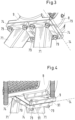
- the base plate 75 extends in a horizontal plane, i.e. parallel to the foundation 12 and preferably comprises a plurality of holes - here four holes, one in each corner - for fixing the leg 71 to the foundation 12.
- the base plate 75 may be secured to the foundation 12 by means of screws or bolts extending through the holes in the base plate 74.
- each mounting plate 74 extends in a plane which is parallel to the rotation axis A of the agitator 1. If the agitator 1 is horizontally mounted each mounting plate 74 extends in a horizontal plane 14 ( Fig. 5 ).
- the connecting part 9 may be formed integrally with the housing part 8 or it may be a separate part that is firmly connected to the housing part 8 by any appropriate means, for example by welding.
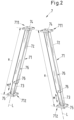
- the outer member 72 comprises at least one pre-drilled hole 76 ( Fig. 2 ) preferably extending perpendicular to the longitudinal axis L of the leg 71.
- each pre-drilled hole 76 extends through both opposing side faces of the respective outer member 72.
- the pre-drilled hole 76 is intended for receiving a securing element (not shown), for example a screw and a nut.
- the outer member 72 has a plurality of pre-drilled holes 76.
- This provides the advantage that depending on the adjusted length H of the leg 71, i.e. how much the inner member 73 has been moved out of the outer member 72 an appropriate location may be chosen for providing the perforation for the securing element.
- a plurality of pre-drilled holes 76 enables the use of more than one, preferably two, securing elements, e.g. two screws and two nuts, for making the fixation of the outer member 72 relative to the inner member 73 even more stable, safe and reliable.
- the outer member 72 has four side faces each extending in the direction of the longitudinal axis L.
- at least two different and abutting side faces of the outer member 72 are provided with at least one pre-drilled hole 76.
- two securing means e.g. screws and nuts that extend perpendicular with respect to each other.
- This provides a very stable and reliable fixation of the inner member 73 with respect to the outer member 72.
- the horizontal plane 14 in which the mounting plate 74 extends and the longitudinal axis L of the leg 71 include a mounting angle ⁇ that is different from 90 degree.
- the mounting angle ⁇ has the same value for each leg 71.
- the preferred range for the mounting angle ⁇ is from 60° to 85°. Even more preferred the mounting angle ⁇ is between 70° and 80°.
- the two legs 71 are arranged symmetrically with respect to the vertical direction V, i.e. each leg 71 includes the same angle with the vertical direction V.
- the resulting angle between the two legs 71 is between 30° and 60°.
- the resulting angle between the two legs 71 is between 20° and 40°.
- a preferred method for mounting the agitator 1 to the wall 10 of the vessel 11 comprises the following steps: the mounting flange 5 of the agitator 1 is fastened to the wall 10 of the vessel 11. If not yet done the leg 71 or the legs 71 is/are connected and fixed to the connecting part 9. The inner member 73 is slidingly moved with respect to the outer member 72. This movement can be caused by gravity only, i.e. the inner member 73 is released with respect to the outer member 72 and drops down to the foundation 12. Thus, each leg 71 is adjusted or extended to the correct length H by moving the inner member 73 of the leg 71 relative to the coaxially arranged outer member 72 of the leg 71 along the longitudinal axis L of the leg 71 until the base plate 75 of the leg 71 contacts the foundation 12. After that the inner member 73 is fixed to the outer member 72 of the respective leg 71, for example in a manner as described hereinbefore.
- the support structure 7 comprises only one leg 71.
- the leg 71 is extending in the vertical direction V, i.e. the longitudinal axis L of the leg 71 coincides with the vertical direction V.
- the mounting plate 74 is arranged centrally with respect to the connecting part 9 to provide the most effective support. If the agitator 1 is horizontally mounted the mounting plate 74 extends in the horizontal plane 14. Thus, the mounting angle ⁇ between the horizontal plane 14 in which the mounting plate 74 extends and the longitudinal axis L of the leg 71 equals 90 degree.
- the agitator 1 is designed for an oblique mounting to the wall of a vessel, i.e. the rotation axis A or the drive shaft 3, respectively, of the mounted agitator 1 includes an angle with the horizontal direction that is different from zero degree and different from 90 degree.
- the mounting plate 74 is extending in a plane that is parallel to the rotation axis A such that there is a plane contact surface between the mounting plate 74 and the connecting part 9.
- the leg 71 is again extending in the vertical direction V.
Landscapes
- Chemical & Material Sciences (AREA)
- Chemical Kinetics & Catalysis (AREA)
- Engineering & Computer Science (AREA)
- Mechanical Engineering (AREA)
- General Engineering & Computer Science (AREA)
- Aviation & Aerospace Engineering (AREA)
- Mixers Of The Rotary Stirring Type (AREA)
- Accessories For Mixers (AREA)
- Structures Of Non-Positive Displacement Pumps (AREA)
Claims (14)
- Rotationsmaschine zum Mischen, Pumpen oder Rühren eines Fluids, umfassend ein Laufrad (2) zum Einwirken auf das Fluid, eine Antriebseinheit (4) zum Drehen des Laufrads (2) um eine Rotationsachse (A), eine Antriebswelle (3), die das Laufrad (2) mit der Antriebseinheit (4) verbindet, einen Montageflansch (5) zum Befestigen der Rotationsmaschine (1) an einer Wand (10) eines Gefässes (11) und eine Stützstruktur (7) zum Stützen der Rotationsmaschine, wobei die Stützstruktur (7) mindestens ein Bein (71) umfasst, wobei sich jedes Bein (71) in einer vertikalen Ebene (13) von einem ersten Ende (711) entlang einer Längsachse (L) zu einem zweiten Ende (712) erstreckt, dadurch gekennzeichnet, dass jedes Bein (71) ein äusseres Element (72) und ein inneres Element (73) umfasst, das koaxial in dem äusseren Element (72) angeordnet ist, wobei das innere Element (73) relativ zum äusseren Element (72) gleitend bewegbar ist, um die Länge (H) des jeweiligen Beines (71) einzustellen, und wobei jedes Bein (71) eine Montageplatte (74) am ersten Ende (711) des jeweiligen Beines (71) zum Montieren des Beines (71) an einem Gehäuseteil (8) der Rotationsmaschine (1) und eine Grundplatte (75) am zweiten Ende (712) des jeweiligen Beines (71) zum Verbinden des Beines (71) mit einem Fundament (12) oder dem Boden (12) umfasst.
- Rotationsmaschine nach Anspruch 1, wobei jedes äussere Element (72) mindestens ein vorgebohrtes Loch (76) zur Aufnahme eines Sicherungselements umfasst.
- Rotationsmaschine nach einem der vorangehenden Ansprüche, wobei eine Ebene (14), in der sich die Montageplatte (74) erstreckt, und die Längsachse (L) des Beines (71) einen Montagewinkel (α) einschliessen, der für jedes Bein (71) von 90 Grad verschieden ist.
- Rotationsmaschine nach einem der vorangehenden Ansprüche, wobei jedes äussere Element (72) und jedes innere Element (73) einen rechteckigen Querschnitt, vorzugsweise einen quadratischen Querschnitt, in einem Schnitt senkrecht zur Längsachse (L) des jeweiligen Beines (71) aufweisen.
- Rotationsmaschine nach Anspruch 4, wobei das äussere Element (72) jedes Beines (71) vier Seitenflächen aufweist und wobei zwei unterschiedliche und aneinanderstossende Seitenflächen jeweils mit mindestens einem vorgebohrten Loch (76) versehen sind.
- Rotationsmaschine nach einem der vorangehenden Ansprüche mit zwei Beinen (71), wobei der Montagewinkel (α) für jedes Bein (7) zwischen 60° und 85°, vorzugsweise zwischen 70° und 80° liegt.
- Rotationsmaschine nach einem der vorangehenden Ansprüche mit einem Verbindungsteil (9), das am Gehäuseteil (8) der Rotationsmaschine fixiert ist und ausgestaltet ist, um mit jedem Bein (71) lösbar verbunden zu werden.
- Rotationsmaschine nach Anspruch 7, wobei jede Montageplatte (74) mit Hilfe von Schrauben (79) an dem Verbindungsteil (9) montierbar ist.
- Rotationsmaschine nach einem der vorangehenden Ansprüche, die als Rührwerk (1) zum Mischen oder Rühren eines Fluids ausgestaltet ist.
- Rotationsmaschine nach Anspruch 9, wobei das Rührwerk (1) für eine horizontale Montage an der Wand (10) des Gefässes (11) ausgestaltet ist.
- Verfahren zum Montieren einer Rotationsmaschine zum Mischen, Pumpen oder Rühren eines Fluids an einer Wand (10) eines Gefässes (11), umfassend die Schritte von: Befestigen eines Montageflansches (5) der Rotationsmaschine an der Wand (10) des Gefässes (11) und Montieren mindestens eines Beines (71) einer Stützstruktur (7) an einem Gehäuseteil (8) der Rotationsmaschine (1) mit einer Montageplatte (74) an einem ersten Ende (711) des jeweiligen Beines (71), gekennzeichnet durch Verlängern eines jeden Beines (71) durch Bewegen eines inneren Elements (73) des Beines (71) relativ zu einem koaxial angeordneten äusseren Element (72) des Beines (7) entlang einer Längsachse (L) des Beines (71), bis eine Grundplatte (75) des Beines (71) ein Fundament (12) berührt, und Fixieren des inneren Elements (73) an dem äusseren Element (72) des jeweiligen Beines (71).
- Verfahren nach Anspruch 11, wobei der Schritt des Fixierens des inneren Elements (73) an dem äusseren Element (72) des jeweiligen Beines (71) umfasst:
Auswählen eines aus einer Vielzahl von vorgebohrten Löchern (76) im äusseren Element (73), Verwenden des ausgewählten Lochs (76) zur Erzeugung einer Perforation, die sich durch das gesamte Bein (71) erstreckt, Einsetzen eines Sicherungselements in die Perforation zur Fixierung des inneren Elements (73) an dem äusseren Element (72). - Verfahren nach Anspruch 11 oder Anspruch 12, wobei genau zwei Beine (71) zum Stützen der Rotationsmaschine verwendet werden.
- Verfahren nach einem der Ansprüche 11 bis 13, wobei die Rotationsmaschine ein Rührwerk (1) ist, insbesondere ein Rührwerk (1) zur horizontalen Montage.
Applications Claiming Priority (1)
| Application Number | Priority Date | Filing Date | Title |
|---|---|---|---|
| EP16164640 | 2016-04-11 |
Publications (2)
| Publication Number | Publication Date |
|---|---|
| EP3231503A1 EP3231503A1 (de) | 2017-10-18 |
| EP3231503B1 true EP3231503B1 (de) | 2023-05-24 |
Family
ID=55754117
Family Applications (1)
| Application Number | Title | Priority Date | Filing Date |
|---|---|---|---|
| EP17160300.4A Active EP3231503B1 (de) | 2016-04-11 | 2017-03-10 | Rotationsmaschine zum mischen, pumpen oder schütteln einer flüssigkeit und montageverfahren |
Country Status (5)
| Country | Link |
|---|---|
| US (1) | US11339803B2 (de) |
| EP (1) | EP3231503B1 (de) |
| CN (1) | CN107281946A (de) |
| FI (1) | FI3231503T3 (de) |
| RU (1) | RU2727490C2 (de) |
Families Citing this family (1)
| Publication number | Priority date | Publication date | Assignee | Title |
|---|---|---|---|---|
| CN121018725B (zh) * | 2025-10-31 | 2026-03-24 | 景德镇水流星陶瓷文化传播有限公司 | 一种陶瓷工艺品生产用拉坯机 |
Citations (2)
| Publication number | Priority date | Publication date | Assignee | Title |
|---|---|---|---|---|
| US2096597A (en) * | 1937-01-21 | 1937-10-19 | Mixing Equipment Company Inc | Mixer drive |
| US20110284704A1 (en) * | 2010-05-18 | 2011-11-24 | Paragon Furniture LP | Extendible leg assembly and retaining system |
Family Cites Families (13)
| Publication number | Priority date | Publication date | Assignee | Title |
|---|---|---|---|---|
| US1399699A (en) * | 1920-07-01 | 1921-12-06 | Donauer Max | Liquid-agitating mechanism |
| SU10787A1 (ru) * | 1928-07-21 | 1929-07-31 | В.В. Писаренко | Машина дл смешивани красок и иных материалов |
| US2194027A (en) * | 1938-11-14 | 1940-03-19 | William J Mcdonald | Carpenter's horse |
| US3120948A (en) * | 1962-03-15 | 1964-02-11 | King Of Prussia Res And Dev Co | Variable angle mixer drive |
| DE3417204A1 (de) * | 1983-12-07 | 1985-06-20 | Gottfried Salzburg Perdolt | Ruehrgeraet |
| US4640386A (en) * | 1986-02-14 | 1987-02-03 | Hall James W | Folding utility horse |
| US4776545A (en) * | 1986-08-05 | 1988-10-11 | Ryobi Ltd. | Bench stand |
| US5118199A (en) * | 1991-04-03 | 1992-06-02 | General Signal Corporation | Side entry mixer apparatus |
| RU2083095C1 (ru) * | 1994-10-13 | 1997-07-10 | Юрий Ильич Деревцов | Маслобойка для сбивания масла из молочного сырья |
| US5954156A (en) * | 1998-08-17 | 1999-09-21 | Cooke; John E. | Adjustable saw horse |
| DE10146983A1 (de) * | 2001-09-24 | 2003-04-10 | Ksb Ag | Misch- oder Rührvorrichtung für Behälter |
| CN104147962A (zh) * | 2014-08-23 | 2014-11-19 | 济南大学 | 一种实验用搅拌机 |
| CN204525467U (zh) * | 2015-03-13 | 2015-08-05 | 山东科技大学 | 一种用于轴承外圈冲孔工艺的机械手 |
-
2017
- 2017-03-10 EP EP17160300.4A patent/EP3231503B1/de active Active
- 2017-03-10 FI FIEP17160300.4T patent/FI3231503T3/fi active
- 2017-03-14 CN CN201710150167.XA patent/CN107281946A/zh active Pending
- 2017-03-24 RU RU2017109776A patent/RU2727490C2/ru active
- 2017-03-24 US US15/468,617 patent/US11339803B2/en active Active
Patent Citations (2)
| Publication number | Priority date | Publication date | Assignee | Title |
|---|---|---|---|---|
| US2096597A (en) * | 1937-01-21 | 1937-10-19 | Mixing Equipment Company Inc | Mixer drive |
| US20110284704A1 (en) * | 2010-05-18 | 2011-11-24 | Paragon Furniture LP | Extendible leg assembly and retaining system |
Also Published As
| Publication number | Publication date |
|---|---|
| US20170292535A1 (en) | 2017-10-12 |
| CN107281946A (zh) | 2017-10-24 |
| FI3231503T3 (fi) | 2023-08-17 |
| RU2727490C2 (ru) | 2020-07-21 |
| EP3231503A1 (de) | 2017-10-18 |
| US11339803B2 (en) | 2022-05-24 |
| BR102017005318A8 (pt) | 2022-07-05 |
| RU2017109776A3 (de) | 2020-05-14 |
| BR102017005318A2 (pt) | 2017-11-21 |
| RU2017109776A (ru) | 2018-09-24 |
Similar Documents
| Publication | Publication Date | Title |
|---|---|---|
| US4981367A (en) | Portable mixing apparatus | |
| FI124092B (fi) | Menetelmä ja laitteisto yhtenäisen sekoituksen muodostamiseksi hydrometallurgisen prosessin yhteydessä | |
| JP7049793B2 (ja) | 微粒化装置 | |
| EP3231503B1 (de) | Rotationsmaschine zum mischen, pumpen oder schütteln einer flüssigkeit und montageverfahren | |
| JP5413243B2 (ja) | 攪拌装置および攪拌方法 | |
| EP2950915A1 (de) | Rührkesselreaktor | |
| US4854720A (en) | Disperser apparatus with two coaxial drive shafts | |
| KR102300428B1 (ko) | 침전물 억제 및 다중 와류를 이용한 고효율 혼합식 마그네틱 임펠러 교반기 | |
| US4984899A (en) | Agitator vessel with radially conveying agitator and with at least one baffle, as well as process for the thorough mixing of liquids with the aid of this agitator vessel | |
| Busciglio et al. | Rotary sloshing induced by impeller action in unbaffled stirred vessels | |
| US9586185B2 (en) | Mixer nozzle assembly | |
| BR102017005318B1 (pt) | Máquina rotativa para mistura, bombeamento e agitação de um fluido e método de montagem da referida máquina rotativa | |
| JP5062696B2 (ja) | 攪拌機 | |
| CN106411033A (zh) | 电机机座 | |
| CN218297370U (zh) | 一种具有精量称重的动静态称重模块 | |
| KR101894291B1 (ko) | 모형 전류고정날개에 대한 스트레인 측정용 지그 | |
| CN206422642U (zh) | 电机机座 | |
| CN214467286U (zh) | 用于静力水准仪的安装组件及用于测量高差变化的装置 | |
| CN223144936U (zh) | 一种浮选槽刮板装置 | |
| CN214305952U (zh) | 支撑地脚组件 | |
| JP2022080043A (ja) | 支援システム及び支援方法 | |
| CN108654481A (zh) | 一种粘合剂生产用搅拌装置 | |
| CN213132870U (zh) | 一种带升降水下支座的桨式搅拌机 | |
| CN215311612U (zh) | 一种双旋转涂料搅拌机 | |
| CN216756088U (zh) | 一种浆液测试搅拌机 |
Legal Events
| Date | Code | Title | Description |
|---|---|---|---|
| PUAI | Public reference made under article 153(3) epc to a published international application that has entered the european phase |
Free format text: ORIGINAL CODE: 0009012 |
|
| STAA | Information on the status of an ep patent application or granted ep patent |
Free format text: STATUS: THE APPLICATION HAS BEEN PUBLISHED |
|
| AK | Designated contracting states |
Kind code of ref document: A1 Designated state(s): AL AT BE BG CH CY CZ DE DK EE ES FI FR GB GR HR HU IE IS IT LI LT LU LV MC MK MT NL NO PL PT RO RS SE SI SK SM TR |
|
| AX | Request for extension of the european patent |
Extension state: BA ME |
|
| STAA | Information on the status of an ep patent application or granted ep patent |
Free format text: STATUS: REQUEST FOR EXAMINATION WAS MADE |
|
| 17P | Request for examination filed |
Effective date: 20180418 |
|
| RBV | Designated contracting states (corrected) |
Designated state(s): AL AT BE BG CH CY CZ DE DK EE ES FI FR GB GR HR HU IE IS IT LI LT LU LV MC MK MT NL NO PL PT RO RS SE SI SK SM TR |
|
| STAA | Information on the status of an ep patent application or granted ep patent |
Free format text: STATUS: EXAMINATION IS IN PROGRESS |
|
| 17Q | First examination report despatched |
Effective date: 20210302 |
|
| REG | Reference to a national code |
Ref country code: DE Ref legal event code: R079 Ref document number: 602017068943 Country of ref document: DE Free format text: PREVIOUS MAIN CLASS: B01F0007060000 Ipc: B01F0027710000 |
|
| RIC1 | Information provided on ipc code assigned before grant |
Ipc: B01F 35/41 20220101ALI20221125BHEP Ipc: B01F 33/00 20220101ALI20221125BHEP Ipc: B01F 27/71 20220101AFI20221125BHEP |
|
| GRAP | Despatch of communication of intention to grant a patent |
Free format text: ORIGINAL CODE: EPIDOSNIGR1 |
|
| STAA | Information on the status of an ep patent application or granted ep patent |
Free format text: STATUS: GRANT OF PATENT IS INTENDED |
|
| INTG | Intention to grant announced |
Effective date: 20230110 |
|
| GRAS | Grant fee paid |
Free format text: ORIGINAL CODE: EPIDOSNIGR3 |
|
| GRAA | (expected) grant |
Free format text: ORIGINAL CODE: 0009210 |
|
| STAA | Information on the status of an ep patent application or granted ep patent |
Free format text: STATUS: THE PATENT HAS BEEN GRANTED |
|
| AK | Designated contracting states |
Kind code of ref document: B1 Designated state(s): AL AT BE BG CH CY CZ DE DK EE ES FI FR GB GR HR HU IE IS IT LI LT LU LV MC MK MT NL NO PL PT RO RS SE SI SK SM TR |
|
| REG | Reference to a national code |
Ref country code: GB Ref legal event code: FG4D |
|
| REG | Reference to a national code |
Ref country code: CH Ref legal event code: EP |
|
| REG | Reference to a national code |
Ref country code: DE Ref legal event code: R096 Ref document number: 602017068943 Country of ref document: DE |
|
| P01 | Opt-out of the competence of the unified patent court (upc) registered |
Effective date: 20230412 |
|
| REG | Reference to a national code |
Ref country code: AT Ref legal event code: REF Ref document number: 1569184 Country of ref document: AT Kind code of ref document: T Effective date: 20230615 |
|
| REG | Reference to a national code |
Ref country code: IE Ref legal event code: FG4D |
|
| REG | Reference to a national code |
Ref country code: FI Ref legal event code: FGE |
|
| REG | Reference to a national code |
Ref country code: SE Ref legal event code: TRGR |
|
| REG | Reference to a national code |
Ref country code: LT Ref legal event code: MG9D |
|
| REG | Reference to a national code |
Ref country code: NL Ref legal event code: MP Effective date: 20230524 |
|
| PG25 | Lapsed in a contracting state [announced via postgrant information from national office to epo] |
Ref country code: PT Free format text: LAPSE BECAUSE OF FAILURE TO SUBMIT A TRANSLATION OF THE DESCRIPTION OR TO PAY THE FEE WITHIN THE PRESCRIBED TIME-LIMIT Effective date: 20230925 Ref country code: NO Free format text: LAPSE BECAUSE OF FAILURE TO SUBMIT A TRANSLATION OF THE DESCRIPTION OR TO PAY THE FEE WITHIN THE PRESCRIBED TIME-LIMIT Effective date: 20230824 Ref country code: NL Free format text: LAPSE BECAUSE OF FAILURE TO SUBMIT A TRANSLATION OF THE DESCRIPTION OR TO PAY THE FEE WITHIN THE PRESCRIBED TIME-LIMIT Effective date: 20230524 Ref country code: ES Free format text: LAPSE BECAUSE OF FAILURE TO SUBMIT A TRANSLATION OF THE DESCRIPTION OR TO PAY THE FEE WITHIN THE PRESCRIBED TIME-LIMIT Effective date: 20230524 |
|
| PG25 | Lapsed in a contracting state [announced via postgrant information from national office to epo] |
Ref country code: RS Free format text: LAPSE BECAUSE OF FAILURE TO SUBMIT A TRANSLATION OF THE DESCRIPTION OR TO PAY THE FEE WITHIN THE PRESCRIBED TIME-LIMIT Effective date: 20230524 Ref country code: PL Free format text: LAPSE BECAUSE OF FAILURE TO SUBMIT A TRANSLATION OF THE DESCRIPTION OR TO PAY THE FEE WITHIN THE PRESCRIBED TIME-LIMIT Effective date: 20230524 Ref country code: LV Free format text: LAPSE BECAUSE OF FAILURE TO SUBMIT A TRANSLATION OF THE DESCRIPTION OR TO PAY THE FEE WITHIN THE PRESCRIBED TIME-LIMIT Effective date: 20230524 Ref country code: LT Free format text: LAPSE BECAUSE OF FAILURE TO SUBMIT A TRANSLATION OF THE DESCRIPTION OR TO PAY THE FEE WITHIN THE PRESCRIBED TIME-LIMIT Effective date: 20230524 Ref country code: IS Free format text: LAPSE BECAUSE OF FAILURE TO SUBMIT A TRANSLATION OF THE DESCRIPTION OR TO PAY THE FEE WITHIN THE PRESCRIBED TIME-LIMIT Effective date: 20230924 Ref country code: HR Free format text: LAPSE BECAUSE OF FAILURE TO SUBMIT A TRANSLATION OF THE DESCRIPTION OR TO PAY THE FEE WITHIN THE PRESCRIBED TIME-LIMIT Effective date: 20230524 Ref country code: GR Free format text: LAPSE BECAUSE OF FAILURE TO SUBMIT A TRANSLATION OF THE DESCRIPTION OR TO PAY THE FEE WITHIN THE PRESCRIBED TIME-LIMIT Effective date: 20230825 |
|
| PG25 | Lapsed in a contracting state [announced via postgrant information from national office to epo] |
Ref country code: SK Free format text: LAPSE BECAUSE OF FAILURE TO SUBMIT A TRANSLATION OF THE DESCRIPTION OR TO PAY THE FEE WITHIN THE PRESCRIBED TIME-LIMIT Effective date: 20230524 |
|
| PG25 | Lapsed in a contracting state [announced via postgrant information from national office to epo] |
Ref country code: SM Free format text: LAPSE BECAUSE OF FAILURE TO SUBMIT A TRANSLATION OF THE DESCRIPTION OR TO PAY THE FEE WITHIN THE PRESCRIBED TIME-LIMIT Effective date: 20230524 Ref country code: SK Free format text: LAPSE BECAUSE OF FAILURE TO SUBMIT A TRANSLATION OF THE DESCRIPTION OR TO PAY THE FEE WITHIN THE PRESCRIBED TIME-LIMIT Effective date: 20230524 Ref country code: RO Free format text: LAPSE BECAUSE OF FAILURE TO SUBMIT A TRANSLATION OF THE DESCRIPTION OR TO PAY THE FEE WITHIN THE PRESCRIBED TIME-LIMIT Effective date: 20230524 Ref country code: EE Free format text: LAPSE BECAUSE OF FAILURE TO SUBMIT A TRANSLATION OF THE DESCRIPTION OR TO PAY THE FEE WITHIN THE PRESCRIBED TIME-LIMIT Effective date: 20230524 Ref country code: DK Free format text: LAPSE BECAUSE OF FAILURE TO SUBMIT A TRANSLATION OF THE DESCRIPTION OR TO PAY THE FEE WITHIN THE PRESCRIBED TIME-LIMIT Effective date: 20230524 Ref country code: CZ Free format text: LAPSE BECAUSE OF FAILURE TO SUBMIT A TRANSLATION OF THE DESCRIPTION OR TO PAY THE FEE WITHIN THE PRESCRIBED TIME-LIMIT Effective date: 20230524 |
|
| REG | Reference to a national code |
Ref country code: DE Ref legal event code: R097 Ref document number: 602017068943 Country of ref document: DE |
|
| PLBE | No opposition filed within time limit |
Free format text: ORIGINAL CODE: 0009261 |
|
| STAA | Information on the status of an ep patent application or granted ep patent |
Free format text: STATUS: NO OPPOSITION FILED WITHIN TIME LIMIT |
|
| 26N | No opposition filed |
Effective date: 20240227 |
|
| PG25 | Lapsed in a contracting state [announced via postgrant information from national office to epo] |
Ref country code: SI Free format text: LAPSE BECAUSE OF FAILURE TO SUBMIT A TRANSLATION OF THE DESCRIPTION OR TO PAY THE FEE WITHIN THE PRESCRIBED TIME-LIMIT Effective date: 20230524 |
|
| PG25 | Lapsed in a contracting state [announced via postgrant information from national office to epo] |
Ref country code: SI Free format text: LAPSE BECAUSE OF FAILURE TO SUBMIT A TRANSLATION OF THE DESCRIPTION OR TO PAY THE FEE WITHIN THE PRESCRIBED TIME-LIMIT Effective date: 20230524 Ref country code: IT Free format text: LAPSE BECAUSE OF FAILURE TO SUBMIT A TRANSLATION OF THE DESCRIPTION OR TO PAY THE FEE WITHIN THE PRESCRIBED TIME-LIMIT Effective date: 20230524 |
|
| REG | Reference to a national code |
Ref country code: CH Ref legal event code: PL |
|
| PG25 | Lapsed in a contracting state [announced via postgrant information from national office to epo] |
Ref country code: BG Free format text: LAPSE BECAUSE OF FAILURE TO SUBMIT A TRANSLATION OF THE DESCRIPTION OR TO PAY THE FEE WITHIN THE PRESCRIBED TIME-LIMIT Effective date: 20230524 |
|
| PG25 | Lapsed in a contracting state [announced via postgrant information from national office to epo] |
Ref country code: LU Free format text: LAPSE BECAUSE OF NON-PAYMENT OF DUE FEES Effective date: 20240310 |
|
| PG25 | Lapsed in a contracting state [announced via postgrant information from national office to epo] |
Ref country code: MC Free format text: LAPSE BECAUSE OF FAILURE TO SUBMIT A TRANSLATION OF THE DESCRIPTION OR TO PAY THE FEE WITHIN THE PRESCRIBED TIME-LIMIT Effective date: 20230524 |
|
| GBPC | Gb: european patent ceased through non-payment of renewal fee |
Effective date: 20240310 |
|
| PG25 | Lapsed in a contracting state [announced via postgrant information from national office to epo] |
Ref country code: MC Free format text: LAPSE BECAUSE OF FAILURE TO SUBMIT A TRANSLATION OF THE DESCRIPTION OR TO PAY THE FEE WITHIN THE PRESCRIBED TIME-LIMIT Effective date: 20230524 Ref country code: LU Free format text: LAPSE BECAUSE OF NON-PAYMENT OF DUE FEES Effective date: 20240310 Ref country code: BG Free format text: LAPSE BECAUSE OF FAILURE TO SUBMIT A TRANSLATION OF THE DESCRIPTION OR TO PAY THE FEE WITHIN THE PRESCRIBED TIME-LIMIT Effective date: 20230524 |
|
| PG25 | Lapsed in a contracting state [announced via postgrant information from national office to epo] |
Ref country code: GB Free format text: LAPSE BECAUSE OF NON-PAYMENT OF DUE FEES Effective date: 20240310 |
|
| PG25 | Lapsed in a contracting state [announced via postgrant information from national office to epo] |
Ref country code: IE Free format text: LAPSE BECAUSE OF NON-PAYMENT OF DUE FEES Effective date: 20240310 |
|
| PG25 | Lapsed in a contracting state [announced via postgrant information from national office to epo] |
Ref country code: IE Free format text: LAPSE BECAUSE OF NON-PAYMENT OF DUE FEES Effective date: 20240310 Ref country code: GB Free format text: LAPSE BECAUSE OF NON-PAYMENT OF DUE FEES Effective date: 20240310 Ref country code: CH Free format text: LAPSE BECAUSE OF NON-PAYMENT OF DUE FEES Effective date: 20240331 |
|
| REG | Reference to a national code |
Ref country code: AT Ref legal event code: UEP Ref document number: 1569184 Country of ref document: AT Kind code of ref document: T Effective date: 20230524 |
|
| PG25 | Lapsed in a contracting state [announced via postgrant information from national office to epo] |
Ref country code: CY Free format text: LAPSE BECAUSE OF FAILURE TO SUBMIT A TRANSLATION OF THE DESCRIPTION OR TO PAY THE FEE WITHIN THE PRESCRIBED TIME-LIMIT; INVALID AB INITIO Effective date: 20170310 |
|
| PG25 | Lapsed in a contracting state [announced via postgrant information from national office to epo] |
Ref country code: HU Free format text: LAPSE BECAUSE OF FAILURE TO SUBMIT A TRANSLATION OF THE DESCRIPTION OR TO PAY THE FEE WITHIN THE PRESCRIBED TIME-LIMIT; INVALID AB INITIO Effective date: 20170310 |
|
| PG25 | Lapsed in a contracting state [announced via postgrant information from national office to epo] |
Ref country code: TR Free format text: LAPSE BECAUSE OF FAILURE TO SUBMIT A TRANSLATION OF THE DESCRIPTION OR TO PAY THE FEE WITHIN THE PRESCRIBED TIME-LIMIT Effective date: 20230524 |
|
| PGFP | Annual fee paid to national office [announced via postgrant information from national office to epo] |
Ref country code: SE Payment date: 20260319 Year of fee payment: 10 |
|
| PGFP | Annual fee paid to national office [announced via postgrant information from national office to epo] |
Ref country code: DE Payment date: 20260319 Year of fee payment: 10 |
|
| PGFP | Annual fee paid to national office [announced via postgrant information from national office to epo] |
Ref country code: AT Payment date: 20260320 Year of fee payment: 10 |
|
| PGFP | Annual fee paid to national office [announced via postgrant information from national office to epo] |
Ref country code: BE Payment date: 20260319 Year of fee payment: 10 Ref country code: FI Payment date: 20260323 Year of fee payment: 10 |
|
| PGFP | Annual fee paid to national office [announced via postgrant information from national office to epo] |
Ref country code: FR Payment date: 20260320 Year of fee payment: 10 |