EP3230929B1 - Improvements in counting devices - Google Patents
Improvements in counting devices Download PDFInfo
- Publication number
- EP3230929B1 EP3230929B1 EP15820234.1A EP15820234A EP3230929B1 EP 3230929 B1 EP3230929 B1 EP 3230929B1 EP 15820234 A EP15820234 A EP 15820234A EP 3230929 B1 EP3230929 B1 EP 3230929B1
- Authority
- EP
- European Patent Office
- Prior art keywords
- counting wheel
- counting
- wheel
- peg
- housing
- Prior art date
- Legal status (The legal status is an assumption and is not a legal conclusion. Google has not performed a legal analysis and makes no representation as to the accuracy of the status listed.)
- Active
Links
Images


Classifications
-
- G—PHYSICS
- G06—COMPUTING OR CALCULATING; COUNTING
- G06M—COUNTING MECHANISMS; COUNTING OF OBJECTS NOT OTHERWISE PROVIDED FOR
- G06M1/00—Design features of general application
- G06M1/14—Design features of general application for transferring a condition from one stage to a higher stage
- G06M1/16—Design features of general application for transferring a condition from one stage to a higher stage self-operating, e.g. by Geneva mechanism
- G06M1/166—Design features of general application for transferring a condition from one stage to a higher stage self-operating, e.g. by Geneva mechanism with dials, pointers or similar type indicating means
-
- G—PHYSICS
- G06—COMPUTING OR CALCULATING; COUNTING
- G06M—COUNTING MECHANISMS; COUNTING OF OBJECTS NOT OTHERWISE PROVIDED FOR
- G06M1/00—Design features of general application
- G06M1/14—Design features of general application for transferring a condition from one stage to a higher stage
- G06M1/146—Design features of general application for transferring a condition from one stage to a higher stage with dials, pointers, or similar type indicating means
-
- G—PHYSICS
- G06—COMPUTING OR CALCULATING; COUNTING
- G06M—COUNTING MECHANISMS; COUNTING OF OBJECTS NOT OTHERWISE PROVIDED FOR
- G06M1/00—Design features of general application
- G06M1/14—Design features of general application for transferring a condition from one stage to a higher stage
- G06M1/16—Design features of general application for transferring a condition from one stage to a higher stage self-operating, e.g. by Geneva mechanism
-
- G—PHYSICS
- G06—COMPUTING OR CALCULATING; COUNTING
- G06M—COUNTING MECHANISMS; COUNTING OF OBJECTS NOT OTHERWISE PROVIDED FOR
- G06M1/00—Design features of general application
- G06M1/22—Design features of general application for visual indication of the result of count on counting mechanisms, e.g. by window with magnifying lens
- G06M1/24—Drums; Dials; Pointers
- G06M1/245—Dials; Pointers
-
- G—PHYSICS
- G06—COMPUTING OR CALCULATING; COUNTING
- G06M—COUNTING MECHANISMS; COUNTING OF OBJECTS NOT OTHERWISE PROVIDED FOR
- G06M1/00—Design features of general application
- G06M1/22—Design features of general application for visual indication of the result of count on counting mechanisms, e.g. by window with magnifying lens
- G06M1/26—Aligning means
-
- G—PHYSICS
- G06—COMPUTING OR CALCULATING; COUNTING
- G06M—COUNTING MECHANISMS; COUNTING OF OBJECTS NOT OTHERWISE PROVIDED FOR
- G06M1/00—Design features of general application
- G06M1/14—Design features of general application for transferring a condition from one stage to a higher stage
-
- G—PHYSICS
- G06—COMPUTING OR CALCULATING; COUNTING
- G06M—COUNTING MECHANISMS; COUNTING OF OBJECTS NOT OTHERWISE PROVIDED FOR
- G06M1/00—Design features of general application
- G06M1/22—Design features of general application for visual indication of the result of count on counting mechanisms, e.g. by window with magnifying lens
- G06M1/24—Drums; Dials; Pointers
- G06M1/248—Discs
Definitions
- This invention relates to counting devices, and in particular mechanical counting devices for medicament dispensers.
- medicament dispensers require a means to display the number of doses of medicament that remain with in the device or the number of doses that have been dispensed. This count allows a user, or a medical professional, to track usage of the device within the unit itself, to ensure that the device is being used as prescribed, and to alert as to how many doses remain to ensure that the user always has a medicament available.
- medicament dispensers include inhalers, such as dry powder inhalers, metered dose inhalers, and similar devices.
- a number of these medicament dispensers incorporate a mechanical or electronic counting device to keep count of a number of doses that remain or that have been dispensed.
- these medicament dispensers are required to be available to a user at all times, and therefore they are often transported in a pocket, handbag or otherwise.
- the dispenser, and therefore the counti ng device contained there in needs to be relatively robust to cope in these environments when subjected to adverse conditions, which might include various impacts and vibrations, and the attempted ingress of dirt and other detritus.
- adverse conditions which might include various impacts and vibrations, and the attempted ingress of dirt and other detritus.
- the counting device should not take up excessive space with in the dispenser itself.
- the number of component parts with in a dose counter can also have an effect on the likelihood of failure, or of the count being inaccurate.
- lots of component parts can also mean a more expensive device to manufacture and assemble.
- the market for medicament dispensers is greatly affected by cost, with manufacturers seeking ways to reduce unit cost wherever possible.
- a nother problem with existing devices is the size of the count that is displayed to the user of the counting device.
- the count is often viewed by a user through a small window in a housing of the counti ng device, and the size of the number that is displayed can be hard to read, particularly for those mechanical counting devices that incorporate a single wheeled device that displays a count value.
- Those counti ng devices that comprise a units wheel and a tens wheel attempt to deal with this issue. However, typically these require side-by-side wheels, or a concentric arrangement of wheels, and again to fit this within the body of a typical medicament dispenser, the wheels must be as small as possible, leaving little space in which to fit the numbers.
- US 6,405,727 discloses a dosing device with dose counter.
- the count indication is given by two wheels, whereby each wheel comprises a toothed disc portion and a smooth disc.
- the smooth disc of each wheel bears the digits, that when viewed together through a display window, can show a count for the number of doses remaining or used.
- a flexible lever acts on ratchet teeth moulded on the wheel, this lever comprising a pin feature which engages with a yoke. Whilst this device comprises a dual wheel arrangement, allowing for a count up to a value of 209, the wheels are mounted adjacent to each other, and therefore they need to be small to be of a suitable size to fit within a portable inhaler device.
- WO 2005/079727 discloses a counter for use with a medicament dispenser, where the counter comprises a fi rst count wheel and a second count wheel, both provided with drive teeth, and a kick wheel that drives the second count wheel.
- the first count wheel incorporates a fixed index tooth arranged for intermittent meshi ng with the kick teeth of the kick wheel such that rotary motion of the kick wheel results from rotary motion of the first count wheel only when the intermittent meshing occurs.
- the second count wheel in one embodi ment is contained with in the first count wheel that comprises a ring. This arrangement allows the numbers displayed on each wheel to be easier to read when the count wheels are of a size suitable for a medicament dispenser.
- this counter requires a pair of count wheels, both with drive teeth, and a kick wheel and input wheel that have corresponding teeth. It is conceivable that such an arrangement could display an inaccurate count if subjected to impacts and vibrations.
- WO 2007/077450 discloses a dose counter for a medicament delivery device which comprises a rotatable indicator dial and an index mechanism for incrementally rotating the indicator dial when the medicament is dispensed.
- the index mechanism comprises an index element and a locking element that is moveable from a first position in which it locks rotation of the indicator dial to a second unlocked position in which it allows rotation of the indicator dial when the index element engages the indicator dial.
- the dose counter comprises a further indicator dial.
- the dose counter includes a blanking element to blank the indicator dials and/or a viewing window when all of the doses have been dispensed.
- Y et another aspect relates to the use of a modified escapement mechanism to convert the linear actuation of the device in rotary motion of the dose counter dial.
- Preferred embodiments of the present invention aim to provide a counting device with a count display that is easy to read, where the numbers are clear, that is space-efficient, that keeps part count to a minimum and therefore is cost-effective to manufacture, whilst also providing means to ensure that the count that is displayed is accurate.
- a counting device for counting mechanical inputs as defined in the appended claim 1. Further optional features are recited in the associated dependent claims.
- a counting device for counting mechanical inputs comprising:
- a counting device for counting mechanical inputs comprising:
- the mechanical communication between the first counting wheel and the second counting wheel may be direct.
- Advantages of such an arrangement include that the counting device is simplified because additional features such as slave wheels are avoided. This can reduce the part count, size, and tolerance chain length of the counting device and can improve accuracy, alignment of indicia, and reliability.
- the counting device may comprise a rotational locking mechanism which is configured to prevent rotation of the second counting wheel.
- the rotational locking mechanism is also referred to herein as a rotating locking mechanism. It should be understood that this locking mechanism prevents rotational movement.
- the first counting wheel may engage with the second counting wheel to activate the rotating locking mechanism; for example, the first counting wheel may comprise a cam track or a rail which activates the rotating locking mechanism.
- the rotational locking mechanism provides the counting device with a rigid physical feature that prevents rotational movement of the second counting wheel when engaged, which substantially avoids the risk of a miscount due to the device being dropped or shaken.
- this rotational locking mechanism can reduce the force required to index when the rotational locking mechanism is disengaged, and allows the counting device to count bi-directionally, which may be advantageous, for example during assembly, or in certain use-cases.
- the rotational locking mechanism may comprise a second counting wheel formation configured to engage with the first counting wheel, the housing or a lock.
- the rotational locking mechanism may be activated by the first counti ng wheel moving the second counting wheel from a configuration where it can rotate to a configuration where it cannot rotate.
- the rotational locking mechanism may comprise a first counting wheel formation to engage the second counting wheel formation such that it cannot rotate;
- the first counting wheel formation may be a first counting wheel peg on the surface of the first counting wheel; for example, the first counting wheel peg may be at the hub of the first counting wheel.
- the rotating locking mechanism may comprise a second counting wheel formation which is a projecting peg which is configured to engage with a first counting wheel rail.
- the rotational locking mechanism may comprise a lock to engage with the second counting wheel such that it cannot rotate wherein the lock is activated by the first counting wheel; for example, the lock may be a sliding lock comprising a lock peg which engages with a first counting wheel formation to activate the lock.
- the first counting wheel formation may be a rail.
- the sliding lock may be mounted on a housing guide.
- the first counting wheel and the second counting wheel may not be coaxial when the locking mechanism is activated.
- one or both counting wheels may have a thin edge (for example having a thickness of from 10 to 400 ⁇ m for example from 40 to 200 ⁇ m or less).
- one or both counting wheels may comprise a thin annular ring.
- the annular ring may be supported by a circumferential lip on the counting ring.
- the circumferential lip has a height sufficient for a counting wheel volume to be formed which is suitable for receiving the other counting wheel such that the counting device may be a compact counting device having interleaved counting wheels.
- counting indicia are marked on the thin annular ring. This arrangement can provide a display that is almost as clear as using transparent effects, but without requiring transparent materials.
- the thin part is at least in part opaque, it can obscure mechanical features in the locally thicker regions that would otherwise visually disrupt a display surface, allowing mechanisms and display surfaces to overlap without compromising the clarity of the display.
- the range and type of features achievable in a wheel or any other part is typically greater if the part is an assembly of other parts.
- forming undercuts in injection mouldings can be very difficult or impossible, but these undercuts are required in some of the embodiments herein in order to further reduce the size of the counti ng device.
- the counting device may comprise a housing.
- the housing comprises a location mechanism configured to substantially prevent non-rotational movement of the second counting wheel, relative to the housing.
- the location mechanism comprises a housing formation configured to engage the second counting wheel.
- the housing formation comprises a housing slot or housing hole and the second counting wheel comprises at least one second counting wheel peg configured to engage with the housing slot or housing hole, or the housing formation comprises a housing peg and the second counting wheel comprises a hub which is configured to receive the housing peg.
- the first counting wheel formation comprises a first counting wheel peg on the surface of the first counti ng wheel; preferably the first counting wheel peg is at the hub of the first counting wheel.
- the formation on the second counting wheel is a projecting peg and wherein the first counting wheel formation is a rail.
- the lock is a movable lock comprising a lock peg which engages with a first counting wheel formation; preferably the first counting wheel formation is a rail.
- the movable lock is mounted on a housing guide.
- the mechanical communication comprises a release mechanism for releasing the locking mechanism.
- the release mechanism changes the configuration of the first counting wheel and second counting wheel from a first configuration to a second configuration.
- the release mechanism comprises a first counting wheel cam and a second counting wheel formation.
- the release mechanism comprises a first counting wheel rail gap and at least one second counting wheel formation or a sliding lock peg.
- the rotation mechanism comprises a first counting wheel formation configured to engage with at least one second counting wheel formation.
- the first counti ng wheel and the second counting wheel each comprise a circumferential array of counting indicia.
- the first counti ng wheel incorporates a circumferential array of unit count indicia and the second counting wheel incorporates a circumferential array of tens count indicia, and the first counting wheel is at least in part overlapping the second counting wheel, whereby for every input a unit count indicia is aligned with a tens count indicia that represents the number of inputs.
- the transparent portion of the second counting wheel is where the second counting wheel is in an overlapping relationship with the first counting wheel.
- the units indicia and the tens indicia are configured such that a particular combination of units indicia and tens indicia is displayed, wherein the first counting wheel or the second counti ng wheel incorporates at least one window.
- the housing incorporates at least one window for viewing any count indicia on the first counting wheel and the second counting wheel.
- the first counting wheel comprises an opaque portion and/or the second counting wheel comprises an opaque portion, whereby, in use, the first counting wheel opaque portion and/or second counti ng wheel opaque portion is visible through the window.
- a counting device comprises a housing with at least one housing peg projecting from its surface and a housing slot;
- the second counting wheel is movable between a first configuration at the inner end of the housing slot where the location mechanism and rotational locking mechanism are engaged, and a second configuration at the other end of the housing slot where the rotational locking mechanism is released.
- a release mechanism is configured to move the second counting wheel from the first configuration to the second configuration.
- the first counting wheel comprises a transparent disc that at least in part overlaps the second counting wheel such that the indicia of the second counting wheel is visible therethrough.
- a counting device which comprises a housing with at least one housing peg projecting from its surface and a housing slot within its surface;
- the second counting wheel is movable between a first configuration at the inner end of the housing slot where the location locking mechanism and rotational locking mechanism are engaged, and a second configuration at the other end of the housing slot where the rotational locking mechanism is released.
- the release mechanism is configured to move the second counting wheel from the first configuration to the second configuration.
- the first counti ng wheel comprises a transparent disk that at least in part overlaps the second counting wheel such that at least a portion of the second counting wheel is visible therethrough.
- a counting device which comprises a housing with a housing slot
- the second counting wheel is movable between a first configuration at the inner end of the housing slot where the location locking mechanism and rotational locking mechanism are engaged, and a second configuration at the other end of the housing slot where the rotational locking mechanism is released.
- the release mechanism is configured to move the second counting wheel from the first configuration to the second configuration.
- the second counting wheel comprises a transparent disc that at least in part overlaps the first counting wheel such that the indicia of the first counting wheel is visible there through.
- a counting device which comprises a housing with at least one housing peg and at least one housing guide;
- a counting device which comprises a housing with at least one housing peg;
- the second counting wheel may be configured to lock after a predetermined number of rotations such that the release mechanism cannot release the second counting wheel.
- a medicament dispenser incorporating the counting device as herein before described.
- a carrying case for a medicament dispenser incorporating the counting device is also described.
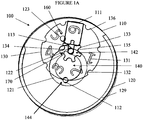
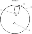
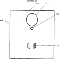
- FIGS 1A , 1B , 1C and 1D show a counting device 100 having a housing 110, a first counting wheel 120, a second counting wheel 130, a locking mechanism 140, a release mechanism 170 and a second counting wheel rotation mechanism 160.
- Housing 110 has a disk shape. On the upper surface of housing 110, a housing window 111 is formed. Housing 110 has a housing peg 112 and a housing slot 113.
- First counting wheel 120 has a first counting wheel indexing peg 123 on its surface.
- first counting wheel lip 129 which supports transparent first counting wheel indicia ring 124, on which numerals are marked clockwise from 0 to 9.
- the first counting wheel indicia ring 124 is transparent because it overlays the second counti ng wheel 130.
- the fi rst counting wheel lip 129 has a height sufficient for a volume to be formed between first counting wheel indiciaring 124 and first counting wheel 120 which is big enough to accommodate the second counting wheel 130.
- the approximate height of each numeral is about 3.5mm.
- Formed in the surface of the first counting wheel 120 there is a substantially circular first counti ng wheel cam track 121.
- the first counting wheel cam track 121 forms a first counting wheel cam 122.
- Second counting wheel 130 has a second counting wheel disk 136 and second counting wheel gear 133.
- the second counting wheel disk 136 forms seven equally spaced indentations 132 on its circumference.
- second counting wheel transparent disk 136 second counting wheel numerals 131 are marked clockwise from 1 to 6 between indentations. The approximate height of each numeral 131 is about 3.5mm.
- no numeral is marked on the seventh space between indentations 132.
- the second counting wheel gear 133 has a second counting wheel gear peg 134 extending through it.
- the second counting wheel gear 133 has second counting wheel gear indentations 135.
- the second counting wheel peg 134 forms an axle on which the second counting wheel 130 rotates.
- the second counting wheel transparent disk 136 forms a different number of indentations 132, for example from 5 to 10 indentations.
- the indentations 132 formed by second counting wheel transparent disk 136 and corresponding second counting wheel gear i ndentati ons 135 formed by second counting wheel gear 133 may be inequally spaced such that they are distributed at different angular positions around the second counti ng wheel transparent disk 136 and second counti ng wheel gear 133, respectively.
- Variable spacing of the indentations 132 could be beneficial in certain circumstances for example to accommodate a different size (for example height or width) of a corresponding numeral 131.
- each indentation 132 may be a projecting formation such as a tooth.
- second counting wheel gear peg 134 slots into housing slot 113 on one side of the second counting wheel 130 and slots into first counting wheel cam track 121 on the other side of the second counting wheel 130 such that the second counting wheel transparent disk 136 overlaps the first counting wheel 120.
- the second counting wheel disk 136 is transparent, the numerals 124 of the first counting wheel 120 arranged beneath the second counting wheel 130 are visible through housing window 111.
- the orientation of the second counting wheel 130 is locked by locking mechanism 140.
- the orientation of the second counting wheel 130 may be changed by rotation mechanism 160.
- the second counting wheel 130 is moved from its first configuration to its second configuration by release mechanism 170 which comprises the first counting wheel cam 122 and second counting wheel gear peg 134.
- the locking mechanism 140 comprises a location mechanism 142 and a rotating locking mechanism 144.
- the location mechanism 142 restricts movement of the second counting wheel 130 relative to the housing 110 to movement along housing slot 113.
- the location mechanism 142 is formed by the second counting wheel gear peg 134 engaging the housi ng slot 113.
- the rotati ng locking mechanism 144 prevents the second counting wheel 130 from rotating.
- the rotating locking mechanism 144 is formed by a second counting wheel indentation 132 engaging housing peg 112.
- the rotating locking mechanism 144 is released by release mechanism 170.
- the rotation mechanism 160 is formed by a second counting wheel gear indentation 135 engaging first counting wheel indexing peg 123 such that rotation of first counting wheel 120 causes si multaneous rotation of second counting wheel 130.
- first counting wheel cam 122 releases second counting wheel gear peg 134 such that second counting wheel 130 moves back to its first configuration where housing peg 112 engages the next second counting wheel indentation 132 such that the second counting wheel 130 is locked in configuration by rotating locking mechanism 144.
- the counting device 100 is configured to count downwards from a number of counts which is at most 69 such that the counting device 100 can be used as a remaining dose counting device in a medicament dispenser, for example. If the numerals are marked anti-clockwise on the first counting wheel 120 and second counting wheel 130, the counting device 100 could be used to count upwards to a maximum of 69. It will be understood by a person of skill in the art that the number from or to which the counting device 100 counts down or up, respectively, may be varied by changing the number of indentations 132 formed by second counting wheel transparent disk 136 and corresponding second counting wheel gear indentations 135 formed by second counting wheel gear 133.
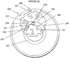
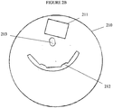
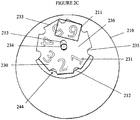
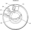
- FIGS 2A , 2B , 2C and 2D show a counting device 200 having a housi ng 210, a first counting wheel 220, a second counting wheel 230, a locking mechanism 240, a release mechanism 270 and a second counting wheel rotation mechanism 260.
- Housing 210 has a disk shape. On the upper surface of housing 210, a housing window 211 is formed. Housing 210 has a housing peg 212 and a housing slot 213.
- First counting wheel 220 has a first counting wheel indexing peg 223 on its surface at the circumference of first counting wheel 220.
- first counting wheel lip 229 which supports transparent first counting wheel indicia ring 224 on which numerals are marked clockwise from 0 to 9.
- the first counting wheel indicia ring 224 is transparent because it overlays the second counti ng wheel 230.
- the first counting wheel lip 229 has a height sufficient for a volume to be formed between first counting wheel indicia ring 224 and first counting wheel 220 sufficient to accommodate the second counting wheel 230.
- the approximate height of each numeral 224 is about 3.5mm.
- Formed in the surface of the first counting wheel 220 there is a substantially circular first counting wheel cam track 221.
- the fi rst counting wheel cam track 221 forms a first counting wheel cam 222.
- Second counting wheel 230 has an inner disk 236 which bears an outer second counting wheel gear 233.
- the second counting wheel gear 233 is toothed in that it forms seven equally spaced second counting wheel gear indentations 235 on its circumference.
- second counting wheel numerals 231 are marked clockwise from 1 to 6 between indentations 235. The approximate height of each numeral 231 is about 3.5mm.
- no numeral is marked on the seventh space between indentations 235.
- the second counting wheel 230 has a second counting wheel gear peg 234 extending through it.
- the second counting wheel gear peg 234 forms an axle on which the second counting wheel 230 rotates.
- the second counting wheel gear 233 forms a different number of indentations 235, for example from 5 to 10 indentations.
- the indentations 235 formed by second counting wheel gear 233 may be inequally spaced such that they are distributed at different angular positions around second counting wheel gear 233. Variable spacing of the indentations 235 could be beneficial in certain circumstances for example to accommodate a different size (for example height or width) of a correspondi ng numeral 231.
- each indentation 235 may be a projecting formation such as a tooth.
- the space between indentations 235 where no numeral 231 is marked may be coloured. A coloured tint on the space with no numeral is useful where the counting device 200 is used to count remaining items in a dispenser as it highlights the proximity of the count to zero.
- second counting wheel gear peg 234 slots into housing slot 213 on one side of the second counti ng wheel 230 and slots into fi rst counti ng wheel cam track 221 on the other side of the second counting wheel 230 such that the second counting wheel transparent disk 236 overlaps the first counting wheel 220.
- the numerals 224 of the first counting wheel 220 arranged beneath the second counting wheel 230 are visible through housing window 211.
- the orientation of the second counting wheel 230 is locked by locking mechanism 240.
- the orientation of the second counting wheel 230 may be changed by rotation mechanism 260.
- the second counti ng wheel 230 is moved from its first configuration to its second configuration by release mechanism 270 which comprises the first counting wheel cam 222 and second counting wheel peg 234.
- the locking mechanism 240 comprises a location mechanism 242 and a rotating locking mechanism 244.
- the location mechanism 242 restricts movement of the second counting wheel 230 relative to the housing 210 to movement along housing slot 213.
- the location mechanism 242 is formed by the second counting wheel gear peg 234 engaging the housing slot 213.
- the rotating locking mechanism 244 prevents the second counting wheel 230 from rotating.
- the rotating locking mechanism 244 is formed by a second counting wheel gear indentation 235 engaging housing peg 212.
- the rotating locking mechanism 244 is released by release mechanism 270.
- the rotation mechanism 260 is formed by a second counting wheel indentation 235 engaging first counting wheel indexing peg 223 such that rotation of first counting wheel 220 causes simultaneous rotation of second counting wheel 230.
- first counti ng wheel cam 222 releases second counting wheel peg 234 such that second counting wheel 230 moves back to its first configuration where housing peg 212 engages the next second counting wheel indentation 235 such that the second counting wheel 230 is locked in configuration by rotating locking mechanism 244.
- the counti ng device 200 is configured to count downwards from a number of counts which is at most 69 such that the counting device 200 can be used as a remaining dose counting device in a medicament dispenser, for example. If the numerals are marked anti-clockwise on the first counting wheel 220 and second counting wheel 230, the counting device 200 could be used to count upwards to a maxi mum of 69. It will be understood by a person of skill in the art that the number from or to which the counting device 200 counts down or up, respectively, may be varied by changing the number of indentations 232 formed by second counting wheel transparent disk 236 and corresponding second counting wheel gear indentations 235 formed by second counting wheel gear 233.
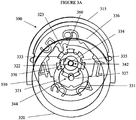
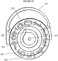
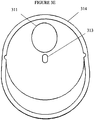
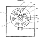
- FIGS 3A , 3B , 3C , 3D and 3E show a compact counting device 300 according to the invention having a housing 310, a first counting wheel 320, a second counting wheel 330, a locking mechanism 340, a release mechanism 370 and a second counting wheel rotation mechanism 360.
- Housing 310 has an oval shape which is formed from a housing back 315 and a housing cover 314. On the surface of housing cover 314, a housing window 311 is formed.
- Housing back 315 has a housing peg 312.
- a housing slot 313 is provided.
- First counting wheel 320 has a first counting wheel indexing peg 323 on its surface at the circumference of first counting wheel 320.
- the circumference of first counting wheel 320 forms a lip 329 which supports first counting wheel indicia ring 324, on which indicia in the form of numerals are marked clockwise from 0 to 9.
- the first counting wheel indiciaring 324 is thin, having a thickness of about 150 ⁇ m and is arranged at the periphery of the first counti ng wheel 320.
- the first counti ng wheel lip 329 has a height sufficient for a volume to be formed between first counting wheel indicia ring 324 and first counting wheel 320 which is sufficient to accommodate the second counting wheel 330.
- each numeral on indicia ring 324 is about 3.5mm.
- the first counting wheel cam track 321 forms a first counting wheel cam 322.
- Second counting wheel 330 has an inner second counting wheel gear 333 which bears a transparent second counting wheel indicia ring 336.
- the second counting wheel indiciaring 336 is transparent because it overlays the first counti ng wheel indiciaring 324.
- the second counti ng wheel indicia ring 336 is thin, having a thickness of about 150 ⁇ m and is arranged at the periphery of the second counti ng wheel 330.
- the inner second counti ng wheel gear 333 is placed on top of the first counting wheel 330 but below the first counti ng wheel indiciaring 324.
- the second counti ng wheel gear 333 is toothed in that it forms seven equally spaced second counting wheel gear indentations 335 on its circumference.
- second counting wheel indicia 331 are marked in the form of numerals clockwise from 1 to 6 between indentations 335.
- the approximate height of each numeral 331 is about 3.5mm.
- no numeral is marked on the seventh space between indentations 335.
- the second counting wheel 330 has a second counting wheel gear peg 334 extending through it.
- the second counting wheel gear peg 334 forms an axle on which the second counting wheel 330 rotates.
- the second counting wheel gear 333 forms a different number of indentations 335, for example from 5 to 10 indentations.
- the indentations 335 formed by second counting wheel gear 333 may be inequally spaced such that they are distributed at different angular positions around second counting wheel gear 333. Variable spacing of the indentations 335 could be beneficial in certain circumstances for example to accommodate a different size (for example height or width) of a corresponding numeral 331.
- each indentation 335 may be a projecting formation such as a tooth.
- the space between indentations 335 where no numeral is marked may be coloured. A coloured tint on the space with no numeral is useful where the counting device 300 is used to count remaining items in a dispenser as it highlights the proximity of the count to zero.
- second counting wheel gear peg 334 slots into housing slot 313 on the inner side of the housi ng cover 314 and slots into first counti ng wheel cam track 321 on the other side of the second counting wheel 330 such that the second counting wheel transparent disk 336 overlaps the first counti ng wheel 320.
- the numerals 324 of the first counting wheel 320 arranged beneath the second counting wheel 330 are visible through housi ng wi ndow 311.
- the orientation of the second counting wheel 330 is locked by locking mechanism 340.
- the orientation of the second counting wheel 330 may be changed by rotation mechanism 360.
- the second counti ng wheel 330 is moved from its first configuration to its second configuration by release mechanism 370 which comprises the first counti ng wheel cam 322 and second counti ng wheel gear peg 334.
- the locking mechanism 340 comprises a location mechanism 342 and a rotating locking mechanism 344.
- the location mechanism 342 restricts movement of the second counting wheel 330 relative to the housi ng 310 to movement along housi ng slot 313.
- the location mechanism 342 is formed by the second counting wheel gear peg 334 engaging the housi ng slot 313.
- the rotati ng locking mechanism 344 prevents the second counti ng wheel 330 from rotati ng.
- the rotati ng locking mechanism 344 is formed by a second counting wheel gear indentation 335 engaging first counting wheel hub 327.
- the rotating locking mechanism 344 is released by release mechanism 370.
- the rotation mechanism 360 is formed by a second counting wheel gear indentation 335 engaging first counting wheel indexing peg 323 such that rotation of first counting wheel 320 causes simultaneous rotation of second counting wheel 330.
- first counti ng wheel cam 322 releases second counting wheel peg 334 such that second counting wheel 330 moves back to its first configuration where first counting wheel hub 327 engages the next second counti ng wheel gear indentation 335 such that the second counting wheel 330 is locked in configuration by rotating locking mechanism 344.
- the counti ng device 300 is configured to count downwards from a number of counts which is at most 69 such that the counting device 300 can be used as a remaining dose counting device in a medicament dispenser, for example. If the numerals are marked anti-clockwise on the first counting wheel 320 and second counting wheel 330, the counting device 300 could be used to count upwards to a maxi mum of 69. It will be understood by a person of skill in the art that the number from or to which the counting device 300 counts down or up, respectively, may be varied by changing the number of indentations 332 formed by second counting wheel transparent disk 336 and corresponding second counting wheel gear indentations 335 formed by second counting wheel gear 333.
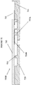
- FIGS 4A , 4B , 4C , 4D and 4E show a counti ng device 400 having a housi ng 410, a first counting wheel 420, a second counting wheel 430, a locking mechanism 440, a sliding lock 450, a release mechanism 470 and a second counting wheel rotation mechanism 460.
- Housing 410 has a rectangular shape which is formed from a housing back (not shown) and a housing cover 414. On the surface of the housing cover 414, a housing window 411 is formed. On an inner surface of housing cover 414, a housing peg 412 and parallel housing guides 416 are provided.
- First counting wheel 420 forms a circumferential inner rail 425 and a circumferential outer rail 428.
- a first counting wheel indexing peg 423 is formed on the circumferential outer rail 428.
- fi rst counti ng wheel 420 fi rst counti ng wheel numerals 424 are marked clockwise from 0 to 9. The approximate height of each numeral 424 is about 3.5mm.
- the first counting wheel rai I 425 forms a first counting wheel rail gap 426.
- the first counting wheel indexing peg 423 is positioned in the gap between numerals 9 and 0 and the first counti ng wheel rail gap 426 is opposite the fi rst counti ng wheel indexing peg 423 such that it is in the gap between numerals 4 and 5.
- Second counting wheel 430 has a transparent disk 436 which bears an inner second counting wheel gear 433 having a second counting wheel gear hub 438.
- the second counting wheel gear 433 has seven second counti ng wheel gear teeth 439 which form seven equally spaced second counti ng wheel gear indentations 435.
- second counting wheel numerals 431 are marked clockwise from 1 to 6 between indentations 435. The approximate height of each numeral 431 is about 3.5mm. On the seventh space between indentations 435, no numeral is marked.
- Sliding lock 450 has a lock body 452 forming a lock cam451 and a lock peg 453.
- second counting wheel gear hub 438 is mounted on housing peg 412 on the inner side of the housi ng cover 414 such that the second counti ng wheel 430 overlaps the first counting wheel 420.
- the second counting wheel disk 436 is transparent, the numerals 424 of the first counti ng wheel 420 arranged beneath the second counti ng wheel 430 are visible through housi ng window 411.
- the second counti ng wheel 430 is locked by locking mechanism 440 such that it cannot rotate.
- the locking mechanism 440 comprises a location mechanism 442 and a rotating locking mechanism 444.
- the location mechanism 442 locks the location of the second counting wheel 430 relative to the housing 410.
- the location mechanism 442 is formed by the second counting wheel gear hub 438 engaging the housing peg 412.
- the rotating locking mechanism 444 prevents the second counting wheel 430 from rotating.
- the rotating locking mechanism 444 is formed by second counting wheel gear teeth 439 bearing against first counting wheel outer rail 428 and second counting wheel gear indentation 435 bearing against lock cam 451.
- Lock peg 453 bears against first counting wheel inner rail 425 such that the sliding lock 450 and so the second counting wheel 430 are in a locked configuration.
- the second counting wheel 430 is unlocked such it be rotated by the rotation mechanism 460.
- the rotating locking mechanism 444 is released by release mechanism 470.
- Release mechanism 470 comprises lock peg 453 and first counting wheel inner rail gap 426.
- the rotation mechanism 460 is formed by second counting wheel gear indentation 435 engaging first counti ng wheel indexing peg 423.
- the operation of the rotation mechanism 460 pushes second counting wheel gear 433 such that a second counting wheel gear tooth 439 bears against lock cam 451. This forces lock body 452 between housing guides 416 such that lock peg 453 moves into first counting wheel inner rail gap 426 and the rotati ng locking mechanism 444 is unlocked by release mechanism 470.
- the second counti ng wheel 430 is free to rotate by one second counting wheel gear indentation 435 such that a different second counting wheel numeral 431 is shown through housing window 411.
- the positions of the first and second counting wheels 420,430 return to the fi rst configuration and the rotating locking mechanism 444 re-engages.
- the counting device 400 is configured to count downwards from a number of counts which is at most 69 such that the counting device 400 can be used as a remaining dose counting device in a medicament dispenser, for example. If the numerals are marked anti-clockwise on the first counting wheel 420 and second counting wheel 430, the counting device 400 could be used to count upwards to a maxi mum of 69. It will be understood by a person of skill in the art that the number from or to which the counting device 400 counts down or up, respectively, may be varied by changing the number of indentations 432 formed by second counting wheel transparent disk 436 and corresponding second counting wheel gear indentations 435 formed by second counting wheel gear 433.
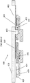
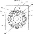
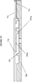
- FIGS 5A , 5B , 5C , 5D , 5E and 5F show a counti ng device 500 having a housing 510, a first counting wheel 520, a second counting wheel 530, a locking mechanism 540, a release mechanism 570 and a second counting wheel rotation mechanism 560.
- Housing 510 has a rectangular shape which is formed from a housing back (not shown) and a housing cover 514. On the surface of the housing cover 514, a housing window 511 is formed. On an inner surface of housing cover 514, a housing peg 512 is provided.
- First counting wheel 520 forms a circumferential inner rail 525 and a circumferential outer rail 528.
- a first counting wheel indexing peg 523 is formed on the circumferential outer rail 528.
- first counting wheel numerals 524 are marked clockwise from 0 to 9. The approximate height of each numeral 524 is about 3.5mm.
- the first counting wheel rail 525 forms first counting wheel rail gaps 526 which are aligned at the anti-clockwise end of numerals 9 and 1.
- the first counting wheel indexing peg 523 is positioned in the gap between numerals 9 and 0.
- Second counting wheel 530 has a transparent disk 536 which bears an inner second counting wheel gear 533 having a second counting wheel gear hub 538.
- the second counting wheel gear 533 has seven second counti ng wheel gear teeth 539 which form seven equally spaced second counting wheel gear indentations 535.
- a second counting wheel gear tooth peg 537 projects downwards.
- second counting wheel numerals 531 are marked clockwise from 1 to 6 between indentations 535.
- the approxi mate height of each numeral 531 is about 3.5mm.
- no numeral is marked on the seventh space between numerals 6 and 1, no numeral is marked.
- second counting wheel gear hub 538 is mounted on housing peg 512 on the inner side of the housing cover 514 such that the second counting wheel 530 overlaps the first counting wheel 520.
- the second counting wheel disk 536 is transparent, the numerals 524 of the first counting wheel 520 arranged beneath the second counting wheel 530 are visible through housing window 511.
- the second counting wheel 530 is locked by locking mechanism 540 such that it cannot rotate.
- the locking mechanism 540 comprises a location mechanism 542 and a rotating locking mechanism 544.
- the location mechanism 542 locks the location of the second counting wheel 530 relative to the housing 510.
- the location mechanism 542 is formed by the second counting wheel gear hub 538 engaging the housi ng peg 512.
- the rotating locking mechanism 544 prevents the second counting wheel 530 from rotating.
- the rotating locking mechanism 544 is formed by second counting wheel gear teeth pegs 537 bearing against first counting wheel inner rail 525 and first counting wheel outer rail 528.
- the second counting wheel 530 is unlocked by the release mechanism 570 such that the second counting wheel 530 can be rotated by the rotation mechanism 560.
- the rotation mechanism 560 comprises second counting wheel gear tooth peg 537 and first counting wheel indexing peg 523.
- the release mechanism 570 comprises second counting wheel gear teeth pegs 537 and first counting wheel inner rail gaps 526.
- the rotation mechanism 560 is activated by second counting wheel gear tooth peg 537 contacting first counting wheel indexing peg 523.
- the second counting wheel 530 is free to rotate because of the activation of release mechanism 570 by second counting wheel gear teeth pegs 537 moving through first counting wheel inner rail gaps 526.
- the second counting wheel 530 is free to rotate by one second counting wheel gear indentation 535 such that a different second counti ng wheel numeral 531 is shown through housing window 511. After rotation of the second counting wheel 530, the positions of the first and second counting wheels 520,530 return to the first configuration.
- the counting device 500 is configured to count downwards from a number of counts which is at most 69 such that the counting device 500 can be used as a remaining dose counting device in a medicament dispenser, for example. If the numerals are marked anti-clockwise on the first counti ng wheel 520 and second counting wheel 530, the counting device 500 could be used to count upwards to a maxi mum of 69. It will be understood by a person of skill in the art that the number from or to which the counting device 500 counts down or up, respectively, may be varied by changing the number of indentations 532 formed by second counting wheel transparent disk 536 and corresponding second counting wheel gear indentations 535 formed by second counting wheel gear 533.
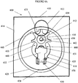
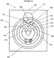
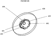
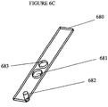
- FIGS. 6A , 6B , 6C and 6D show a counting device 600 having a housing 610, a first counting wheel 620, a second counting wheel 630, a locking mechanism 640, a release mechanism 670 and a second counting wheel rotation mechanism 660.
- Housing 610 has a square shape and comprises a moving bearing plate 680. On the upper surface of housing 610, a housing window 611 is formed. Housing 610 has a housing peg 612 and a housing slot 613 for receiving the moving bearing plate 680.
- Moving bearing plate 680 has a moving bearing plate slot 681 through which housing peg 612 extends, a moving bearing plate peg 682 and a moving bearing plate hole 683.
- First counting wheel 620 has a first counting wheel indexing peg 623 on its surface.
- First counting wheel 620 is marked with indicia (not shown) in the form of numerals which may be marked clockwise from 0 to 9.
- the first counting wheel cam track 621 forms a first counting wheel cam 622.
- Second counting wheel 630 is transparent in at least an annular surface which covers the indicia of the first counting wheel 620 such that the indicia of the first counting wheel 620 are visible.
- Second counting wheel 630 has an upper and a lower surface.
- Second counting wheel 630 has a second counting wheel peg 691 at the centre of its upper surface. The lower surface of second counting wheel 630 rests on the first counting wheel.
- Formed in the lower surface of the second counting wheel 630 are second counting wheel rotation track 693 and seven second counting wheel rotation indentations 692.
- Formed in the upper surface of the second counting wheel 630 are second counting wheel rotation lock track 695 and seven second counting wheel rotation lock indentations 694.
- second counting wheel indicia are marked clockwise from 1 to 6 and a space is provided on which no numeral is marked.
- the space on which no numeral is marked may be coloured. A coloured tint on the space with no numeral is useful where the counting device 600 is used to count remaining items in a dispenser as it highlights the proximity of the count to zero.
- second counting wheel peg 691 slots into moving bearing plate hole 683.
- Housing peg 612 extends through moving bearing plate slot 681 into second counting wheel rotation lock track 695 on the upper surface of second counti ng wheel 630.
- First counting wheel indexing peg 623 is inserted into second counting wheel rotation track 693 on the lower surface of second counting wheel 630.
- Moving bearing plate peg 682 is inserted into first counting wheel cam track 621.
- the numerals (not shown) of the first counting wheel 620 arranged beneath the second counting wheel 630 are visible through housing wi ndow 611.
- the orientation of the second counting wheel 630 is locked by locking mechanism 640.
- the orientation of the second counting wheel 630 may be changed by rotation mechanism 660.
- the second counting wheel 630 is moved from its first configuration to its second configuration by release mechanism 670 which comprises the first counting wheel cam 622 and moving bearing plate peg 682.
- the locking mechanism 640 comprises a location mechanism 642 and a rotating locking mechanism 644.
- the location mechanism 642 restricts movement of the second counting wheel 630 relative to the housi ng 610 to movement along moving bearing plate slot 681.
- the location mechanism 642 is formed by the second counting wheel peg 691 engaging the moving bearing plate hole 683.
- the rotati ng locki ng mechanism 644 prevents the second counti ng wheel 630 from rotating.
- the rotating locking mechanism 644 is formed by a second counting wheel rotation lock indentation 694 engaging housing peg 612. The rotating locking mechanism 644 is released by release mechanism 670.
- the rotation mechanism 660 is formed by a second counting wheel rotation indentation 692 engaging first counting wheel indexing peg 623 such that rotation of first counting wheel 620 causes simultaneous rotation of second counting wheel 630.
- first counting wheel cam 622 releases moving bearing plate peg 682 such that second counting wheel 630 moves back to its first configuration where housing peg 612 engages the next second counting wheel rotation lock indentation 694 such that the second counting wheel 630 is locked in configuration by rotating locking mechanism 644.
- the counti ng device 600 is configured to count downwards from a number of counts which is at most 69 such that the counting device 600 can be used as a remaining dose counting device in a medicament dispenser, for example. If the numerals are marked anti-clockwise on the first counti ng wheel 620 and second counting wheel 630, the counting device 600 could be used to count upwards to a maxi mum of 69. It will be understood by a person of skill in the art that the number from or to which the counting device 600 counts down or up, respectively, may be varied by changing the number of second counting wheel rotation indentations 692 and second counting wheel rotation lock indentations 694.
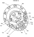
- Figures 7A , 7B , 7C , 7D show a counti ng device 700A having a housi ng (not shown), a first counting wheel 720, a second counting wheel 730A, a locking mechanism 740, a release mechanism 770 and a second counting wheel rotation mechanism 760.
- Housing (not shown) has a housing window 711.
- First counting wheel 720 forms a first counting wheel circumferential rail 725 and a first counting wheel hub 796.
- a fi rst counting wheel indexing peg 723 is formed between the first counting wheel hub 796 and the first counting wheel circumferential rail 725 with sufficient space between the first counting wheel indexing peg 723 and the first counting wheel circumferential rail 725 for a second counting wheel peg 737A to pass.
- On an outer annul ar surface of first counting wheel 720 first counting wheel indicia 724 are marked clockwise in the form of numerals from 0 to 9. The approximate height of each numeral 724 is about 3.5mm.
- the first counting wheel rail 725 forms first counting wheel rail gaps 726 which are aligned at the anti-clockwise end of numerals 9 and 0.
- the first counting wheel indexing peg 723 is positioned in the gap between numerals 9 and 0.
- Second counting wheel 730A is a transparent disk which has a hub 797 and which bears eight second counti ng wheel pegs 737A arranged in a circle on its lower surface.
- second counting wheel indicia 731 are marked clockwise in the form of numerals from 1 to 6, each aligned with a second counting wheel peg 737A.
- the approximate height of each numeral 731 is about 3.5mm.
- no numeral is marked.
- second counting wheel gear hub 797 is mounted on a housing peg (not shown) such that the second counting wheel 730A overlaps the first counting wheel 720.
- the numerals 724 of the first counting wheel 720 arranged beneath the second counting wheel 730A are visible through housi ng window 711.
- the second counting wheel 730A is locked by locking mechanism 740 such that it cannot rotate.
- the locking mechanism 740 comprises a location mechanism 742 and a rotating locking mechanism 744.
- the location mechanism 742 locks the location of the second counting wheel 730 relative to the housing (not shown).
- the location mechanism 742 is formed by the second counti ng wheel hub 797 engaging a housing peg (not shown).
- the rotating locking mechanism 744 prevents the second counting wheel 730 from rotating.
- the rotating locking mechanism 744 is formed by second counting wheel pegs 737A bearing against first counting wheel rai I 725.
- the second counti ng wheel 730A is unlocked by the release mechanism 770 such that the second counting wheel 730A can be rotated by the rotation mechanism 760.
- the rotation mechanism 760 comprises second counting wheel peg 737A and first counting wheel indexing peg 723.
- the release mechanism 770 comprises second counting wheel pegs 737A and first counting wheel rail gaps 726.
- the rotation mechanism 760 is activated by second counting wheel peg 737A contacting first counting wheel indexing peg 723.
- the second counting wheel 730A is free to rotate because of the activation of release mechanism 770 by second counting wheel pegs 737A moving through first counti ng wheel inner rail gaps 726.
- the second counting wheel 730 is free to rotate by one second counting wheel peg 737A such that a different second counti ng wheel numeral 731 is shown through housi ng window 711. After rotation of the second counti ng wheel 730A, the positions of the first and second counti ng wheels 720,730A return to the first configuration.
- the counti ng device 700 is configured to count downwards from a number of counts which is at most 69 such that the counting device 700 can be used as a remaining dose counting device in a medicament dispenser, for example. If the numerals are marked anti-clockwise on the first counti ng wheel 720 and second counting wheel 730A, the counting device 700 could be used to count upwards to a maxi mum of 69. It will be understood by a person of skill in the art that the number from or to which the counting device 700 counts down or up, respectively, may be varied by changi ng the number of second counti ng wheel pegs 737A.
- Figure 7E shows a counting device 700B.
- the counting device 700B is an alternative arrangement to counti ng device 700A.
- the mechanism of counti ng device 700B is the same as that of counti ng device 700A but the second counti ng wheel 730B is not transparent. Instead, the second counti ng wheel 730B only partially covers the first counti ng wheel 720. Thus, in the housi ng window 711, the first counting wheel indicia 724 can be viewed directly.
- the second counting wheel 730B is thin (having a thickness of 400 ⁇ m or less, for example 200 ⁇ m or less) at the edge. This arrangement provides a display that is almost as clear as using transparent effects, but without requiring transparent materials. This alternative arrangement can also be applied in other embodiments.
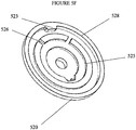
- FIG. 7F shows a counting device 700C.
- the counting device 700C is an alternative arrangement to counti ng device 700A,700B.
- Counting device 700C is identical to counting device 700A except that the second counti ng wheel pegs 737A of counti ng device 700A have been replaced with second counti ng wheel pegs 737B which have two tear drop shaped pegs 737C and a half peg 737D arranged between them which form a non-release rotational locking mechanism 744A in combination with first counting wheel rail 725 such that after seven rotations of the second counti ng wheel 730A,B, it is not possible to rotate the second counting wheel. This is because second counting wheel half peg 737D does not engage the first counting wheel indexing peg 723.
- This alternative embodiment may also be applied to other embodiments. It has the advantage of preventing the counting device 700C displaying an erroneous count.
- the verb "comprise” has its normal dictionary meaning, to denote non-exclusive inclusion. That is, use of the word “comprise” (or any of its derivatives) to include one feature or more, does not exclude the possibility of also including further features.
- the word 'preferable_ (or any of its derivates) indicates one feature or more that is preferred but not essential.
- the invention is not restricted to the details of the foregoi ng embodi ment(s).
Landscapes
- Physics & Mathematics (AREA)
- General Physics & Mathematics (AREA)
- Engineering & Computer Science (AREA)
- Theoretical Computer Science (AREA)
- Infusion, Injection, And Reservoir Apparatuses (AREA)
Priority Applications (2)
| Application Number | Priority Date | Filing Date | Title |
|---|---|---|---|
| PL15820234T PL3230929T3 (pl) | 2014-12-10 | 2015-12-10 | Udoskonalenia w zliczających urządzeniach |
| EP19211329.8A EP3640854B1 (en) | 2014-12-10 | 2015-12-10 | Improvements in counting devices |
Applications Claiming Priority (2)
| Application Number | Priority Date | Filing Date | Title |
|---|---|---|---|
| GBGB1421983.6A GB201421983D0 (en) | 2014-12-10 | 2014-12-10 | Improvements in counting devices |
| PCT/GB2015/000323 WO2016092252A1 (en) | 2014-12-10 | 2015-12-10 | Improvements in counting devices |
Related Child Applications (1)
| Application Number | Title | Priority Date | Filing Date |
|---|---|---|---|
| EP19211329.8A Division EP3640854B1 (en) | 2014-12-10 | 2015-12-10 | Improvements in counting devices |
Publications (2)
| Publication Number | Publication Date |
|---|---|
| EP3230929A1 EP3230929A1 (en) | 2017-10-18 |
| EP3230929B1 true EP3230929B1 (en) | 2019-11-27 |
Family
ID=52425774
Family Applications (2)
| Application Number | Title | Priority Date | Filing Date |
|---|---|---|---|
| EP15820234.1A Active EP3230929B1 (en) | 2014-12-10 | 2015-12-10 | Improvements in counting devices |
| EP19211329.8A Active EP3640854B1 (en) | 2014-12-10 | 2015-12-10 | Improvements in counting devices |
Family Applications After (1)
| Application Number | Title | Priority Date | Filing Date |
|---|---|---|---|
| EP19211329.8A Active EP3640854B1 (en) | 2014-12-10 | 2015-12-10 | Improvements in counting devices |
Country Status (9)
| Country | Link |
|---|---|
| US (2) | US11037047B2 (enExample) |
| EP (2) | EP3230929B1 (enExample) |
| JP (1) | JP6787917B2 (enExample) |
| DK (1) | DK3230929T3 (enExample) |
| ES (1) | ES2772327T3 (enExample) |
| GB (1) | GB201421983D0 (enExample) |
| PL (1) | PL3230929T3 (enExample) |
| PT (1) | PT3230929T (enExample) |
| WO (1) | WO2016092252A1 (enExample) |
Families Citing this family (10)
| Publication number | Priority date | Publication date | Assignee | Title |
|---|---|---|---|---|
| GB201421983D0 (en) * | 2014-12-10 | 2015-01-21 | Coalesce Product Dev Ltd | Improvements in counting devices |
| WO2020163473A1 (en) * | 2019-02-06 | 2020-08-13 | Lupin Inc. | Dose feedback mechanisms and assemblies for user feedback |
| WO2021064700A1 (en) * | 2019-10-04 | 2021-04-08 | Lupin Limited | Event status apparatuses and related devices, systems, and methods |
| CN116210004A (zh) * | 2020-07-23 | 2023-06-02 | 鲁平股份有限公司 | 用于药剂分配器的剂量计数器组件 |
| CN114689078B (zh) * | 2022-05-31 | 2022-08-26 | 山东富源勘察测绘设计有限公司 | 一种城乡道路规划用测绘装置 |
| CN114918718B (zh) * | 2022-06-08 | 2024-01-12 | 青岛雷悦重工股份有限公司 | 一种机械加工用工件加工进度记录装置 |
| DE102022208428A1 (de) * | 2022-08-12 | 2024-02-15 | Hahn-Schickard-Gesellschaft für angewandte Forschung e.V. | Grenzwertdetektionsvorrichtung mit zähleinheit |
| EP4661942A2 (en) * | 2023-02-06 | 2025-12-17 | Transpire Bio Inc. | Dose counter subassemblies for use in dry powder inhalers |
| CN116725705A (zh) * | 2023-08-16 | 2023-09-12 | 科弛医疗科技(北京)有限公司 | 手术器械、手术操作设备以及手术机器人 |
| EP4621642A1 (en) | 2024-03-22 | 2025-09-24 | Sandoz International Gmbh | Counting arrangement for a medical dispenser device |
Family Cites Families (31)
| Publication number | Priority date | Publication date | Assignee | Title |
|---|---|---|---|---|
| FR323270A (fr) * | 1902-07-28 | 1903-03-02 | Evershed Sydney | Appareil perfectionné pour compter une suite de révolutions |
| GB294904A (enExample) * | 1927-07-29 | 1928-09-27 | Rene Leon Jacques Laurent De La Ville Le Roulx | |
| US1962923A (en) * | 1930-09-18 | 1934-06-12 | Landis & Gyr Ag | Prepayment meter |
| NL42702C (enExample) * | 1934-10-13 | |||
| CH350821A (fr) * | 1958-12-02 | 1960-12-15 | Borel Onesime | Totalisateur de compteur |
| US3605517A (en) * | 1969-07-17 | 1971-09-20 | Gd Spa | Immediate locking or stalling geneva wheel device having a high positioning degree or index for the intermittent member by a plurality of locking or stalling parts (centering elements) |
| US3760519A (en) * | 1972-01-03 | 1973-09-25 | M Niven | Golf score counter |
| US3874587A (en) * | 1974-05-06 | 1975-04-01 | Sperry Rand Corp | Mechanical counter system for altimetric displays |
| US4317385A (en) * | 1979-04-11 | 1982-03-02 | Advance Automation Assembly Limited | Geneva mechanism |
| US4531051A (en) * | 1984-01-30 | 1985-07-23 | Westinghouse Electric Corp. | Meter register with incremental indicia wheel movement |
| CA2172537A1 (en) * | 1993-09-22 | 1995-03-30 | Gage Garby | Indicator device responsive to axial force |
| FR2721106B1 (fr) * | 1994-06-10 | 1996-09-13 | Step | Compteur de doses pour inhalateurs. |
| WO1998052634A1 (en) | 1997-05-23 | 1998-11-26 | Pa Knowledge Limited | Inhaler mechanism |
| GB9807558D0 (en) * | 1998-04-09 | 1998-06-10 | Bason Neil P | An indicator device |
| US6082358A (en) * | 1998-05-05 | 2000-07-04 | 1263152 Ontario Inc. | Indicating device for aerosol container |
| DE19901576A1 (de) * | 1999-01-16 | 2000-07-20 | Agfa Gevaert Ag | Zählvorrichtung, vorzugsweise Bildzählvorrichtung für eine Kamera, und Kamera mit Bildzählvorrichtung |
| GB2372542B (en) * | 2001-02-23 | 2003-08-20 | Bespak Plc | Dosage counting devices |
| FR2830527B1 (fr) | 2001-10-04 | 2004-08-27 | Valois Sa | Compteur de doses pour distributeur de produit fluide |
| DE60239639D1 (de) | 2002-07-31 | 2011-05-12 | Chiesi Farma Spa | Pulverinhalator |
| GB0315509D0 (en) * | 2003-07-02 | 2003-08-06 | Meridica Ltd | Dispensing device |
| KR101105909B1 (ko) | 2004-02-16 | 2012-01-17 | 글락소 그룹 리미티드 | 약품 분배기에 사용되는 카운터 |
| GB0519151D0 (en) | 2005-09-20 | 2005-10-26 | Aventis Pharma Ltd | Inhaler |
| GB0600070D0 (en) * | 2006-01-04 | 2006-02-15 | Campling Nicholas J | Dose counter |
| GB0605150D0 (en) * | 2006-03-14 | 2006-04-26 | Glaxo Group Ltd | Counter For Use With A Medicament Dispenser |
| JP5102285B2 (ja) * | 2006-04-21 | 2012-12-19 | スリーエム イノベイティブ プロパティズ カンパニー | 投与量カウンター |
| ES2649756T3 (es) * | 2008-02-18 | 2018-01-15 | Glaxo Group Limited | Contador de accionamientos |
| ES2662769T3 (es) * | 2009-05-18 | 2018-04-09 | Adamis Pharmaceuticals Corporation | Contadores de dosis de inhalador de polvo seco |
| US9345848B2 (en) * | 2009-10-20 | 2016-05-24 | Sima Patent Ve Lisanslama Hizmetleri Ltd. Sti. | Dry powder inhaler |
| GB2491611B (en) * | 2011-06-08 | 2014-01-01 | Consort Medical Plc | Dose indicator device |
| GB201421983D0 (en) * | 2014-12-10 | 2015-01-21 | Coalesce Product Dev Ltd | Improvements in counting devices |
| GB201812671D0 (en) * | 2018-08-03 | 2018-09-19 | Coalesce Product Dev Ltd | An inhaler device |
-
2014
- 2014-12-10 GB GBGB1421983.6A patent/GB201421983D0/en not_active Ceased
-
2015
- 2015-12-10 PL PL15820234T patent/PL3230929T3/pl unknown
- 2015-12-10 EP EP15820234.1A patent/EP3230929B1/en active Active
- 2015-12-10 WO PCT/GB2015/000323 patent/WO2016092252A1/en not_active Ceased
- 2015-12-10 JP JP2017549852A patent/JP6787917B2/ja active Active
- 2015-12-10 EP EP19211329.8A patent/EP3640854B1/en active Active
- 2015-12-10 DK DK15820234.1T patent/DK3230929T3/da active
- 2015-12-10 PT PT158202341T patent/PT3230929T/pt unknown
- 2015-12-10 ES ES15820234T patent/ES2772327T3/es active Active
- 2015-12-10 US US15/534,356 patent/US11037047B2/en active Active
-
2021
- 2021-05-18 US US17/323,554 patent/US20210271955A1/en not_active Abandoned
Non-Patent Citations (1)
| Title |
|---|
| None * |
Also Published As
| Publication number | Publication date |
|---|---|
| US20170364789A1 (en) | 2017-12-21 |
| ES2772327T8 (es) | 2020-08-05 |
| PT3230929T (pt) | 2020-02-20 |
| JP6787917B2 (ja) | 2020-11-18 |
| US20210271955A1 (en) | 2021-09-02 |
| JP2018500711A (ja) | 2018-01-11 |
| EP3640854A1 (en) | 2020-04-22 |
| EP3640854C0 (en) | 2023-11-29 |
| WO2016092252A1 (en) | 2016-06-16 |
| US11037047B2 (en) | 2021-06-15 |
| ES2772327T3 (es) | 2020-07-07 |
| PL3230929T3 (pl) | 2020-06-01 |
| EP3230929A1 (en) | 2017-10-18 |
| DK3230929T3 (da) | 2020-02-24 |
| HK1245461A1 (en) | 2018-08-24 |
| EP3640854B1 (en) | 2023-11-29 |
| GB201421983D0 (en) | 2015-01-21 |
Similar Documents
| Publication | Publication Date | Title |
|---|---|---|
| EP3230929B1 (en) | Improvements in counting devices | |
| JP2018500711A5 (enExample) | ||
| US7827989B2 (en) | Mechanical doses counter for a powder inhaler | |
| ES2921362T3 (es) | Contador para su uso con un dispensador de medicamentos | |
| US9713685B2 (en) | Dose counter | |
| CN109641116B (zh) | 计数机构 | |
| US20140053838A1 (en) | Dose counter assembly for inhaler | |
| US20250073401A1 (en) | Counter structure of dry powder aerosol delivery system | |
| WO2007077450A2 (en) | Dose counter with an odometer type display | |
| HK1245461B (en) | Improvements in counting devices | |
| HK40018793A (en) | Improvements in counting devices | |
| HK40018793B (en) | Improvements in counting devices | |
| EP4621642A1 (en) | Counting arrangement for a medical dispenser device | |
| US764778A (en) | Counter. | |
| OA16776A (en) | A dose counter. |
Legal Events
| Date | Code | Title | Description |
|---|---|---|---|
| STAA | Information on the status of an ep patent application or granted ep patent |
Free format text: STATUS: THE INTERNATIONAL PUBLICATION HAS BEEN MADE |
|
| PUAI | Public reference made under article 153(3) epc to a published international application that has entered the european phase |
Free format text: ORIGINAL CODE: 0009012 |
|
| STAA | Information on the status of an ep patent application or granted ep patent |
Free format text: STATUS: REQUEST FOR EXAMINATION WAS MADE |
|
| 17P | Request for examination filed |
Effective date: 20170707 |
|
| AK | Designated contracting states |
Kind code of ref document: A1 Designated state(s): AL AT BE BG CH CY CZ DE DK EE ES FI FR GB GR HR HU IE IS IT LI LT LU LV MC MK MT NL NO PL PT RO RS SE SI SK SM TR |
|
| AX | Request for extension of the european patent |
Extension state: BA ME |
|
| DAV | Request for validation of the european patent (deleted) | ||
| DAX | Request for extension of the european patent (deleted) | ||
| REG | Reference to a national code |
Ref country code: HK Ref legal event code: DE Ref document number: 1245461 Country of ref document: HK |
|
| STAA | Information on the status of an ep patent application or granted ep patent |
Free format text: STATUS: EXAMINATION IS IN PROGRESS |
|
| 17Q | First examination report despatched |
Effective date: 20180829 |
|
| GRAP | Despatch of communication of intention to grant a patent |
Free format text: ORIGINAL CODE: EPIDOSNIGR1 |
|
| STAA | Information on the status of an ep patent application or granted ep patent |
Free format text: STATUS: GRANT OF PATENT IS INTENDED |
|
| INTG | Intention to grant announced |
Effective date: 20190918 |
|
| GRAS | Grant fee paid |
Free format text: ORIGINAL CODE: EPIDOSNIGR3 |
|
| GRAA | (expected) grant |
Free format text: ORIGINAL CODE: 0009210 |
|
| STAA | Information on the status of an ep patent application or granted ep patent |
Free format text: STATUS: THE PATENT HAS BEEN GRANTED |
|
| RAP1 | Party data changed (applicant data changed or rights of an application transferred) |
Owner name: COALESCE PRODUCT DEVELOPMENT LTD |
|
| AK | Designated contracting states |
Kind code of ref document: B1 Designated state(s): AL AT BE BG CH CY CZ DE DK EE ES FI FR GB GR HR HU IE IS IT LI LT LU LV MC MK MT NL NO PL PT RO RS SE SI SK SM TR |
|
| REG | Reference to a national code |
Ref country code: GB Ref legal event code: FG4D |
|
| REG | Reference to a national code |
Ref country code: CH Ref legal event code: EP |
|
| REG | Reference to a national code |
Ref country code: AT Ref legal event code: REF Ref document number: 1207533 Country of ref document: AT Kind code of ref document: T Effective date: 20191215 |
|
| REG | Reference to a national code |
Ref country code: DE Ref legal event code: R096 Ref document number: 602015042639 Country of ref document: DE |
|
| REG | Reference to a national code |
Ref country code: IE Ref legal event code: FG4D |
|
| REG | Reference to a national code |
Ref country code: CH Ref legal event code: PCAR Free format text: NEW ADDRESS: ROUTE DU COUTSET 18, 1485 NUVILLY (CH) |
|
| REG | Reference to a national code |
Ref country code: FI Ref legal event code: FGE |
|
| REG | Reference to a national code |
Ref country code: PT Ref legal event code: SC4A Ref document number: 3230929 Country of ref document: PT Date of ref document: 20200220 Kind code of ref document: T Free format text: AVAILABILITY OF NATIONAL TRANSLATION Effective date: 20200210 |
|
| REG | Reference to a national code |
Ref country code: DK Ref legal event code: T3 Effective date: 20200217 |
|
| REG | Reference to a national code |
Ref country code: SE Ref legal event code: TRGR |
|
| REG | Reference to a national code |
Ref country code: NL Ref legal event code: FP |
|
| REG | Reference to a national code |
Ref country code: CH Ref legal event code: NV Representative=s name: TR-IP CONSULTING LLC, CH |
|
| REG | Reference to a national code |
Ref country code: LT Ref legal event code: MG4D |
|
| PG25 | Lapsed in a contracting state [announced via postgrant information from national office to epo] |
Ref country code: LT Free format text: LAPSE BECAUSE OF FAILURE TO SUBMIT A TRANSLATION OF THE DESCRIPTION OR TO PAY THE FEE WITHIN THE PRESCRIBED TIME-LIMIT Effective date: 20191127 Ref country code: NO Free format text: LAPSE BECAUSE OF FAILURE TO SUBMIT A TRANSLATION OF THE DESCRIPTION OR TO PAY THE FEE WITHIN THE PRESCRIBED TIME-LIMIT Effective date: 20200227 Ref country code: BG Free format text: LAPSE BECAUSE OF FAILURE TO SUBMIT A TRANSLATION OF THE DESCRIPTION OR TO PAY THE FEE WITHIN THE PRESCRIBED TIME-LIMIT Effective date: 20200227 Ref country code: LV Free format text: LAPSE BECAUSE OF FAILURE TO SUBMIT A TRANSLATION OF THE DESCRIPTION OR TO PAY THE FEE WITHIN THE PRESCRIBED TIME-LIMIT Effective date: 20191127 |
|
| REG | Reference to a national code |
Ref country code: GR Ref legal event code: EP Ref document number: 20200400371 Country of ref document: GR Effective date: 20200511 |
|
| PG25 | Lapsed in a contracting state [announced via postgrant information from national office to epo] |
Ref country code: HR Free format text: LAPSE BECAUSE OF FAILURE TO SUBMIT A TRANSLATION OF THE DESCRIPTION OR TO PAY THE FEE WITHIN THE PRESCRIBED TIME-LIMIT Effective date: 20191127 Ref country code: IS Free format text: LAPSE BECAUSE OF FAILURE TO SUBMIT A TRANSLATION OF THE DESCRIPTION OR TO PAY THE FEE WITHIN THE PRESCRIBED TIME-LIMIT Effective date: 20200327 Ref country code: RS Free format text: LAPSE BECAUSE OF FAILURE TO SUBMIT A TRANSLATION OF THE DESCRIPTION OR TO PAY THE FEE WITHIN THE PRESCRIBED TIME-LIMIT Effective date: 20191127 |
|
| PG25 | Lapsed in a contracting state [announced via postgrant information from national office to epo] |
Ref country code: AL Free format text: LAPSE BECAUSE OF FAILURE TO SUBMIT A TRANSLATION OF THE DESCRIPTION OR TO PAY THE FEE WITHIN THE PRESCRIBED TIME-LIMIT Effective date: 20191127 |
|
| REG | Reference to a national code |
Ref country code: ES Ref legal event code: FG2A Ref document number: 2772327 Country of ref document: ES Kind code of ref document: T3 Effective date: 20200707 |
|
| PG25 | Lapsed in a contracting state [announced via postgrant information from national office to epo] |
Ref country code: RO Free format text: LAPSE BECAUSE OF FAILURE TO SUBMIT A TRANSLATION OF THE DESCRIPTION OR TO PAY THE FEE WITHIN THE PRESCRIBED TIME-LIMIT Effective date: 20191127 Ref country code: EE Free format text: LAPSE BECAUSE OF FAILURE TO SUBMIT A TRANSLATION OF THE DESCRIPTION OR TO PAY THE FEE WITHIN THE PRESCRIBED TIME-LIMIT Effective date: 20191127 |
|
| REG | Reference to a national code |
Ref country code: DE Ref legal event code: R097 Ref document number: 602015042639 Country of ref document: DE |
|
| PG25 | Lapsed in a contracting state [announced via postgrant information from national office to epo] |
Ref country code: SK Free format text: LAPSE BECAUSE OF FAILURE TO SUBMIT A TRANSLATION OF THE DESCRIPTION OR TO PAY THE FEE WITHIN THE PRESCRIBED TIME-LIMIT Effective date: 20191127 Ref country code: SM Free format text: LAPSE BECAUSE OF FAILURE TO SUBMIT A TRANSLATION OF THE DESCRIPTION OR TO PAY THE FEE WITHIN THE PRESCRIBED TIME-LIMIT Effective date: 20191127 Ref country code: MC Free format text: LAPSE BECAUSE OF FAILURE TO SUBMIT A TRANSLATION OF THE DESCRIPTION OR TO PAY THE FEE WITHIN THE PRESCRIBED TIME-LIMIT Effective date: 20191127 |
|
| PLBE | No opposition filed within time limit |
Free format text: ORIGINAL CODE: 0009261 |
|
| STAA | Information on the status of an ep patent application or granted ep patent |
Free format text: STATUS: NO OPPOSITION FILED WITHIN TIME LIMIT |
|
| 26N | No opposition filed |
Effective date: 20200828 |
|
| PG25 | Lapsed in a contracting state [announced via postgrant information from national office to epo] |
Ref country code: SI Free format text: LAPSE BECAUSE OF FAILURE TO SUBMIT A TRANSLATION OF THE DESCRIPTION OR TO PAY THE FEE WITHIN THE PRESCRIBED TIME-LIMIT Effective date: 20191127 |
|
| PG25 | Lapsed in a contracting state [announced via postgrant information from national office to epo] |
Ref country code: CY Free format text: LAPSE BECAUSE OF FAILURE TO SUBMIT A TRANSLATION OF THE DESCRIPTION OR TO PAY THE FEE WITHIN THE PRESCRIBED TIME-LIMIT Effective date: 20191127 |
|
| PG25 | Lapsed in a contracting state [announced via postgrant information from national office to epo] |
Ref country code: HU Free format text: LAPSE BECAUSE OF FAILURE TO SUBMIT A TRANSLATION OF THE DESCRIPTION OR TO PAY THE FEE WITHIN THE PRESCRIBED TIME-LIMIT; INVALID AB INITIO Effective date: 20151210 Ref country code: MT Free format text: LAPSE BECAUSE OF FAILURE TO SUBMIT A TRANSLATION OF THE DESCRIPTION OR TO PAY THE FEE WITHIN THE PRESCRIBED TIME-LIMIT Effective date: 20191127 |
|
| PG25 | Lapsed in a contracting state [announced via postgrant information from national office to epo] |
Ref country code: MK Free format text: LAPSE BECAUSE OF FAILURE TO SUBMIT A TRANSLATION OF THE DESCRIPTION OR TO PAY THE FEE WITHIN THE PRESCRIBED TIME-LIMIT Effective date: 20191127 |
|
| REG | Reference to a national code |
Ref country code: AT Ref legal event code: UEP Ref document number: 1207533 Country of ref document: AT Kind code of ref document: T Effective date: 20191127 |
|
| REG | Reference to a national code |
Ref country code: LU Ref legal event code: PD Owner name: SANDOZ AG; CH Free format text: FORMER OWNER: COALESCE PRODUCT DEVELOPMENT LTD Effective date: 20221031 |
|
| REG | Reference to a national code |
Ref country code: DE Ref legal event code: R081 Ref document number: 602015042639 Country of ref document: DE Owner name: SANDOZ AG, CH Free format text: FORMER OWNER: COALESCE PRODUCT DEVELOPMENT LTD, CAMBRIDGE, GB Ref country code: DE Ref legal event code: R082 Ref document number: 602015042639 Country of ref document: DE Representative=s name: MAIWALD GMBH, DE |
|
| REG | Reference to a national code |
Ref country code: GB Ref legal event code: 732E Free format text: REGISTERED BETWEEN 20221208 AND 20221215 |
|
| REG | Reference to a national code |
Ref country code: AT Ref legal event code: PC Ref document number: 1207533 Country of ref document: AT Kind code of ref document: T Owner name: SANDOZ AG, CH Effective date: 20221213 |
|
| REG | Reference to a national code |
Ref country code: CH Ref legal event code: PK Free format text: BERICHTIGUNGEN |
|
| REG | Reference to a national code |
Ref country code: NL Ref legal event code: PD Owner name: SANDOZ AG; CH Free format text: DETAILS ASSIGNMENT: CHANGE OF OWNER(S), ASSIGNMENT; FORMER OWNER NAME: COALESCE PRODUCT DEVELOPMENT LTD Effective date: 20230424 |
|
| REG | Reference to a national code |
Ref country code: BE Ref legal event code: PD Owner name: SANDOZ AG; CH Free format text: DETAILS ASSIGNMENT: CHANGE OF OWNER(S), ASSIGNMENT; FORMER OWNER NAME: COALESCE PRODUCT DEVELOPMENT LTD Effective date: 20230419 |
|
| REG | Reference to a national code |
Ref country code: ES Ref legal event code: PC2A Owner name: SANDOZ AG Effective date: 20230605 |
|
| REG | Reference to a national code |
Ref country code: FI Ref legal event code: PCE Owner name: SANDOZ AG |
|
| PGFP | Annual fee paid to national office [announced via postgrant information from national office to epo] |
Ref country code: DE Payment date: 20241120 Year of fee payment: 10 |
|
| PGFP | Annual fee paid to national office [announced via postgrant information from national office to epo] |
Ref country code: DK Payment date: 20241212 Year of fee payment: 10 |
|
| PGFP | Annual fee paid to national office [announced via postgrant information from national office to epo] |
Ref country code: GB Payment date: 20241121 Year of fee payment: 10 |
|
| PGFP | Annual fee paid to national office [announced via postgrant information from national office to epo] |
Ref country code: AT Payment date: 20241126 Year of fee payment: 10 |
|
| PGFP | Annual fee paid to national office [announced via postgrant information from national office to epo] |
Ref country code: IE Payment date: 20241126 Year of fee payment: 10 |
|
| PGFP | Annual fee paid to national office [announced via postgrant information from national office to epo] |
Ref country code: IT Payment date: 20241128 Year of fee payment: 10 |
|
| PGFP | Annual fee paid to national office [announced via postgrant information from national office to epo] |
Ref country code: SE Payment date: 20241126 Year of fee payment: 10 |
|
| PGFP | Annual fee paid to national office [announced via postgrant information from national office to epo] |
Ref country code: ES Payment date: 20250121 Year of fee payment: 10 |
|
| PGFP | Annual fee paid to national office [announced via postgrant information from national office to epo] |
Ref country code: CH Payment date: 20250101 Year of fee payment: 10 |
|
| PGFP | Annual fee paid to national office [announced via postgrant information from national office to epo] |
Ref country code: FI Payment date: 20250924 Year of fee payment: 11 Ref country code: PT Payment date: 20250909 Year of fee payment: 11 |
|
| PGFP | Annual fee paid to national office [announced via postgrant information from national office to epo] |
Ref country code: GR Payment date: 20250922 Year of fee payment: 11 |
|
| PGFP | Annual fee paid to national office [announced via postgrant information from national office to epo] |
Ref country code: PL Payment date: 20250911 Year of fee payment: 11 Ref country code: TR Payment date: 20250919 Year of fee payment: 11 |
|
| PGFP | Annual fee paid to national office [announced via postgrant information from national office to epo] |
Ref country code: BE Payment date: 20250924 Year of fee payment: 11 |
|
| PGFP | Annual fee paid to national office [announced via postgrant information from national office to epo] |
Ref country code: FR Payment date: 20250925 Year of fee payment: 11 |
|
| PGFP | Annual fee paid to national office [announced via postgrant information from national office to epo] |
Ref country code: CZ Payment date: 20250910 Year of fee payment: 11 |
|
| PGFP | Annual fee paid to national office [announced via postgrant information from national office to epo] |
Ref country code: LU Payment date: 20251024 Year of fee payment: 11 Ref country code: NL Payment date: 20251010 Year of fee payment: 11 |