EP3230013B1 - Koffer zum aufnehmen von werkzeugen oder kleinteilen - Google Patents
Koffer zum aufnehmen von werkzeugen oder kleinteilen Download PDFInfo
- Publication number
- EP3230013B1 EP3230013B1 EP15804854.6A EP15804854A EP3230013B1 EP 3230013 B1 EP3230013 B1 EP 3230013B1 EP 15804854 A EP15804854 A EP 15804854A EP 3230013 B1 EP3230013 B1 EP 3230013B1
- Authority
- EP
- European Patent Office
- Prior art keywords
- base body
- cover
- case
- web
- labyrinth seal
- Prior art date
- Legal status (The legal status is an assumption and is not a legal conclusion. Google has not performed a legal analysis and makes no representation as to the accuracy of the status listed.)
- Active
Links
Images



Classifications
-
- B—PERFORMING OPERATIONS; TRANSPORTING
- B65—CONVEYING; PACKING; STORING; HANDLING THIN OR FILAMENTARY MATERIAL
- B65D—CONTAINERS FOR STORAGE OR TRANSPORT OF ARTICLES OR MATERIALS, e.g. BAGS, BARRELS, BOTTLES, BOXES, CANS, CARTONS, CRATES, DRUMS, JARS, TANKS, HOPPERS, FORWARDING CONTAINERS; ACCESSORIES, CLOSURES, OR FITTINGS THEREFOR; PACKAGING ELEMENTS; PACKAGES
- B65D53/00—Sealing or packing elements; Sealings formed by liquid or plastics material
-
- B—PERFORMING OPERATIONS; TRANSPORTING
- B25—HAND TOOLS; PORTABLE POWER-DRIVEN TOOLS; MANIPULATORS
- B25H—WORKSHOP EQUIPMENT, e.g. FOR MARKING-OUT WORK; STORAGE MEANS FOR WORKSHOPS
- B25H3/00—Storage means or arrangements for workshops facilitating access to, or handling of, work tools or instruments
- B25H3/02—Boxes
-
- B—PERFORMING OPERATIONS; TRANSPORTING
- B65—CONVEYING; PACKING; STORING; HANDLING THIN OR FILAMENTARY MATERIAL
- B65D—CONTAINERS FOR STORAGE OR TRANSPORT OF ARTICLES OR MATERIALS, e.g. BAGS, BARRELS, BOTTLES, BOXES, CANS, CARTONS, CRATES, DRUMS, JARS, TANKS, HOPPERS, FORWARDING CONTAINERS; ACCESSORIES, CLOSURES, OR FITTINGS THEREFOR; PACKAGING ELEMENTS; PACKAGES
- B65D43/00—Lids or covers for rigid or semi-rigid containers
- B65D43/14—Non-removable lids or covers
- B65D43/16—Non-removable lids or covers hinged for upward or downward movement
- B65D43/163—Non-removable lids or covers hinged for upward or downward movement the container and the lid being made separately
-
- A—HUMAN NECESSITIES
- A45—HAND OR TRAVELLING ARTICLES
- A45C—PURSES; LUGGAGE; HAND CARRIED BAGS
- A45C13/00—Details; Accessories
- A45C13/008—Details; Accessories for making water- or air-tight
-
- A—HUMAN NECESSITIES
- A45—HAND OR TRAVELLING ARTICLES
- A45C—PURSES; LUGGAGE; HAND CARRIED BAGS
- A45C5/00—Rigid or semi-rigid luggage
- A45C5/03—Suitcases
- A45C2005/037—Suitcases with a hard shell, i.e. rigid shell as volume creating element
Definitions
- the invention relates to a case for receiving tools or small parts with a base body and a pivotally hinged lid on the base body, wherein the base body has two side walls, the upper edge of which is exposed when the lid is closed, so that the lid in the closed state between the upper Edges of the side walls of the base body is arranged.
- a case for receiving tools or small parts with a base body and a cover pivotally hinged to the base body.
- the base body has two side walls. The upper edge of the side walls is covered by the lid when the lid is closed, so that when several cases are stacked, the base body of the case rests on the lid of another case. When the lid is closed, a labyrinth seal is formed between the upper edge of the side walls and the lower edge of the lid.
- each side wall of the base body forms a labyrinth seal with the respective side wall of the lid in the closed state of the case.
- a labyrinth seal at least on the side walls of the cover, a reliable seal that is easy to manufacture can be realized.
- Both the lid and the base body of the case are expediently designed as plastic injection molded parts.
- the implementation of a labyrinth seal is then easily possible.
- the provision of a labyrinth seal has the advantage that a sealing effect can be achieved even without additional elastic seals.
- the sealing effect is therefore independent of the exact placement of a seal and independent of its elasticity. This is particularly advantageous for suitcases for tools or small parts for rough construction site operations, since elastic seals are subject to an aging process and can also be damaged comparatively quickly and easily by sunlight, heat or mechanical influences.
- a rear wall of the cover with a rear wall of the base body and a front wall of the cover with a front wall of the base body each form a labyrinth seal, so that the labyrinth seal runs completely around an opening in the case closed by the cover.
- the case can be sealed particularly reliably against the ingress of dirt, moisture and water.
- the labyrinth seal is formed by means of a recess with a U-shaped cross section and a web projecting into the U-shaped recess.
- the U-shaped recess expediently opens in the closing direction of the cover.
- the U-shaped recess on the side walls of the case or the cover is thus U-shaped in a cross section parallel to a front wall of the case and the U-shaped recess on a front wall or rear wall of the base body or cover is parallel to one in cross section Side wall of the case is U-shaped.
- the U-shaped recess is provided on the cover and the web on the sealing section of the side walls of the base body.
- any dirt contained in the U-shaped recess of the cover can fall out of the U-shaped recess when the cover is closed.
- the U-shaped recess is provided on its base with an elastic seal.
- an inner surface of the side wall of the base body facing the opening of the base body that can be closed with the lid forms a continuation of the labyrinth seal with an outer surface of the side wall of the lid.
- the inner surface of the side wall of the base body and the outer surface of the side wall of the cover form boundaries of a groove which is open towards the front and back of the base body.
- the side wall of the base body is provided on the outside with drain holes in the region of the transition to the groove base of the groove formed with the outer surface of the side wall of the cover.
- drain holes water that has possibly penetrated into the groove can flow off quickly.
- the groove is expediently open towards the rear wall and the front wall of the case. The provision of the additional drain holes reliably prevents water from remaining in the groove.
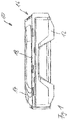
- Fig. 1 shows a side view from obliquely above a case 10 according to the invention, which has a base body 12 and a pivotally hinged to the base body 12 cover 14.
- a pivot hinge 16 which connects the base body 12 and the cover 14, is in Fig. 1 arranged on the right.
- the lid 14 is in the Fig. 1 completely closed state shown arranged within the side walls 18 of the base body 12. In other words, this means that the respective upper edge of the side walls 18 of the base body is exposed when the cover 14 is completely closed.
- Such an internal arrangement of the cover 14 is advantageous, for example, if the case 10 is to be stackable. When stacking a plurality of suitcases 10, a lower edge of the side walls 18 of the case 10 engages in the upper edge of the side wall of another suitcase.
- the lid 14 is not burdened by this. Above all, a stack of several suitcases 10 can then be made very stable, since the stability of the stack is only determined by the base body 12 of the several suitcases, but not by the cover 14. Since the lid is also protected by the respective upper edges of the side walls 18, the lid 14 holds reliably in the closed state even when the case 10 falls down and hits the floor in the region of the upper edge of a side wall 18.
- the representation of the Fig. 2 shows the case 10 of the Fig. 1 with the lid fully open 14. It is already in the representation of the Fig. 2 to recognize that the cover 14 has a circumferential U-shaped recess 19 on its outer edge. This U-shaped recess 19 can be seen in the fully open state of the cover 14, in the closed state of the cover 14 it receives a web 20 surrounding the opening of the base body 12. In the completely closed state of the cover 14, the U-shaped recess 19 and the web 20 engaging in the U-shaped recess 19 then form a labyrinth seal. This all-round labyrinth seal reliably prevents the ingress of dirt, moisture and water into the interior of the case 10.
- the representation of the Fig. 3 shows an enlarged section of the Fig. 2 , namely in the region of the pivotable articulation of the cover 14 to the base body 12.
- the U-shaped recess 19 on the cover 14 can be seen, which is between a circumferential outer web 22 and a likewise circumferential inner web 24 is formed.
- the circumferential web 20 on the base body 12 can also be seen.
- the representation of the Fig. 4 shows the case 10 of the Fig. 2 from a different angle from above. Again, the circumferential web 20 can be seen on the base body 12.
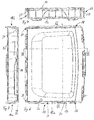
- the representation of the Fig. 6 shows the closed case 10 of the Fig. 1 in a top view. It can be clearly seen that the groove between the upper edge of the side walls 18 and the web 22, which forms the lateral boundary of the lid 14, is open to the front of the case and to the rear of the case, see points 28, 30 at these points 28, 30 water can flow out of this groove.
- the drain openings 26, which also drain this groove, are shown in FIG Fig. 6 merely hinted at.
- FIG. 7 shows a view of the section plane VII-VII in Fig. 6 . It can be seen how the circumferential web 20, which surrounds the opening of the base body 12, engages in the U-shaped recess on the lid 14 and thereby between the lid 14 and the base body 12 in the region of a rear wall 21 and a front wall 23 of the case 10 realized a labyrinth seal when closed.
- FIG. 8 shows a view of the section plane VIII-VIII in Fig. 6 . Also Fig. 8 it can be seen how the web 20 encircling the opening of the base body 12 engages in the U-shaped recess on the cover 14 and thereby realizes a labyrinth seal in the region of the side walls 18a, 18b of the case 10.
- the representation of the Fig. 9 shows detail IX Fig. 8 enlarged.
- the U-shaped groove is formed, into which the web 20, which runs around the opening of the base body 12, extends.
- a seal 30 is injected into the cover 14, on which the upper edge of the web 20 rests.
- the seal 30 runs like the webs 24, 26 around the entire circumference of the cover 14. The seal 30 is accommodated within the U-shaped recess in a manner protected against solar radiation and mechanical damage.
- Fig. 9 it can also be seen that an in Fig. 9 the outer surface of the web 20 on the right, with the upper edge of the side wall 18a of the base body 12, forms a further U-shaped recess into which the web 26 of the cover 14 extends. As already stated, the labyrinth seal between the web 20 and the cover 14 is thereby continued.
- the case 10 is, see Fig. 8 , constructed in the same way on the opposite side wall 18b.
- Fig. 9 it can also be seen that in the illustrated fully closed state of the cover, a lower edge of the web 26 of the cover 14 lies against the base of the U-shaped groove between the web 20 and the upper edge of the side wall 18a.
- a completely closed position of the cover is thereby precisely defined and there is in particular no need to fear that the seal 30 is compressed too much and thus loses its elasticity over time.
Landscapes
- Engineering & Computer Science (AREA)
- Mechanical Engineering (AREA)
- Closures For Containers (AREA)
- Purses, Travelling Bags, Baskets, Or Suitcases (AREA)
- Packaging Of Annular Or Rod-Shaped Articles, Wearing Apparel, Cassettes, Or The Like (AREA)
- Casings For Electric Apparatus (AREA)
Description
- Die Erfindung betrifft einen Koffer zum Aufnehmen von Werkzeugen oder Kleinteilen mit einem Grundkörper und einem an dem Grundkörper schwenkbar angelenkten Deckel, wobei der Grundkörper zwei Seitenwände aufweist, deren oberer Rand im geschlossenen Zustand des Deckels freiliegt, so dass der Deckel im geschlossenen Zustand zwischen den oberen Rändern der Seitenwände des Grundkörpers angeordnet ist.
- Aus der US-Patentschrift
US 4,972,527 ist ein Koffer zum Aufnehmen von Werkzeugen oder Kleinteilen mit einem Grundkörper und einem an dem Grundkörper schwenkbar angelenkten Deckel bekannt. Der Grundkörper weist zwei Seitenwände auf. Der obere Rand der Seitenwände ist im geschlossenen Zustand des Deckels durch den Deckel abgedeckt, so dass beim Stapeln mehrerer Koffer der Grundkörper des Koffers auf dem Deckel eines weiteren Koffers aufliegt. Im geschlossenen Zustand des Deckels wird zwischen dem jeweils oberen Rand der Seitenwände und dem unteren Rand des Deckels eine Labyrinthdichtung gebildet. - Aus der US-Offenlegungsschrift
US 2012/0312708 A1 ist ein Koffer zum Aufnehmen von Werkzeugen oder Kleinteilen mit einem Grundkörper und einem an dem Grundkörper schwenkbar angelenkten Deckel bekannt, wobei der Grundkörper zwei Seitenwände aufweist, deren oberer Rand im geschlossenen Zustand des Deckels freiliegt, so dass der Deckel im geschlossenen Zustand zwischen den oberen Rändern der Seitenwände des Grundkörpers angeordnet ist und beim Stapeln mehrerer Koffer ein unterer Rand der Seitenwände des Koffers in den unteren Rand der Seitenwand eines weiteren Koffers eingreift. Diese Offenlegungsschrift offenbart einen Koffer nach dem Oberbegriff des Anspruchs 1. - Aus der internationalen Offenlegungsschrift
WO 2011/032568 A1 ist ein Koffer zum Aufnehmen von Werkzeugen oder Kleinteilen mit einem Grundkörper und einem an dem Grundkörper schwenkbar angelenkten Deckel bekannt. Im geschlossenen Zustand des Deckels ist zwischen dem unteren Rand der Seitenwand des Deckels und dem oberen Rand der Seitenwand des Grundkörpers eine Labyrinthdichtung ausgebildet. - Aus der deutschen Offenlegungsschrift
DE 195 12 301 A1 ist ein Koffer bekannt, bei dem zwischen dem unteren Rand der Seitenwand des Deckels und dem oberen Rand der Seitenwand des Grundkörpers eine Labyrinthdichtung ausgebildet ist. - Aus der britischen Offenlegungsschrift
GB 2 437 513 A - Mit der Erfindung soll ein Koffer hinsichtlich seiner Abdichtung gegen Schmutz, Feuchtigkeit und Wasser verbessert werden.
- Erfindungsgemäß ist hierzu ein Koffer mit den Merkmalen von Anspruch 1 vorgesehen. Vorteilhafte Weiterbildungen der Erfindung sind in den Unteransprüchen angegeben.
- Bei einem Koffer zum Aufnehmen von Werkzeugen oder Kleinteilen mit einem Grundkörper und einem an dem Grundkörper schwenkbar angelenkten Deckel, wobei der Grundkörper zwei Seitenwände aufweist, deren oberer Rand im geschlossenen Zustand des Deckels freiliegt, so dass der Deckel im geschlossenen Zustand zwischen den oberen Rändern der Seitenwände des Grundkörpers angeordnet ist, ist vorgesehen, dass jede Seitenwand des Grundkörpers mit der jeweiligen Seitenwand des Deckels im geschlossenen Zustand des Koffers eine Labyrinthdichtung bildet.
- Durch Vorsehen einer Labyrinthdichtung wenigstens an den Seitenwänden des Deckels kann eine zuverlässige und dabei einfach herstellbare Abdichtung realisiert werden. Zweckmäßigerweise werden sowohl der Deckel als auch der Grundkörper des Koffers als Kunststoffspritzgussteile ausgeführt. Die Realisierung einer Labyrinthdichtung ist dann problemlos möglich. Das Vorsehen einer Labyrinthdichtung hat den Vorteil, dass eine Dichtwirkung sogar ohne zusätzliche elastische Dichtungen erzielt werden kann. Die Abdichtwirkung ist damit unabhängig von der exakten Platzierung einer Dichtung sowie unabhängig von deren Elastizität. Gerade bei Koffern für Werkzeuge oder Kleinteile für den rauen Baustellenbetrieb ist dies von großem Vorteil, da elastische Dichtungen einem Alterungsprozess unterliegen sowie auch vergleichsweise schnell und leicht durch Sonneneinstrahlung, Hitze oder mechanische Einwirkung beschädigt werden können.
- In Weiterbildung der Erfindung bilden eine Rückwand des Deckels mit einer Rückwand des Grundkörpers und eine Vorderwand des Deckels mit einer Vorderwand des Grundkörpers jeweils eine Labyrinthdichtung, so dass die Labyrinthdichtung um eine mittels des Deckels verschlossene Öffnung des Koffers vollständig umläuft.
- Mittels einer umlaufenden Labyrinthdichtung lässt sich der Koffer besonders zuverlässig gegen Eindringen von Schmutz, Feuchtigkeit und Wasser abdichten.
- In Weiterbildung der Erfindung ist die Labyrinthdichtung mittels einer im Querschnitt U-förmigen Ausnehmung und eines in die U-förmige Ausnehmung hineinragenden Stegs gebildet. Die U-förmige Ausnehmung öffnet sich zweckmäßigerweise in Schließrichtung des Deckels. Die U-förmige Ausnehmung an den Seitenwänden des Koffers oder des Deckels ist somit in einem Querschnitt parallel zu einer Vorderwand des Koffers U-förmig ausgebildet und die U-förmige Ausnehmung an einer Vorderwand bzw. Hinterwand des Grundkörpers oder Deckels ist im Querschnitt parallel zu einer Seitenwand des Koffers U-förmig ausgebildet.
- In Weiterbildung der Erfindung ist die U-förmige Ausnehmung am Deckel und der Steg an dem Dichtabschnitt der Seitenwände des Grundkörpers vorgesehen.
- Indem die U-förmige Ausnehmung am Deckel vorgesehen ist, kann eventuell in der U-förmigen Ausnehmung des Deckels enthaltener Schmutz bereits beim Schließen des Deckels aus der U-förmigen Ausnehmung herausfallen.
- In Weiterbildung der Erfindung ist die U-förmige Ausnehmung an ihrem Grund mit einer elastischen Dichtung versehen.
- Indem die elastische Dichtung am Grund der U-förmigen Ausnehmung angeordnet ist, ist diese sowohl gegen Sonneneinstrahlung als auch gegen mechanische Beschädigung gut geschützt. Die Haltbarkeit der Dichtung kann dadurch verlängert werden.
- Gemäß der Erfindung bildet eine der mit dem Deckel verschließbaren Öffnung des Grundkörpers zugewandte Innenfläche der Seitenwand des Grundkörpers mit einer Außenfläche der Seitenwand des Deckels eine Fortsetzung der Labyrinthdichtung.
- Im Bereich der Seitenwände des Grundkörpers, deren oberer Rand im geschlossenen Zustand des Deckels freiliegt, kann dadurch eine Fortsetzung der Labyrinthdichtung und eine noch bessere Abdichtung erzielt werden. An seiner Vorderseite und Rückseite ist der Deckel im geschlossenen Zustand vergleichsweise steif an den Grundkörper angebunden, einmal durch ein Scharnier und einmal durch einen Verschluss des Koffers. Im Bereich der Seitenwände hält die Steifigkeit des Deckels diesen gegen die Seitenwände des Grundkörpers. Der Bereich der seitlichen Seitenwände ist in Bezug auf eine Abdichtung des Koffers daher generell kritisch. Eine Fortsetzung der Labyrinthdichtung mittels der Seitenwände des Grundkörpers ist dadurch äußerst vorteilhaft, um eine rundum sichere Abdichtung des Koffers bereitzustellen.
- In Weiterbildung der Erfindung bilden die Innenfläche der Seitenwand des Grundkörpers und die Außenfläche der Seitenwand des Deckels Begrenzungen einer zur Vorderseite und zur Rückseite des Grundkörpers hin offenen Nut.
- Eine solche Nut setzt die Labyrinthdichtung zwischen dem Deckel und dem Grundkörper fort.
- In Weiterbildung der Erfindung ist die Seitenwand des Grundkörpers im Bereich des Übergangs zum Nutgrund der mit der Außenfläche der Seitenwand des Deckels gebildeten Nut außen mit Ablauflöchern versehen.
- Mittels solcher Ablauflöcher kann eventuell in die Nut eingedrungenes Wasser rasch abfließen. Die Nut ist zweckmäßigerweise zur Rückwand und zur Vorderwand des Koffers hin offen. Das Vorsehen der zusätzlichen Ablauflöcher verhindert dadurch zuverlässig, dass Wasser in der Nut stehenbleibt.
- Weitere Merkmale und Vorteile der Erfindung ergeben sich aus den Ansprüchen und der folgenden Beschreibung einer bevorzugten Ausführungsform der Erfindung im Zusammenhang mit den Zeichnungen. In den Zeichnungen zeigen:
- Fig. 1
- eine Darstellung eines erfindungsgemäßen Koffers von der Seite im geschlossenen Zustand,
- Fig. 2
- eine Darstellung des Koffers der
Fig. 1 bei vollständig geöffnetem Deckel, - Fig. 3
- eine vergrößerte Einzelheit des Koffers der
Fig. 2 , - Fig. 4
- eine Ansicht des vollständig geöffneten Koffers der
Fig. 2 aus einem anderen Blickwinkel von schräg oben, - Fig. 5
- eine vergrößerte Einzelheit des Koffers der
Fig. 4 , - Fig. 6
- eine Ansicht des geschlossenen Koffers der
Fig. 1 von oben, - Fig. 7
- eine Ansicht auf die Schnittebene VII-VII in
Fig. 6 , - Fig. 8
- eine Ansicht auf die Schnittebene VIII-VIII in
Fig. 6 , - Fig. 9
- eine vergrößerte Darstellung der Einzelheit IX aus
Fig. 8 . -
Fig. 1 zeigt in einer seitlichen Ansicht von schräg oben einen erfindungsgemäßen Koffer 10, der einen Grundkörper 12 und einen schwenkbar am Grundkörper 12 angelenkten Deckel 14 aufweist. Ein Schwenkscharnier 16, das den Grundkörper 12 und den Deckel 14 verbindet, ist inFig. 1 rechts angeordnet. Der Deckel 14 ist in dem inFig. 1 dargestellten vollständig geschlossenen Zustand innerhalb der Seitenwände 18 des Grundkörpers 12 angeordnet. Mit anderen Worten bedeutet dies, dass der jeweilige obere Rand der Seitenwände 18 des Grundkörpers im vollständig geschlossenen Zustand des Deckels 14 freiliegt. Eine solche innenliegende Anordnung des Deckels 14 ist beispielsweise dann vorteilhaft, wenn der Koffer 10 stapelbar sein soll. Beim Stapeln mehrerer Koffer 10 greift ein unterer Rand der Seitenwände 18 des Koffers 10 in den oberen Rand der Seitenwand eines weiteren Koffers ein. Auch wenn zahlreiche Koffer gestapelt sind, wird der Deckel 14 hierdurch nicht belastet. Vor allem kann ein Stapel aus mehreren Koffern 10 dann sehr stabil ausgebildet werden, da die Stabilität des Stapels nur durch die Grundkörper 12 der mehreren Koffer, nicht aber durch die Deckel 14 bestimmt ist. Da der Deckel durch die jeweiligen oberen Ränder der Seitenwände 18 auch geschützt ist, hält der Deckel 14 zuverlässig im geschlossenen Zustand auch dann, wenn der Koffer 10 beispielsweise herabfällt und im Bereich des oberen Rands einer Seitenwand 18 am Boden aufkommt. - Die Darstellung der
Fig. 2 zeigt den Koffer 10 derFig. 1 bei vollständig geöffnetem Deckel 14. Es ist bereits in der Darstellung derFig. 2 zu erkennen, dass der Deckel 14 an seinem äußeren Rand eine umlaufende U-förmige Ausnehmung 19 aufweist. Diese U-förmige Ausnehmung 19 ist im vollständig geöffneten Zustand des Deckels 14 zu erkennen, im geschlossenen Zustand des Deckels 14 nimmt sie einen um die Öffnung des Grundkörpers 12 umlaufenden Steg 20 auf. Im vollständig geschlossenen Zustand des Deckels 14 bilden die U-förmige Ausnehmung 19 und der in die U-förmige Ausnehmung 19 eingreifende Steg 20 dann eine Labyrinthdichtung. Diese umlaufende Labyrinthdichtung verhindert zuverlässig das Eindringen von Schmutz, Feuchtigkeit und Wasser in den Innenraum des Koffers 10. - Die Darstellung der
Fig. 3 zeigt einen vergrößerten Ausschnitt derFig. 2 , nämlich im Bereich der schwenkbaren Anlenkung des Deckels 14 an den Grundkörper 12. In dieser vergrößerten Darstellung ist die U-förmige Ausnehmung 19 am Deckel 14 zu erkennen, die zwischen einem umlaufenden äußeren Steg 22 und einem ebenfalls umlaufenden inneren Steg 24 ausgebildet ist. Ebenfalls zu erkennen ist der umlaufende Steg 20 am Grundkörper 12. - Die Darstellung der
Fig. 4 zeigt den Koffer 10 derFig. 2 aus einem anderen Blickwinkel von schräg oben. Wieder ist der umlaufende Steg 20 am Grundkörper 12 zu erkennen. - Weiter ist
Fig. 4 zu entnehmen, dass der obere Rand der seitlichen Seitenwände 18a, 18b des Grundkörpers 12 zusammen mit dem umlaufenden Steg 20 im Bereich der Seitenwände 18a, 18b des Koffers jeweils eine Nut bildet, die zur Vorderseite und zur Rückseite des Koffers hin offen ist. In dieser Nut wird der äußere umlaufende Steg 22 des Deckels 14 angeordnet. Die Außenfläche des Stegs 22 bildet im geschlossenen Zustand des Deckels 14 somit mit der Innenfläche des oberen Rands der Seitenwände 18a, 18b jeweils eine Fortsetzung der Labyrinthdichtung. - Der vergrößerten Einzelheit der
Fig. 5 ausFig. 4 ist zu entnehmen, dass die seitlichen Seitenwände 18a, 18b mit Ablauflöchern 26 versehen sind, die den Grund der Nut zwischen den jeweiligen Innenflächen der Seitenwände 18 und den Außenflächen des Stegs 22 mit der Umgebung außerhalb des Koffers verbinden. Über die Ablauflöcher 26 kann diese Nut dadurch schnell und zuverlässig entwässert werden. - Die Darstellung der
Fig. 6 zeigt den geschlossenen Koffer 10 derFig. 1 in einer Draufsicht. Gut zu erkennen ist, dass die Nut zwischen dem oberen Rand der Seitenwände 18 und dem Steg 22, der die seitliche Begrenzung des Deckels 14 bildet, zur Vorderseite des Koffers und zur Rückseite des Koffers hin offen ist, siehe die Stellen 28, 30. An diesen Stellen 28, 30 kann Wasser aus dieser Nut herausfließen. Die Ablauföffnungen 26, die diese Nut ebenfalls entwässern, sind in der Darstellung derFig. 6 lediglich angedeutet. - Die Darstellung der
Fig. 7 zeigt eine Ansicht auf die Schnittebene VII-VII inFig. 6 . Zu erkennen ist, wie der umlaufende Steg 20, der die Öffnung des Grundkörpers 12 umgibt, in die U-förmige Ausnehmung am Deckel 14 eingreift und dadurch zwischen dem Deckel 14 und dem Grundkörper 12 im Bereich einer Rückwand 21 und einer Vorderwand 23 des Koffers 10 im geschlossenen Zustand eine Labyrinthdichtung realisiert. - Die Darstellung der
Fig. 8 zeigt eine Ansicht auf die Schnittebene VIII-VIII inFig. 6 . AuchFig. 8 ist zu entnehmen, wie der um die Öffnung des Grundkörpers 12 umlaufende Steg 20 in die U-förmige Ausnehmung am Deckel 14 eingreift und dadurch im Bereich der Seitenwände 18a, 18b des Koffers 10 eine Labyrinthdichtung realisiert. - Die Darstellung der
Fig. 9 zeigt die Einzelheit IX ausFig. 8 vergrößert. Zwischen dem inneren Steg 24 und dem äußeren Steg 26 des Deckels 14 ist die U-förmige Nut ausgebildet, in die sich der Steg 20, der um die Öffnung des Grundkörpers 12 umläuft, hineinerstreckt. Am Grund dieser Nut ist in den Deckel 14 eine Dichtung 30 eingespritzt, auf der die Oberkante des Stegs 20 aufliegt. Zusätzlich zu der Labyrinthdichtung wird somit mittels der Dichtung 30 und der Oberkante des Stegs 20 eine weitere Abdichtwirkung erzielt. Die Dichtung 30 läuft wie die Stege 24, 26 um den gesamten Umfang des Deckels 14 um. Innerhalb der U-förmigen Ausnehmung ist die Dichtung 30 gegen Sonneneinstrahlung und mechanische Beschädigung geschützt untergebracht. -
Fig. 9 ist weiter zu entnehmen, dass eine inFig. 9 rechts liegende Außenfläche des Stegs 20 mit dem oberen Rand der Seitenwand 18a des Grundkörpers 12 eine weitere U-förmige Ausnehmung bildet, in die sich der Steg 26 des Deckels 14 hineinerstreckt. Wie bereits ausgeführt wurde, wird dadurch die Labyrinthdichtung zwischen dem Steg 20 und dem Deckel 14 fortgesetzt. Der Koffer 10 ist, sieheFig. 8 , an der gegenüberliegenden Seitenwand 18b in gleicher Weise aufgebaut. -
Fig. 9 ist weiter zu entnehmen, dass im dargestellten vollständig geschlossenen Zustand des Deckels eine Unterkante des Stegs 26 des Deckels 14 am Grund der U-förmigen Nut zwischen dem Steg 20 und dem oberen Rand der Seitenwand 18a anliegt. Eine vollständig geschlossene Position des Deckels ist dadurch exakt definiert und speziell muss nicht befürchtet werden, dass die Dichtung 30 zu stark zusammengepresst wird und dadurch im Laufe der Zeit ihre Elastizität verliert.
Claims (7)
- Koffer zum Aufnehmen von Werkzeugen oder Kleinteilen mit einem Grundkörper (12) und einem an dem Grundkörper (12) schwenkbar angelenkten Deckel (14), wobei der Grundkörper (12) zwei Seitenwände (18) aufweist, deren oberer Rand im geschlossenen Zustand des Deckels (14) frei liegt, so dass der Deckel (14) im geschlossenen Zustand zwischen den oberen Rändern der Seitenwände (18) des Grundkörpers (12) angeordnet ist und beim Stapeln mehrerer Koffer (10) ein unterer Rand der Seitenwände (18) des Koffers (10) in den oberen Rand der jeweiligen Seitenwand eines weiteren Koffers eingreift, wobei jede Seitenwand (18) des Grundkörpers (12) mit der jeweiligen Seitenwand (24) des Deckels (14) im geschlossenen Zustand des Koffers (10) eine Labyrinthdichtung bildet, dadurch gekennzeichnet, dass mindestens eine der mit dem Deckel (14) verschließbaren Öffnung des Grundkörpers (12) zugewandte Innenfläche der Seitenwand (18) des Grundkörpers (12) mit einer Außenfläche der Seitenwand des Deckels (14) eine Fortsetzung der Labyrinthdichtung bildet.
- Koffer nach Anspruch 1, dadurch gekennzeichnet, dass eine Rückwand des Deckels (14) mit einer Rückwand des Grundkörpers (12) und eine Vorderwand des Deckels (14) mit einer Vorderwand des Grundkörpers (12) jeweils eine Labyrinthdichtung bilden, so dass die Labyrinthdichtung um eine mittels des Deckels (14) verschlossene Öffnung des Grundkörpers (12) umläuft.
- Koffer nach Anspruch 1 oder 2, dadurch gekennzeichnet, dass die Labyrinthdichtung mittels einer im Querschnitt des Koffers (10) u-förmigen Ausnehmung und eines in die u-förmige Ausnehmung hineinragenden Stegs (20) gebildet ist.
- Koffer nach Anspruch 3, dadurch gekennzeichnet, dass die u-förmige Ausnehmung am Deckel (14) und der Steg (20) an dem Dichtabschnitt der Seitenwände (18) des Grundkörpers (12) vorgesehen ist.
- Koffer nach Anspruch 3 oder 4, dadurch gekennzeichnet, dass die u-förmige Ausnehmung an ihrem Grund mit einer elastischen Dichtung (30) versehen ist.
- Koffer nach Anspruch 5, dadurch gekennzeichnet, dass die Innenfläche der Seitenwand (18) des Grundkörpers (12) und die Außenfläche des Stegs (20) am Grundkörper (12) Begrenzungen einer zur Vorderseite und zur Rückseite des Grundkörpers (12) hin offenen Nut bilden.
- Koffer nach Anspruch 6, dadurch gekennzeichnet, dass die Seitenwände (18) des Grundkörpers (12) im Bereich des Übergangs zum Nutgrund der mit der Außenfläche des Stegs (20) des Grundkörpers (12) gebildeten Nut mit Ablauflöchern (26) versehen sind.
Applications Claiming Priority (2)
| Application Number | Priority Date | Filing Date | Title |
|---|---|---|---|
| DE102014225510.4A DE102014225510A1 (de) | 2014-12-11 | 2014-12-11 | Koffer zum Aufnehmen von Werkzeugen oder Kleinteilen |
| PCT/EP2015/078856 WO2016091821A1 (de) | 2014-12-11 | 2015-12-07 | Koffer zum aufnehmen von werkzeugen oder kleinteilen |
Publications (2)
| Publication Number | Publication Date |
|---|---|
| EP3230013A1 EP3230013A1 (de) | 2017-10-18 |
| EP3230013B1 true EP3230013B1 (de) | 2020-08-05 |
Family
ID=54782755
Family Applications (1)
| Application Number | Title | Priority Date | Filing Date |
|---|---|---|---|
| EP15804854.6A Active EP3230013B1 (de) | 2014-12-11 | 2015-12-07 | Koffer zum aufnehmen von werkzeugen oder kleinteilen |
Country Status (10)
| Country | Link |
|---|---|
| US (1) | US10179681B2 (de) |
| EP (1) | EP3230013B1 (de) |
| CN (1) | CN107278179B (de) |
| BR (1) | BR112017012028B1 (de) |
| CA (1) | CA2966955C (de) |
| DE (1) | DE102014225510A1 (de) |
| DK (1) | DK3230013T3 (de) |
| ES (1) | ES2817324T3 (de) |
| TW (1) | TWI568647B (de) |
| WO (1) | WO2016091821A1 (de) |
Families Citing this family (4)
| Publication number | Priority date | Publication date | Assignee | Title |
|---|---|---|---|---|
| US11884456B2 (en) | 2020-09-25 | 2024-01-30 | Techtronic Cordless Gp | Tool storage system |
| US11738914B2 (en) | 2021-11-18 | 2023-08-29 | Yeti Coolers, Llc | Container and latching system |
| DE202022106519U1 (de) * | 2022-11-22 | 2023-01-26 | Zarges Gmbh | Transportkoffer |
| USD1078275S1 (en) * | 2023-03-10 | 2025-06-10 | Yongkang Baiyide Tools Co., Ltd. | Toolbox |
Family Cites Families (26)
| Publication number | Priority date | Publication date | Assignee | Title |
|---|---|---|---|---|
| US3856178A (en) * | 1971-04-13 | 1974-12-24 | Gen Box Co | Insulated shipping container |
| FR2238211B1 (de) * | 1973-07-19 | 1976-09-17 | Paudras Francis | |
| US3987829A (en) * | 1975-05-05 | 1976-10-26 | Leone Anthony J | Container with lid |
| DE8226615U1 (de) * | 1982-09-22 | 1982-12-16 | Segger GmbH, 4446 Hörstel | Schliessprofil fuer Behaelter |
| US4654470A (en) * | 1983-10-31 | 1987-03-31 | Amp Incorporated | Raintight junction box |
| US4972527A (en) * | 1989-08-24 | 1990-11-27 | Jack Bauman | Safety helmet with fin cushioning |
| DE3937613A1 (de) * | 1989-10-26 | 1991-05-02 | Schuetz Werke Gmbh Co Kg | Kunststoffdeckel fuer blasgeformte kunststoffaesser |
| US5425453A (en) * | 1993-12-10 | 1995-06-20 | Agfa-Gevaert N.V. | Light tight storage container |
| DE19512301A1 (de) | 1995-04-01 | 1996-10-02 | Rimowa Kofferfabrik Gmbh | Koffer |
| IT238854Y1 (it) * | 1995-06-19 | 2000-11-15 | Grusan Di Sandrin Giannino & C | Contenitore con coperchio di chiusura perfezionato |
| US5934466A (en) * | 1998-01-09 | 1999-08-10 | Loeffler; Cleo J. | Stackable interlocking toolbox |
| US6736265B2 (en) * | 2001-02-28 | 2004-05-18 | Toolbox Enterprises, Inc. | General mechanic's toolbox |
| US7472730B2 (en) | 2004-05-03 | 2009-01-06 | Nomis Llc | Work center/clamping table and storage system |
| GB2437513B (en) | 2006-04-26 | 2011-01-19 | Cp Cases Ltd | Container |
| DE202006007914U1 (de) * | 2006-05-17 | 2006-07-20 | A-Kraft Tools Mfg. Co., Ltd. | Wasserdichter Aufbau eines Werkzeugkastens |
| DE202007010828U1 (de) * | 2007-08-03 | 2008-12-18 | Zarges Gmbh | Behälter |
| CN201201084Y (zh) * | 2008-05-21 | 2009-03-04 | 焦南博 | 一种工具箱 |
| EP2485874B1 (de) * | 2009-09-15 | 2017-12-06 | TTS Tooltechnic Systems AG & Co. KG | Behälteranordnung |
| CN201559192U (zh) * | 2009-11-26 | 2010-08-25 | 王忠勇 | 一种手提工具箱 |
| DE102011002409A1 (de) * | 2010-05-27 | 2011-12-01 | Robert Bosch Gmbh | Handwerkzeugkoffer |
| DE102011077112B4 (de) * | 2011-06-07 | 2024-07-25 | Robert Bosch Gmbh | Handwerkzeugaufbewahrungsvorrichtung |
| US8434617B1 (en) * | 2011-11-07 | 2013-05-07 | Tzu-Chien Wang | Toolbox |
| EP2722134B1 (de) * | 2012-10-17 | 2017-03-22 | The Stanley Works Israel Ltd. | Werkzeugkasten |
| US9539722B2 (en) * | 2012-12-19 | 2017-01-10 | Milwaukee Electric Tool Corporation | Tool storage devices |
| DE202013101653U1 (de) | 2013-04-17 | 2013-06-24 | Paul Craemer Gmbh | Transportbehälter mit Kennzeichnungsträger |
| CN203665505U (zh) * | 2014-01-08 | 2014-06-25 | 厦门唯科模塑科技有限公司 | 防水工具盒密封结构 |
-
2014
- 2014-12-11 DE DE102014225510.4A patent/DE102014225510A1/de not_active Withdrawn
-
2015
- 2015-12-07 BR BR112017012028-3A patent/BR112017012028B1/pt active IP Right Grant
- 2015-12-07 CA CA2966955A patent/CA2966955C/en active Active
- 2015-12-07 DK DK15804854.6T patent/DK3230013T3/da active
- 2015-12-07 WO PCT/EP2015/078856 patent/WO2016091821A1/de not_active Ceased
- 2015-12-07 US US15/532,842 patent/US10179681B2/en active Active
- 2015-12-07 CN CN201580067202.0A patent/CN107278179B/zh active Active
- 2015-12-07 EP EP15804854.6A patent/EP3230013B1/de active Active
- 2015-12-07 ES ES15804854T patent/ES2817324T3/es active Active
- 2015-12-11 TW TW104141796A patent/TWI568647B/zh active
Non-Patent Citations (1)
| Title |
|---|
| None * |
Also Published As
| Publication number | Publication date |
|---|---|
| CN107278179A (zh) | 2017-10-20 |
| TW201632427A (zh) | 2016-09-16 |
| CA2966955A1 (en) | 2016-06-16 |
| DE102014225510A1 (de) | 2016-06-16 |
| ES2817324T3 (es) | 2021-04-07 |
| EP3230013A1 (de) | 2017-10-18 |
| BR112017012028A2 (pt) | 2017-12-26 |
| BR112017012028B1 (pt) | 2021-04-06 |
| CA2966955C (en) | 2019-04-02 |
| US10179681B2 (en) | 2019-01-15 |
| DK3230013T3 (da) | 2020-10-19 |
| CN107278179B (zh) | 2021-05-18 |
| TWI568647B (zh) | 2017-02-01 |
| WO2016091821A1 (de) | 2016-06-16 |
| US20170362002A1 (en) | 2017-12-21 |
Similar Documents
| Publication | Publication Date | Title |
|---|---|---|
| DE60309642T2 (de) | Abgedichtete Muffe | |
| EP2296988B1 (de) | Klappbarer transport- und lagerbehälter | |
| EP2887971B1 (de) | Sterilisierbehälter mit zentrierhilfe für behälterdeckel | |
| DE102015223591A1 (de) | Fahrzeughecktürstruktur | |
| DE202010018411U1 (de) | Rigolenkörper | |
| DE102017208477A1 (de) | Kabeldurchführung | |
| WO2016091821A1 (de) | Koffer zum aufnehmen von werkzeugen oder kleinteilen | |
| DE202016103062U1 (de) | Transportbehälter | |
| DE202014101274U1 (de) | Energieführungskette | |
| DE102014013330B4 (de) | Behälter mit Deckel | |
| DE10361167A1 (de) | Verpackungsbox für Laborgegenstände | |
| DE2510808C2 (de) | Dampfdruckkochtopf | |
| DE102008030715A1 (de) | Hydraulikaggregat | |
| DE1181121B (de) | Kunststoffbehaelter mit aufsetzbarem Deckel | |
| DE102014107133A1 (de) | Behälter, insbesondere Palettenbehälter | |
| DE102004034654A1 (de) | Lichtschacht mit Aufsatz | |
| DE4416004C1 (de) | Gehäuse, insbesondere zur Aufnahme elektrischer oder elektronischer Bauteile | |
| DE1941608A1 (de) | Fuellbehaelter | |
| DE2341457A1 (de) | Abflusstutzen fuer einen kolk, brunnen oder derartigen sammler | |
| DE19518857C2 (de) | Wasserdichte Kassette für Wertsachen bzw. Dokumente | |
| EP3647095B1 (de) | Nutzfahrzeugaufbau und dichtungsanordnung zur verwendung in einem nutzfahrzeugaufbau | |
| CH702820B1 (de) | Aushängbares Gelenk sowie Schachtabdeckung mit mindestens einem solchen Gelenk. | |
| WO1995012995A9 (de) | Behälter für die pflege und/oder aufbewahrung von kontaktlinsen | |
| DE2301018B2 (de) | Freilandvase mit perforiertem Deckel | |
| DE102016103279A1 (de) | Anschlusseinrichtung |
Legal Events
| Date | Code | Title | Description |
|---|---|---|---|
| STAA | Information on the status of an ep patent application or granted ep patent |
Free format text: STATUS: THE INTERNATIONAL PUBLICATION HAS BEEN MADE |
|
| PUAI | Public reference made under article 153(3) epc to a published international application that has entered the european phase |
Free format text: ORIGINAL CODE: 0009012 |
|
| STAA | Information on the status of an ep patent application or granted ep patent |
Free format text: STATUS: REQUEST FOR EXAMINATION WAS MADE |
|
| 17P | Request for examination filed |
Effective date: 20170622 |
|
| AK | Designated contracting states |
Kind code of ref document: A1 Designated state(s): AL AT BE BG CH CY CZ DE DK EE ES FI FR GB GR HR HU IE IS IT LI LT LU LV MC MK MT NL NO PL PT RO RS SE SI SK SM TR |
|
| AX | Request for extension of the european patent |
Extension state: BA ME |
|
| DAV | Request for validation of the european patent (deleted) | ||
| DAX | Request for extension of the european patent (deleted) | ||
| STAA | Information on the status of an ep patent application or granted ep patent |
Free format text: STATUS: EXAMINATION IS IN PROGRESS |
|
| 17Q | First examination report despatched |
Effective date: 20191010 |
|
| GRAP | Despatch of communication of intention to grant a patent |
Free format text: ORIGINAL CODE: EPIDOSNIGR1 |
|
| STAA | Information on the status of an ep patent application or granted ep patent |
Free format text: STATUS: GRANT OF PATENT IS INTENDED |
|
| INTG | Intention to grant announced |
Effective date: 20200417 |
|
| GRAS | Grant fee paid |
Free format text: ORIGINAL CODE: EPIDOSNIGR3 |
|
| RAP1 | Party data changed (applicant data changed or rights of an application transferred) |
Owner name: ADOLF WUERTH GMBH & CO. KG Owner name: WUERTH INTERNATIONAL AG |
|
| GRAA | (expected) grant |
Free format text: ORIGINAL CODE: 0009210 |
|
| STAA | Information on the status of an ep patent application or granted ep patent |
Free format text: STATUS: THE PATENT HAS BEEN GRANTED |
|
| AK | Designated contracting states |
Kind code of ref document: B1 Designated state(s): AL AT BE BG CH CY CZ DE DK EE ES FI FR GB GR HR HU IE IS IT LI LT LU LV MC MK MT NL NO PL PT RO RS SE SI SK SM TR |
|
| REG | Reference to a national code |
Ref country code: GB Ref legal event code: FG4D Free format text: NOT ENGLISH |
|
| REG | Reference to a national code |
Ref country code: CH Ref legal event code: NV Representative=s name: DENNEMEYER AG, CH Ref country code: CH Ref legal event code: EP |
|
| REG | Reference to a national code |
Ref country code: AT Ref legal event code: REF Ref document number: 1298063 Country of ref document: AT Kind code of ref document: T Effective date: 20200815 |
|
| REG | Reference to a national code |
Ref country code: DE Ref legal event code: R096 Ref document number: 502015013199 Country of ref document: DE |
|
| REG | Reference to a national code |
Ref country code: IE Ref legal event code: FG4D Free format text: LANGUAGE OF EP DOCUMENT: GERMAN |
|
| REG | Reference to a national code |
Ref country code: DK Ref legal event code: T3 Effective date: 20201013 |
|
| REG | Reference to a national code |
Ref country code: NO Ref legal event code: T2 Effective date: 20200805 |
|
| REG | Reference to a national code |
Ref country code: SE Ref legal event code: TRGR |
|
| REG | Reference to a national code |
Ref country code: LT Ref legal event code: MG4D |
|
| REG | Reference to a national code |
Ref country code: NL Ref legal event code: MP Effective date: 20200805 |
|
| PG25 | Lapsed in a contracting state [announced via postgrant information from national office to epo] |
Ref country code: BG Free format text: LAPSE BECAUSE OF FAILURE TO SUBMIT A TRANSLATION OF THE DESCRIPTION OR TO PAY THE FEE WITHIN THE PRESCRIBED TIME-LIMIT Effective date: 20201105 Ref country code: LT Free format text: LAPSE BECAUSE OF FAILURE TO SUBMIT A TRANSLATION OF THE DESCRIPTION OR TO PAY THE FEE WITHIN THE PRESCRIBED TIME-LIMIT Effective date: 20200805 Ref country code: HR Free format text: LAPSE BECAUSE OF FAILURE TO SUBMIT A TRANSLATION OF THE DESCRIPTION OR TO PAY THE FEE WITHIN THE PRESCRIBED TIME-LIMIT Effective date: 20200805 Ref country code: PT Free format text: LAPSE BECAUSE OF FAILURE TO SUBMIT A TRANSLATION OF THE DESCRIPTION OR TO PAY THE FEE WITHIN THE PRESCRIBED TIME-LIMIT Effective date: 20201207 Ref country code: GR Free format text: LAPSE BECAUSE OF FAILURE TO SUBMIT A TRANSLATION OF THE DESCRIPTION OR TO PAY THE FEE WITHIN THE PRESCRIBED TIME-LIMIT Effective date: 20201106 Ref country code: FI Free format text: LAPSE BECAUSE OF FAILURE TO SUBMIT A TRANSLATION OF THE DESCRIPTION OR TO PAY THE FEE WITHIN THE PRESCRIBED TIME-LIMIT Effective date: 20200805 |
|
| PG25 | Lapsed in a contracting state [announced via postgrant information from national office to epo] |
Ref country code: IS Free format text: LAPSE BECAUSE OF FAILURE TO SUBMIT A TRANSLATION OF THE DESCRIPTION OR TO PAY THE FEE WITHIN THE PRESCRIBED TIME-LIMIT Effective date: 20201205 Ref country code: RS Free format text: LAPSE BECAUSE OF FAILURE TO SUBMIT A TRANSLATION OF THE DESCRIPTION OR TO PAY THE FEE WITHIN THE PRESCRIBED TIME-LIMIT Effective date: 20200805 Ref country code: LV Free format text: LAPSE BECAUSE OF FAILURE TO SUBMIT A TRANSLATION OF THE DESCRIPTION OR TO PAY THE FEE WITHIN THE PRESCRIBED TIME-LIMIT Effective date: 20200805 Ref country code: NL Free format text: LAPSE BECAUSE OF FAILURE TO SUBMIT A TRANSLATION OF THE DESCRIPTION OR TO PAY THE FEE WITHIN THE PRESCRIBED TIME-LIMIT Effective date: 20200805 Ref country code: PL Free format text: LAPSE BECAUSE OF FAILURE TO SUBMIT A TRANSLATION OF THE DESCRIPTION OR TO PAY THE FEE WITHIN THE PRESCRIBED TIME-LIMIT Effective date: 20200805 |
|
| REG | Reference to a national code |
Ref country code: ES Ref legal event code: FG2A Ref document number: 2817324 Country of ref document: ES Kind code of ref document: T3 Effective date: 20210407 |
|
| PG25 | Lapsed in a contracting state [announced via postgrant information from national office to epo] |
Ref country code: CZ Free format text: LAPSE BECAUSE OF FAILURE TO SUBMIT A TRANSLATION OF THE DESCRIPTION OR TO PAY THE FEE WITHIN THE PRESCRIBED TIME-LIMIT Effective date: 20200805 Ref country code: EE Free format text: LAPSE BECAUSE OF FAILURE TO SUBMIT A TRANSLATION OF THE DESCRIPTION OR TO PAY THE FEE WITHIN THE PRESCRIBED TIME-LIMIT Effective date: 20200805 Ref country code: RO Free format text: LAPSE BECAUSE OF FAILURE TO SUBMIT A TRANSLATION OF THE DESCRIPTION OR TO PAY THE FEE WITHIN THE PRESCRIBED TIME-LIMIT Effective date: 20200805 Ref country code: SM Free format text: LAPSE BECAUSE OF FAILURE TO SUBMIT A TRANSLATION OF THE DESCRIPTION OR TO PAY THE FEE WITHIN THE PRESCRIBED TIME-LIMIT Effective date: 20200805 |
|
| REG | Reference to a national code |
Ref country code: DE Ref legal event code: R097 Ref document number: 502015013199 Country of ref document: DE |
|
| PG25 | Lapsed in a contracting state [announced via postgrant information from national office to epo] |
Ref country code: AL Free format text: LAPSE BECAUSE OF FAILURE TO SUBMIT A TRANSLATION OF THE DESCRIPTION OR TO PAY THE FEE WITHIN THE PRESCRIBED TIME-LIMIT Effective date: 20200805 |
|
| PLBE | No opposition filed within time limit |
Free format text: ORIGINAL CODE: 0009261 |
|
| STAA | Information on the status of an ep patent application or granted ep patent |
Free format text: STATUS: NO OPPOSITION FILED WITHIN TIME LIMIT |
|
| PG25 | Lapsed in a contracting state [announced via postgrant information from national office to epo] |
Ref country code: SK Free format text: LAPSE BECAUSE OF FAILURE TO SUBMIT A TRANSLATION OF THE DESCRIPTION OR TO PAY THE FEE WITHIN THE PRESCRIBED TIME-LIMIT Effective date: 20200805 |
|
| 26N | No opposition filed |
Effective date: 20210507 |
|
| GBPC | Gb: european patent ceased through non-payment of renewal fee |
Effective date: 20201207 |
|
| PG25 | Lapsed in a contracting state [announced via postgrant information from national office to epo] |
Ref country code: MC Free format text: LAPSE BECAUSE OF FAILURE TO SUBMIT A TRANSLATION OF THE DESCRIPTION OR TO PAY THE FEE WITHIN THE PRESCRIBED TIME-LIMIT Effective date: 20200805 Ref country code: SI Free format text: LAPSE BECAUSE OF FAILURE TO SUBMIT A TRANSLATION OF THE DESCRIPTION OR TO PAY THE FEE WITHIN THE PRESCRIBED TIME-LIMIT Effective date: 20200805 |
|
| REG | Reference to a national code |
Ref country code: BE Ref legal event code: MM Effective date: 20201231 |
|
| PG25 | Lapsed in a contracting state [announced via postgrant information from national office to epo] |
Ref country code: LU Free format text: LAPSE BECAUSE OF NON-PAYMENT OF DUE FEES Effective date: 20201207 Ref country code: IE Free format text: LAPSE BECAUSE OF NON-PAYMENT OF DUE FEES Effective date: 20201207 |
|
| PG25 | Lapsed in a contracting state [announced via postgrant information from national office to epo] |
Ref country code: GB Free format text: LAPSE BECAUSE OF NON-PAYMENT OF DUE FEES Effective date: 20201207 |
|
| PG25 | Lapsed in a contracting state [announced via postgrant information from national office to epo] |
Ref country code: IS Free format text: LAPSE BECAUSE OF FAILURE TO SUBMIT A TRANSLATION OF THE DESCRIPTION OR TO PAY THE FEE WITHIN THE PRESCRIBED TIME-LIMIT Effective date: 20201205 Ref country code: TR Free format text: LAPSE BECAUSE OF FAILURE TO SUBMIT A TRANSLATION OF THE DESCRIPTION OR TO PAY THE FEE WITHIN THE PRESCRIBED TIME-LIMIT Effective date: 20200805 Ref country code: MT Free format text: LAPSE BECAUSE OF FAILURE TO SUBMIT A TRANSLATION OF THE DESCRIPTION OR TO PAY THE FEE WITHIN THE PRESCRIBED TIME-LIMIT Effective date: 20200805 Ref country code: CY Free format text: LAPSE BECAUSE OF FAILURE TO SUBMIT A TRANSLATION OF THE DESCRIPTION OR TO PAY THE FEE WITHIN THE PRESCRIBED TIME-LIMIT Effective date: 20200805 |
|
| PG25 | Lapsed in a contracting state [announced via postgrant information from national office to epo] |
Ref country code: MK Free format text: LAPSE BECAUSE OF FAILURE TO SUBMIT A TRANSLATION OF THE DESCRIPTION OR TO PAY THE FEE WITHIN THE PRESCRIBED TIME-LIMIT Effective date: 20200805 |
|
| PG25 | Lapsed in a contracting state [announced via postgrant information from national office to epo] |
Ref country code: BE Free format text: LAPSE BECAUSE OF NON-PAYMENT OF DUE FEES Effective date: 20201231 |
|
| P01 | Opt-out of the competence of the unified patent court (upc) registered |
Effective date: 20230609 |
|
| REG | Reference to a national code |
Ref country code: CH Ref legal event code: U11 Free format text: ST27 STATUS EVENT CODE: U-0-0-U10-U11 (AS PROVIDED BY THE NATIONAL OFFICE) Effective date: 20260101 |
|
| PGFP | Annual fee paid to national office [announced via postgrant information from national office to epo] |
Ref country code: DE Payment date: 20251211 Year of fee payment: 11 |
|
| PGFP | Annual fee paid to national office [announced via postgrant information from national office to epo] |
Ref country code: AT Payment date: 20251222 Year of fee payment: 11 |
|
| PGFP | Annual fee paid to national office [announced via postgrant information from national office to epo] |
Ref country code: IT Payment date: 20251223 Year of fee payment: 11 Ref country code: DK Payment date: 20251224 Year of fee payment: 11 |
|
| PGFP | Annual fee paid to national office [announced via postgrant information from national office to epo] |
Ref country code: FR Payment date: 20251223 Year of fee payment: 11 |
|
| PGFP | Annual fee paid to national office [announced via postgrant information from national office to epo] |
Ref country code: SE Payment date: 20251219 Year of fee payment: 11 |
|
| PGFP | Annual fee paid to national office [announced via postgrant information from national office to epo] |
Ref country code: ES Payment date: 20260130 Year of fee payment: 11 |
|
| PGFP | Annual fee paid to national office [announced via postgrant information from national office to epo] |
Ref country code: NO Payment date: 20251230 Year of fee payment: 11 |
|
| PGFP | Annual fee paid to national office [announced via postgrant information from national office to epo] |
Ref country code: CH Payment date: 20260101 Year of fee payment: 11 |