EP3229877B1 - Seringue incrémentielle - Google Patents
Seringue incrémentielle Download PDFInfo
- Publication number
- EP3229877B1 EP3229877B1 EP15866851.7A EP15866851A EP3229877B1 EP 3229877 B1 EP3229877 B1 EP 3229877B1 EP 15866851 A EP15866851 A EP 15866851A EP 3229877 B1 EP3229877 B1 EP 3229877B1
- Authority
- EP
- European Patent Office
- Prior art keywords
- detents
- syringe
- edge portion
- detent
- elongate
- Prior art date
- Legal status (The legal status is an assumption and is not a legal conclusion. Google has not performed a legal analysis and makes no representation as to the accuracy of the status listed.)
- Active
Links
- 238000002347 injection Methods 0.000 claims description 29
- 239000007924 injection Substances 0.000 claims description 29
- 230000000994 depressogenic effect Effects 0.000 claims description 7
- 239000008194 pharmaceutical composition Substances 0.000 claims description 5
- 238000003780 insertion Methods 0.000 claims description 2
- 230000037431 insertion Effects 0.000 claims description 2
- 229940079593 drug Drugs 0.000 description 14
- 239000003814 drug Substances 0.000 description 14
- 108030001720 Bontoxilysin Proteins 0.000 description 7
- 229940053031 botulinum toxin Drugs 0.000 description 7
- 229920000620 organic polymer Polymers 0.000 description 6
- 230000014759 maintenance of location Effects 0.000 description 5
- -1 polypropylene Polymers 0.000 description 5
- NNJVILVZKWQKPM-UHFFFAOYSA-N Lidocaine Chemical compound CCN(CC)CC(=O)NC1=C(C)C=CC=C1C NNJVILVZKWQKPM-UHFFFAOYSA-N 0.000 description 4
- 239000004743 Polypropylene Substances 0.000 description 4
- 229960004194 lidocaine Drugs 0.000 description 4
- 239000007788 liquid Substances 0.000 description 4
- 238000000034 method Methods 0.000 description 4
- 229920001155 polypropylene Polymers 0.000 description 4
- 229920002725 thermoplastic elastomer Polymers 0.000 description 4
- 108010057266 Type A Botulinum Toxins Proteins 0.000 description 3
- 239000012530 fluid Substances 0.000 description 3
- 238000009472 formulation Methods 0.000 description 3
- 239000000203 mixture Substances 0.000 description 3
- 239000008365 aqueous carrier Substances 0.000 description 2
- 229940089093 botox Drugs 0.000 description 2
- 230000006870 function Effects 0.000 description 2
- 238000007373 indentation Methods 0.000 description 2
- 238000002483 medication Methods 0.000 description 2
- MFDFERRIHVXMIY-UHFFFAOYSA-N procaine Chemical compound CCN(CC)CCOC(=O)C1=CC=C(N)C=C1 MFDFERRIHVXMIY-UHFFFAOYSA-N 0.000 description 2
- 238000010926 purge Methods 0.000 description 2
- 101710117542 Botulinum neurotoxin type A Proteins 0.000 description 1
- XQFRJNBWHJMXHO-RRKCRQDMSA-N IDUR Chemical compound C1[C@H](O)[C@@H](CO)O[C@H]1N1C(=O)NC(=O)C(I)=C1 XQFRJNBWHJMXHO-RRKCRQDMSA-N 0.000 description 1
- 208000012266 Needlestick injury Diseases 0.000 description 1
- 239000013543 active substance Substances 0.000 description 1
- 210000000577 adipose tissue Anatomy 0.000 description 1
- 229940035674 anesthetics Drugs 0.000 description 1
- 239000003795 chemical substances by application Substances 0.000 description 1
- 238000010276 construction Methods 0.000 description 1
- 230000000881 depressing effect Effects 0.000 description 1
- 229920001971 elastomer Polymers 0.000 description 1
- 238000011010 flushing procedure Methods 0.000 description 1
- 239000003193 general anesthetic agent Substances 0.000 description 1
- 229960004716 idoxuridine Drugs 0.000 description 1
- 238000007443 liposuction Methods 0.000 description 1
- 239000003589 local anesthetic agent Substances 0.000 description 1
- 229960005015 local anesthetics Drugs 0.000 description 1
- 239000000463 material Substances 0.000 description 1
- 229920003052 natural elastomer Polymers 0.000 description 1
- 229920001194 natural rubber Polymers 0.000 description 1
- 229940053973 novocaine Drugs 0.000 description 1
- 229940077446 onabotulinumtoxina Drugs 0.000 description 1
- 239000002861 polymer material Substances 0.000 description 1
- 229960004919 procaine Drugs 0.000 description 1
- 230000000541 pulsatile effect Effects 0.000 description 1
- 230000000452 restraining effect Effects 0.000 description 1
- 239000005060 rubber Substances 0.000 description 1
- 230000035807 sensation Effects 0.000 description 1
- 239000000243 solution Substances 0.000 description 1
- 239000000126 substance Substances 0.000 description 1
- 229920003051 synthetic elastomer Polymers 0.000 description 1
- 239000005061 synthetic rubber Substances 0.000 description 1
Images


Classifications
-
- A—HUMAN NECESSITIES
- A61—MEDICAL OR VETERINARY SCIENCE; HYGIENE
- A61M—DEVICES FOR INTRODUCING MEDIA INTO, OR ONTO, THE BODY; DEVICES FOR TRANSDUCING BODY MEDIA OR FOR TAKING MEDIA FROM THE BODY; DEVICES FOR PRODUCING OR ENDING SLEEP OR STUPOR
- A61M5/00—Devices for bringing media into the body in a subcutaneous, intra-vascular or intramuscular way; Accessories therefor, e.g. filling or cleaning devices, arm-rests
- A61M5/178—Syringes
- A61M5/31—Details
- A61M5/315—Pistons; Piston-rods; Guiding, blocking or restricting the movement of the rod or piston; Appliances on the rod for facilitating dosing ; Dosing mechanisms
- A61M5/31565—Administration mechanisms, i.e. constructional features, modes of administering a dose
- A61M5/31566—Means improving security or handling thereof
- A61M5/3157—Means providing feedback signals when administration is completed
-
- A—HUMAN NECESSITIES
- A61—MEDICAL OR VETERINARY SCIENCE; HYGIENE
- A61M—DEVICES FOR INTRODUCING MEDIA INTO, OR ONTO, THE BODY; DEVICES FOR TRANSDUCING BODY MEDIA OR FOR TAKING MEDIA FROM THE BODY; DEVICES FOR PRODUCING OR ENDING SLEEP OR STUPOR
- A61M5/00—Devices for bringing media into the body in a subcutaneous, intra-vascular or intramuscular way; Accessories therefor, e.g. filling or cleaning devices, arm-rests
- A61M5/178—Syringes
- A61M5/31—Details
- A61M5/315—Pistons; Piston-rods; Guiding, blocking or restricting the movement of the rod or piston; Appliances on the rod for facilitating dosing ; Dosing mechanisms
- A61M5/31511—Piston or piston-rod constructions, e.g. connection of piston with piston-rod
- A61M5/31513—Piston constructions to improve sealing or sliding
-
- A—HUMAN NECESSITIES
- A61—MEDICAL OR VETERINARY SCIENCE; HYGIENE
- A61M—DEVICES FOR INTRODUCING MEDIA INTO, OR ONTO, THE BODY; DEVICES FOR TRANSDUCING BODY MEDIA OR FOR TAKING MEDIA FROM THE BODY; DEVICES FOR PRODUCING OR ENDING SLEEP OR STUPOR
- A61M5/00—Devices for bringing media into the body in a subcutaneous, intra-vascular or intramuscular way; Accessories therefor, e.g. filling or cleaning devices, arm-rests
- A61M5/178—Syringes
- A61M5/31—Details
- A61M5/315—Pistons; Piston-rods; Guiding, blocking or restricting the movement of the rod or piston; Appliances on the rod for facilitating dosing ; Dosing mechanisms
- A61M5/31525—Dosing
- A61M5/31526—Dosing by means of stepwise axial movements, e.g. ratchet mechanisms or detents
-
- A—HUMAN NECESSITIES
- A61—MEDICAL OR VETERINARY SCIENCE; HYGIENE
- A61M—DEVICES FOR INTRODUCING MEDIA INTO, OR ONTO, THE BODY; DEVICES FOR TRANSDUCING BODY MEDIA OR FOR TAKING MEDIA FROM THE BODY; DEVICES FOR PRODUCING OR ENDING SLEEP OR STUPOR
- A61M5/00—Devices for bringing media into the body in a subcutaneous, intra-vascular or intramuscular way; Accessories therefor, e.g. filling or cleaning devices, arm-rests
- A61M5/178—Syringes
- A61M5/31—Details
- A61M5/315—Pistons; Piston-rods; Guiding, blocking or restricting the movement of the rod or piston; Appliances on the rod for facilitating dosing ; Dosing mechanisms
- A61M5/31565—Administration mechanisms, i.e. constructional features, modes of administering a dose
- A61M5/31566—Means improving security or handling thereof
- A61M5/31573—Accuracy improving means
-
- A—HUMAN NECESSITIES
- A61—MEDICAL OR VETERINARY SCIENCE; HYGIENE
- A61M—DEVICES FOR INTRODUCING MEDIA INTO, OR ONTO, THE BODY; DEVICES FOR TRANSDUCING BODY MEDIA OR FOR TAKING MEDIA FROM THE BODY; DEVICES FOR PRODUCING OR ENDING SLEEP OR STUPOR
- A61M5/00—Devices for bringing media into the body in a subcutaneous, intra-vascular or intramuscular way; Accessories therefor, e.g. filling or cleaning devices, arm-rests
- A61M5/178—Syringes
- A61M5/31—Details
- A61M5/315—Pistons; Piston-rods; Guiding, blocking or restricting the movement of the rod or piston; Appliances on the rod for facilitating dosing ; Dosing mechanisms
- A61M5/31565—Administration mechanisms, i.e. constructional features, modes of administering a dose
- A61M5/3159—Dose expelling manners
- A61M5/31593—Multi-dose, i.e. individually set dose repeatedly administered from the same medicament reservoir
- A61M5/31595—Pre-defined multi-dose administration by repeated overcoming of means blocking the free advancing movement of piston rod, e.g. by tearing or de-blocking
-
- A—HUMAN NECESSITIES
- A61—MEDICAL OR VETERINARY SCIENCE; HYGIENE
- A61M—DEVICES FOR INTRODUCING MEDIA INTO, OR ONTO, THE BODY; DEVICES FOR TRANSDUCING BODY MEDIA OR FOR TAKING MEDIA FROM THE BODY; DEVICES FOR PRODUCING OR ENDING SLEEP OR STUPOR
- A61M5/00—Devices for bringing media into the body in a subcutaneous, intra-vascular or intramuscular way; Accessories therefor, e.g. filling or cleaning devices, arm-rests
- A61M5/178—Syringes
- A61M5/31—Details
- A61M5/315—Pistons; Piston-rods; Guiding, blocking or restricting the movement of the rod or piston; Appliances on the rod for facilitating dosing ; Dosing mechanisms
- A61M5/31501—Means for blocking or restricting the movement of the rod or piston
- A61M2005/31508—Means for blocking or restricting the movement of the rod or piston provided on the piston-rod
-
- A—HUMAN NECESSITIES
- A61—MEDICAL OR VETERINARY SCIENCE; HYGIENE
- A61M—DEVICES FOR INTRODUCING MEDIA INTO, OR ONTO, THE BODY; DEVICES FOR TRANSDUCING BODY MEDIA OR FOR TAKING MEDIA FROM THE BODY; DEVICES FOR PRODUCING OR ENDING SLEEP OR STUPOR
- A61M2205/00—General characteristics of the apparatus
- A61M2205/58—Means for facilitating use, e.g. by people with impaired vision
- A61M2205/581—Means for facilitating use, e.g. by people with impaired vision by audible feedback
-
- A—HUMAN NECESSITIES
- A61—MEDICAL OR VETERINARY SCIENCE; HYGIENE
- A61M—DEVICES FOR INTRODUCING MEDIA INTO, OR ONTO, THE BODY; DEVICES FOR TRANSDUCING BODY MEDIA OR FOR TAKING MEDIA FROM THE BODY; DEVICES FOR PRODUCING OR ENDING SLEEP OR STUPOR
- A61M2205/00—General characteristics of the apparatus
- A61M2205/58—Means for facilitating use, e.g. by people with impaired vision
- A61M2205/582—Means for facilitating use, e.g. by people with impaired vision by tactile feedback
Definitions
- the present invention concerns medical syringes for injection of active agents such as botulinum toxin and local anesthetics into a subject, at multiple sites but through the same syringe and injection needle assembly.
- Document US 2011/009829 A1 discloses a syringe assembly including a plunger rod and a syringe barrel that incorporate one or more pulsing elements on the plunger rod or barrel that are rotatable to create pulsatile movement or continuous and unimpeded movement a plunger rod within a syringe barrel.
- Document WO 2013/132192 A1 discloses a syringe that can be used for operations of human adipose tissue liposuction.
- the disclosed syringe allows control of the vacuum applied by the syringe during the upward movement of the plunger and holds the plunger in its position inside the syringe body.
- Document GB 1 225 495 A discloses a hypodermic syringe with tangible graduation means to enable a blind person to draw into the syringe a correct.
- the graduation means are provided by a plurality of notches and projections spaced apart longitudinally on the piston or cylinder of the syringe and the means may be rendered audible by a spring cooperating with the notches and projections to form a click-stop arrangement.
- Document WO 2010/132290 A2 discloses an apparatus for providing controlled pressure-flow pulses which purge a catheter system with turbulent flow flushing.
- the disclosed apparatus is designed to produce pressures resulting from dynamic releases by predetermined forces, each for a period which provides a controlled and consistent surge to effectively produce turbulent purging fluid flow at a site of concern within a catheter system.
- Document GB 958 636 A discloses a dispensing syringe comprising a barrel with a piston, a piston-rod provided with indentations or projections located on two lines which extend parallel to the longitudinal axis of rod and a restraining element secured in the barrel and being co-operable with each indentation or projection to restrain the rod and piston against movement to deliver a substance from the barrel.
- a first aspect of the invention is a syringe, comprising:
- the flexible leaf e.g., a generally flat or leaf-shaped member formed on and projecting laterally from the elongate shaft
- the flexible leaf may be tapered
- the elongate shaft comprises at least three (e.g., four) elongate ribs joined along the longitudinal axis.
- the first set of detents is formed on at least two of the elongate ribs (e.g., as in the disk-shaped embodiment, where the first set are formed on all of the elongate ribs).
- the first set of detents is formed on only one of the elongate ribs.
- each of the first set of detents comprises:
- Some embodiments of the foregoing further comprise a second set of detents (e.g., raised detents- including fixed raised detents and/or flexible leaf detents- as well as recessed detents) formed on the elongate shaft in a linear and uniformly spaced pattern thereon aligned with the longitudinal axis, with the second set of detents positioned in offset alignment with the first set of detents, the first and second set of detents together configured to define on the elongate shaft: (i) a plurality of uniformly sized, injection segments (e.g., segments in which the plunger substantially freely slides in the hollow body so as to permit the operator to inject an incremental portion of the syringe contents contained within that one incremental region, each segment delivering one of the injectable subvolumes), and (ii) a plurality of uniformly sized trapping segments in sequential alternating arrangement with the incremental injection segments (e.g ., with a trapping segment being a segment in which resistance to further plunger movement is encountered by
- the elongate shaft comprises at least three (e.g., three or four) elongate ribs joined along the longitudinal axis; the first set of detents are formed on only one of the elongate ribs, or the second set of detents are formed on at least two of the elongate ribs ( e.g., as in the disk-shaped embodiment, where the first set are formed on all of the elongate ribs (and the first set of detents and the second set of detents are formed on the same, or different, elongate ribs.
- each of the second set of detents comprises: a raised detent having a leading edge portion and a trailing edge portion, both of which are aligned with the longitudinal axis, with the slope of trailing edge portion being less than the slope of the leading edge portion; or a recessed detent having a leading edge portion and a trailing edge portion, both of which are aligned with the longitudinal axis, with the slope of trailing edge portion being greater than the slope of the leading edge portion.
- the first set of detents and the second set of detents are (optionally aligned with and) substantially symmetric with one another in reverse orientation.
- the elongate shaft comprises at least a first and second elongate rib joined along the longitudinal axis, the first rib comprises has a pair of generally flat opposing side portions and an elongate edge portion, wherein the first set of detents comprises a plurality of flexible leaves extending from at least one of the first rib opposing side portions.
- the first set of detents comprises a plurality of symmetrically shaped, oppositely facing, flexible leaves extending from both of the first rib opposing side portions.
- the second rib comprises a pair of generally flat opposing side portions and an elongate edge portion; and wherein the first set of detents further comprises a plurality of flexible leaves from at least one of the second rib opposing side portions.
- the first set of detents comprises a plurality of symmetrically shaped, oppositely facing, flexible leaves extending from both of the second rib opposing side portions.
- first and second elongate ribs are substantially parallel to one another.
- the opposing leaves on the first rib and the opposing leaves on the second rib are aligned with and symmetric to one another.
- all of the flexible leaves are of the same shape (e.g., a post, a flat "petal” or lobe, or the like).
- Some embodiments of the foregoing further comprise a pair of elongate supporting ribs joined along the central axis ( e.g., which supporting ribs divide supporting leaves on the first rib, from the supporting leaves on the second rib).
- each member of the first set of detents, and of the second set of detents when present comprises in turn a detent subset (e.g., two, three, four, five, or six individual detents) extending laterally from the elongate shaft in the same plane (and are preferably uniformly shaped with one another and uniformly spaced from one another), so that the members of the subset exert dispersed, radially distributed, and/or substantially uniform pressure against the raised lip on the inside wall of the barrel, when the members of that detent subset encounter and pass the raised lip.
- a detent subset e.g., two, three, four, five, or six individual detents
- each of the first and second sets of detents are configured to provide an audible and/or tactile click to a user as forward motion of the plunger into the barrel causes each of the detents or detent subset to encounter and pas ( e.g., flexes and releases) the raised lip.
- the first and second sets of detents both comprise flexible leaf detents
- the syringe further comprising: a third set of uniformly spaced, fixed raised detents formed on the elongate shaft and positioned to aid in arresting forward motion of the syringe plunger just after each member of the second set of detents elicits and audible and/or tactile "click upon
- the elongate shaft comprises or consists of an organic polymer (e.g., polypropylene).
- the hollow body comprises or consists of an organic polymer (e.g., polypropylene).
- the raised lip comprises an annular lip (e.g., a partial or complete ring-shaped lip, which may optionally have one or more openings, "notches” or “gates” formed therein).
- annular lip e.g., a partial or complete ring-shaped lip, which may optionally have one or more openings, "notches” or “gates” formed therein).
- the raised lip is positioned adjacent the second opening (e.g., wherein the inside wall has a lower portion and an upper portion, and the raised lip is positioned in the upper portion, preferably proximate to or within 1 or 2 millimeters of the second open end).
- the detents provide an audible sound or "click”, a tactile sensation or “click”, or both audible and tactile "clicks” to the user.
- each member of the first set of detents is preferably symmetric with one another and configured to sequentially and releasably engage the lip when the plunger is depressed into the hollow body.
- the syringe has a total injectable volume, with the first set of detents preferably configured to divide the total injectable volume into a plurality of separate, preferably uniform, injectable subvolumes.
- the syringe has a total injectable volume of from 1 or 2 milliliters to 5 or 10 milliliters, with the first set of detents (and when present the second set of detents) configured to divide the total injectable volume into at least 10 or 20 uniform injectable subvolumes, and up to 40 or 50 uniform injectable subvolumes; optionally but preferably wherein each of the uniform injectable subvolumes are not more than 1, 2, 5 or 10 percent different from one another.
- a further aspect of the invention is a syringe as described herein, further comprising a sterile injectable pharmaceutical formulation (e.g. a formulation comprising botulinum toxin or lidocaine in a pharmaceutically acceptable aqueous carrier) contained therein.
- a sterile injectable pharmaceutical formulation e.g. a formulation comprising botulinum toxin or lidocaine in a pharmaceutically acceptable aqueous carrier
- a further aspect of the invention is a syringe as described herein, further comprising a rigid or flexible endoscope (e.g., a cystoscope) or guide cannula operatively coupled thereto.
- a rigid or flexible endoscope e.g., a cystoscope
- guide cannula operatively coupled thereto.
- a further aspect of the invention is, as a subcombination, the syringe plunger as described herein, free of and separate from, but preferably configured for insertion into, a syringe barrel as described herein.
- the present invention is described to replace all the common syringes. Furthermore, it is especially helpful in injection of botulinum toxin (e.g., into the bladder), anesthetics such as lidocaine and procaine/novocaine (e.g., into the gum), or other agents, whenever multiple subvolumes of solution from a single syringe should be injected into different spots in the body.
- botulinum toxin e.g., into the bladder
- anesthetics such as lidocaine and procaine/novocaine
- the device may otherwise be oriented (rotated 90 degrees or at other orientations) and the spatially relative descriptors used herein interpreted accordingly.
- the terms “upwardly,” “downwardly,” “vertical,” “horizontal” and the like are used herein for the purpose of explanation only, unless specifically indicated otherwise.
- first, second, etc. may be used herein to describe various elements, components, regions, layers and/or sections, these elements, components, regions, layers and/or sections should not be limited by these terms. Rather, these terms are only used to distinguish one element, component, region, layer and/or section, from another element, component, region, layer and/or section. Thus, a first element, component, region, layer or section discussed herein could be termed a second element, component, region, layer or section without departing from the teachings of the present invention.
- the sequence of operations (or steps) is not limited to the order presented in the claims or figures unless specifically indicated otherwise.
- Botulinum toxin as used herein may be any suitable, pharmaceutically acceptable, and generally liquid injectible, formulation thereof, such as BOTOX ® onabotulinumtoxin A from Allergan Inc..
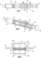
- Figures 1-3 show a first embodiment.
- the device comprises a syringe plunger 10 received in a syringe body 11.
- the plunger has a seal engagement flange 12 on one end thereof, and an operator engagement flange 13 on the other end thereof.
- a seal or sliding seal member (not illustrated), generally formed of a flexible organic polymer material (e . g ., rubber, thermoplastic elastomer (or "TPE”), etc.), is removably or permanently affixed to the seal engagement flange to force a liquid pharmaceutical formulation from the syringe body through the first (generally smaller) open end, or outlet port, 14, when the operator engagement flange is depressed.
- a flexible organic polymer material e . g ., rubber, thermoplastic elastomer (or "TPE", etc.
- the first open end or outlet port 14 may take any suitable form, such as a LEUER taper fitting, a LEUER-LOCK TM fitting, etc.
- the syringe body may include laterally extending finger or gripping tabs 15, which are optionally but preferably positioned near the second (wider) open end ( e.g., within 1 or 2 millimeters thereof).
- the plunger itself comprises a plunger shaft 20, which is formed of one or more plunger ribs 21 (four ribs in the embodiment of Figures 1-3 ).
- a disc-shaped plunger retention detent 22 is formed in a manner extending laterally from the plunger ribs, and positioned near the seal engagement flange, to help prevent the plunger itself from being inadvertently fully withdrawn from the syringe body when the plunger is retracted ( e.g., to draw a liquid pharmaceutical through the outlet port and into the syringe body for subsequent ejection therefrom).
- the disc-shaped retention detent 22 is configured to abut against a raised lip 23 formed on the inside wall of the syringe body near the second opening.
- the raised lip may take any suitable form, including a continuous ring, a ring interrupted ring interrupted by notches or gates, etc., and may have any suitable profile ( e.g., half-circle, triangular, rectangular, etc.).
- the plunger retention detent may take any suitable shape, including interrupted or uninterrupted shapes, and have any suitable profile.
- a first set of disc-shaped raised detents 30 is also provided on the plunger shaft, equally spaced along the length thereof, and configured to engage the raised lip.
- the detents are sufficiently large to cause perceptible, tactile, resistance to a human operator when the plunger is withdrawn from or depressed into the syringe body, but not so large as to prevent depression of the plunger into or withdrawal of the plunger from, the syringe body by the operator (optionally but preferably, with one-handed operation thereof).
- This first set of detents, while disc shaped like the plunger retention detent, may be shaped and/or sized differently therefrom, for example to provide lesser resistance to withdrawal than the plunger retention detent.
- Figures 4-5 illustrate a second embodiment, similar to the embodiment of Figures 1-3 , except that the set of detents are formed of discrete raised bumps 31 or segments on two of the four ribs, rather than as discs interconnecting the ribs.
- the raised detents on these two opposite ribs are aligned with one another so that they function together as a single set of detents, referred to as the first set of detents herein.
- Figure 6-7 illustrates a third embodiment, similar to the embodiment of Figures 4-5 , except that the first set of detents are not substantially rigid and laterally projecting (as in Figures 1-5 ), but instead comprises a set of flexible fingers 32 extending laterally from two oppositely facing ones of the four plunger ribs.
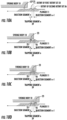
- Figures 8-9 illustrate a further embodiment having a first set of raised detents 33 formed on one rib thereof, and a second set of raised detents 36 formed on the opposite rib thereof.
- the first and second set of raised detents are equally spaced with, but slightly offset from, one another, to form a "trapping segment" 39 which retains the position of the syringe between each incremental injection segment.
- Figure 10A-10B are detailed illustrations of an embodiment similar to that of Figures 8-9 , except that the first and second set of detents 33, 36, are moved to the same rib, and a single member of each set is shown.
- the "trapping segment" 39 can be seen in between.
- the detents of the first set have a leading edge portion 34 and a trailing edge portion 35, with the slope of the trailing edge portion being greater (steeper) than the slope of the leading edge portion.
- the detents of the second set likewise have a leading edge portion 37 and a trailing edge portion 38, but in contrast the slope of the leading edge is greater (steeper) than the slope of the trailing edge.
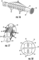
- Figures 16-18 illustrate an additional embodiment of the invention, including a first set of detents, where each detent is in the shape of a flexible leaf 41 extending from an elongate rib 21, which flexible leaf detents are flexed and released when they encounter the raised lip as the plunger is depressed into, or withdrawn from, the syringe body. Each leaf extends laterally from a side portion of one of the raised ribs (as more clearly seen in Figures 17-18 ) .
- the flexible leaf detents (which may be in the shape of, petals, lobes, etc.), may take any suitable form, as shown by the non-limiting additional examples set forth in Figures 19- 23.
- leaves optionally but preferably provide both an audible and tactile "click" to the user during operation of the syringe.
- the leaves are symmetrically shaped and symmetrically radially distributed around the plunger, to exert substantially uniform pressure on the lip 23, and syringe body, as they pass thereby.
- the edge portion of the leaf may be blunt, rounded, sharpened, etc., to tune the sound of the audible "click” created when each leaf (or leaf subset) is released by the lip 23.
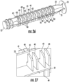
- Figures 24-25 illustrate a still further embodiment of the invention employing a first set of flexible leaf detents 41 and a second set of flexible leaf detents 43, with a "trapping segment" (like that described in connection with Figures 8-15 ) formed therebetween.
- This embodiment preferably provides both an audible and tactile "click" to the user both upon ending one incremental injection, and upon beginning the next incremental injection.
- Different leaf configurations are used for the first and second set of detents to provide a different resistance, and/or provide a different feel or sound to the click.
- Note an optional third set of fixed detents 49 is also included, as best seen in Figure 25 , and as discussed further in connection with Figures 26-27 below.
- Figures 26-27 illustrate a still further embodiment, similar to that of Figures 24-25 , except that the leaves of both the first and second set of flexible detents 41, 43 are similarly configured, and a third set of fixed detents 49 are also provided, aligned with the detents of the second set.
- This third set provides a greater resistance to overcome to leave a trapping segment and begin a next incremental injection, than required to enter the trapping segment upon entering the trapping segment.
- a tactile and/or audible click is provided both upon entering and exiting each trapping segment.
- the plunger or elongate shaft may comprise or consist of an organic polymer (e.g., polypropylene).
- the hollow body may comprise or consist of an organic polymer (e.g., polypropylene).
- the seal (not shown) may also be formed of an organic polymer, but generally a different material, that is elastic, such as natural or synthetic rubber or a thermoplastic elastomer (TPE).
- the syringe may having a total injectable volume of from 1 or 2 milliliters to 5, 10 or 30 milliliters, or more, with the first set of detents (and when present said second set of detents) configured to divide said total injectable volume into at least 5, 10 or 20 uniform injectable subvolumes, and up to 40 or 50 uniform injectable subvolumes.
- each of injectable subvolumes are not more than 1, 2, 5 or 10 percent different from one another.
- any of the foregoing syringes may be loaded with any suitable pharmaceutical formulation, such as a sterile injectable pharmaceutical formulation (e.g. a formulation comprising botulinum toxin or lidocaine in a pharmaceutically acceptable aqueous carrier) contained therein.
- a sterile injectable pharmaceutical formulation e.g. a formulation comprising botulinum toxin or lidocaine in a pharmaceutically acceptable aqueous carrier
- an injection needle (optionally with a removable or retractable cover to help minimize inadvertent "needle sticks”) may be fixed to or operatively associated with the outlet opening.
- a rigid or flexible endoscope e.g., a cystoscope
- guide cannula may be operatively coupled to the syringe outlet opening.
- syringe plunger may be provided as a subcombination part alone, useful for subsequent assembly into a complete syringe as described herein.
Claims (14)
- Seringue, comprenant :(a) un corps creux allongé (11) comportant une première extrémité ouverte (14), une paroi interne, une seconde extrémité ouverte et une lèvre annulaire relevée (23) sur ladite paroi interne ;(b) un piston de seringue (10) positionné dans ledit corps creux (11) à travers ladite seconde extrémité ouverte, ledit piston (10) comprenant :(i) une tige allongée (20) comportant un axe longitudinal, une partie d'extrémité supérieure et une partie d'extrémité inférieure ;(ii) un joint (12) relié à ladite partie d'extrémité inférieure ;(iii) une bride (13) reliée à ladite partie d'extrémité supérieure ; et(iv) un premier ensemble de crans (41) formés sur ladite tige allongée (20) selon un motif linéaire et uniformément espacé aligné avec ledit axe longitudinal,chaque élément dudit premier ensemble de crans (41) étant conçu pour se mettre en prise de manière séquentielle et libérable avec ladite lèvre (23) lorsque ledit piston (10) est retiré ou enfoncé dans ledit corps creux (11) ;ladite seringue comportant un volume total, ledit premier ensemble de crans étant conçu pour diviser ledit volume total en une pluralité de sous-volumes distincts,caractérisé en ce que chacun dudit premier ensemble de crans (41) comprend une feuille flexible ; etladite feuille flexible comprenant une charnière mobile reliant la feuille flexible à la tige allongée (20).
- Seringue selon la revendication 1, ladite tige allongée (20) comprenant au moins trois nervures allongées (21) jointes le long dudit axe longitudinal.
- Seringue selon la revendication 2, ledit premier ensemble de crans (41) étant formé sur au moins deux desdites nervures allongées (21).
- Seringue selon l'une quelconque des revendications 1 à 3, chaque cran dudit premier ensemble de crans (41) comprenant :
un cran relevé comportant une partie de bord d'attaque et une partie de bord de fuite, qui sont toutes deux alignées avec ledit axe longitudinal, une pente de ladite partie de bord de fuite dudit cran relevé étant supérieure à une pente de ladite partie de bord d'attaque du cran relevé :
un cran en retrait comportant une partie de bord d'attaque et une partie de bord de fuite, qui sont toutes deux alignées avec ledit axe longitudinal, une pente de ladite partie de bord de fuite dudit cran en retrait étant inférieure à une pente de ladite partie de bord d'attaque dudit cran en retrait. - Seringue selon l'une quelconque des revendications 1 à 4, comprenant en outre un deuxième ensemble de crans (43) formé sur ladite tige allongée (20) selon un motif linéaire et uniformément espacé aligné avec ledit axe longitudinal,
ledit deuxième ensemble de crans (43) étant positionné en alignement décalé avec ledit premier ensemble de crans (41), les premier et deuxième ensembles de crans étant conçus ensemble pour définir sur ladite tige allongée (20) : (i) une pluralité de segments d'injection de taille uniforme, et (ii) une pluralité de segments de piégeage (39) de taille uniforme en disposition alternée séquentielle avec lesdits segments d'injection. - Seringue selon la revendication 5, chaque cran dudit deuxième ensemble de crans (43) comprenant :un cran relevé comportant une partie de bord d'attaque et une partie de bord de fuite, toutes deux alignées avec ledit axe longitudinal, une pente de la partie de bord de fuite dudit cran relevé étant inférieure à une pente de ladite partie de bord d'attaque dudit cran relevé ; ouun cran en retrait comportant une partie de bord d'attaque et une partie de bord de fuite, toutes deux alignées avec ledit axe longitudinal, une pente de ladite partie de bord de fuite dudit cran en retrait étant supérieure à une pente de ladite partie de bord d'attaque dudit cran en retrait.
- Seringue selon l'une quelconque des revendications 1 à 6, ladite tige allongée (20) comprenant au moins une première et une seconde nervure allongée (21) jointes le long dudit axe longitudinal,ladite première nervure allongée (21) comprenant une paire de parties latérales opposées généralement plates et une partie de bord allongée,ledit premier ensemble de crans (41) comprenant une pluralité de feuilles flexibles s'étendant depuis au moins l'une desdites premières nervures allongées (21) opposées aux parties latérales.
- Seringue selon l'une quelconque des revendications 5 à 7, chaque élément dudit premier ensemble de crans (41), et dudit deuxième ensemble de crans (43) lorsqu'il est présent, comprenant à son tour un sous-ensemble de crans s'étendant latéralement depuis ladite tige allongée (20) dans le même plan, de sorte que les éléments dudit sous-ensemble exercent une pression dispersée, répartie radialement et/ou sensiblement uniforme contre ladite lèvre relevée (23) sur ladite paroi interne dudit cylindre (11), lorsque les éléments de ce sous-ensemble de crans (41, 43) rencontrent et dépassent ladite lèvre relevée (23).
- Seringue selon l'une quelconque des revendications 5 à 8, chacun desdits premier (41) et deuxième (43) ensembles de crans étant conçu pour fournir un clic audible et/ou tactile à un utilisateur lors du déplacement vers l'avant dudit piston (10) dans ledit cylindre (11), amenant chacun desdits crans ou sous-ensembles de crans à rencontrer et à dépasser ladite lèvre relevée (23).
- Seringue selon l'une quelconque des revendications 5 à 9, lesdits premier (41) et deuxième (43) ensembles de crans comprenant tous deux des crans à feuilles flexibles, ladite seringue comprenant en outre :
un troisième ensemble (49) de crans relevés fixes uniformément espacés formés sur ladite tige allongée (20) et positionnés pour aider à arrêter le déplacement vers l'avant dudit piston de seringue (10) juste après que chaque élément dudit deuxième ensemble de crans (43) ait déclenché un clic audible et/ou tactile au passage de ladite lèvre relevée (23). - Seringue selon l'une quelconque des revendications 1 à 10, ladite seringue comportant un volume injectable total de 1 ou 2 millilitres à 5 ou 10 millilitres, ledit premier ensemble de crans (41) étant conçu pour diviser ledit volume injectable total en au moins 10 ou 20 sous-volumes injectables uniformes, et jusqu'à 40 ou 50 sous-volumes injectables uniformes.
- Seringue selon l'une quelconque des revendications 1 à 11, comprenant en outre une formulation pharmaceutique injectable stérile contenue en son sein.
- Seringue selon l'une quelconque des revendications 1 à 12, ledit piston de seringue (20) étant libre et séparé du corps creux allongé (11), et conçu pour être inséré dans celui-ci.
- Seringue selon l'une quelconque des revendications 1 à 13, chaque élément du premier ensemble de crans (41) étant conçu pour se mettre en prise de manière séquentielle et libérable avec la lèvre (23) lorsque le piston (10) est retiré du corps creux allongé (11).
Applications Claiming Priority (2)
| Application Number | Priority Date | Filing Date | Title |
|---|---|---|---|
| US201462091248P | 2014-12-12 | 2014-12-12 | |
| PCT/US2015/065298 WO2016094828A1 (fr) | 2014-12-12 | 2015-12-11 | Seringue incrémentielle |
Publications (3)
| Publication Number | Publication Date |
|---|---|
| EP3229877A1 EP3229877A1 (fr) | 2017-10-18 |
| EP3229877A4 EP3229877A4 (fr) | 2018-08-08 |
| EP3229877B1 true EP3229877B1 (fr) | 2024-03-20 |
Family
ID=56108275
Family Applications (1)
| Application Number | Title | Priority Date | Filing Date |
|---|---|---|---|
| EP15866851.7A Active EP3229877B1 (fr) | 2014-12-12 | 2015-12-11 | Seringue incrémentielle |
Country Status (7)
| Country | Link |
|---|---|
| US (2) | US10398847B2 (fr) |
| EP (1) | EP3229877B1 (fr) |
| CN (1) | CN107206177B (fr) |
| AU (1) | AU2015360273B2 (fr) |
| BR (1) | BR112017012429B1 (fr) |
| CA (1) | CA2966369C (fr) |
| WO (1) | WO2016094828A1 (fr) |
Families Citing this family (24)
| Publication number | Priority date | Publication date | Assignee | Title |
|---|---|---|---|---|
| US8808246B2 (en) | 2009-07-21 | 2014-08-19 | The General Hospital Corporation | Peripheral blood sampling methods and devices |
| US10076272B2 (en) | 2011-04-26 | 2018-09-18 | Velano Vascular, Inc. | Systems and methods for phlebotomy through a peripheral IV catheter |
| US9186100B2 (en) | 2011-04-26 | 2015-11-17 | Velano Vascular, Inc. | Systems and methods for phlebotomy through a peripheral IV catheter |
| US8366685B2 (en) | 2011-04-26 | 2013-02-05 | Creative Vascular, Llc | Systems and methods for phlebotomy through a peripheral IV catheter |
| JP6177767B2 (ja) * | 2012-04-24 | 2017-08-09 | テルモ株式会社 | シリンジおよび装着具 |
| DE102015000999A1 (de) * | 2015-01-27 | 2016-07-28 | Sarl Omsi | Kolben für Spritzen und Spritzen |
| DE202016008940U1 (de) * | 2015-03-02 | 2020-11-30 | Fresenius Kabi Austria Gmbh | Kolbenstange mit wenigstens drei Ringelementen für eine vorgefüllte Spritze |
| US10300247B2 (en) * | 2016-02-03 | 2019-05-28 | Velano Vascular, Inc. | Devices and methods for fluid transfer through a placed peripheral intravenous catheter |
| US11090461B2 (en) | 2017-03-21 | 2021-08-17 | Velano Vascular, Inc. | Devices and methods for fluid transfer through a placed peripheral intravenous catheter |
| ES2921302T3 (es) | 2017-03-21 | 2022-08-23 | Velano Vascular Inc | Sistemas y métodos para controlar el tamaño de dispositivo de catéter |
| GB201707110D0 (en) * | 2017-05-04 | 2017-06-21 | Obrist Closures Switzerland | Dosing syringe |
| US10286159B2 (en) * | 2017-09-07 | 2019-05-14 | URO-1, Inc. | Medical injection assemblies for onabotulinumtoxina delivery and methods of use thereof |
| US10456164B2 (en) | 2017-10-02 | 2019-10-29 | URO-1, Inc. | Anti-microbial medical injection assemblies for onabotulinumtoxina delivery and methods of use thereof |
| US10463797B2 (en) * | 2017-09-07 | 2019-11-05 | URO-1, Inc. | Incremental syringe |
| SE542798C2 (en) * | 2018-04-06 | 2020-07-07 | Krui Ab | Auto disable prefilled syringe with plunger rod spring |
| US20210338936A1 (en) * | 2018-10-05 | 2021-11-04 | Amgen Inc. | Drug delivery device having dose indicator |
| KR102302552B1 (ko) * | 2019-03-13 | 2021-09-16 | (주)휴바이오메드 | 의료용 시린지 |
| US20200330688A1 (en) * | 2019-04-19 | 2020-10-22 | Merit Medical Systems, Inc. | Syringe with backpressure preventer and associated methods |
| US11878148B2 (en) | 2019-06-28 | 2024-01-23 | Becton, Dickinson And Company | Retaining element to prevent break loose contamination for partially pre-filled syringes |
| WO2021026352A1 (fr) * | 2019-08-07 | 2021-02-11 | Merit Medical Systems, Inc. | Seringue incrémentielle et systèmes et procédés associés |
| KR20220047837A (ko) | 2019-08-20 | 2022-04-19 | 벨라노 바스큘라, 인크. | 연장된 길이의 카테터를 가진 유체 이송 장치 및 이를 사용하는 방법 |
| EP4175701A1 (fr) | 2020-07-06 | 2023-05-10 | Alsahab Medical Company | Seringue à caractéristiques de rupture contrôlées |
| EP4251047A1 (fr) | 2020-11-26 | 2023-10-04 | Avia Vascular, LLC | Dispositifs, systèmes et procédés de prélèvement sanguin |
| WO2022235938A1 (fr) * | 2021-05-06 | 2022-11-10 | Covidien Lp | Seringue médicale |
Family Cites Families (35)
| Publication number | Priority date | Publication date | Assignee | Title |
|---|---|---|---|---|
| US288828A (en) | 1883-11-20 | Syringe | ||
| NL113374C (fr) | 1962-02-26 | 1966-11-15 | ||
| GB1225495A (fr) | 1967-06-15 | 1971-03-17 | ||
| US4654035A (en) * | 1985-09-12 | 1987-03-31 | Mitsubishi Pencil Co., Ltd. | Injector |
| US6090077A (en) | 1995-05-11 | 2000-07-18 | Shaw; Thomas J. | Syringe plunger assembly and barrel |
| US5722956A (en) | 1995-08-24 | 1998-03-03 | The General Hospital Corporation | Multi-dose syringe driver |
| US7862575B2 (en) | 2003-05-21 | 2011-01-04 | Yale University | Vascular ablation apparatus and method |
| US7860193B2 (en) * | 2004-07-20 | 2010-12-28 | Qualcomm Incorporated | Coarse timing estimation system and methodology for wireless symbols |
| US20080132852A1 (en) * | 2004-07-28 | 2008-06-05 | Kleyhan Gennady I | Dosage device |
| US20060161106A1 (en) * | 2004-11-09 | 2006-07-20 | Peng-Chieh Wu | Disposable retractable safety syringe having a hollow truncated cone with a slit |
| US7611495B1 (en) | 2005-10-07 | 2009-11-03 | Gianturco Michael C | Device for manually controlling delivery rate of a hypodermic syringe and syringe having same |
| AU2007296425B2 (en) | 2006-09-13 | 2014-01-23 | Merit Medical Systems, Inc. | Vascular treatment device |
| US8368725B1 (en) * | 2007-07-02 | 2013-02-05 | Rossella Limited | Laser scrolling color scheme for projection display |
| US9186464B2 (en) * | 2008-05-15 | 2015-11-17 | Allergan, Inc. | Dosing injector |
| US20090287161A1 (en) * | 2008-05-15 | 2009-11-19 | Allergan, Inc | Metered, multiple dose/aliquot syringe |
| US20100076370A1 (en) | 2008-09-23 | 2010-03-25 | Infusion Advancements, LLC. | Apparatus and methods for purging catheter systems |
| JP5717100B2 (ja) | 2009-02-20 | 2015-05-13 | コヴィディエン リミテッド パートナーシップ | 静脈不全の治療のための静脈閉鎖に対する装置 |
| DE102009014446B4 (de) * | 2009-03-23 | 2013-12-12 | Gilltec Gmbh | Auftrageinstrument für Dentalmassen und Auftrageeinheit |
| USD638123S1 (en) * | 2009-07-10 | 2011-05-17 | Becton, Dickinson And Company | Syringe plunger rod |
| CN102753275B (zh) * | 2010-02-12 | 2015-05-13 | 药物混合系统股份公司 | 具有锁止元件的排料装置 |
| WO2012012127A2 (fr) * | 2010-06-30 | 2012-01-26 | Hoyle John D Jr | Seringue de commande de dosage |
| CN101979108B (zh) * | 2010-09-09 | 2012-07-04 | 上海双鸽实业有限公司 | 胰岛素注射器 |
| EP2653484B1 (fr) * | 2010-12-27 | 2017-02-15 | Sumitomo Rubber Industries, Ltd. | Procédé de modification de surface, corps élastique modifié en surface, joint de seringue, seringue et pneu |
| EP2691133B1 (fr) * | 2011-03-28 | 2018-01-10 | Becton, Dickinson and Company | Bouchon en plastique |
| DE102011079682A1 (de) * | 2011-07-22 | 2013-01-24 | Transcodent GmbH & Co. KG | Auftragevorrichtung für Dentalmassen |
| FR2987746B1 (fr) * | 2012-03-08 | 2015-04-10 | Adip Sculpt | Seringue pour application medicale |
| WO2013156516A1 (fr) | 2012-04-19 | 2013-10-24 | Sanofi-Aventis Deutschland Gmbh | Ensemble pour dispositif d'administration de médicaments et dispositif d'administration de médicaments |
| CN104994897B (zh) * | 2013-01-30 | 2017-08-01 | S·T·阿姆斯特朗 | 注射器 |
| US20140288507A1 (en) * | 2013-03-24 | 2014-09-25 | Bensson Samuel | Self-Locking Syringe |
| EP3035903B1 (fr) | 2013-08-20 | 2018-08-22 | Anutra Medical, Inc. | Système de remplissage de seringue et procédé associé |
| EP2902061A1 (fr) * | 2014-01-30 | 2015-08-05 | Sanofi-Aventis Deutschland GmbH | Dispositifs d'administration de médicaments |
| CN110947050A (zh) * | 2014-01-31 | 2020-04-03 | 瓦莱里塔斯公司 | 用于流体传送装置的移动基础引擎 |
| MA41101A (fr) * | 2014-12-03 | 2017-10-10 | Lilly Co Eli | Dispositif d'injection de médicament automatique comportant une indication audible de progression d'injection |
| US9474864B2 (en) * | 2014-12-15 | 2016-10-25 | Brell Medical Innovations, LLC | Safety syringe and methods for administration of a medicament dose by subject weight |
| DE102015000999A1 (de) | 2015-01-27 | 2016-07-28 | Sarl Omsi | Kolben für Spritzen und Spritzen |
-
2015
- 2015-12-11 WO PCT/US2015/065298 patent/WO2016094828A1/fr active Application Filing
- 2015-12-11 CN CN201580063850.9A patent/CN107206177B/zh active Active
- 2015-12-11 BR BR112017012429-7A patent/BR112017012429B1/pt active IP Right Grant
- 2015-12-11 EP EP15866851.7A patent/EP3229877B1/fr active Active
- 2015-12-11 CA CA2966369A patent/CA2966369C/fr active Active
- 2015-12-11 US US14/966,326 patent/US10398847B2/en active Active
- 2015-12-11 AU AU2015360273A patent/AU2015360273B2/en active Active
-
2019
- 2019-08-30 US US16/557,696 patent/US11464913B2/en active Active
Also Published As
| Publication number | Publication date |
|---|---|
| AU2015360273A1 (en) | 2017-06-01 |
| US10398847B2 (en) | 2019-09-03 |
| US11464913B2 (en) | 2022-10-11 |
| CA2966369A1 (fr) | 2016-06-16 |
| AU2015360273B2 (en) | 2020-05-07 |
| EP3229877A1 (fr) | 2017-10-18 |
| CN107206177B (zh) | 2021-06-25 |
| CN107206177A (zh) | 2017-09-26 |
| US20200069881A1 (en) | 2020-03-05 |
| WO2016094828A1 (fr) | 2016-06-16 |
| CA2966369C (fr) | 2023-10-17 |
| BR112017012429A2 (pt) | 2018-01-02 |
| EP3229877A4 (fr) | 2018-08-08 |
| BR112017012429B1 (pt) | 2022-09-13 |
| US20160166772A1 (en) | 2016-06-16 |
Similar Documents
| Publication | Publication Date | Title |
|---|---|---|
| EP3229877B1 (fr) | Seringue incrémentielle | |
| JP6820104B2 (ja) | 多用途シリンジ基盤 | |
| JP7053709B2 (ja) | バイアル移送と注射の器具と方法 | |
| JP5819295B2 (ja) | 洗浄シリンジ組立体 | |
| KR920000464B1 (ko) | 일회용 주사기 | |
| KR920000439B1 (ko) | 일회용 주사기 | |
| US20080132852A1 (en) | Dosage device | |
| US20130253448A1 (en) | Hypodermic Needle With Multiple Dispersement Openings | |
| CN104185489B (zh) | 剂量指示器的末端 | |
| JP2023161010A (ja) | 注射器アセンブリ | |
| JP2023021444A (ja) | 高い投与量精度の薬物送達のためのシリンジプランジャーストッパー | |
| US11167089B2 (en) | Reduced sputtering syringe | |
| CN112512610A (zh) | 具有无菌内部的针头组件 | |
| US11648353B2 (en) | Incremental syringe and related systems and methods |
Legal Events
| Date | Code | Title | Description |
|---|---|---|---|
| STAA | Information on the status of an ep patent application or granted ep patent |
Free format text: STATUS: THE INTERNATIONAL PUBLICATION HAS BEEN MADE |
|
| PUAI | Public reference made under article 153(3) epc to a published international application that has entered the european phase |
Free format text: ORIGINAL CODE: 0009012 |
|
| STAA | Information on the status of an ep patent application or granted ep patent |
Free format text: STATUS: REQUEST FOR EXAMINATION WAS MADE |
|
| 17P | Request for examination filed |
Effective date: 20170616 |
|
| AK | Designated contracting states |
Kind code of ref document: A1 Designated state(s): AL AT BE BG CH CY CZ DE DK EE ES FI FR GB GR HR HU IE IS IT LI LT LU LV MC MK MT NL NO PL PT RO RS SE SI SK SM TR |
|
| AX | Request for extension of the european patent |
Extension state: BA ME |
|
| RIN1 | Information on inventor provided before grant (corrected) |
Inventor name: MIRZAZADEH, MAJID Inventor name: RUSSELL, KENNETH W. Inventor name: BROWN, PHILIP J. |
|
| DAV | Request for validation of the european patent (deleted) | ||
| DAX | Request for extension of the european patent (deleted) | ||
| A4 | Supplementary search report drawn up and despatched |
Effective date: 20180709 |
|
| RIC1 | Information provided on ipc code assigned before grant |
Ipc: A61M 5/315 20060101AFI20180703BHEP |
|
| STAA | Information on the status of an ep patent application or granted ep patent |
Free format text: STATUS: EXAMINATION IS IN PROGRESS |
|
| 17Q | First examination report despatched |
Effective date: 20210511 |
|
| STAA | Information on the status of an ep patent application or granted ep patent |
Free format text: STATUS: EXAMINATION IS IN PROGRESS |
|
| GRAP | Despatch of communication of intention to grant a patent |
Free format text: ORIGINAL CODE: EPIDOSNIGR1 |
|
| STAA | Information on the status of an ep patent application or granted ep patent |
Free format text: STATUS: GRANT OF PATENT IS INTENDED |
|
| INTG | Intention to grant announced |
Effective date: 20231025 |
|
| RIN1 | Information on inventor provided before grant (corrected) |
Inventor name: RUSSELL, KENNETH W. Inventor name: BROWN, PHILIP J. Inventor name: MIRZAZADEH, MAJID |
|
| GRAS | Grant fee paid |
Free format text: ORIGINAL CODE: EPIDOSNIGR3 |
|
| GRAA | (expected) grant |
Free format text: ORIGINAL CODE: 0009210 |
|
| STAA | Information on the status of an ep patent application or granted ep patent |
Free format text: STATUS: THE PATENT HAS BEEN GRANTED |
|
| P01 | Opt-out of the competence of the unified patent court (upc) registered |
Effective date: 20240205 |
|
| AK | Designated contracting states |
Kind code of ref document: B1 Designated state(s): AL AT BE BG CH CY CZ DE DK EE ES FI FR GB GR HR HU IE IS IT LI LT LU LV MC MK MT NL NO PL PT RO RS SE SI SK SM TR |
|
| REG | Reference to a national code |
Ref country code: GB Ref legal event code: FG4D |
|
| REG | Reference to a national code |
Ref country code: CH Ref legal event code: EP |
|
| REG | Reference to a national code |
Ref country code: DE Ref legal event code: R096 Ref document number: 602015088014 Country of ref document: DE |