EP3229109A1 - Jog dial for electronic device and electronic device provided with same - Google Patents
Jog dial for electronic device and electronic device provided with same Download PDFInfo
- Publication number
- EP3229109A1 EP3229109A1 EP15865265.1A EP15865265A EP3229109A1 EP 3229109 A1 EP3229109 A1 EP 3229109A1 EP 15865265 A EP15865265 A EP 15865265A EP 3229109 A1 EP3229109 A1 EP 3229109A1
- Authority
- EP
- European Patent Office
- Prior art keywords
- dial
- dial knob
- electronic device
- operation panel
- knob
- Prior art date
- Legal status (The legal status is an assumption and is not a legal conclusion. Google has not performed a legal analysis and makes no representation as to the accuracy of the status listed.)
- Granted
Links
- 238000004891 communication Methods 0.000 claims description 5
- 238000005406 washing Methods 0.000 description 44
- 101100480513 Caenorhabditis elegans tag-52 gene Proteins 0.000 description 5
- 230000008878 coupling Effects 0.000 description 3
- 238000010168 coupling process Methods 0.000 description 3
- 238000005859 coupling reaction Methods 0.000 description 3
- 238000010586 diagram Methods 0.000 description 2
- 230000004048 modification Effects 0.000 description 2
- 238000012986 modification Methods 0.000 description 2
- 230000035515 penetration Effects 0.000 description 2
- 230000008901 benefit Effects 0.000 description 1
- 230000008859 change Effects 0.000 description 1
- 230000006870 function Effects 0.000 description 1
- 230000005358 geomagnetic field Effects 0.000 description 1
- 210000002268 wool Anatomy 0.000 description 1
Images


Classifications
-
- G—PHYSICS
- G06—COMPUTING; CALCULATING OR COUNTING
- G06F—ELECTRIC DIGITAL DATA PROCESSING
- G06F3/00—Input arrangements for transferring data to be processed into a form capable of being handled by the computer; Output arrangements for transferring data from processing unit to output unit, e.g. interface arrangements
- G06F3/01—Input arrangements or combined input and output arrangements for interaction between user and computer
- G06F3/02—Input arrangements using manually operated switches, e.g. using keyboards or dials
-
- G—PHYSICS
- G06—COMPUTING; CALCULATING OR COUNTING
- G06F—ELECTRIC DIGITAL DATA PROCESSING
- G06F3/00—Input arrangements for transferring data to be processed into a form capable of being handled by the computer; Output arrangements for transferring data from processing unit to output unit, e.g. interface arrangements
- G06F3/01—Input arrangements or combined input and output arrangements for interaction between user and computer
- G06F3/03—Arrangements for converting the position or the displacement of a member into a coded form
- G06F3/033—Pointing devices displaced or positioned by the user, e.g. mice, trackballs, pens or joysticks; Accessories therefor
- G06F3/0362—Pointing devices displaced or positioned by the user, e.g. mice, trackballs, pens or joysticks; Accessories therefor with detection of 1D translations or rotations of an operating part of the device, e.g. scroll wheels, sliders, knobs, rollers or belts
-
- G—PHYSICS
- G05—CONTROLLING; REGULATING
- G05G—CONTROL DEVICES OR SYSTEMS INSOFAR AS CHARACTERISED BY MECHANICAL FEATURES ONLY
- G05G1/00—Controlling members, e.g. knobs or handles; Assemblies or arrangements thereof; Indicating position of controlling members
- G05G1/08—Controlling members for hand actuation by rotary movement, e.g. hand wheels
-
- G—PHYSICS
- G06—COMPUTING; CALCULATING OR COUNTING
- G06F—ELECTRIC DIGITAL DATA PROCESSING
- G06F3/00—Input arrangements for transferring data to be processed into a form capable of being handled by the computer; Output arrangements for transferring data from processing unit to output unit, e.g. interface arrangements
- G06F3/01—Input arrangements or combined input and output arrangements for interaction between user and computer
- G06F3/02—Input arrangements using manually operated switches, e.g. using keyboards or dials
- G06F3/0202—Constructional details or processes of manufacture of the input device
- G06F3/0205—Lever arrangements for operating keyboard cursor control keys in a joystick-like manner
-
- H—ELECTRICITY
- H01—ELECTRIC ELEMENTS
- H01H—ELECTRIC SWITCHES; RELAYS; SELECTORS; EMERGENCY PROTECTIVE DEVICES
- H01H19/00—Switches operated by an operating part which is rotatable about a longitudinal axis thereof and which is acted upon directly by a solid body external to the switch, e.g. by a hand
- H01H19/02—Details
- H01H19/10—Movable parts; Contacts mounted thereon
- H01H19/14—Operating parts, e.g. turn knob
-
- H—ELECTRICITY
- H01—ELECTRIC ELEMENTS
- H01H—ELECTRIC SWITCHES; RELAYS; SELECTORS; EMERGENCY PROTECTIVE DEVICES
- H01H3/00—Mechanisms for operating contacts
- H01H3/02—Operating parts, i.e. for operating driving mechanism by a mechanical force external to the switch
- H01H3/0213—Combined operation of electric switch and variable impedance, e.g. resistor, capacitor
-
- H—ELECTRICITY
- H01—ELECTRIC ELEMENTS
- H01H—ELECTRIC SWITCHES; RELAYS; SELECTORS; EMERGENCY PROTECTIVE DEVICES
- H01H3/00—Mechanisms for operating contacts
- H01H3/02—Operating parts, i.e. for operating driving mechanism by a mechanical force external to the switch
- H01H3/08—Turn knobs
Definitions
- the present disclosure relates to a jog dial used in an electronic device. More particularly, the present disclosure relates to a jog dial for an electronic device having a structure in which a rotary dial and a detector for detecting a position of the rotary dial are separated from each other, and an electronic device provided with the same.
- Electronic devices such as a washing machine use a jog dial to allow a user to select a desired course from various work courses that the electronic device can perform.
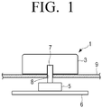
- FIG. 1 An example of a conventional jog dial used in the electronic devices is illustrated in FIG. 1 .
- the conventional jog dial 1 includes a dial knob 3 and a potential meter 5.
- the potential meter 5 is provided on a circuit board 6 for controlling an electronic device, and the circuit board 6 is disposed below an operation panel 9 provided in a case of the electronic device. Therefore, the potential meter 5 is located below the operation panel 9.
- a rotating shaft 7 coupled with the dial knob 3 is provided at the center of the potential meter 5. The rotating shaft 7 of the potential meter 5 passes through the operation panel 9 of the electronic device and protrudes upward.
- the dial knob 3 is coupled to the rotating shaft 7 of the potential meter 5 above the operation panel 9 of the electronic device. Accordingly, when the user turns the dial knob 3, the rotating shaft 7 coupled to the dial knob 3 is rotated.
- a controller of the circuit board 6 may recognize a position of the dial knob 3 by receiving the value output from the potential meter 5. Accordingly, if the values output from the potential meter 5 are matched with various work courses that can be performed by the electronic device, the user may select a desired work course by rotating the dial knob 3.
- the conventional jog dial 1 is provided with the dial knob 3 and the potential meter 5 which are mechanically coupled to each other, when the jog dial 1 is aged, the dial knob 3 may not rotate smoothly, or the connection portion between the dial knob 3 and the rotating shaft 7 may be broken.
- the operation panel 9 of the electronic device is provided with a through hole 8 through which the rotating shaft 7 of the potential meter 5 passes, there is a problem that the circuit board 6 may be damaged by moisture that enters into the inside of the operation panel 9 through the through hole 8.
- the conventional jog dial 1 since the conventional jog dial 1 has a structure in which the dial knob 3 and the rotating shaft 7 of the potential meter 5 are mechanically coupled to each other, there is a design limitation that the dial knob 3 must have a certain height or more for the coupling of the dial knob 3 and the rotating shaft 7. Accordingly, there is a problem that the conventional jog dial 1 itself becomes a restriction factor in the design of the electronic device.
- the present disclosure has been developed in order to overcome the above drawbacks and other problems associated with the conventional arrangement, and relates to a jog dial that can minimize a failure due to mechanical coupling and prevent moisture penetration because a dial knob and a detector for detecting the positions of the dial knob are separated from each other without being mechanically connected, and an electronic device having the same.
- a jog dial for an electronic device used in an electronic device with an operation panel may include a dial knob rotatably disposed in an upper surface of the operation panel; a body to be detected provided with the dial knob; and a detector disposed below the operation panel and configured to identify the body to be detected and output a signal, wherein the dial knob and the detector are separated from each other.
- the body to be detected may include a permanent magnet, and the detector may include a geomagnetic sensor.
- the geomagnetic sensor may be disposed below a rotation center of the dial knob, and the permanent magnet may be disposed at a position eccentric from the rotation center of the dial knob.
- the body to be detected may include a plurality of near field communication (NFC) tags, and the detector may include an NFC reader.
- NFC near field communication
- the plurality of NFC reader may be provided in the dial knob in a circular shape centered on a rotation center of the dial knob, and the NFC reader may be provided to read one NFC tag among the plurality of NFC tags.
- the operation panel may be provided with a rotation protrusion
- the dial knob is provided with a rotation groove into which the rotation protrusion is inserted, wherein when the rotation protrusion of the operation panel is inserted into the rotation groove of the dial knob, the dial knob is rotatable with respect to the operation panel.
- the operation panel may be provided with a rotation groove, and a lower surface of the dial knob may be provided with a rotation protrusion which is inserted into the rotation groove, wherein when the rotation protrusion of the dial knob is inserted into the rotation groove of the operation panel, the dial knob is rotatable with respect to the operation panel.
- the operation panel may be provided with a dial groove into which the dial knob is inserted, and the dial knob may be rotatably disposed in the dial groove.
- the dial knob may be formed in a ring shape, and the operation panel may be provided with an annular groove into which the dial knob of the ring shape is inserted, wherein the dial knob of the ring shape is rotatably disposed in the annular groove.
- a display may be provided in a central portion of the annular groove of the operation panel.
- the dial knob may be formed in a ring shape, and a circular support portion which is inserted into the dial knob of the ring shape may protrude from the operation panel, wherein the dial knob of the ring shape is rotatably supported by the circular support portion.
- a display may be provided in the circular support portion of the operation panel.
- an electronic device may include a case for the electronic device; an operation panel provided in the case; a dial knob rotatably disposed in a upper surface of the operation panel; a body to be detected disposed in the dial knob; a circuit board disposed below the operation panel and provided with a detector that identifies the body to be detected and outputs a signal; and a controller disposed in the circuit board, and configured to control the electronic device using the signal of the detector, wherein the dial knob and the detector are separated from each other and the operation panel is interposed between the dial knob and the detector.
- the controller may include a lookup table defining positions of the body to be detected and operations of the electronic device.
- the body to be detected may include a permanent magnet or a plurality of NFC tags, and the detector may include a geomagnetic sensor or an NFC reader.
- the geomagnetic sensor may be disposed below a rotation center of the dial knob, and the permanent magnet may be disposed at a position eccentric from the rotation center of the dial knob.
- the plurality of NFC reader may be provided in the dial knob in a circular shape centered on a rotation center of the dial knob, and the NFC reader may be provided to communicate with one NFC tag among the plurality of NFC tags.
- the electronic device may include a washing machine and a microwave oven.
- FIG. 2a is a perspective view illustrating a jog dial for an electronic device according to an embodiment of the present disclosure
- FIG. 2b is a cross-sectional view illustrating the jog dial of FIG. 2a taken along a line A-A
- FIG. 2c is an exploded perspective view illustrating the jog dial of FIG. 2a .
- a case of an electronic device in which a jog dial according to the present disclosure is disposed is provided with an operation panel on which the jog dial may be disposed.
- the operation panel of the electronic device may be provided with various buttons, switches, a display, and the like in addition to the jog dial so that a user may control the electronic device using the operation panel.
- the jog dial according to the present disclosure may be used in electronic devices such as a washing machine, a microwave oven, and the like.
- a jog dial 10 for an electronic device may include a dial knob 11 and a detector 15.
- the dial knob 11 is a substantially disc shape, and is rotatably disposed on the upper surface of the operation panel 19 of the electronic device.
- a rotation protrusion 18 is formed on the upper surface of the operation panel 19 of the electronic device, and a rotation groove 13 into which the rotation protrusion 18 of the operation panel 19 may be inserted is formed in the lower surface of the dial knob 11.
- the rotation protrusion 18 of the operation panel 19 and the rotation groove 13 of the dial knob 11 are formed such that the dial knob 11 is free to rotate with respect to the rotation protrusion 18 and does not come off from the rotation protrusion 18.
- the dial knob 11 is formed to maintain its position when the applied force is removed. Accordingly, when the rotation protrusion 18 of the operation panel 19 is inserted into the rotation groove 13 of the dial knob 11, the dial knob 11 may stably freely rotate above the operation panel 19.
- the dial knob 11 is provided with a body to be detected 12 for allowing the detector 15 to recognize the position of the dial knob 11.
- the body to be detected 12 is disposed so that the position of the body to be detected 12 changes as the dial knob 11 rotates.
- the body to be detected 12 may be provided on the upper surface of the dial knob 11. However, it is preferable that the body to be detected 12 is provided on the lower surface of the dial knob 11 so that the detector 15 provided under the operation panel 19 can easily detect the body to be detected 12.
- Various types of the body to be detected 12 may be used depending on the type of the detector 15. For example, when a geomagnetic sensor is used as the detector 15, a permanent magnet may be used as the body to be detected 12. Alternatively, in the case where a near field communication (NFC) reader is used as the detector 15, an NFC tag may be used as the body to be detected 12.
- NFC near field communication
- the body to be detected 12 is provided at a position eccentric from the center of the rotation of the dial knob 11. Accordingly, when the dial knob 11 is rotated, the position of the body to be detected 12 changes, and the detector 15 recognizes the position of the body to be detected 12 at this time and outputs a signal corresponding to the position of the body to be detected 12.
- the detector 15 detects the body to be detected 12 and outputs a signal.
- the detector 15 is provided below the operation panel 19 of the case of the electronic device.
- the detector 15 may be disposed on a circuit board 17 provided below the operation panel 19 and may not be exposed to the outside.
- the detector 15 and the dial knob 11 are not mechanically coupled to each other.
- the detector 15 is disposed at a predetermined distance away from the dial knob 11. That is, the detector 15 are not mechanically connected to and are separated from the dial knob 11. Accordingly, no force is applied to the detector 15 even when the dial knob 11 rotates.
- the circuit board 17 may include a controller for controlling the operation of the electronic device, and may be composed of a central processing unit (CPU), a memory, and various electronic components constituting an electronic circuit.
- CPU central processing unit
- FIGS. 2a , 2b , and 2c show a case where the body to be detected 12 disposed on the dial knob 11 is a permanent magnet and the detector 15 provided on the circuit board 17 is a geomagnetic sensor.
- the geomagnetic sensor used as the detector 15 outputs information on the north direction by detecting geomagnetic field, and is widely used in smartphones and the like.
- the geomagnetic sensor 15 detects the magnetic field of the permanent magnet 12 and outputs information about the position of the permanent magnet 12. Accordingly, when the position of the permanent magnet 12 is changed by rotating the dial knob 11, the value output from the geomagnetic sensor 15 changes.
- a controller which is electrically connected to the geomagnetic sensor 15, may identify the position of the permanent magnet 12 by reading the output value.
- the geomagnetic sensor 15 is disposed below the rotation center of the dial knob 11. That is, the geomagnetic sensor 15 is disposed so that the center line CL passing through the rotation center of the dial knob 11 passes through the center of the geomagnetic sensor 15. Therefore, when the dial knob 11 provided with the permanent magnet 12 eccentrically about the rotation center of the dial knob 11 rotates, the geomagnetic sensor 15 may detect and output the position of the permanent magnet 12 which changes along the locus of the circle around the center line CL.
- the dial knob 11 and the detector 15 of the jog dial 10 according to the present disclosure are not mechanically connected to each other, the dial knob 11 may be formed in various shapes.
- various examples of the dial knob used in the jog dial 10 according to an embodiment of the present disclosure will be described in detail with reference to FIGS. 3 to 7b .
- FIGS. 2a to 2c illustrate the case where the rotation groove 13 is formed in the lower surface of the dial knob 11, and the rotation protrusion 18 is formed in the operation panel 19 of the electronic device
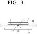
- the reverse may be also possible. That is, as illustrated in FIG. 3 , a rotation protrusion 13' is formed on the lower surface of the dial knob 11, and a rotation groove 18' into which the rotation protrusion 13' is inserted is formed on the operation panel 19 of the electronic device.
- the rotation groove 18' is formed in the operation panel 19, there is an advantage that the thickness of the dial knob 11 may be made thinner than the dial knob 11 according to the above-described embodiment.
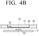
- FIGS. 4a and 4b illustrate the case where the dial knob is embedded in the operation panel 19 of the electronic device.
- an operation panel 29 of an electronic device is provided with a dial groove 28 corresponding to the shape and size of a dial knob 21 into which a dial knob 21 is inserted.
- the dial groove 28 is formed such that the dial knob 21 is inserted and freely rotatable. Therefore, the dial knob 21 provided in the dial groove 28 may be freely rotated with respect to the dial groove 28 when the user rotates the dial knob 21 by applying a force to the dial knob 21. When the user does not apply a force to the dial knob 21, the dial knob 21 may maintain the current position.
- the permanent magnet 12 of the body to be detected is disposed on the lower surface of the dial knob 21 in the same manner as in the above-described embodiment, and the geomagnetic sensor 15 as a detector for detecting the permanent magnet 12 is disposed on the circuit board 17 below the operation panel 29.
- the geomagnetic sensor 15 is disposed so that the center of the geomagnetic sensor 15 coincides with the rotation center of the dial knob 21. That is, the center of the geomagnetic sensor 15 and the rotation center of the dial knob 21 are located on the same center line CL.
- FIG. 4b illustrates a case where no rotation protrusion is provided on either the dial knob 21 or the operation panel 29.
- the lower surface of the dial knob 21 may be provided with a rotation protrusion as illustrated in FIG. 2b or a rotation groove as illustrated in FIG. 3 .
- the dial groove 28 of the operation panel 29 into which the dial knob 21 is inserted may be provided with a rotation groove corresponding to the rotation protrusion of the dial knob 21 or a rotation protrusion corresponding to the rotation groove of the dial knob 21.
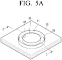
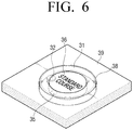
- FIGS. 5a and 5b show a case where a dial knob is formed in a ring shape and is embedded in an operation panel of the electronic device.
- a dial knob 31 is formed in a ring (annulus) shape.
- a permanent magnet 32 of the body to be detected may be disposed on the lower surface of the dial knob 31 of the ring shape.
- An operation panel 39 of the electronic device is provided with an annular groove 38 into which the dial knob 31 of the ring shape is inserted.
- the annular groove 38 is formed such that the dial knob 31 of the ring shape is inserted and freely rotatable. Accordingly, the dial knob 31 of the ring shape provided in the annular groove 38 may be freely rotated with respect to the annular groove 38 when the user rotates the dial knob 31 by applying a force to the dial knob 31.
- the dial knob 31 may maintain the current position.
- the upper surface of the dial knob 31 may be provided with a contact groove 35 having a concave shape, which may be contacted with the user's fingertip, so that the user can rotate the dial knob 31 easily.
- a contact groove 35 is illustrated in FIG. 6 .
- the geomagnetic sensor 15 as a detector for detecting the permanent magnet 32 of the body to be detected 12 is disposed on the circuit board 17 provided below the operation panel 39 in the same manner as in the above-described embodiment. Also, the geomagnetic sensor 15 is disposed so that the center of the geomagnetic sensor 15 coincides with the rotation center of the dial knob 31 of the ring shape. That is, the center of the geomagnetic sensor 15 and the rotation center of the dial knob 31 are located on the same center line CL.
- a display 36 may be provided in a central portion 37 of the annular groove 38 of the operation panel 39 of the electronic device.
- a case in which the display 36 is provided in the central portion 37 of the annular groove 38 is illustrated in FIG. 6 .
- the display 36 may display a description of the operation selected by the rotation of the dial knob 31.
- the display 36 may be configured to display a description of the standard course as illustrated in FIG. 6 .
- the display 36 may display a detailed description of the standard course.
- a flat panel display such as an LCD, an OLED, and the like may be used as the display 36.
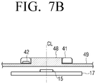
- FIGS. 7a and 7b illustrate a case in which a dial knob is formed in a ring (annular) shape, and protruded from an operation panel of the electronic device.
- a dial knob 41 is formed in a ring (annulus) shape.
- a permanent magnet 42 of the body to be detected may be disposed on the lower surface of the dial knob 41 of the ring shape.
- An operation panel 49 of the electronic device is provided with a circular support portion 48 which is inserted into the dial knob 41 of the ring shape.
- the circular support portion 48 is formed in a cylindrical shape protruding from the operation panel 49, and the protruding height thereof may be formed to be substantially equal to the thickness of the dial knob 41. Further, the circular support portion 48 is formed so that the dial knob 41 of the ring shape is inserted and freely rotatable.
- the dial knob 41 of the ring shape provided in the circular support portion 48 of the operation panel 49 may be freely rotated with respect to the circular support portion 48 when the user rotates the dial knob 41 by applying a force to the dial knob 41.
- the dial knob 41 may maintain the current position.
- the circular support portion 48 may be provided with a display in the same manner as the embodiment of the dial knob 31 illustrated in FIG. 6 .
- the display may display a description of the operation selected by the rotation of the dial knob 41 as in the above-described embodiment.
- a jog dial in which an NFC reader (near field communication reader) is used as a detector and an NFC tag (near field communication tag) is used as a body to be detected will be described in detail with reference to FIGS. 8a to 8c .
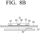
- FIG. 8a is a plan view illustrating a jog dial for an electronic device according to another embodiment of the present disclosure
- FIG. 8b is a cross-sectional view illustrating the jog dial of FIG. 8a taken along a line E-E
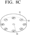
- FIG. 8c is a rear perspective view illustrating a dial knob of the jog dial of FIG. 8a .
- a jog dial 50 may include a dial knob 51 and an NFC reader 55.
- the dial knob 51 is rotatably disposed on the upper surface of the operation panel 59 of the electronic device.
- a rotation protrusion 58 is formed on the upper surface of the operation panel 59 of the electronic device, and a rotation groove 53 into which the rotation protrusion 58 of the operation panel 59 is inserted is formed on the lower surface of the dial knob 51.
- the rotation protrusion 58 of the operation panel 59 and the rotation groove 53 of the dial knob 51 are formed such that the dial knob 51 is freely rotatable with respect to the rotation protrusion 58 and does not come off from the rotation protrusion 58.
- the dial knob 51 is formed to maintain its position when the applied force is removed. Accordingly, when the rotation protrusion 58 of the operation panel 59 is inserted into the rotation groove 53 of the dial knob 51, the dial knob 51 may be stably freely rotated above the operation panel 59.
- a plurality of NFC tags 52 is provided on the lower surface of the dial knob 51.
- the plurality of NFC tags 52 is arranged to form one circle centered on the rotation center of the dial knob 51.
- the plurality of NFC tags 52 may be formed to have different codes, respectively. For example, when eight NFC tags 52 are used, NFC tags 52 having codes of 1 to 8 are arranged in order on the lower surface of the dial knob 51 as illustrated in FIG. 8c .
- the plurality of NFC tags 52 may be formed by sequentially arranging NFC tags 52 having two different codes. For example, when eight NFC tags 52 are used, four NFC tags 52 having a code of 1 and four NFC tags 52 having a code of 2 are arranged as 1-2-1-2-1-2-1-2 on the lower surface of the dial knob 51.
- the NFC reader 55 serving as a detector of the NFC tag 52 is provided on a circuit board 57 disposed below the operation panel 59 to be able to communicate with and recognize the NFC tags 52 disposed on the lower surface of the dial knob 51.
- the NFC reader 55 may include an NFC antenna (not illustrated) to communicate with the NFC tags 52 and to read information recorded in the NFC tags 52.
- the NFC reader 55 is disposed to read only one NFC tag 52 among the plurality of NFC tags 52 provided on the dial knob 51 as illustrated in FIG. 8a .
- the NFC reader 55 is disposed not to be mechanically coupled to the dial knob 51. In other words, because the NFC reader 55 is disposed at a certain distance apart from and not in contact with the dial knob 51, the NFC reader 55 and the dial knob 51 are not mechanically connected to, but are separated from each other.
- the NFC reader 55 communicates with the NFC tag 52 located directly above the NFC reader 55 among the plurality of NFC tags 52 attached to the dial knob 51, reads the value stored in the corresponding NFC tag 52, and outputs the value. Then, the controller 110 connected to the NFC reader 55 may recognize the current position of the dial knob 51 based on the output value of the NFC reader 55.
- the shape of the dial knob 51 may be formed in various shapes like the above-described jog dial 10 using the geomagnetic sensor 15. That is, the dial knob 51 of the jog dial 50 according to the present embodiment may be formed in the shapes as illustrated in FIGS. 3 to 7b .
- the plurality of NFC tags 52 is provided on the lower surface of the dial knob 51 and the NFC reader 55 is disposed just below one NFC tag 52 of the plurality of NFC tags 52 provided on the dial knob 51 instead of the rotation center of the dial knob 51.
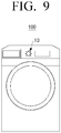
- FIG. 9 is a view illustrating a washing machine to which a jog dial for an electronic device according to an embodiment of the present disclosure is applied
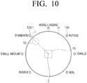
- FIG. 10 is an enlarged view illustrating a portion of the washing machine of FIG. 9 where the jog dial is disposed
- FIG. 11 is a functional block diagram illustrating a relationship between the jog dial and a controller in the washing machine of FIG. 9 .
- a jog dial 10 is provided on an operation panel of a washing machine 100 so that the user can select one of several washing courses.
- the washing machine 100 may be provided with washing courses such as boil, towels, futons, wool/lingerie, standard, a small amount, and bubble courses. Accordingly, the user may select one of the several washing courses with the jog dial 10 according to an embodiment of the present disclosure.
- the several washing courses are arranged at a predetermined interval around the dial knob 51 of the jog dial 10 of the washing machine 100, and each of the washing courses is provided with a light emitting diode (LED) 120 that lights up when the washing course is selected.
- LED light emitting diode
- the jog dial 10 is formed in the same manner as the jog dial 10 illustrated in FIGS. 2a to 2c .
- a permanent magnet 12 is provided on the lower surface of the dial knob 11 and a circuit board 17 provided with a geomagnetic sensor 15 serving as a detector is provided below the operation panel 19 in which the dial knob 11 is disposed (see FIG. 2b ).
- the circuit board 17 may include a controller 110 that controls the washing machine 100 to perform various washing courses.
- the position of the permanent magnet 12 changes, and the geomagnetic sensor 15 recognizes the changing position of the permanent magnet 12 and outputs a signal relating to the position of the permanent magnet 12.
- the controller 110 of the circuit board 17 connected to the geomagnetic sensor 15 identifies the position of the permanent magnet 12 using the signal output from the geomagnetic sensor 15. For example, when the geomagnetic sensor 15 outputs pulses of the X, Y, and Z directions with respect to a change in the position of the permanent magnet 12, the controller 110 may identify the position of the permanent magnet 12 by counting the pulses output from the geomagnetic sensor 15.
- a lookup table 112 in which the relationship between the positions of the permanent magnet 12 of the dial knob 11 and the washing courses is recorded may be stored in the controller 110.
- the lookup table 112 the relationship between the washing courses and the positions of the permanent magnet 12 in the XY coordinate system with the rotation center C of the dial knob 11 as the origin may be recorded. That is, the coordinates of the permanent magnet 12 when the permanent magnet 12 is positioned on the straight line L connecting an LED 120 that is illuminated as the washing course is selected and the rotation center C of the dial knob 11 may be matched with a washing course. For example, when the permanent magnet 12 is positioned on the straight line L connecting the LED 120-1 representing the standard washing course and the rotation center C of the dial knob 11 in FIG.
- the washing machine 100 having seven washing courses as illustrated in FIG. 10 may be provided with the lookup table 112 in which seven coordinates and seven washing courses are matched.
- the controller 110 identifies the position of the permanent magnet 12 using the output signal of the geomagnetic sensor 15.
- the controller 110 turns on the LED 120 of the washing course corresponding to the coordinates.
- the controller 110 determines that the permanent magnet 12 is at the coordinates (a, b) from the output signal of the geomagnetic sensor 15, turns on the LED 120-1 representing the standard washing course, and recognizes that the standard washing course is selected by the user.
- the controller 110 controls the washing machine 100 to perform washing with the standard washing course selected by the jog dial 10.
- the geomagnetic sensor 15 is used as the detector, and the permanent magnet 12 is used as the body to be detected.
- the operation of selecting the washing course is the same as described above.
- the detector that provides the information received by the controller 110 is different as the geomagnetic sensor 15 and the NFC reader 55.
- the NFC reader 55 there are restrictions on the number of NFC tags 52 that are the reference for identifying the position and the number of washing courses to be selected. That is, the number of NFC tags 52 is greater than the number of washing courses to be selected. Therefore, when there are seven washing courses as illustrated in FIG. 10 , the number of NFC tags 52 may be eight or more.
- the washing machine 100 has been described as an example of the electronic device to which the jog dials 10 and 50 according to an embodiment of the present disclosure are applied.
- the electronic device to which the jog dials 10 and 50 according to the present disclosure are applied is not limited thereto.
- the jog dials 10 and 50 according to the present disclosure may be applied to electronic devices using the conventional jog dial like a microwave oven.
- FIG. 12 is a view illustrating a microwave oven to which a jog dial for an electronic device according to an embodiment of the present disclosure is applied.
- the jog dial 10 may be used as a manual dial for the microwave oven 200.
- the rotating dial knob and the detector for detecting the body to be detected provided on the dial knob are separated from each other without being mechanically connected, a failure due to mechanical coupling may be minimized and damage of the circuit board due to moisture penetration may be prevented.
Abstract
invention comprises: a dial knob rotatably provided on an upper surface of an operation panel of the electronic device; an object
provided on the dial knob; and a detector provided below the operation panel, and detecting the object so as to output a signal,
Description
- The present disclosure relates to a jog dial used in an electronic device. More particularly, the present disclosure relates to a jog dial for an electronic device having a structure in which a rotary dial and a detector for detecting a position of the rotary dial are separated from each other, and an electronic device provided with the same.
- Electronic devices such as a washing machine use a jog dial to allow a user to select a desired course from various work courses that the electronic device can perform.
- An example of a conventional jog dial used in the electronic devices is illustrated in
FIG. 1 . - Referring to
FIG. 1 , the conventional jog dial 1 includes adial knob 3 and apotential meter 5. Thepotential meter 5 is provided on acircuit board 6 for controlling an electronic device, and thecircuit board 6 is disposed below anoperation panel 9 provided in a case of the electronic device. Therefore, thepotential meter 5 is located below theoperation panel 9. Also, a rotatingshaft 7 coupled with thedial knob 3 is provided at the center of thepotential meter 5. The rotatingshaft 7 of thepotential meter 5 passes through theoperation panel 9 of the electronic device and protrudes upward. Thedial knob 3 is coupled to the rotatingshaft 7 of thepotential meter 5 above theoperation panel 9 of the electronic device. Accordingly, when the user turns thedial knob 3, therotating shaft 7 coupled to thedial knob 3 is rotated. When the rotatingshaft 7 rotates, a value output from thepotential meter 5 changes. A controller of thecircuit board 6 may recognize a position of thedial knob 3 by receiving the value output from thepotential meter 5. Accordingly, if the values output from thepotential meter 5 are matched with various work courses that can be performed by the electronic device, the user may select a desired work course by rotating thedial knob 3. - However, since the conventional jog dial 1 is provided with the
dial knob 3 and thepotential meter 5 which are mechanically coupled to each other, when the jog dial 1 is aged, thedial knob 3 may not rotate smoothly, or the connection portion between thedial knob 3 and therotating shaft 7 may be broken. - In addition, when the
potential meter 5 is aged, there is a problem that thepotential meter 5 may be damaged or a recognition error may occur. - Also, since the
operation panel 9 of the electronic device is provided with athrough hole 8 through which therotating shaft 7 of thepotential meter 5 passes, there is a problem that thecircuit board 6 may be damaged by moisture that enters into the inside of theoperation panel 9 through the throughhole 8. - In addition, since the conventional jog dial 1 has a structure in which the
dial knob 3 and therotating shaft 7 of thepotential meter 5 are mechanically coupled to each other, there is a design limitation that thedial knob 3 must have a certain height or more for the coupling of thedial knob 3 and therotating shaft 7. Accordingly, there is a problem that the conventional jog dial 1 itself becomes a restriction factor in the design of the electronic device. - The present disclosure has been developed in order to overcome the above drawbacks and other problems associated with the conventional arrangement, and relates to a jog dial that can minimize a failure due to mechanical coupling and prevent moisture penetration because a dial knob and a detector for detecting the positions of the dial knob are separated from each other without being mechanically connected, and an electronic device having the same.
- According to an aspect of the present disclosure, a jog dial for an electronic device used in an electronic device with an operation panel may include a dial knob rotatably disposed in an upper surface of the operation panel; a body to be detected provided with the dial knob; and a detector disposed below the operation panel and configured to identify the body to be detected and output a signal, wherein the dial knob and the detector are separated from each other.
- The body to be detected may include a permanent magnet, and the detector may include a geomagnetic sensor.
- The geomagnetic sensor may be disposed below a rotation center of the dial knob, and the permanent magnet may be disposed at a position eccentric from the rotation center of the dial knob.
- The body to be detected may include a plurality of near field communication (NFC) tags, and the detector may include an NFC reader.
- The plurality of NFC reader may be provided in the dial knob in a circular shape centered on a rotation center of the dial knob, and the NFC reader may be provided to read one NFC tag among the plurality of NFC tags.
- The operation panel may be provided with a rotation protrusion, and the dial knob is provided with a rotation groove into which the rotation protrusion is inserted, wherein when the rotation protrusion of the operation panel is inserted into the rotation groove of the dial knob, the dial knob is rotatable with respect to the operation panel.
- The operation panel may be provided with a rotation groove, and a lower surface of the dial knob may be provided with a rotation protrusion which is inserted into the rotation groove, wherein when the rotation protrusion of the dial knob is inserted into the rotation groove of the operation panel, the dial knob is rotatable with respect to the operation panel.
- The operation panel may be provided with a dial groove into which the dial knob is inserted, and the dial knob may be rotatably disposed in the dial groove.
- The dial knob may be formed in a ring shape, and the operation panel may be provided with an annular groove into which the dial knob of the ring shape is inserted, wherein the dial knob of the ring shape is rotatably disposed in the annular groove.
- A display may be provided in a central portion of the annular groove of the operation panel.
- The dial knob may be formed in a ring shape, and a circular support portion which is inserted into the dial knob of the ring shape may protrude from the operation panel, wherein the dial knob of the ring shape is rotatably supported by the circular support portion.
- A display may be provided in the circular support portion of the operation panel.
- According to another aspect of the present disclosure, an electronic device may include a case for the electronic device; an operation panel provided in the case; a dial knob rotatably disposed in a upper surface of the operation panel; a body to be detected disposed in the dial knob; a circuit board disposed below the operation panel and provided with a detector that identifies the body to be detected and outputs a signal; and a controller disposed in the circuit board, and configured to control the electronic device using the signal of the detector, wherein the dial knob and the detector are separated from each other and the operation panel is interposed between the dial knob and the detector.
- The controller may include a lookup table defining positions of the body to be detected and operations of the electronic device.
- The body to be detected may include a permanent magnet or a plurality of NFC tags, and the detector may include a geomagnetic sensor or an NFC reader.
- The geomagnetic sensor may be disposed below a rotation center of the dial knob, and the permanent magnet may be disposed at a position eccentric from the rotation center of the dial knob.
- The plurality of NFC reader may be provided in the dial knob in a circular shape centered on a rotation center of the dial knob, and the NFC reader may be provided to communicate with one NFC tag among the plurality of NFC tags.
- The electronic device may include a washing machine and a microwave oven.
-
-
FIG. 1 is a cross-sectional view illustrating an example of a conventional jog dial; -
FIG. 2a is a perspective view illustrating a jog dial for an electronic device according to an embodiment of the present disclosure; -
FIG. 2b is a cross-sectional view illustrating the jog dial ofFIG. 2a taken along a line A-A; -
FIG. 2c is an exploded perspective view illustrating the jog dial ofFIG. 2a ; -
FIG. 3 is a cross-sectional view illustrating a jog dial for an electronic device according to an embodiment of the present disclosure provided with a dial knob according to another example; -
FIG. 4a is a perspective view illustrating a jog dial for an electronic device according to an embodiment of the present disclosure provided with a dial knob according to another example; -
FIG. 4b is a cross-sectional view illustrating the jog dial ofFIG. 4a taken along a line B-B; -
FIG. 5a is a perspective view illustrating a jog dial for an electronic device according to an embodiment of the present disclosure provided with a dial knob according to another example; -
FIG. 5b is a cross-sectional view illustrating the jog dial ofFIG. 5a taken along a line C-C; -
FIG. 6 is a plan view illustrating a jog dial for an electronic device according to an embodiment of the present disclosure; -
FIG. 7a is a perspective view illustrating a jog dial for an electronic device according to an embodiment of the present disclosure provided with a dial knob according to another example; -
FIG. 7b is a cross-sectional view illustrating the jog dial ofFIG. 7a taken along a line D-D; -
FIG. 8a is a plan view illustrating a jog dial for an electronic device according to another embodiment of the present disclosure; -
FIG. 8b is a cross-sectional view illustrating the jog dial ofFIG. 8a taken along a line E-E; -
FIG. 8c is a rear perspective view illustrating a dial knob of the jog dial ofFIG. 8a ; -
FIG. 9 is a view illustrating a washing machine to which a jog dial for an electronic device according to an embodiment of the present disclosure is applied; -
FIG. 10 is an enlarged view illustrating a portion of the washing machine ofFIG. 9 where the jog dial is disposed; -
FIG. 11 is a functional block diagram illustrating a relationship between the jog dial and a controller in the washing machine ofFIG. 9 ; and -
FIG. 12 is a view illustrating a microwave oven to which a jog dial for an electronic device according to an embodiment of the present disclosure is applied. - Hereinafter, certain exemplary embodiments of a jog dial for an electronic device and an electronic device with the same according to the present disclosure will be described in detail with reference to the accompanying drawings.
- It is to be understood that the embodiments described below are provided for illustrative purpose only, and that the present disclosure may be embodied with various modifications different form exemplary embodiments described herein. However, in the following description below, detailed description of well-known functions or components will be omitted when it may be unnecessary to obscure the subject matter of the present disclosure. Further, the accompanying drawings may be not drawn to scale in order to facilitate understanding of the disclosure, but the dimensions of some of the components may be exaggerated.
-
FIG. 2a is a perspective view illustrating a jog dial for an electronic device according to an embodiment of the present disclosure, andFIG. 2b is a cross-sectional view illustrating the jog dial ofFIG. 2a taken along a line A-A.FIG. 2c is an exploded perspective view illustrating the jog dial ofFIG. 2a . - A case of an electronic device in which a jog dial according to the present disclosure is disposed is provided with an operation panel on which the jog dial may be disposed. The operation panel of the electronic device may be provided with various buttons, switches, a display, and the like in addition to the jog dial so that a user may control the electronic device using the operation panel. The jog dial according to the present disclosure may be used in electronic devices such as a washing machine, a microwave oven, and the like.
- Referring to
FIGS. 2a to 2c , ajog dial 10 for an electronic device according to an embodiment of the present disclosure may include adial knob 11 and adetector 15. - The
dial knob 11 is a substantially disc shape, and is rotatably disposed on the upper surface of theoperation panel 19 of the electronic device. In detail, arotation protrusion 18 is formed on the upper surface of theoperation panel 19 of the electronic device, and arotation groove 13 into which therotation protrusion 18 of theoperation panel 19 may be inserted is formed in the lower surface of thedial knob 11. Therotation protrusion 18 of theoperation panel 19 and therotation groove 13 of thedial knob 11 are formed such that thedial knob 11 is free to rotate with respect to therotation protrusion 18 and does not come off from therotation protrusion 18. Further, thedial knob 11 is formed to maintain its position when the applied force is removed. Accordingly, when therotation protrusion 18 of theoperation panel 19 is inserted into therotation groove 13 of thedial knob 11, thedial knob 11 may stably freely rotate above theoperation panel 19. - The
dial knob 11 is provided with a body to be detected 12 for allowing thedetector 15 to recognize the position of thedial knob 11. The body to be detected 12 is disposed so that the position of the body to be detected 12 changes as thedial knob 11 rotates. The body to be detected 12 may be provided on the upper surface of thedial knob 11. However, it is preferable that the body to be detected 12 is provided on the lower surface of thedial knob 11 so that thedetector 15 provided under theoperation panel 19 can easily detect the body to be detected 12. Various types of the body to be detected 12 may be used depending on the type of thedetector 15. For example, when a geomagnetic sensor is used as thedetector 15, a permanent magnet may be used as the body to be detected 12. Alternatively, in the case where a near field communication (NFC) reader is used as thedetector 15, an NFC tag may be used as the body to be detected 12. - The body to be detected 12 is provided at a position eccentric from the center of the rotation of the
dial knob 11. Accordingly, when thedial knob 11 is rotated, the position of the body to be detected 12 changes, and thedetector 15 recognizes the position of the body to be detected 12 at this time and outputs a signal corresponding to the position of the body to be detected 12. - The
detector 15 detects the body to be detected 12 and outputs a signal. Thedetector 15 is provided below theoperation panel 19 of the case of the electronic device. In detail, thedetector 15 may be disposed on acircuit board 17 provided below theoperation panel 19 and may not be exposed to the outside. As illustrated inFIG. 2b , in thejog dial 10 according to an embodiment of the present disclosure, thedetector 15 and thedial knob 11 are not mechanically coupled to each other. In other words, thedetector 15 is disposed at a predetermined distance away from thedial knob 11. That is, thedetector 15 are not mechanically connected to and are separated from thedial knob 11. Accordingly, no force is applied to thedetector 15 even when thedial knob 11 rotates. Also, in thejog dial 10 according to an embodiment of the present disclosure, since thedial knob 11 and thedetector 15 are not mechanically connected to each other, it is not necessary to form a through hole in theoperation panel 19 to connect thedial knob 11 and thedetector 15 provided in the upper surface and the lower surface of theoperation panel 19. Therefore, it does not occur that the outside moisture penetrates into the inside of the operation panel 9 (seeFIG. 1 ) through the through hole 8 (seeFIG. 1 ) of theoperation panel 9 so as to damage thecircuit board 17 as in the prior art. Here, thecircuit board 17 may include a controller for controlling the operation of the electronic device, and may be composed of a central processing unit (CPU), a memory, and various electronic components constituting an electronic circuit. -
FIGS. 2a ,2b , and2c show a case where the body to be detected 12 disposed on thedial knob 11 is a permanent magnet and thedetector 15 provided on thecircuit board 17 is a geomagnetic sensor. - The geomagnetic sensor used as the
detector 15 outputs information on the north direction by detecting geomagnetic field, and is widely used in smartphones and the like. In the present disclosure, thegeomagnetic sensor 15 detects the magnetic field of thepermanent magnet 12 and outputs information about the position of thepermanent magnet 12. Accordingly, when the position of thepermanent magnet 12 is changed by rotating thedial knob 11, the value output from thegeomagnetic sensor 15 changes. A controller, which is electrically connected to thegeomagnetic sensor 15, may identify the position of thepermanent magnet 12 by reading the output value. - To this end, the
geomagnetic sensor 15 is disposed below the rotation center of thedial knob 11. That is, thegeomagnetic sensor 15 is disposed so that the center line CL passing through the rotation center of thedial knob 11 passes through the center of thegeomagnetic sensor 15. Therefore, when thedial knob 11 provided with thepermanent magnet 12 eccentrically about the rotation center of thedial knob 11 rotates, thegeomagnetic sensor 15 may detect and output the position of thepermanent magnet 12 which changes along the locus of the circle around the center line CL. - Since the
dial knob 11 and thedetector 15 of thejog dial 10 according to the present disclosure are not mechanically connected to each other, thedial knob 11 may be formed in various shapes. Hereinafter, various examples of the dial knob used in thejog dial 10 according to an embodiment of the present disclosure will be described in detail with reference toFIGS. 3 to 7b . - Although
FIGS. 2a to 2c illustrate the case where therotation groove 13 is formed in the lower surface of thedial knob 11, and therotation protrusion 18 is formed in theoperation panel 19 of the electronic device, the reverse may be also possible. That is, as illustrated inFIG. 3 , a rotation protrusion 13' is formed on the lower surface of thedial knob 11, and a rotation groove 18' into which the rotation protrusion 13' is inserted is formed on theoperation panel 19 of the electronic device. In such a case, since the rotation groove 18' is formed in theoperation panel 19, there is an advantage that the thickness of thedial knob 11 may be made thinner than thedial knob 11 according to the above-described embodiment. -
FIGS. 4a and4b illustrate the case where the dial knob is embedded in theoperation panel 19 of the electronic device. - Referring to
FIGS. 4a and4b , anoperation panel 29 of an electronic device is provided with adial groove 28 corresponding to the shape and size of adial knob 21 into which adial knob 21 is inserted. Thedial groove 28 is formed such that thedial knob 21 is inserted and freely rotatable. Therefore, thedial knob 21 provided in thedial groove 28 may be freely rotated with respect to thedial groove 28 when the user rotates thedial knob 21 by applying a force to thedial knob 21. When the user does not apply a force to thedial knob 21, thedial knob 21 may maintain the current position. - At this time, the
permanent magnet 12 of the body to be detected is disposed on the lower surface of thedial knob 21 in the same manner as in the above-described embodiment, and thegeomagnetic sensor 15 as a detector for detecting thepermanent magnet 12 is disposed on thecircuit board 17 below theoperation panel 29. Thegeomagnetic sensor 15 is disposed so that the center of thegeomagnetic sensor 15 coincides with the rotation center of thedial knob 21. That is, the center of thegeomagnetic sensor 15 and the rotation center of thedial knob 21 are located on the same center line CL. - On the other hand,
FIG. 4b illustrates a case where no rotation protrusion is provided on either thedial knob 21 or theoperation panel 29. As another example, the lower surface of thedial knob 21 may be provided with a rotation protrusion as illustrated inFIG. 2b or a rotation groove as illustrated inFIG. 3 . At this time, thedial groove 28 of theoperation panel 29 into which thedial knob 21 is inserted may be provided with a rotation groove corresponding to the rotation protrusion of thedial knob 21 or a rotation protrusion corresponding to the rotation groove of thedial knob 21. -
FIGS. 5a and5b show a case where a dial knob is formed in a ring shape and is embedded in an operation panel of the electronic device. - Referring to
FIGS. 5a and5b , adial knob 31 is formed in a ring (annulus) shape. Apermanent magnet 32 of the body to be detected may be disposed on the lower surface of thedial knob 31 of the ring shape. Anoperation panel 39 of the electronic device is provided with anannular groove 38 into which thedial knob 31 of the ring shape is inserted. Theannular groove 38 is formed such that thedial knob 31 of the ring shape is inserted and freely rotatable. Accordingly, thedial knob 31 of the ring shape provided in theannular groove 38 may be freely rotated with respect to theannular groove 38 when the user rotates thedial knob 31 by applying a force to thedial knob 31. When the user does not apply a force to thedial knob 31, thedial knob 31 may maintain the current position. In addition, the upper surface of thedial knob 31 may be provided with acontact groove 35 having a concave shape, which may be contacted with the user's fingertip, so that the user can rotate thedial knob 31 easily. One example of such acontact groove 35 is illustrated inFIG. 6 . - On the other hand, the
geomagnetic sensor 15 as a detector for detecting thepermanent magnet 32 of the body to be detected 12 is disposed on thecircuit board 17 provided below theoperation panel 39 in the same manner as in the above-described embodiment. Also, thegeomagnetic sensor 15 is disposed so that the center of thegeomagnetic sensor 15 coincides with the rotation center of thedial knob 31 of the ring shape. That is, the center of thegeomagnetic sensor 15 and the rotation center of thedial knob 31 are located on the same center line CL. - As a variation, a
display 36 may be provided in acentral portion 37 of theannular groove 38 of theoperation panel 39 of the electronic device. A case in which thedisplay 36 is provided in thecentral portion 37 of theannular groove 38 is illustrated inFIG. 6 . At this time, thedisplay 36 may display a description of the operation selected by the rotation of thedial knob 31. For example, in the case in which thejog dial 10 according to the present disclosure is applied to a washing machine 100 (seeFIG. 9 ), when the user rotates thedial knob 31 of thejog dial 10 to select a standard course, thedisplay 36 may be configured to display a description of the standard course as illustrated inFIG. 6 . Although not illustrated inFIG. 6 , thedisplay 36 may display a detailed description of the standard course. A flat panel display such as an LCD, an OLED, and the like may be used as thedisplay 36. -
FIGS. 7a and7b illustrate a case in which a dial knob is formed in a ring (annular) shape, and protruded from an operation panel of the electronic device. - Referring to
FIGS. 7a and7b , adial knob 41 is formed in a ring (annulus) shape. Apermanent magnet 42 of the body to be detected may be disposed on the lower surface of thedial knob 41 of the ring shape. Anoperation panel 49 of the electronic device is provided with acircular support portion 48 which is inserted into thedial knob 41 of the ring shape. Thecircular support portion 48 is formed in a cylindrical shape protruding from theoperation panel 49, and the protruding height thereof may be formed to be substantially equal to the thickness of thedial knob 41. Further, thecircular support portion 48 is formed so that thedial knob 41 of the ring shape is inserted and freely rotatable. Accordingly, thedial knob 41 of the ring shape provided in thecircular support portion 48 of theoperation panel 49 may be freely rotated with respect to thecircular support portion 48 when the user rotates thedial knob 41 by applying a force to thedial knob 41. When the user does not apply a force to thedial knob 41, thedial knob 41 may maintain the current position. - Although not illustrated, the
circular support portion 48 may be provided with a display in the same manner as the embodiment of thedial knob 31 illustrated inFIG. 6 . At this time, the display may display a description of the operation selected by the rotation of thedial knob 41 as in the above-described embodiment. - Hereinafter, as another example of a jog dial according to the present disclosure, a jog dial in which an NFC reader (near field communication reader) is used as a detector and an NFC tag (near field communication tag) is used as a body to be detected will be described in detail with reference to
FIGS. 8a to 8c . -
FIG. 8a is a plan view illustrating a jog dial for an electronic device according to another embodiment of the present disclosure, andFIG. 8b is a cross-sectional view illustrating the jog dial ofFIG. 8a taken along a line E-E.FIG. 8c is a rear perspective view illustrating a dial knob of the jog dial ofFIG. 8a . - Referring to
FIGS. 8a to 8c , ajog dial 50 according to an embodiment of the present disclosure may include adial knob 51 and anNFC reader 55. - The
dial knob 51 is rotatably disposed on the upper surface of theoperation panel 59 of the electronic device. In detail, arotation protrusion 58 is formed on the upper surface of theoperation panel 59 of the electronic device, and arotation groove 53 into which therotation protrusion 58 of theoperation panel 59 is inserted is formed on the lower surface of thedial knob 51. Therotation protrusion 58 of theoperation panel 59 and therotation groove 53 of thedial knob 51 are formed such that thedial knob 51 is freely rotatable with respect to therotation protrusion 58 and does not come off from therotation protrusion 58. Further, thedial knob 51 is formed to maintain its position when the applied force is removed. Accordingly, when therotation protrusion 58 of theoperation panel 59 is inserted into therotation groove 53 of thedial knob 51, thedial knob 51 may be stably freely rotated above theoperation panel 59. - A plurality of NFC tags 52 is provided on the lower surface of the
dial knob 51. The plurality of NFC tags 52 is arranged to form one circle centered on the rotation center of thedial knob 51. The plurality of NFC tags 52 may be formed to have different codes, respectively. For example, when eightNFC tags 52 are used, NFC tags 52 having codes of 1 to 8 are arranged in order on the lower surface of thedial knob 51 as illustrated inFIG. 8c . - As another example, the plurality of NFC tags 52 may be formed by sequentially arranging NFC tags 52 having two different codes. For example, when eight
NFC tags 52 are used, fourNFC tags 52 having a code of 1 and fourNFC tags 52 having a code of 2 are arranged as 1-2-1-2-1-2-1-2 on the lower surface of thedial knob 51. - The
NFC reader 55 serving as a detector of theNFC tag 52 is provided on acircuit board 57 disposed below theoperation panel 59 to be able to communicate with and recognize the NFC tags 52 disposed on the lower surface of thedial knob 51. TheNFC reader 55 may include an NFC antenna (not illustrated) to communicate with the NFC tags 52 and to read information recorded in the NFC tags 52. TheNFC reader 55 is disposed to read only oneNFC tag 52 among the plurality of NFC tags 52 provided on thedial knob 51 as illustrated inFIG. 8a . Thus, theNFC reader 55 is disposed not to be mechanically coupled to thedial knob 51. In other words, because theNFC reader 55 is disposed at a certain distance apart from and not in contact with thedial knob 51, theNFC reader 55 and thedial knob 51 are not mechanically connected to, but are separated from each other. - The
NFC reader 55 communicates with theNFC tag 52 located directly above theNFC reader 55 among the plurality of NFC tags 52 attached to thedial knob 51, reads the value stored in thecorresponding NFC tag 52, and outputs the value. Then, thecontroller 110 connected to theNFC reader 55 may recognize the current position of thedial knob 51 based on the output value of theNFC reader 55. - In the case of the
jog dial 50 according to the present embodiment in which theNFC reader 55 and the NFC tags 52 are used as the detector and the body to be detected, the shape of thedial knob 51 may be formed in various shapes like the above-describedjog dial 10 using thegeomagnetic sensor 15. That is, thedial knob 51 of thejog dial 50 according to the present embodiment may be formed in the shapes as illustrated inFIGS. 3 to 7b . However, it is different that instead of thepermanent magnet 12, the plurality of NFC tags 52 is provided on the lower surface of thedial knob 51 and theNFC reader 55 is disposed just below oneNFC tag 52 of the plurality of NFC tags 52 provided on thedial knob 51 instead of the rotation center of thedial knob 51. - Hereinafter, a washing machine to which a jog dial according to an embodiment of the present disclosure is applied will be described in detail with reference to
FIGS. 9 to 11 . -
FIG. 9 is a view illustrating a washing machine to which a jog dial for an electronic device according to an embodiment of the present disclosure is applied, andFIG. 10 is an enlarged view illustrating a portion of the washing machine ofFIG. 9 where the jog dial is disposed.FIG. 11 is a functional block diagram illustrating a relationship between the jog dial and a controller in the washing machine ofFIG. 9 . - Referring to
FIG. 9 , ajog dial 10 is provided on an operation panel of awashing machine 100 so that the user can select one of several washing courses. For example, as illustrated inFIG. 10 , thewashing machine 100 may be provided with washing courses such as boil, towels, futons, wool/lingerie, standard, a small amount, and bubble courses. Accordingly, the user may select one of the several washing courses with thejog dial 10 according to an embodiment of the present disclosure. - Hereinafter, the case of selecting the washing course by the
jog dial 10 using the geomagnetic sensor will be described. - As illustrated in
FIG. 10 , the several washing courses are arranged at a predetermined interval around thedial knob 51 of thejog dial 10 of thewashing machine 100, and each of the washing courses is provided with a light emitting diode (LED) 120 that lights up when the washing course is selected. - The
jog dial 10 is formed in the same manner as thejog dial 10 illustrated inFIGS. 2a to 2c . In other words, apermanent magnet 12 is provided on the lower surface of thedial knob 11 and acircuit board 17 provided with ageomagnetic sensor 15 serving as a detector is provided below theoperation panel 19 in which thedial knob 11 is disposed (seeFIG. 2b ). Here, thecircuit board 17 may include acontroller 110 that controls thewashing machine 100 to perform various washing courses. - When the user turns the
dial knob 11 of thejog dial 10, the position of thepermanent magnet 12 changes, and thegeomagnetic sensor 15 recognizes the changing position of thepermanent magnet 12 and outputs a signal relating to the position of thepermanent magnet 12. - The
controller 110 of thecircuit board 17 connected to thegeomagnetic sensor 15 identifies the position of thepermanent magnet 12 using the signal output from thegeomagnetic sensor 15. For example, when thegeomagnetic sensor 15 outputs pulses of the X, Y, and Z directions with respect to a change in the position of thepermanent magnet 12, thecontroller 110 may identify the position of thepermanent magnet 12 by counting the pulses output from thegeomagnetic sensor 15. - A lookup table 112 in which the relationship between the positions of the
permanent magnet 12 of thedial knob 11 and the washing courses is recorded may be stored in thecontroller 110. For example, in the lookup table 112, the relationship between the washing courses and the positions of thepermanent magnet 12 in the XY coordinate system with the rotation center C of thedial knob 11 as the origin may be recorded. That is, the coordinates of thepermanent magnet 12 when thepermanent magnet 12 is positioned on the straight line L connecting anLED 120 that is illuminated as the washing course is selected and the rotation center C of thedial knob 11 may be matched with a washing course. For example, when thepermanent magnet 12 is positioned on the straight line L connecting the LED 120-1 representing the standard washing course and the rotation center C of thedial knob 11 inFIG. 10 , if the coordinates of thepermanent magnet 12 are (a, b), the coordinates (a, b) may be matched with the standard washing course. Therefore, thewashing machine 100 having seven washing courses as illustrated inFIG. 10 may be provided with the lookup table 112 in which seven coordinates and seven washing courses are matched. - The
controller 110 identifies the position of thepermanent magnet 12 using the output signal of thegeomagnetic sensor 15. When the position of thepermanent magnet 12 is matched with the coordinates of thepermanent magnet 12 recorded in the lookup table 112, thecontroller 110 turns on theLED 120 of the washing course corresponding to the coordinates. For example, when thepermanent magnet 12 of thedial knob 11 is positioned on the straight line L connecting the LED 120-1 of the standard washing course and the rotation center C of thedial knob 11, thecontroller 110 determines that thepermanent magnet 12 is at the coordinates (a, b) from the output signal of thegeomagnetic sensor 15, turns on the LED 120-1 representing the standard washing course, and recognizes that the standard washing course is selected by the user. - Thereafter, when the user presses a wash start button (not illustrated), the
controller 110 controls thewashing machine 100 to perform washing with the standard washing course selected by thejog dial 10. - In the above-described
jog dial 10, thegeomagnetic sensor 15 is used as the detector, and thepermanent magnet 12 is used as the body to be detected. However, in the case of thejog dial 50 according to another embodiment of the present disclosure in which theNFC reader 55 is used as the detector and the NFC tags 52 are used as the body to be detected, the operation of selecting the washing course is the same as described above. However, the detector that provides the information received by thecontroller 110 is different as thegeomagnetic sensor 15 and theNFC reader 55. In the case of using theNFC reader 55, there are restrictions on the number of NFC tags 52 that are the reference for identifying the position and the number of washing courses to be selected. That is, the number of NFC tags 52 is greater than the number of washing courses to be selected. Therefore, when there are seven washing courses as illustrated inFIG. 10 , the number of NFC tags 52 may be eight or more. - In the above description, the
washing machine 100 has been described as an example of the electronic device to which the jog dials 10 and 50 according to an embodiment of the present disclosure are applied. However, the electronic device to which the jog dials 10 and 50 according to the present disclosure are applied is not limited thereto. The jog dials 10 and 50 according to the present disclosure may be applied to electronic devices using the conventional jog dial like a microwave oven. -
FIG. 12 is a view illustrating a microwave oven to which a jog dial for an electronic device according to an embodiment of the present disclosure is applied. InFIG. 12 , thejog dial 10 may be used as a manual dial for themicrowave oven 200. - As described above, in the jog dial according to an embodiment of the present disclosure, since the rotating dial knob and the detector for detecting the body to be detected provided on the dial knob are separated from each other without being mechanically connected, a failure due to mechanical coupling may be minimized and damage of the circuit board due to moisture penetration may be prevented.
- The present disclosure has been described above in an illustrative manner. The terms used herein are for the purpose of description and should not be construed as limiting. Various modification and variations of the present disclosure are possible in light of the above teachings. Therefore, unless otherwise indicated, the present disclosure may be embodied within the scope of the claims.
Claims (15)
- A jog dial for an electronic device used in an electronic device with an operation panel, the jog dial comprising:a dial knob rotatably disposed in an upper surface of the operation panel;a body to be detected provided with the dial knob; anda detector disposed below the operation panel and configured to identify the body to be detected and output a signal,wherein the dial knob and the detector are separated from each other.
- The jog dial for an electronic device of claim 1, wherein
the body to be detected includes a permanent magnet, and the detector includes a geomagnetic sensor. - The jog dial for an electronic device of claim 2, wherein
the geomagnetic sensor is disposed below a rotation center of the dial knob, and
the permanent magnet is disposed at a position eccentric from the rotation center of the dial knob. - The jog dial for an electronic device of claim 1, wherein
the body to be detected includes a plurality of near field communication (NFC) tags, and the detector includes an NFC reader. - The jog dial for an electronic device of claim 4, wherein
the plurality of NFC reader is provided in the dial knob in a circular shape centered on a rotation center of the dial knob, and
the NFC reader is provided to read one NFC tag among the plurality of NFC tags. - The jog dial for an electronic device of claim 1, wherein
the operation panel is provided with a rotation protrusion, and the dial knob is provided with a rotation groove into which the rotation protrusion is inserted, and
wherein when the rotation protrusion of the operation panel is inserted into the rotation groove of the dial knob, the dial knob is rotatable with respect to the operation panel. - The jog dial for an electronic device of claim 1, wherein
the operation panel is provided with a rotation groove, and a lower surface of the dial knob is provided with a rotation protrusion which is inserted into the rotation groove, and
wherein when the rotation protrusion of the dial knob is inserted into the rotation groove of the operation panel, the dial knob is rotatable with respect to the operation panel. - The jog dial for an electronic device of claim 1, wherein
the operation panel is provided with a dial groove into which the dial knob is inserted, and the dial knob is rotatably disposed in the dial groove. - The jog dial for an electronic device of claim 1, wherein
the dial knob is formed in a ring shape, and the operation panel is provided with an annular groove into which the dial knob of the ring shape is inserted, and
wherein the dial knob of the ring shape is rotatably disposed in the annular groove. - The jog dial for an electronic device of claim 9, wherein
a display is provided in a central portion of the annular groove of the operation panel. - The jog dial for an electronic device of claim 1, wherein
the dial knob is formed in a ring shape, and a circular support portion which is inserted into the dial knob of the ring shape protrudes from the operation panel, and wherein the dial knob of the ring shape is rotatably supported by the circular support portion. - The jog dial for an electronic device of claim 11, wherein
a display is provided in the circular support portion of the operation panel. - An electronic device, comprising:a case for the electronic device;an operation panel provided in the case;a dial knob rotatably disposed in a upper surface of the operation panel;a body to be detected disposed in the dial knob;a circuit board disposed below the operation panel and provided with a detector that identifies the body to be detected and outputs a signal; anda controller disposed in the circuit board, and configured to control the electronic device using the signal of the detector,wherein the dial knob and the detector are separated from each other and the operation panel is interposed between the dial knob and the detector.
- The electronic device of claim 13, wherein
the controller comprises a lookup table defining positions of the body to be detected and operations of the electronic device. - The electronic device of claim 13, wherein
the body to be detected comprises a permanent magnet or a plurality of NFC tags, and the detector comprises a geomagnetic sensor or an NFC reader.
Applications Claiming Priority (2)
| Application Number | Priority Date | Filing Date | Title |
|---|---|---|---|
| KR1020140174186A KR102236583B1 (en) | 2014-12-05 | 2014-12-05 | Jog dial and Electronic device having the same |
| PCT/KR2015/007613 WO2016088969A1 (en) | 2014-12-05 | 2015-07-22 | Jog dial for electronic device and electronic device provided with same |
Publications (3)
| Publication Number | Publication Date |
|---|---|
| EP3229109A1 true EP3229109A1 (en) | 2017-10-11 |
| EP3229109A4 EP3229109A4 (en) | 2018-02-21 |
| EP3229109B1 EP3229109B1 (en) | 2018-12-12 |
Family
ID=56091889
Family Applications (1)
| Application Number | Title | Priority Date | Filing Date |
|---|---|---|---|
| EP15865265.1A Active EP3229109B1 (en) | 2014-12-05 | 2015-07-22 | Jog dial for electronic device and electronic device provided with same |
Country Status (5)
| Country | Link |
|---|---|
| US (1) | US10275052B2 (en) |
| EP (1) | EP3229109B1 (en) |
| KR (1) | KR102236583B1 (en) |
| CN (1) | CN107003749B (en) |
| WO (1) | WO2016088969A1 (en) |
Families Citing this family (11)
| Publication number | Priority date | Publication date | Assignee | Title |
|---|---|---|---|---|
| CN206755256U (en) * | 2017-04-12 | 2017-12-15 | 上海纯米电子科技有限公司 | Electromagnetic oven with waterproof construction |
| CN107920151B (en) * | 2017-12-27 | 2020-12-29 | 努比亚技术有限公司 | Key assembly and mobile terminal with same |
| TWI669740B (en) * | 2018-06-08 | 2019-08-21 | 宏碁股份有限公司 | Dial device |
| TWI672617B (en) * | 2018-06-27 | 2019-09-21 | 宏碁股份有限公司 | Dial device |
| CN112204365A (en) * | 2018-11-13 | 2021-01-08 | 株式会社村田制作所 | Rotation operation detection mechanism and rotation operation detection method |
| KR102661335B1 (en) * | 2019-01-16 | 2024-04-30 | 엘지전자 주식회사 | Laundry treatment machine |
| US11429209B2 (en) | 2019-07-03 | 2022-08-30 | Whirlpool (China) Co., Ltd. | Control knob for an appliance having rotational and axial selection interface |
| CN110597351B (en) * | 2019-08-06 | 2021-01-05 | 佛山市高明安华陶瓷洁具有限公司 | Two discernment magnetism knobs that structure is succinct |
| WO2023182629A1 (en) * | 2022-03-25 | 2023-09-28 | 삼성전자 주식회사 | Washing machine for controlling drying machine and drying machine control method of washing machine |
| WO2024090732A1 (en) * | 2022-10-28 | 2024-05-02 | 삼성전자 주식회사 | Washing machine having operating panel assembly |
| KR102652801B1 (en) * | 2023-11-23 | 2024-03-29 | (주)라이브스케이프 | SMART INDOOR GARDEN SYSTEM for Space Interior |
Family Cites Families (23)
| Publication number | Priority date | Publication date | Assignee | Title |
|---|---|---|---|---|
| US8199114B1 (en) | 2000-09-26 | 2012-06-12 | Denny Jaeger | Touch sensor control devices |
| JP4612361B2 (en) * | 2004-08-31 | 2011-01-12 | ポリマテック株式会社 | Key switch |
| CN1841273A (en) * | 2005-03-31 | 2006-10-04 | 王宇 | Rotary instruction inputting device and use method thereof |
| DE102005061285A1 (en) * | 2005-12-20 | 2007-06-21 | Lemförder Electronic GmbH | Selection device for shifting vehicle gearbox, has control unit rotatable about rotational axis, and actuator delivering turning moment to shaft, where shaft extends between rotation angle detecting device and control unit along axis |
| US7732756B2 (en) * | 2006-11-01 | 2010-06-08 | Avago Technologies Ecbu Ip (Singapore) Pte. Ltd. | User navigation device with a code wheel and an encoder |
| JP4301312B2 (en) * | 2007-03-16 | 2009-07-22 | オムロン株式会社 | Operation input device and electronic apparatus using the same |
| BRPI0721584A2 (en) * | 2007-04-20 | 2013-03-05 | Kohler Co | user interfaces |
| US7683799B2 (en) * | 2007-05-03 | 2010-03-23 | Gm Global Technology Operations, Inc. | Absolute angular position sensing system based on radio frequency identification technology |
| JP4450077B2 (en) | 2008-01-21 | 2010-04-14 | ヤマハ株式会社 | Telephone device |
| JP2010062684A (en) * | 2008-09-01 | 2010-03-18 | Smk Corp | Stationary remote control transmitter |
| KR20100083508A (en) | 2009-01-14 | 2010-07-22 | 삼성전자주식회사 | Control panel assembly and washing machine having the same |
| KR20110060681A (en) | 2009-11-30 | 2011-06-08 | 주식회사 아모센스 | Planar hall resistance sensor and multi axis sensor using a planar hall resistance sensor |
| KR101481425B1 (en) | 2010-01-07 | 2015-01-14 | 삼성전자주식회사 | Converting Method And Device For Interface of Portable Device |
| CN102971936B (en) * | 2010-06-14 | 2016-03-16 | 金昌镐 | The standby power shutoff device of on/off switch and the described on/off switch of use |
| KR101744723B1 (en) | 2010-12-20 | 2017-06-20 | 한국전자통신연구원 | Indoor location position system and method for recognizing indoor location position using the same |
| EP2487884B1 (en) * | 2011-02-04 | 2019-09-11 | BlackBerry Limited | Mobile wireless communications device to detect movement of an adjacent non-radiating object and associated methods |
| KR20110122656A (en) | 2011-09-29 | 2011-11-10 | 한준희 | Golf training devices and the method |
| KR20130043910A (en) | 2011-10-21 | 2013-05-02 | 엘지전자 주식회사 | Mobile terminal and method for controlling thereof, and recording medium thereof |
| KR101901930B1 (en) | 2012-03-04 | 2018-09-27 | 엘지전자 주식회사 | A Device, Method and Time-line User Interface for Controlling Home Devices |
| JP2013236348A (en) * | 2012-05-11 | 2013-11-21 | Funai Electric Co Ltd | Portable terminal |
| KR20140005484A (en) | 2012-07-04 | 2014-01-15 | 엘지전자 주식회사 | Laundry machine having a jog dial |
| US9030446B2 (en) * | 2012-11-20 | 2015-05-12 | Samsung Electronics Co., Ltd. | Placement of optical sensor on wearable electronic device |
| US8994827B2 (en) * | 2012-11-20 | 2015-03-31 | Samsung Electronics Co., Ltd | Wearable electronic device |
-
2014
- 2014-12-05 KR KR1020140174186A patent/KR102236583B1/en active IP Right Grant
-
2015
- 2015-07-22 EP EP15865265.1A patent/EP3229109B1/en active Active
- 2015-07-22 CN CN201580066244.2A patent/CN107003749B/en active Active
- 2015-07-22 US US15/527,641 patent/US10275052B2/en active Active
- 2015-07-22 WO PCT/KR2015/007613 patent/WO2016088969A1/en active Application Filing
Also Published As
| Publication number | Publication date |
|---|---|
| KR20160068427A (en) | 2016-06-15 |
| CN107003749A (en) | 2017-08-01 |
| US10275052B2 (en) | 2019-04-30 |
| KR102236583B1 (en) | 2021-04-06 |
| EP3229109B1 (en) | 2018-12-12 |
| US20170344133A1 (en) | 2017-11-30 |
| EP3229109A4 (en) | 2018-02-21 |
| CN107003749B (en) | 2020-06-23 |
| WO2016088969A1 (en) | 2016-06-09 |
Similar Documents
| Publication | Publication Date | Title |
|---|---|---|
| EP3229109B1 (en) | Jog dial for electronic device and electronic device provided with same | |
| US6424029B1 (en) | Chip card | |
| CN110399010A (en) | Electronic equipment with cover piece | |
| US10242675B2 (en) | Human-machine dialogue device | |
| US20160293143A1 (en) | Communication terminal, method of controlling communication terminal and control program | |
| CN107615233B (en) | Information processing apparatus | |
| CN108463794A (en) | Multi-modal sensing surface | |
| TWI483219B (en) | An operation state detecting device for a control machine using an IC tag, a rotary switch mechanism, and a detection adapter | |
| US8383967B2 (en) | Method and apparatus for indicia selection | |
| US10817073B2 (en) | Electronic device | |
| US10162459B2 (en) | Apparatus and method for expanded touch sensitive actuation of a user interface button | |
| JP6751985B2 (en) | Booster antenna and mobile terminal stand | |
| CA3117097C (en) | System and method of tool identification for an interactive input system | |
| CN213042171U (en) | Center positioning type magnetic adsorption knob | |
| JP4134524B2 (en) | Input device | |
| JP3230845U (en) | Suspended smart electronic auxiliary lock | |
| JPWO2020158088A1 (en) | Drawing system | |
| KR100872570B1 (en) | Rotational inputting apparatus | |
| JP2004205436A (en) | Angle detecting method for rotor | |
| CN111860004B (en) | Card swiping device and electronic equipment | |
| CN114114890B (en) | Intelligent watch | |
| EP4276796A1 (en) | Augmented book | |
| KR100857173B1 (en) | Rotational inputting apparatus | |
| TWM592458U (en) | Hanging type intelligent electronic auxiliary lock | |
| KR20130034799A (en) | Multi direction input device |
Legal Events
| Date | Code | Title | Description |
|---|---|---|---|
| STAA | Information on the status of an ep patent application or granted ep patent |
Free format text: STATUS: THE INTERNATIONAL PUBLICATION HAS BEEN MADE |
|
| PUAI | Public reference made under article 153(3) epc to a published international application that has entered the european phase |
Free format text: ORIGINAL CODE: 0009012 |
|
| STAA | Information on the status of an ep patent application or granted ep patent |
Free format text: STATUS: REQUEST FOR EXAMINATION WAS MADE |
|
| 17P | Request for examination filed |
Effective date: 20170505 |
|
| AK | Designated contracting states |
Kind code of ref document: A1 Designated state(s): AL AT BE BG CH CY CZ DE DK EE ES FI FR GB GR HR HU IE IS IT LI LT LU LV MC MK MT NL NO PL PT RO RS SE SI SK SM TR |
|
| AX | Request for extension of the european patent |
Extension state: BA ME |
|
| RIC1 | Information provided on ipc code assigned before grant |
Ipc: G06F 3/02 20060101AFI20171201BHEP Ipc: G06F 3/0362 20130101ALI20171201BHEP |
|
| RIC1 | Information provided on ipc code assigned before grant |
Ipc: G06F 3/02 20060101AFI20180109BHEP Ipc: G06F 3/0362 20130101ALI20180109BHEP |
|
| A4 | Supplementary search report drawn up and despatched |
Effective date: 20180118 |
|
| RIC1 | Information provided on ipc code assigned before grant |
Ipc: G06F 3/0362 20130101ALI20180112BHEP Ipc: G06F 3/02 20060101AFI20180112BHEP |
|
| DAV | Request for validation of the european patent (deleted) | ||
| DAX | Request for extension of the european patent (deleted) | ||
| GRAP | Despatch of communication of intention to grant a patent |
Free format text: ORIGINAL CODE: EPIDOSNIGR1 |
|
| STAA | Information on the status of an ep patent application or granted ep patent |
Free format text: STATUS: GRANT OF PATENT IS INTENDED |
|
| INTG | Intention to grant announced |
Effective date: 20180720 |
|
| GRAS | Grant fee paid |
Free format text: ORIGINAL CODE: EPIDOSNIGR3 |
|
| GRAA | (expected) grant |
Free format text: ORIGINAL CODE: 0009210 |
|
| STAA | Information on the status of an ep patent application or granted ep patent |
Free format text: STATUS: THE PATENT HAS BEEN GRANTED |
|
| AK | Designated contracting states |
Kind code of ref document: B1 Designated state(s): AL AT BE BG CH CY CZ DE DK EE ES FI FR GB GR HR HU IE IS IT LI LT LU LV MC MK MT NL NO PL PT RO RS SE SI SK SM TR |
|
| REG | Reference to a national code |
Ref country code: GB Ref legal event code: FG4D |
|
| REG | Reference to a national code |
Ref country code: CH Ref legal event code: EP |
|
| REG | Reference to a national code |
Ref country code: AT Ref legal event code: REF Ref document number: 1076858 Country of ref document: AT Kind code of ref document: T Effective date: 20181215 |
|
| REG | Reference to a national code |
Ref country code: DE Ref legal event code: R096 Ref document number: 602015021705 Country of ref document: DE |
|
| REG | Reference to a national code |
Ref country code: IE Ref legal event code: FG4D |
|
| REG | Reference to a national code |
Ref country code: NL Ref legal event code: MP Effective date: 20181212 |
|
| REG | Reference to a national code |
Ref country code: LT Ref legal event code: MG4D |
|
| PG25 | Lapsed in a contracting state [announced via postgrant information from national office to epo] |
Ref country code: ES Free format text: LAPSE BECAUSE OF FAILURE TO SUBMIT A TRANSLATION OF THE DESCRIPTION OR TO PAY THE FEE WITHIN THE PRESCRIBED TIME-LIMIT Effective date: 20181212 Ref country code: NO Free format text: LAPSE BECAUSE OF FAILURE TO SUBMIT A TRANSLATION OF THE DESCRIPTION OR TO PAY THE FEE WITHIN THE PRESCRIBED TIME-LIMIT Effective date: 20190312 Ref country code: BG Free format text: LAPSE BECAUSE OF FAILURE TO SUBMIT A TRANSLATION OF THE DESCRIPTION OR TO PAY THE FEE WITHIN THE PRESCRIBED TIME-LIMIT Effective date: 20190312 Ref country code: FI Free format text: LAPSE BECAUSE OF FAILURE TO SUBMIT A TRANSLATION OF THE DESCRIPTION OR TO PAY THE FEE WITHIN THE PRESCRIBED TIME-LIMIT Effective date: 20181212 Ref country code: LT Free format text: LAPSE BECAUSE OF FAILURE TO SUBMIT A TRANSLATION OF THE DESCRIPTION OR TO PAY THE FEE WITHIN THE PRESCRIBED TIME-LIMIT Effective date: 20181212 Ref country code: LV Free format text: LAPSE BECAUSE OF FAILURE TO SUBMIT A TRANSLATION OF THE DESCRIPTION OR TO PAY THE FEE WITHIN THE PRESCRIBED TIME-LIMIT Effective date: 20181212 Ref country code: HR Free format text: LAPSE BECAUSE OF FAILURE TO SUBMIT A TRANSLATION OF THE DESCRIPTION OR TO PAY THE FEE WITHIN THE PRESCRIBED TIME-LIMIT Effective date: 20181212 |
|
| REG | Reference to a national code |
Ref country code: AT Ref legal event code: MK05 Ref document number: 1076858 Country of ref document: AT Kind code of ref document: T Effective date: 20181212 |
|
| PG25 | Lapsed in a contracting state [announced via postgrant information from national office to epo] |
Ref country code: SE Free format text: LAPSE BECAUSE OF FAILURE TO SUBMIT A TRANSLATION OF THE DESCRIPTION OR TO PAY THE FEE WITHIN THE PRESCRIBED TIME-LIMIT Effective date: 20181212 Ref country code: RS Free format text: LAPSE BECAUSE OF FAILURE TO SUBMIT A TRANSLATION OF THE DESCRIPTION OR TO PAY THE FEE WITHIN THE PRESCRIBED TIME-LIMIT Effective date: 20181212 Ref country code: AL Free format text: LAPSE BECAUSE OF FAILURE TO SUBMIT A TRANSLATION OF THE DESCRIPTION OR TO PAY THE FEE WITHIN THE PRESCRIBED TIME-LIMIT Effective date: 20181212 Ref country code: GR Free format text: LAPSE BECAUSE OF FAILURE TO SUBMIT A TRANSLATION OF THE DESCRIPTION OR TO PAY THE FEE WITHIN THE PRESCRIBED TIME-LIMIT Effective date: 20190313 |
|
| PG25 | Lapsed in a contracting state [announced via postgrant information from national office to epo] |
Ref country code: NL Free format text: LAPSE BECAUSE OF FAILURE TO SUBMIT A TRANSLATION OF THE DESCRIPTION OR TO PAY THE FEE WITHIN THE PRESCRIBED TIME-LIMIT Effective date: 20181212 |
|
| PG25 | Lapsed in a contracting state [announced via postgrant information from national office to epo] |
Ref country code: PL Free format text: LAPSE BECAUSE OF FAILURE TO SUBMIT A TRANSLATION OF THE DESCRIPTION OR TO PAY THE FEE WITHIN THE PRESCRIBED TIME-LIMIT Effective date: 20181212 Ref country code: IT Free format text: LAPSE BECAUSE OF FAILURE TO SUBMIT A TRANSLATION OF THE DESCRIPTION OR TO PAY THE FEE WITHIN THE PRESCRIBED TIME-LIMIT Effective date: 20181212 Ref country code: CZ Free format text: LAPSE BECAUSE OF FAILURE TO SUBMIT A TRANSLATION OF THE DESCRIPTION OR TO PAY THE FEE WITHIN THE PRESCRIBED TIME-LIMIT Effective date: 20181212 Ref country code: PT Free format text: LAPSE BECAUSE OF FAILURE TO SUBMIT A TRANSLATION OF THE DESCRIPTION OR TO PAY THE FEE WITHIN THE PRESCRIBED TIME-LIMIT Effective date: 20190412 |
|
| PG25 | Lapsed in a contracting state [announced via postgrant information from national office to epo] |
Ref country code: IS Free format text: LAPSE BECAUSE OF FAILURE TO SUBMIT A TRANSLATION OF THE DESCRIPTION OR TO PAY THE FEE WITHIN THE PRESCRIBED TIME-LIMIT Effective date: 20190412 Ref country code: SM Free format text: LAPSE BECAUSE OF FAILURE TO SUBMIT A TRANSLATION OF THE DESCRIPTION OR TO PAY THE FEE WITHIN THE PRESCRIBED TIME-LIMIT Effective date: 20181212 Ref country code: EE Free format text: LAPSE BECAUSE OF FAILURE TO SUBMIT A TRANSLATION OF THE DESCRIPTION OR TO PAY THE FEE WITHIN THE PRESCRIBED TIME-LIMIT Effective date: 20181212 Ref country code: RO Free format text: LAPSE BECAUSE OF FAILURE TO SUBMIT A TRANSLATION OF THE DESCRIPTION OR TO PAY THE FEE WITHIN THE PRESCRIBED TIME-LIMIT Effective date: 20181212 Ref country code: SK Free format text: LAPSE BECAUSE OF FAILURE TO SUBMIT A TRANSLATION OF THE DESCRIPTION OR TO PAY THE FEE WITHIN THE PRESCRIBED TIME-LIMIT Effective date: 20181212 |
|
| REG | Reference to a national code |
Ref country code: DE Ref legal event code: R097 Ref document number: 602015021705 Country of ref document: DE |
|
| PLBE | No opposition filed within time limit |
Free format text: ORIGINAL CODE: 0009261 |
|
| STAA | Information on the status of an ep patent application or granted ep patent |
Free format text: STATUS: NO OPPOSITION FILED WITHIN TIME LIMIT |
|
| PG25 | Lapsed in a contracting state [announced via postgrant information from national office to epo] |
Ref country code: DK Free format text: LAPSE BECAUSE OF FAILURE TO SUBMIT A TRANSLATION OF THE DESCRIPTION OR TO PAY THE FEE WITHIN THE PRESCRIBED TIME-LIMIT Effective date: 20181212 Ref country code: AT Free format text: LAPSE BECAUSE OF FAILURE TO SUBMIT A TRANSLATION OF THE DESCRIPTION OR TO PAY THE FEE WITHIN THE PRESCRIBED TIME-LIMIT Effective date: 20181212 Ref country code: SI Free format text: LAPSE BECAUSE OF FAILURE TO SUBMIT A TRANSLATION OF THE DESCRIPTION OR TO PAY THE FEE WITHIN THE PRESCRIBED TIME-LIMIT Effective date: 20181212 |
|
| 26N | No opposition filed |
Effective date: 20190913 |
|
| PG25 | Lapsed in a contracting state [announced via postgrant information from national office to epo] |
Ref country code: MC Free format text: LAPSE BECAUSE OF FAILURE TO SUBMIT A TRANSLATION OF THE DESCRIPTION OR TO PAY THE FEE WITHIN THE PRESCRIBED TIME-LIMIT Effective date: 20181212 |
|
| REG | Reference to a national code |
Ref country code: CH Ref legal event code: PL |
|
| PG25 | Lapsed in a contracting state [announced via postgrant information from national office to epo] |
Ref country code: TR Free format text: LAPSE BECAUSE OF FAILURE TO SUBMIT A TRANSLATION OF THE DESCRIPTION OR TO PAY THE FEE WITHIN THE PRESCRIBED TIME-LIMIT Effective date: 20181212 |
|
| REG | Reference to a national code |
Ref country code: BE Ref legal event code: MM Effective date: 20190731 |
|
| PG25 | Lapsed in a contracting state [announced via postgrant information from national office to epo] |
Ref country code: LI Free format text: LAPSE BECAUSE OF NON-PAYMENT OF DUE FEES Effective date: 20190731 Ref country code: LU Free format text: LAPSE BECAUSE OF NON-PAYMENT OF DUE FEES Effective date: 20190722 Ref country code: CH Free format text: LAPSE BECAUSE OF NON-PAYMENT OF DUE FEES Effective date: 20190731 Ref country code: BE Free format text: LAPSE BECAUSE OF NON-PAYMENT OF DUE FEES Effective date: 20190731 |
|
| PG25 | Lapsed in a contracting state [announced via postgrant information from national office to epo] |
Ref country code: FR Free format text: LAPSE BECAUSE OF NON-PAYMENT OF DUE FEES Effective date: 20190731 |
|
| PG25 | Lapsed in a contracting state [announced via postgrant information from national office to epo] |
Ref country code: IE Free format text: LAPSE BECAUSE OF NON-PAYMENT OF DUE FEES Effective date: 20190722 |
|
| PG25 | Lapsed in a contracting state [announced via postgrant information from national office to epo] |
Ref country code: CY Free format text: LAPSE BECAUSE OF FAILURE TO SUBMIT A TRANSLATION OF THE DESCRIPTION OR TO PAY THE FEE WITHIN THE PRESCRIBED TIME-LIMIT Effective date: 20181212 |
|
| PG25 | Lapsed in a contracting state [announced via postgrant information from national office to epo] |
Ref country code: MT Free format text: LAPSE BECAUSE OF FAILURE TO SUBMIT A TRANSLATION OF THE DESCRIPTION OR TO PAY THE FEE WITHIN THE PRESCRIBED TIME-LIMIT Effective date: 20181212 Ref country code: HU Free format text: LAPSE BECAUSE OF FAILURE TO SUBMIT A TRANSLATION OF THE DESCRIPTION OR TO PAY THE FEE WITHIN THE PRESCRIBED TIME-LIMIT; INVALID AB INITIO Effective date: 20150722 |
|
| PG25 | Lapsed in a contracting state [announced via postgrant information from national office to epo] |
Ref country code: MK Free format text: LAPSE BECAUSE OF FAILURE TO SUBMIT A TRANSLATION OF THE DESCRIPTION OR TO PAY THE FEE WITHIN THE PRESCRIBED TIME-LIMIT Effective date: 20181212 |
|
| PGFP | Annual fee paid to national office [announced via postgrant information from national office to epo] |
Ref country code: GB Payment date: 20230620 Year of fee payment: 9 |
|
| PGFP | Annual fee paid to national office [announced via postgrant information from national office to epo] |
Ref country code: DE Payment date: 20230620 Year of fee payment: 9 |