【0001】
【発明の属する技術分野】
本発明は、回転体の角度検出方法に関する。
【0002】
【従来の技術】
回転体の回転角度を検出する手段として従来より、図9に示す光学式のロータリーエンコーダ(例えば特許文献1参照)や図10に示す磁気式のロータリーエンコーダ(例えば特許文献2参照)が知られている。
【0003】
光学式のロータリーエンコーダには、例えば周方向に所定のピッチでスリットを形成した円盤を回転体と同軸になるように設け、その円盤の回転角度に応じて発生する光パルスを計数して回転角度を検出するインクリメンタルタイプと、回転角度に応じたバイナリーコードを複数のスリット列で符号化した回転円盤を用い、そのバイナリーコードを読み取って回転角度を検出するアブソリュートタイプとがある。
【0004】
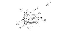
図9は従来の回転体の角度検出方法を適用した光学式のロータリーエンコーダの概念図である。
【0005】
同図に示すロータリーエンコーダ1は、回転体2と同軸の円盤3の外縁部に一つのスリット4を形成し、円盤3のスリット4を挟むように発光素子5及び受光素子6を配置し円盤3の回転角度に応じて円盤3のスリット4を透過する光(光パルス)を計数することにより回転体2の回転角度を検出するものである。なお、7はある回転角における回転体2の回転速度を検出するためのパルススケール、8は発光素子、9は受光素子、10は測距センサである(インクリメンタルタイプ)。
【0006】
インクリメンタルタイプのロータリーエンコーダは、スリット7のパターンI字形状と単純なため、構造が簡単になり、低コスト化が図れ、瞬間回転速度を検出するには優れている反面、検出途中でミスカウントされた場合にそのミスカウントが累積されて回転角度を正確に検出できない場合がある。このため、回転体2の回転角度を正確に検出する必要があるときは、検出途中のミスカウントが累積されることがなく、また、回転体2の高速回転に対して光電素子や電気回路の応答性を問題にする必要のないアブソリュートタイプのロータリーエンコーダが広く使用されている。
【0007】
一方、磁気式のロータリーエンコーダでは、回転体の回転軸と連動するアルミニウム等の常磁性体からなる円盤上に磁気記録可能な磁性膜を塗布、めっき若しくはスパッタ等で形成し、その磁性膜にビットパターンを記録し、ホール素子や磁気抵抗効果素子で回転体の回転角度を検出していた。
【0008】
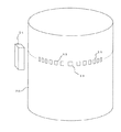
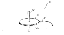
図10は他の従来の回転体の角度検出方法を適用した磁気式のロータリーエンコーダの概念図である。
【0009】
同図に示すロータリーエンコーダ11は、回転体12と同軸の円盤13の周面に予め複数のビットパターン14を記録しておき、円盤13の周面の近傍に磁気インピーダンス効果素子(MIセンサ等)15を配置して漏れ磁束を検出することで回転体12の回転角度を検出するものである。
【0010】
【特許文献1】
特開平7−42134号公報
【特許文献2】
特開平9−318388号公報
【0011】
【発明が解決しようとする課題】
しかしながら、アブソリュートタイプのロータリーエンコーダは、例えば回転体の1回転を360度という比較的粗い精度で検出する場合でも9ビット分のバイナリーコードが必要となるので、発光素子及び受光素子もそのビット数に応じて9組設けなければならない。
【0012】
従って、精度を向上させるほど発光素子及び受光素子の数が多くなり、その分構造が複雑になってコストが増加するだけでなく、消費電力も増加するので、電源停止時に用いるバックアップ用バッテリーとして大型電池を用いなければならないという問題があった。
【0013】
また、一般に、光学式のロータリーエンコーダは、発光ダイオードやレーザダイオードで発光した光を変調させ、反射光や透過光をフォトダイオードやフォトトランジスタで受光する構成となっているので、高価であり、機械的な衝撃に非常に弱いという問題点があった。このため、高分解能、軽量、高耐衝撃、かつ安価なロータリーエンコーダを得ることができなかった。
【0014】
さらに、光学式のロータリーエンコーダは、受光素子面を常に清浄な状態に維持する必要があり、劣悪な環境では使用が困難な場合がある。
【0015】
また、磁気式のロータリーエンコーダは、円盤とMIセンサ等のヘッドセンサーとで構成されているため、高耐衝撃性を有することを特徴としているが、分解能を向上させたい場合はビットパターンの高密度記録のため、磁性膜表面における漏れ磁束が減少してしまい、MIセンサとして使用しているホール素子や磁気抵抗効果素子の磁気感度が限界にきているため、これ以上の高分解能は不可能であるとされていた。
【0016】
そこで、本発明の目的は、上記課題を解決し、簡単な構成で信頼性の高い回転体の角度を検出することができる回転体の角度検出方法を提供することにある。
【0017】
【課題を解決するための手段】
上記目的を達成するために請求項1の発明は、回転体の周面にその周方向に沿って複数のアンテナ付きICを一定の間隔を隔てて設け、各アンテナ付きICのデータを無線式の読み取り装置で読み取ることにより回転体の回転角度を検出する回転体の角度検出方法である。
【0018】
請求項2の発明は、回転体に同軸となるように円盤を設け、円盤の外縁部又は周面にその周方向に沿って複数のアンテナ付きICを一定の間隔を隔てて設け、各アンテナ付きICのデータを無線式の読み取り装置で読み取ることにより回転体の回転角度を検出するものである。
【0019】
請求項3の発明は、請求項1または2に記載の構成に加え、読み取り装置からアンテナ付きICに電磁誘導で電力を供給すると共に、全アンテナ付きICに予め異なる番号のデータを個別に記憶させておき、読み取り装置から回転体若しくは回転体と同軸の円盤上の回転角度の基準となる位置を通過するアンテナ付きICからの番号のデータを読み取り、読み取り装置で番号のデータを回転体の角度のデータに換算することで回転体の回転角度を検出してもよい。
【0020】
請求項4の発明は、請求項1から3のいずれかに記載の構成に加え、読み取り装置からアンテナ付きICに電磁誘導で電力を供給すると共に、全アンテナ付きICに予め異なる番号のデータと回転体の角度との関係を示すデータとを予め個別に記憶させておき、読み取り装置から回転体若しくは回転体と同軸の円盤上の回転角度の基準となる位置を通過するアンテナ付きICからのデータを読み取ることで回転体の回転角度を検出してもよい。
【0021】
請求項5の発明は、請求項1から4のいずれかに記載の構成に加え、読み取り装置のアンテナを読み取り装置からケーブルで分離し、読み取り装置のアンテナを回転体若しくは回転体と同軸の円盤の回転角度の基準となる位置の近傍に円盤及び回転体と接触しないように支持部材で支持するようにしてもよい。
【0022】
請求項6の発明は、請求項1から5のいずれかに記載の構成に加え、アンテナ付きICのアンテナ及び読み取り装置のアンテナとしてループアンテナ、ダイポールアンテナまたはスリットアンテナを用いると共に、アンテナ付きIC内にデータを記憶するために不揮発性メモリを用いるのが好ましい。
【0023】
本発明によれば、回転体若しくは回転体と同軸になるように円盤を設け、回転体若しくは円盤のその周方向に複数のアンテナ付きICを一定の間隔を隔てて設け、各アンテナ付きICのデータを無線式の読み取り装置で読み取ることにより回転体の回転角度を検出するので、各アンテナ付きICに異なる番号をそれぞれ記憶させる場合、アンテナ付きICの幾何学的寸法に相関性がなく、回転角度精度を向上させるための角度の表示に多くのビット数が必要な場合でも、アンテナ付きICの寸法が大きくなることがない。
【0024】
従って、回転角度の検出精度を高くするためビット数を増加させて読み取り装置の数を増加する必要がなく、簡単な構成で、しかも低コストで回転体の回転角度の検出を実現することができる。また、アンテナ付きICに無線式の読み取り装置から電磁誘導により電力を非接触で供給するので、回転体側に電源を設ける必要がない。アンテナ付きICに不揮発性メモリを用いて、この不揮発性メモリにデータを記憶させることにより、回転体側にバックアップ用のバッテリーを用いる必要がなく、構成が簡素化できる。
【0025】
読み取り装置のアンテナを読み取り装置からケーブルで分離することにより、読み取り装置を上向きでも横向きでも傾斜させてもよくなり、配置の自由度が向上するので、操作者が回転角度表示を読み取りやすくなる。
【0026】
【発明の実施の形態】
以下、本発明の実施の形態を添付図面に基づいて詳述する。
【0027】
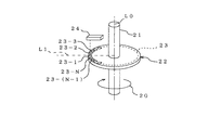
図1は本発明の回転体の角度検出方法の一実施の形態を示す概念図である。
【0028】
矢印20方向に回転する回転体21に同軸になるように円盤22が設けられている。円盤22の外縁部にはその周方向に沿って複数(N個とする。)のアンテナ付きIC23(23−1、23−2、23−3、…、23−(N−1)、23−N)が一定の間隔を隔てて配置されている。円盤22の外縁部の近傍(図では円盤21の上側)には円盤22の回転角度の基準となる位置(例えば、回転体21の中心軸L0と直交する仮想の線L1上の位置)を通過するアンテナ付きIC23のデータを読み取ることで回転体21の回転角度を検出する無線式の読み取り装置24が回転体21及び円盤22に接触しないように支持部材(図示せず。)で支持されている。
【0029】
図2(a)は図1に示したアンテナ付きICの一実施の形態を示す平面透視図であり、図2(b)は図2(a)の側面透視図であり、図2(c)は図1に示したアンテナ付きICのブロック図である。
【0030】
アンテナ付きIC23は、図2(a)、(b)に示すように絶縁体(例えばガラスエポキシ樹脂、セラミック、ガラス等)からなる基板25と、基板25上に設けられ、後述する分配器26、エネルギー変換部27、エネルギー蓄積部28、送受信部29、信号/データ処理部30等を有するICモジュール31と、ICモジュール31の送受信部29に接続され読み取り装置24(図1参照)との間で電波を送受信すると共に、読み取り装置24から電力を受けるためのアンテナ32と、ICモジュール31及びアンテナ32を基板25上に覆うモールド樹脂33とで構成されている。
【0031】
図2(c)に示す送受信部29のうちの送信部は、主にアンテナドライバ34及び変調回路35を有し、受信部は主に高周波増幅回路36及び復調回路37を有している。
【0032】
分配器26は受信した電波を送受信部29側とエネルギー変換部27側との二つに分配する回路である。
【0033】
エネルギー変換部27は、読み取り装置24からの電波が受信されて電磁誘導によって発生した電力を所定の電圧の交流電流(高周波電流)に変圧し、整流(例えば全波整流)し、平滑化し、安定化して直流電流に変換する回路である。
【0034】
エネルギー充電部28は読み取り装置24(図1参照)からの電波を受信している間にエネルギーの一部を充電しておき、アンテナ付きIC23の送信時に使用するためのでものであり、例えば電気二重層コンデンサ等の小型で大容量のコンデンサが用いられる。
【0035】
変調回路35は、発振回路で発振し、逓倍回路(共に図示せず。)で逓倍された搬送波を、信号/データ処理部30からの信号で変調する回路であり、アンテナドライバ34は送受信の切換えを行う回路である。なお、この変調回路35を省略した回路構成も可能である。
【0036】
高周波増幅回路36は受信した電波を増幅する回路であり、復調回路37は受信した電波から電気信号を取り出す回路である。高周波増幅回路36も省略可能である。
【0037】
信号/データ処理部30は、演算・制御を行うCPU38、データの記憶を行うメモリ(RAM39a、ROM39b、39c)39及び入力・出力を行うI/Oポート40を有しており、それぞれアドレスバス41、データバス42、コントロールバス43で接続され、I/Oポート40はインターフェイス44に接続されている。
【0038】
メモリ39にはアンテナ付きIC23の動作プログラムが記憶されたROM39aと、RAM39bと、読み取り装置24からのデータを記憶する不揮発性メモリ39cとが用いられている。不揮発性メモリ39cはアンテナ付きIC23を識別するための異なる番号のデータとアンテナ付きIC23が固定される回転体21の円盤22の回転角度との関係を示すデータとが記憶されるようになっている。
【0039】
不揮発性メモリ39cにはEPROM(UV−Erasable Programmable Read Only Memory)、EEPROM(Electrically Erasable Programmable ROM)、フラッシュメモリのいずれを用いてもよい。
【0040】
アンテナ32には指向性を有するアンテナを用いるのが好ましく、具体的にはループアンテナが好ましい(もし無指向性アンテナを用いると、例えばアンテナ付きIC23−1に隣接するアンテナ付きIC23−2、23−Nからの電波を読み取り装置24が誤受信してしまうおそれがあるからである。)。ループアンテナは図では方形ループアンテナが示されているが、円形ループアンテナを用いてもよい。また、ループの巻き数は図では1巻きであるが利得を増やすため複数回であるのが好ましい。
【0041】
アンテナ付きIC23は円盤22(図1参照)の一方(図1では上側)の外縁部に形成された凹部(図示せず。)内にループアンテナ32のボアサイトが読取装置のアンテナのボアサイトにほぼ一致するように接着剤で固定されている。
【0042】
図3は図1に示した読み取り装置のブロック図である。
【0043】
読み取り装置24は、アンテナ付きIC23(図1参照)との間で電波を送受信すると共に、アンテナ付きIC23に電力を供給するためのアンテナ45と、送受信部46と、信号/データ処理部47と、表示部48と、電源(電池若しくは直流安定化電源)49と、キーボード接続用端子50とを有している。なお、49aはスイッチである。
【0044】
読み取り装置24の絶縁体からなる筐体の一方の面(図1では上側の面)には表示部48やスイッチ49aが配置され、筐体内の他方の面(図1では下側の面)側にはアンテナ45が内蔵されている。筐体の底部(図1では左側)にはキーボード接続用端子50が設けられている(いずれも図示せず。)。
【0045】
送受信部46は、アンテナドライバ51、高周波増幅器52、復調器53及び変調器54を有し、信号/データ処理部47は、CPU55、I/Oポート56、メモリ(RAM56a、ROM56b)56を有しており、それぞれアドレスバス57、データバス58、コントロールバス59で接続され、I/Oポート56はインターフェイス60に接続されている。
【0046】
筐体内に内蔵されたアンテナ45としては、円盤22(図1参照)の回転角度の基準となる位置を通過するアンテナ付きIC(読み取り装置24のアンテナ45に最も近いアンテナ付きIC)23−1(図1参照)とだけ電波の送受信を行う必要があるため、指向性アンテナ、例えばループアンテナを用いるのが好ましい(もし、無指向性アンテナを用いると、複数のアンテナ付きIC23に同一の番号のデータ等が記憶されてしまうからである)。
【0047】
表示部48は回転体21(円盤22)の角度を表示するものであり、例えば液晶表示盤が用いられる(LEDディスプレイや表示用LEDを用いてもよい。)。
【0048】
次に図1に示した回転体角度検出装置の動作について説明する。
【0049】
(準備段階)
全アンテナ付きIC23の不揮発性メモリ39cには何もデータが記憶されていないものとする。
【0050】
図示しない操作者は、読み取り装置24のキーボード接続用端子50にキーボード61を接続し(共に図3参照)、読み取り装置24に内蔵されたアンテナ45(図3参照)が円盤22の回転角度の基準となる位置の上側に位置するように図示しない支持部材で支持した後、円盤22上のアンテナ付きIC23(この場合23−1とする。)が読み取り装置24のアンテナの真下に位置するように回転させ、読み取り装置24のスイッチ49a(図3参照)をオンにする。
【0051】
操作者がスイッチ49aをオンにすると、読み取り装置24から一定時間電波がアンテナ付きIC23−1に送信される(送信時には表示部48(図3参照)に送信モードである旨が表示され、待機時には表示部48に受信モードである旨が表示されるようになっている。)。
【0052】
この読み取り装置24からの電波により、アンテナ付きIC23−1に電磁誘導により電力が非接触で供給される。アンテナ付きIC23−1は、この電力によりICモジュール31(図2(a)、(b)参照)を立ち上げると共に、エネルギー充電部28(図2(c)参照)に充電させた後、不揮発性メモリ39cに記憶されたデータ(この時点では何もデータが記憶されていない。)を読み出し、その読み出したデータを変調回路35で変調し、アンテナ32(共に図2(c)参照)から読み取り装置24に送信した後、受信モードに切換えて待機する。
【0053】
読み取り装置24は、アンテナ付きIC23−1からの電波を受信し、不揮発性メモリ39cにデータがまだ何も記憶されていない旨を表示部48に表示する。
【0054】
操作者は、アンテナ付きIC23−1に何もデータが記憶されていないことを確認した後、読み取り装置24に接続されたキーボード61を操作し、アンテナ付きIC23−1の番号(ID:例えば23−1)と、番号(23−1)と回転体21の角度との関係を示すデータ(例えば23−1=0)とを入力する。
【0055】
読み取り装置24は、両データが入力されると、両データの信号を変調器54で変調し、その変調された電波をアンテナ付きIC23−1に送信する(このとき表示部48には送信モードである旨が表示されるようになっている。)。読み取り装置24は、データの電波送信後は受信モードにして待機する(このとき表示部48には受信モードである旨が表示されるようになっている。)。
【0056】
アンテナ付きIC23−1は、読み取り装置24から送信された番号(23−1)のデータと、回転体21の角度のデータとを不揮発性メモリ39cに書き込む(記憶する)。アンテナ付きIC23−1はエネルギー充電部28に充電された電力を用いて不揮発性メモリ39cに書き込まれた両データを読み出し、読み取り装置24にそのデータの信号で変調された電波を送信した後、受信モードで待機する(操作者がデータ入力の確認を行うためである。)。
【0057】
読み取り装置24は、アンテナ付きIC23−1からの電波を受信すると、アンテナ付きIC23−1の番号(23−1)のデータと角度のデータとを表示部48に一定時間表示する。これ以後、読み取り装置24からアンテナ付きIC23−1に電波が送信されるまではアンテナ付きIC23−1には電力の供給が停止されることになるが、アンテナ付きIC23−1の番号のデータ及び角度のデータは、不揮発性メモリ39cに記憶されるため、両データが消失することがなく、しかもバックアップの必要もない。
【0058】
以下、操作者は、回転体21を回転させて順次アンテナ付きIC23−2、23−3、…、23−Nに番号(23−2、23−3、…、23−N)及び角度のデータで変調された電波を読み取り装置24から送信してアンテナ付きIC23−2、23−3、…、23−Nの不揮発性メモリ39cにそれぞれ記憶させる。
【0059】
なお、操作者がアンテナ付きIC23の番号若しくは角度のデータを入力ミスした場合には、読み取り装置24から不揮発性メモリ39cのデータを消去する信号で変調された電波を送信し、再度番号若しくは角度のデータの電波を送信することで訂正することができるようになっている。
【0060】
全アンテナ付きIC23に番号のデータと角度のデータとを記憶させると準備段階が終了する。準備段階終了後は、操作者はスイッチ49aをオフにし、キーボード接続用端子50からキーボード61を取り外す。
【0061】
(回転体角度検出段階)
操作者が読み取り装置24のスイッチ49aをオンにすると、読み取り装置24が作動し、読み取り装置24のアンテナ45からアンテナ付きIC23に電波が一定時間送信される。読み取り装置24のアンテナ45のボアサイトの位置に回転してきたアンテナ付きIC23だけ電波を受信し、アンテナ付きIC23のICモジュール31が立ち上がると共にエネルギー蓄積部28が充電され、エネルギー蓄積部28の充電後、アンテナ付きIC23は送信モードに切り換わり不揮発性メモリ39cに記憶された番号のデータと角度のデータとを読み出して、変調回路35で変調し、アンテナ32から読み取り装置24に送信した後、受信モードに切り換わり待機する。
【0062】
読み取り装置24はアンテナ付きIC23からの電波を受信すると、番号のデータと角度のデータとを表示部48に一定時間表示する。
【0063】
このように、回転体21の回転中に読み取り装置24のスイッチ49aをオンにすることにより、読み取り装置24のアンテナの真下に位置するアンテナ付きIC23は読み取り装置24からの電波をエネルギーとして番号のデータと角度のデータとを読み取り装置24に送信し、読み取り装置24はアンテナ付きIC23の番号と角度とを表示部48に表示するので、回転体21の角度を容易かつ正確に検出することができる。
【0064】
以上において、本実施の形態によれば、簡単な構成で信頼性の高い回転体の角度を検出することができる回転体の角度検出方法を提供することができる。
【0065】
なお、本実施の形態では表示部48にアンテナ付きIC23の番号のデータと角度のデータとを表示する場合で説明したが、本発明はこれに限定されるものではなく、アンテナ付きIC23に番号のデータのみ記憶させておき、読み取り装置24で番号のデータを信号/データ処理部47で回転体21の角度に換算して得られた角度の値を表示部48に表示するようにしてもよい。
【0066】
図4(a)は本発明の回転体の角度検出方法の他の実施の形態を示す概念図であり、図4(b)は図4(a)に示した読み取り装置に用いられるアンテナ部の拡大平面透視図であり、図4(c)は図4(b)の側面透視図である。以下、図1〜図3に示した部材と同様の部材には共通の符号を用いた。
【0067】
図4(a)〜(c)に示した回転体角度検出方法の図1に示した回転体角度検出方法との相違点は、読み取り装置からアンテナをケーブルで分離して検出する点である。
【0068】
読み取り装置62は、読み取り装置本体63と、ケーブル64と、アンテナ部65とで構成されている。
【0069】
アンテナ部65は、絶縁体(例えばガラスエポキシ樹脂、セラミック、ガラス等)からなる基板66と、基板66上に配置された導体線(錫めっき銅線、金めっき銅線、銀めっき銅線等)からなるループアンテナ45と、基板66上にループアンテナ45を覆うモールド樹脂67とを有している。ループアンテナ45は図では導体線45を基板66上に配置した場合を示しているが、片面プリント基板を用いて構成してもよい。また、ループの巻き数は図では1巻きであるが限定されるものではなく、ループの形状も四角形に限定されず円形でもよい。
【0070】
読み取り装置本体63とアンテナ部65との間を接続するケーブル64には同軸ケーブルを用いるのが好ましい。
【0071】
このように読み取り装置62を構成しても図1に示した回転体の角度検出方法と同様の効果が得られるだけでなく、読み取り装置本体63の配置の自由度が向上するので、表示部が見やすくなる。
【0072】
図5は本発明の回転体の角度検出方法の他の実施の形態を示す概念図である。
【0073】
図5に示した回転体の角度検出方法の図1に示した回転体の角度検出方法との相違点は、アンテナ付きIC23を円盤22の周面に設けた点である。
【0074】
このようにアンテナ付きIC23を円盤22に設けると共に読み取り装置24を配置しても図1に示した回転体の角度検出方法と同様の効果が得られる。
【0075】
図6は本発明の回転体の角度検出方法の他の実施の形態を示す概念図である。
【0076】
図6に示した回転体の角度検出方法の図4(a)〜(c)に示した回転体の角度検出方法との相違点は、アンテナ付きIC23を円盤22の周面に設けた点である。
【0077】
このようにアンテナ付きIC23を円盤の周面に配置しても図4(a)〜(c)に示した回転体の角度検出方法と同様の効果が得られる。
【0078】
図7は本発明の回転体の角度検出方法の他の実施の形態を示す概念図である。
【0079】
図7に示した回転体の角度検出方法の図5に示した回転体の角度検出方法との相違点は、複数のアンテナ付きIC23を回転体の周面にその周方向に沿って一定の間隔を隔てて設けた点である。
【0080】
このようにアンテナ付きIC23を回転体70の周面に配置しても図5に示した回転体の角度検出方法と同様の効果が得られる。
【0081】
図8は本発明の回転体の角度検出方法の他の実施の形態を示す概念図である。
【0082】
図8に示した回転体の角度検出方法の図6に示した回転体の角度検出方法との相違点は、複数のアンテナ付きIC23を回転体70の周面にその周方向に沿って一定の間隔を隔てて設けた点である。
【0083】
このようにアンテナ付きIC23を回転体70の周面に配置しても図5に示した回転体の角度検出方法と同様の効果が得られる。
【0084】
【発明の効果】
以上要するに本発明によれば、簡単な構成で信頼性の高い回転体の角度を検出することができる回転体の角度検出方法の提供を実現することができる。
【図面の簡単な説明】
【図1】本発明の回転体の角度検出方法の一実施の形態を示す概念図である。
【図2】(a)は図1に示したアンテナ付きICの一実施の形態を示す平面透視図であり、(b)は(a)の側面透視図であり、(c)は図1に示したアンテナ付きICのブロック図である。
【図3】図1に示した読み取り装置のブロック図である。
【図4】(a)は本発明の回転体の角度検出方法の他の実施の形態を示す概念図であり、(b)は(a)に示した読み取り装置に用いられるアンテナ部の拡大平面透視図であり、(c)は(b)の側面透視図である。
【図5】本発明の回転体の角度検出方法の他の実施の形態を示す概念図である。
【図6】本発明の回転体の角度検出方法の他の実施の形態を示す概念図である。
【図7】本発明の回転体の角度検出方法の他の実施の形態を示す概念図である。
【図8】本発明の回転体の角度検出方法の他の実施の形態を示す概念図である。
【図9】従来の回転体の角度検出方法を適用した光学式のロータリーエンコーダの概念図である。
【図10】他の従来の回転体の角度検出方法を適用した磁気式のロータリーエンコーダの概念図である。
【符号の説明】
21 回転体
22 円盤
23(23−1〜23−N) アンテナ付きIC
24 読み取り装置[0001]
TECHNICAL FIELD OF THE INVENTION
The present invention relates to a method for detecting an angle of a rotating body.
[0002]
[Prior art]
As means for detecting the rotation angle of the rotating body, an optical rotary encoder shown in FIG. 9 (for example, see Patent Document 1) and a magnetic rotary encoder shown in FIG. 10 (for example, see Patent Document 2) have been known. I have.
[0003]
In the optical rotary encoder, for example, a disk having slits formed at a predetermined pitch in the circumferential direction is provided so as to be coaxial with the rotating body, and a light pulse generated according to the rotation angle of the disk is counted and the rotation angle is calculated. And an absolute type that detects the rotation angle by reading the binary code using a rotating disk in which a binary code corresponding to the rotation angle is encoded by a plurality of slit rows using a rotating disk.
[0004]
FIG. 9 is a conceptual diagram of an optical rotary encoder to which a conventional method for detecting the angle of a rotating body is applied.
[0005]
The rotary encoder 1 shown in FIG. 1 has one slit 4 formed at the outer edge of a disk 3 coaxial with the rotating body 2, and a light emitting element 5 and a light receiving element 6 are arranged so as to sandwich the slit 4 of the disk 3. The rotation angle of the rotating body 2 is detected by counting the light (light pulse) transmitted through the slit 4 of the disk 3 according to the rotation angle of the rotating body 2. 7 is a pulse scale for detecting the rotation speed of the rotating body 2 at a certain rotation angle, 8 is a light emitting element, 9 is a light receiving element, and 10 is a distance measuring sensor (incremental type).
[0006]
Since the incremental type rotary encoder has a simple pattern I-shape of the slit 7, the structure is simple, the cost can be reduced, and it is excellent for detecting the instantaneous rotation speed. In such a case, the miscount may be accumulated and the rotation angle may not be accurately detected. For this reason, when it is necessary to accurately detect the rotation angle of the rotating body 2, miscounts during detection are not accumulated, and the photoelectric element and the electric circuit of the photoelectric element and the electric circuit are prevented from rotating at high speed. Absolute-type rotary encoders that do not require responsiveness are widely used.
[0007]
On the other hand, in the case of a magnetic rotary encoder, a magnetic film that can be magnetically recorded is formed by coating, plating, or sputtering on a disk made of a paramagnetic material such as aluminum that is interlocked with the rotating shaft of the rotating body, and a bit is formed on the magnetic film. The pattern was recorded, and the rotation angle of the rotating body was detected by a Hall element or a magnetoresistive element.
[0008]
FIG. 10 is a conceptual diagram of a magnetic rotary encoder to which another conventional method for detecting the angle of a rotating body is applied.
[0009]
In the rotary encoder 11 shown in FIG. 1, a plurality of bit patterns 14 are recorded in advance on the peripheral surface of a disk 13 coaxial with the rotating body 12, and a magneto-impedance effect element (such as an MI sensor) is provided near the peripheral surface of the disk 13. The rotation angle of the rotating body 12 is detected by arranging the reference numeral 15 and detecting the leakage magnetic flux.
[0010]
[Patent Document 1]
JP-A-7-42134
[Patent Document 2]
JP-A-9-318388
[0011]
[Problems to be solved by the invention]
However, the absolute-type rotary encoder requires a binary code of 9 bits even when detecting one rotation of the rotating body with a relatively coarse accuracy of 360 degrees, for example. Nine sets must be provided accordingly.
[0012]
Therefore, as the accuracy is improved, the number of light-emitting elements and light-receiving elements is increased, and the structure becomes more complicated, which increases the cost and also increases the power consumption. There was a problem that a battery had to be used.
[0013]
In general, an optical rotary encoder is configured to modulate light emitted by a light emitting diode or a laser diode and to receive reflected light or transmitted light by a photodiode or a phototransistor. There was a problem that it was very vulnerable to mechanical shock. For this reason, a high-resolution, lightweight, high-impact, and inexpensive rotary encoder could not be obtained.
[0014]
Further, the optical rotary encoder needs to always maintain the light receiving element surface in a clean state, and it may be difficult to use the optical rotary encoder in a poor environment.
[0015]
A magnetic rotary encoder is characterized by having high shock resistance because it is composed of a disk and a head sensor such as an MI sensor. Because of the recording, the leakage magnetic flux on the surface of the magnetic film is reduced, and the magnetic sensitivity of the Hall element or the magnetoresistive element used as the MI sensor has reached its limit. It was supposed to be.
[0016]
Therefore, an object of the present invention is to solve the above-mentioned problem and to provide a rotating body angle detection method capable of detecting a highly reliable rotating body angle with a simple configuration.
[0017]
[Means for Solving the Problems]
In order to achieve the above object, the invention according to claim 1 provides a plurality of ICs with antennas on a peripheral surface of a rotating body along a circumferential direction at a fixed interval, and wirelessly transmits data of each IC with antennas. This is a method for detecting the angle of rotation of a rotating body by detecting the rotation angle of the rotating body by reading with a reading device.
[0018]
According to the second aspect of the present invention, a disk is provided so as to be coaxial with the rotating body, and a plurality of ICs with antennas are provided at regular intervals on the outer edge or peripheral surface of the disk along the circumferential direction thereof. The rotation angle of the rotating body is detected by reading the data of the IC with a wireless reading device.
[0019]
According to a third aspect of the present invention, in addition to the configuration according to the first or second aspect, power is supplied from the reader to the IC with the antenna by electromagnetic induction, and data having different numbers are individually stored in advance in all the ICs with the antenna. In advance, the reader reads number data from the IC with an antenna passing through a reference position of a rotation angle on a rotating body or a disk coaxial with the rotating body, and reads the number data with the reading apparatus to determine the angle of the rotating body. The rotation angle of the rotating body may be detected by converting the data into data.
[0020]
According to a fourth aspect of the present invention, in addition to the configuration according to any one of the first to third aspects, power is supplied from the reader to the IC with the antenna by electromagnetic induction, and data and rotation of different numbers are previously supplied to all the ICs with the antenna. Data indicating the relationship with the body angle is separately stored in advance, and the data from the IC with the antenna passing from the reading device to the reference position of the rotation angle on the rotating body or the disk coaxial with the rotating body is stored. The rotation angle of the rotating body may be detected by reading.
[0021]
According to a fifth aspect of the present invention, in addition to the configuration according to any one of the first to fourth aspects, the antenna of the reading device is separated from the reading device by a cable, and the antenna of the reading device is formed of a rotating body or a disk coaxial with the rotating body. The disk may be supported by a support member so as not to come into contact with the disk and the rotating body in the vicinity of the reference position of the rotation angle.
[0022]
According to a sixth aspect of the present invention, in addition to the configuration according to any one of the first to fifth aspects, a loop antenna, a dipole antenna, or a slit antenna is used as an antenna of the IC with an antenna and an antenna of the reader, and the IC with the antenna is provided inside the IC with the antenna. Preferably, a non-volatile memory is used to store data.
[0023]
According to the present invention, a rotating body or a disk is provided so as to be coaxial with the rotating body, a plurality of ICs with antennas are provided at regular intervals in a circumferential direction of the rotating body or the disk, and data of each IC with antennas is provided. Since the rotation angle of the rotating body is detected by reading the data with a wireless reading device, when different numbers are stored in the respective ICs with antennas, there is no correlation between the geometric dimensions of the ICs with antennas and the rotation angle accuracy Even when a large number of bits are required to display the angle for improving the size, the size of the antenna-equipped IC does not increase.
[0024]
Therefore, it is not necessary to increase the number of bits and increase the number of reading devices in order to increase the detection accuracy of the rotation angle, and the rotation angle of the rotating body can be detected with a simple configuration at low cost. . In addition, since electric power is supplied to the IC with the antenna from the wireless reading device by electromagnetic induction in a non-contact manner, there is no need to provide a power source on the rotating body side. By using a nonvolatile memory for the IC with an antenna and storing data in the nonvolatile memory, it is not necessary to use a backup battery on the rotating body side, and the configuration can be simplified.
[0025]
By separating the antenna of the reading device from the reading device with a cable, the reading device may be tilted upward, sideways, or inclined, and the degree of freedom of arrangement is improved, so that the operator can easily read the rotation angle display.
[0026]
BEST MODE FOR CARRYING OUT THE INVENTION
Hereinafter, embodiments of the present invention will be described in detail with reference to the accompanying drawings.
[0027]
FIG. 1 is a conceptual diagram showing one embodiment of a method for detecting the angle of a rotating body of the present invention.
[0028]
A disk 22 is provided coaxially with a rotating body 21 rotating in the direction of arrow 20. A plurality (N) of ICs 23 with antennas (23-1, 23-2, 23-3,..., 23- (N-1), 23- N) are arranged at regular intervals. In the vicinity of the outer edge of the disk 22 (the upper side of the disk 21 in the figure), a position serving as a reference of the rotation angle of the disk 22 (for example, a position on a virtual line L1 orthogonal to the center axis L0 of the rotating body 21) is passed. A wireless reader 24 that detects the rotation angle of the rotating body 21 by reading data from the IC 23 with an antenna is supported by a support member (not shown) so as not to contact the rotating body 21 and the disk 22. .
[0029]
2A is a perspective plan view showing an embodiment of the IC with an antenna shown in FIG. 1, FIG. 2B is a side perspective view of FIG. 2A, and FIG. FIG. 2 is a block diagram of the IC with an antenna shown in FIG. 1.
[0030]
As shown in FIGS. 2A and 2B, the IC with an antenna 23 is provided with a substrate 25 made of an insulator (for example, glass epoxy resin, ceramic, glass, or the like), and a distributor 26 which is provided on the substrate 25 and which will be described later. An IC module 31 having an energy conversion unit 27, an energy storage unit 28, a transmission / reception unit 29, a signal / data processing unit 30, etc., and a reading device 24 (see FIG. 1) connected to the transmission / reception unit 29 of the IC module 31 It comprises an antenna 32 for transmitting and receiving radio waves and receiving power from the reader 24, and a mold resin 33 for covering the IC module 31 and the antenna 32 on the substrate 25.
[0031]
The transmission section of the transmission / reception section 29 shown in FIG. 2C mainly has an antenna driver 34 and a modulation circuit 35, and the reception section mainly has a high-frequency amplification circuit 36 and a demodulation circuit 37.
[0032]
The distributor 26 is a circuit that distributes the received radio wave to two parts, that is, the transmission / reception unit 29 side and the energy conversion unit 27 side.
[0033]
The energy conversion unit 27 receives the radio wave from the reading device 24, transforms the power generated by the electromagnetic induction into an alternating current (high-frequency current) having a predetermined voltage, rectifies (for example, full-wave rectification), smoothes, and stabilizes the power. And converts it into a DC current.
[0034]
The energy charging unit 28 charges a part of the energy while receiving the radio wave from the reading device 24 (see FIG. 1), and uses the energy when transmitting the IC 23 with an antenna. A small and large-capacity capacitor such as a multilayer capacitor is used.
[0035]
The modulation circuit 35 oscillates with an oscillation circuit and modulates the carrier wave multiplied by a multiplication circuit (both not shown) with a signal from the signal / data processing unit 30. The antenna driver 34 switches between transmission and reception. Is a circuit that performs the following. Note that a circuit configuration in which the modulation circuit 35 is omitted is also possible.
[0036]
The high-frequency amplification circuit 36 is a circuit that amplifies the received radio wave, and the demodulation circuit 37 is a circuit that extracts an electric signal from the received radio wave. The high-frequency amplifier circuit 36 can also be omitted.
[0037]
The signal / data processing unit 30 has a CPU 38 for performing arithmetic and control, memories (RAM 39a, ROM 39b, 39c) 39 for storing data, and an I / O port 40 for performing input and output. , A data bus 42 and a control bus 43, and the I / O port 40 is connected to an interface 44.
[0038]
The memory 39 includes a ROM 39 a storing an operation program of the IC with an antenna 23, a RAM 39 b, and a non-volatile memory 39 c for storing data from the reader 24. The non-volatile memory 39c stores data of a different number for identifying the IC 23 with an antenna and data indicating the relationship between the rotation angle of the disk 22 of the rotating body 21 to which the IC 23 with the antenna is fixed. .
[0039]
As the nonvolatile memory 39c, any of an EPROM (UV-Erasable Programmable Read Only Memory), an EEPROM (Electrically Erasable Programmable ROM), and a flash memory may be used.
[0040]
It is preferable to use an antenna having directivity as the antenna 32. Specifically, a loop antenna is preferable (if an omnidirectional antenna is used, for example, the ICs 23-2, 23-23 adjacent to the IC 23-1 adjacent to the antenna are used. This is because the reading device 24 may receive the radio wave from N erroneously.) Although a square loop antenna is shown in the figure as the loop antenna, a circular loop antenna may be used. Although the number of turns of the loop is one in the figure, it is preferable that the number of turns is plural in order to increase the gain.
[0041]
The antenna-equipped IC 23 has the bore sight of the loop antenna 32 in the recess (not shown) formed in the outer edge of one side (the upper side in FIG. 1) of the disk 22 (see FIG. 1). It is fixed with an adhesive so that it almost matches.
[0042]
FIG. 3 is a block diagram of the reading device shown in FIG.
[0043]
The reading device 24 transmits and receives radio waves to and from the IC with antenna 23 (see FIG. 1), and supplies an antenna 45 for supplying power to the IC with antenna 23, a transmitting and receiving unit 46, a signal / data processing unit 47, It has a display section 48, a power supply (battery or stabilized DC power supply) 49, and a keyboard connection terminal 50. In addition, 49a is a switch.
[0044]
The display unit 48 and the switch 49a are arranged on one surface (the upper surface in FIG. 1) of the housing made of an insulator of the reading device 24, and the other surface (the lower surface in FIG. 1) inside the housing. Has a built-in antenna 45. A keyboard connection terminal 50 is provided on the bottom of the housing (the left side in FIG. 1) (both are not shown).
[0045]
The transmission / reception unit 46 has an antenna driver 51, a high-frequency amplifier 52, a demodulator 53, and a modulator 54, and the signal / data processing unit 47 has a CPU 55, an I / O port 56, and a memory (RAM 56a, ROM 56b) 56. The I / O port 56 is connected to an interface 60 by an address bus 57, a data bus 58, and a control bus 59, respectively.
[0046]
As the antenna 45 built in the housing, an IC with an antenna (an IC with an antenna closest to the antenna 45 of the reading device 24) 23-1 that passes through a position that is a reference of the rotation angle of the disk 22 (see FIG. 1) 23-1 ( It is preferable to use a directional antenna, for example, a loop antenna (if an omnidirectional antenna is used, the same number of data is stored in a plurality of ICs with antennas 23) because it is necessary to transmit and receive radio waves only with the IC 23 shown in FIG. Etc. are stored).
[0047]
The display unit 48 displays the angle of the rotating body 21 (the disk 22), and for example, uses a liquid crystal display panel (an LED display or a display LED may be used).
[0048]
Next, the operation of the rotating body angle detecting device shown in FIG. 1 will be described.
[0049]
(Preparation stage)
It is assumed that no data is stored in the nonvolatile memory 39c of the IC 23 with all antennas.
[0050]
An operator (not shown) connects a keyboard 61 to the keyboard connection terminal 50 of the reader 24 (both shown in FIG. 3), and an antenna 45 (see FIG. 3) built in the reader 24 is used as a reference for the rotation angle of the disk 22. After being supported by a support member (not shown) so as to be located above the position where the position becomes, the IC with an antenna 23 (in this case, 23-1) on the disk 22 is rotated so as to be located directly below the antenna of the reading device 24. Then, the switch 49a (see FIG. 3) of the reading device 24 is turned on.
[0051]
When the operator turns on the switch 49a, a radio wave is transmitted from the reading device 24 to the IC 23-1 with the antenna for a certain period of time (when transmitting, the display unit 48 (see FIG. 3) indicates that the transmission mode is set, and when in standby, The display unit 48 displays the reception mode.)
[0052]
Electric power is supplied to the IC with antenna 23-1 by electromagnetic induction in a non-contact manner by radio waves from the reading device 24. The IC with an antenna 23-1 starts up the IC module 31 (see FIGS. 2A and 2B) with this electric power, and charges the energy charging unit 28 (see FIG. 2C). The data stored in the memory 39c (no data is stored at this time) is read, the read data is modulated by the modulation circuit 35, and the data is read from the antenna 32 (both refer to FIG. 2C). After the transmission to 24, the mode is switched to the reception mode and the apparatus stands by.
[0053]
The reading device 24 receives the radio wave from the IC with antenna 23-1, and displays on the display unit 48 that no data is stored in the nonvolatile memory 39c yet.
[0054]
After confirming that no data is stored in the IC with an antenna 23-1, the operator operates the keyboard 61 connected to the reading device 24, and the number (ID: for example, 23- 1) and data (for example, 23-1 = 0) indicating the relationship between the number (23-1) and the angle of the rotating body 21 are input.
[0055]
When both data are input, the reading device 24 modulates the signals of both data by the modulator 54 and transmits the modulated radio waves to the IC with antenna 23-1 (at this time, the display unit 48 displays the transmission mode). Is displayed.) The reading device 24 sets the reception mode after the radio wave transmission of the data, and stands by (at this time, the display unit 48 indicates that the reception mode is set).
[0056]
The IC with antenna 23-1 writes (stores) the data of the number (23-1) transmitted from the reading device 24 and the data of the angle of the rotating body 21 in the nonvolatile memory 39c. The IC with an antenna 23-1 reads both data written in the non-volatile memory 39c using the power charged in the energy charging unit 28, transmits a radio wave modulated by the data signal to the reading device 24, and then receives the data. Standby in mode (because the operator confirms data entry).
[0057]
When receiving the radio wave from the IC with an antenna 23-1, the reading device 24 displays the data of the number (23-1) and the data of the angle of the IC with an antenna 23-1 on the display unit 48 for a certain period of time. Thereafter, the supply of power to the IC 23-1 with the antenna is stopped until the radio wave is transmitted from the reading device 24 to the IC 23-1 with the antenna. Is stored in the non-volatile memory 39c, so that both data are not lost, and there is no need for backup.
[0058]
Hereinafter, the operator rotates the rotating body 21 and sequentially assigns numbers (23-2, 23-3,..., 23-N) and angle data to the ICs 23-2, 23-3,. Are transmitted from the reader 24 and stored in the nonvolatile memories 39c of the ICs with antennas 23-2, 23-3,..., 23-N.
[0059]
If the operator makes a mistake in inputting the number or angle data of the IC with antenna 23, the reader 24 transmits a radio wave modulated by a signal for erasing the data in the nonvolatile memory 39c, and again transmits the number or angle. It can be corrected by transmitting data radio waves.
[0060]
The preparatory stage ends when the number data and the angle data are stored in the ICs 23 with all antennas. After the preparation stage, the operator turns off the switch 49a and removes the keyboard 61 from the keyboard connection terminal 50.
[0061]
(Rotating body angle detection stage)
When the operator turns on the switch 49a of the reading device 24, the reading device 24 operates, and a radio wave is transmitted from the antenna 45 of the reading device 24 to the IC 23 with an antenna for a certain period of time. Only the IC 23 with the antenna that has rotated to the position of the boresight of the antenna 45 of the reader 24 receives radio waves, the IC module 31 of the IC 23 with the antenna rises, the energy storage unit 28 is charged, and after the energy storage unit 28 is charged, The IC 23 with the antenna switches to the transmission mode, reads out the data of the number and the data of the angle stored in the non-volatile memory 39c, modulates it with the modulation circuit 35, transmits the data from the antenna 32 to the reader 24, and then switches to the reception mode Switch and wait.
[0062]
When receiving the radio wave from the IC 23 with the antenna, the reading device 24 displays the data of the number and the data of the angle on the display unit 48 for a certain time.
[0063]
As described above, by turning on the switch 49a of the reading device 24 while the rotating body 21 is rotating, the IC 23 with the antenna located immediately below the antenna of the reading device 24 uses the radio wave from the reading device 24 as energy to convert the number data. And the angle data are transmitted to the reading device 24, and the reading device 24 displays the number and angle of the IC 23 with the antenna on the display unit 48, so that the angle of the rotating body 21 can be easily and accurately detected.
[0064]
As described above, according to the present embodiment, it is possible to provide a rotating body angle detection method capable of detecting a highly reliable rotating body angle with a simple configuration.
[0065]
In the present embodiment, the case where the data of the number of the IC 23 with the antenna and the data of the angle are displayed on the display unit 48 has been described, but the present invention is not limited to this, and the number of the number of the IC 23 with the antenna is displayed. Only the data may be stored, and the value of the angle obtained by converting the number data by the reading device 24 into the angle of the rotating body 21 by the signal / data processing unit 47 may be displayed on the display unit 48.
[0066]
FIG. 4A is a conceptual diagram showing another embodiment of the method for detecting the angle of a rotating body according to the present invention, and FIG. 4B is a schematic diagram of an antenna unit used in the reader shown in FIG. FIG. 4C is an enlarged plan perspective view, and FIG. 4C is a side perspective view of FIG. Hereinafter, the same members as those shown in FIGS. 1 to 3 are denoted by the same reference numerals.
[0067]
4A to 4C is different from the rotating body angle detecting method shown in FIG. 1 in that the antenna is separated from the reader by a cable and detected.
[0068]
The reading device 62 includes a reading device main body 63, a cable 64, and an antenna unit 65.
[0069]
The antenna section 65 includes a substrate 66 made of an insulator (eg, glass epoxy resin, ceramic, glass, etc.) and a conductor wire (tin-plated copper wire, gold-plated copper wire, silver-plated copper wire, etc.) disposed on the substrate 66. , And a mold resin 67 that covers the loop antenna 45 on the substrate 66. Although the loop antenna 45 shows the case where the conductor wire 45 is arranged on the substrate 66 in the drawing, it may be configured using a single-sided printed circuit board. Although the number of turns of the loop is one in the figure, the number is not limited, and the shape of the loop is not limited to a square but may be a circle.
[0070]
It is preferable to use a coaxial cable as the cable 64 connecting between the reading device main body 63 and the antenna unit 65.
[0071]
Even if the reading device 62 is configured in this manner, not only the same effect as the method of detecting the angle of the rotating body shown in FIG. 1 can be obtained, but also the degree of freedom in the arrangement of the reading device main body 63 is improved. It will be easier to see.
[0072]
FIG. 5 is a conceptual diagram showing another embodiment of the method for detecting the angle of a rotating body of the present invention.
[0073]
The difference between the method for detecting the angle of the rotating body shown in FIG. 5 and the method for detecting the angle of the rotating body shown in FIG. 1 is that an IC 23 with an antenna is provided on the peripheral surface of the disk 22.
[0074]
Thus, even if the IC with antenna 23 is provided on the disk 22 and the reading device 24 is provided, the same effect as that of the method for detecting the angle of the rotating body shown in FIG.
[0075]
FIG. 6 is a conceptual diagram showing another embodiment of the method for detecting the angle of a rotating body according to the present invention.
[0076]
The difference between the method for detecting the angle of the rotating body shown in FIG. 6 and the method for detecting the angle of the rotating body shown in FIGS. 4A to 4C is that an IC 23 with an antenna is provided on the peripheral surface of the disk 22. is there.
[0077]
Thus, even if the IC 23 with the antenna is arranged on the peripheral surface of the disk, the same effect as the angle detection method of the rotating body shown in FIGS. 4A to 4C can be obtained.
[0078]
FIG. 7 is a conceptual diagram showing another embodiment of the method for detecting the angle of a rotating body of the present invention.
[0079]
The difference between the method of detecting the angle of the rotating body shown in FIG. 7 and the method of detecting the angle of the rotating body shown in FIG. 5 is that a plurality of ICs with antennas 23 are arranged on the peripheral surface of the rotating body at a constant interval along the circumferential direction. This is the point that is provided.
[0080]
Thus, even if the IC with antenna 23 is arranged on the peripheral surface of the rotating body 70, the same effect as the method of detecting the angle of the rotating body shown in FIG. 5 can be obtained.
[0081]
FIG. 8 is a conceptual diagram showing another embodiment of the method for detecting the angle of a rotating body of the present invention.
[0082]
The difference between the method of detecting the angle of the rotating body illustrated in FIG. 8 and the method of detecting the angle of the rotating body illustrated in FIG. 6 is that a plurality of ICs with antennas 23 are fixed on the circumferential surface of the rotating body 70 along the circumferential direction. This is a point provided at intervals.
[0083]
Thus, even if the IC with antenna 23 is arranged on the peripheral surface of the rotating body 70, the same effect as the method of detecting the angle of the rotating body shown in FIG. 5 can be obtained.
[0084]
【The invention's effect】
In short, according to the present invention, it is possible to realize the provision of a method for detecting the angle of a rotating body that can detect a highly reliable angle of the rotating body with a simple configuration.
[Brief description of the drawings]
FIG. 1 is a conceptual diagram showing an embodiment of a method for detecting an angle of a rotating body according to the present invention.
2A is a perspective plan view showing an embodiment of the IC with an antenna shown in FIG. 1, FIG. 2B is a transparent side view of FIG. 1A, and FIG. It is a block diagram of the shown IC with an antenna.
FIG. 3 is a block diagram of the reading device shown in FIG. 1;
FIG. 4A is a conceptual diagram showing another embodiment of the method for detecting the angle of a rotating body of the present invention, and FIG. 4B is an enlarged plan view of an antenna unit used in the reader shown in FIG. It is a perspective view, (c) is a side perspective view of (b).
FIG. 5 is a conceptual diagram showing another embodiment of the method for detecting the angle of a rotating body according to the present invention.
FIG. 6 is a conceptual diagram showing another embodiment of the method for detecting the angle of a rotating body according to the present invention.
FIG. 7 is a conceptual diagram showing another embodiment of the method for detecting the angle of a rotating body according to the present invention.
FIG. 8 is a conceptual diagram showing another embodiment of the method for detecting the angle of a rotating body of the present invention.
FIG. 9 is a conceptual diagram of an optical rotary encoder to which a conventional method for detecting the angle of a rotating body is applied.
FIG. 10 is a conceptual diagram of a magnetic rotary encoder to which another conventional method for detecting the angle of a rotating body is applied.
[Explanation of symbols]
21 Rotating body
22 disk
23 (23-1 to 23-N) IC with antenna
24 Reader