EP3228833A1 - Verbindungsanordnung für bauteile aus keramischen faserverbundwerkstoffen eines turbinenzwischengehäuses - Google Patents
Verbindungsanordnung für bauteile aus keramischen faserverbundwerkstoffen eines turbinenzwischengehäuses Download PDFInfo
- Publication number
- EP3228833A1 EP3228833A1 EP16163769.9A EP16163769A EP3228833A1 EP 3228833 A1 EP3228833 A1 EP 3228833A1 EP 16163769 A EP16163769 A EP 16163769A EP 3228833 A1 EP3228833 A1 EP 3228833A1
- Authority
- EP
- European Patent Office
- Prior art keywords
- component
- clamp
- section
- connection
- holding
- Prior art date
- Legal status (The legal status is an assumption and is not a legal conclusion. Google has not performed a legal analysis and makes no representation as to the accuracy of the status listed.)
- Granted
Links
- 239000000835 fiber Substances 0.000 title claims abstract description 20
- 239000002131 composite material Substances 0.000 title claims abstract description 16
- 239000000919 ceramic Substances 0.000 title claims abstract description 15
- 230000000284 resting effect Effects 0.000 claims abstract description 10
- 238000005253 cladding Methods 0.000 description 5
- 230000007704 transition Effects 0.000 description 4
- 230000000295 complement effect Effects 0.000 description 3
- 230000000694 effects Effects 0.000 description 3
- 238000005476 soldering Methods 0.000 description 3
- 238000003780 insertion Methods 0.000 description 2
- 230000037431 insertion Effects 0.000 description 2
- 239000000463 material Substances 0.000 description 2
- 238000007789 sealing Methods 0.000 description 2
- 238000010420 art technique Methods 0.000 description 1
- 238000005452 bending Methods 0.000 description 1
- 239000002184 metal Substances 0.000 description 1
Images
Classifications
-
- F—MECHANICAL ENGINEERING; LIGHTING; HEATING; WEAPONS; BLASTING
- F01—MACHINES OR ENGINES IN GENERAL; ENGINE PLANTS IN GENERAL; STEAM ENGINES
- F01D—NON-POSITIVE DISPLACEMENT MACHINES OR ENGINES, e.g. STEAM TURBINES
- F01D25/00—Component parts, details, or accessories, not provided for in, or of interest apart from, other groups
- F01D25/24—Casings; Casing parts, e.g. diaphragms, casing fastenings
- F01D25/243—Flange connections; Bolting arrangements
-
- F—MECHANICAL ENGINEERING; LIGHTING; HEATING; WEAPONS; BLASTING
- F01—MACHINES OR ENGINES IN GENERAL; ENGINE PLANTS IN GENERAL; STEAM ENGINES
- F01D—NON-POSITIVE DISPLACEMENT MACHINES OR ENGINES, e.g. STEAM TURBINES
- F01D25/00—Component parts, details, or accessories, not provided for in, or of interest apart from, other groups
- F01D25/005—Selecting particular materials
-
- F—MECHANICAL ENGINEERING; LIGHTING; HEATING; WEAPONS; BLASTING
- F01—MACHINES OR ENGINES IN GENERAL; ENGINE PLANTS IN GENERAL; STEAM ENGINES
- F01D—NON-POSITIVE DISPLACEMENT MACHINES OR ENGINES, e.g. STEAM TURBINES
- F01D25/00—Component parts, details, or accessories, not provided for in, or of interest apart from, other groups
- F01D25/24—Casings; Casing parts, e.g. diaphragms, casing fastenings
- F01D25/246—Fastening of diaphragms or stator-rings
-
- F—MECHANICAL ENGINEERING; LIGHTING; HEATING; WEAPONS; BLASTING
- F05—INDEXING SCHEMES RELATING TO ENGINES OR PUMPS IN VARIOUS SUBCLASSES OF CLASSES F01-F04
- F05D—INDEXING SCHEME FOR ASPECTS RELATING TO NON-POSITIVE-DISPLACEMENT MACHINES OR ENGINES, GAS-TURBINES OR JET-PROPULSION PLANTS
- F05D2260/00—Function
- F05D2260/30—Retaining components in desired mutual position
-
- F—MECHANICAL ENGINEERING; LIGHTING; HEATING; WEAPONS; BLASTING
- F05—INDEXING SCHEMES RELATING TO ENGINES OR PUMPS IN VARIOUS SUBCLASSES OF CLASSES F01-F04
- F05D—INDEXING SCHEME FOR ASPECTS RELATING TO NON-POSITIVE-DISPLACEMENT MACHINES OR ENGINES, GAS-TURBINES OR JET-PROPULSION PLANTS
- F05D2300/00—Materials; Properties thereof
- F05D2300/60—Properties or characteristics given to material by treatment or manufacturing
- F05D2300/603—Composites; e.g. fibre-reinforced
- F05D2300/6033—Ceramic matrix composites [CMC]
-
- Y—GENERAL TAGGING OF NEW TECHNOLOGICAL DEVELOPMENTS; GENERAL TAGGING OF CROSS-SECTIONAL TECHNOLOGIES SPANNING OVER SEVERAL SECTIONS OF THE IPC; TECHNICAL SUBJECTS COVERED BY FORMER USPC CROSS-REFERENCE ART COLLECTIONS [XRACs] AND DIGESTS
- Y02—TECHNOLOGIES OR APPLICATIONS FOR MITIGATION OR ADAPTATION AGAINST CLIMATE CHANGE
- Y02T—CLIMATE CHANGE MITIGATION TECHNOLOGIES RELATED TO TRANSPORTATION
- Y02T50/00—Aeronautics or air transport
- Y02T50/60—Efficient propulsion technologies, e.g. for aircraft
Definitions
- the present invention relates to a connection arrangement comprising a first component and a second component, wherein the first component and the second component are arranged in a connection region overlapping each other; a connection means, which is in contact with the first component and the second component in such a way that the first component and the second component rest in clamping fashion against one another in the connection region, wherein the connection means comprises a clamp lying on the first component and on the second component and has a screw connection, which is adapted to fix the clip on the first and on the second component.
- a rotor bearing of a gas turbine in particular aircraft gas turbine struts are mounted between an engine housing and an annular support structure in the region of a turbine intermediate housing. These struts extend through a hot gas leading annular channel. Since the turbine exhaust gas (hot gas) must cross this strut structure in the annular channel, for example, to get to a low-pressure turbine, while the load-bearing structures must not wet, these structures or struts are sheathed with contoured plates and streamlined strut cladding. The complete sheath is attached via hooks on the housing, with radially inner plates are held on the strut cover. The plates are attached to the strut cladding by means of an overlap area (ground overlap) and screwed clamps. In this case, the fittings on a stud, which is soldered into the strut cover.
- ground overlap ground overlap
- CMC ceramic fiber composites or materials
- the first component and the second component are made of a ceramic fiber composite material (CMC) or of ceramic fiber composite materials, wherein the first component has a holding portion with a front side facing the bracket, a rear side facing away from the bracket and a receiving opening, and in that the screw connection has a bolt portion passing through the receiving opening, which at its end facing away from the clip has a supporting portion inclined, in particular orthogonal, to the longitudinal axis of the bolt portion and resting against the rear side of the holding portion.
- CMC ceramic fiber composite material
- the support portion of the bolt portion engages behind the holding portion, so that the clip can be attached to the holding portion.
- the bolt portion is not fixedly connected to the holding portion or the first component, so that no material connection, such as the known soldering a stud, between the first component and the bolt portion is required.
- the holding portion has along its front side a convex portion and a concave portion, wherein the bracket is supported on the concave portion of the front side.
- the holding portion has a concave portion and a convex portion along its rear side, the supporting portion of the screw connection being supported on the concave portion of the back side.
- the concave or convex portions on the front side and the rear side are complementary to each other, that is, the concave portion on the front side can be assigned a concave portion on the back of the holding portion and vice versa.
- the holding portion Due to the successive configuration on the front of a convex portion and a concave portion or on the back of a concave portion and a convex portion, the holding portion has a curved or S-shaped configuration. Between the curved sections, the holding section preferably also has a rectilinear section, so that the curved sections do not directly merge into one another.
- the respective concave sections on the front side and the rear side allow the particular positive reception of the clip or support section of the bolt.
- the opening of the holding portion is slit-like with an open end such that the bolt portion is insertable through the open end into the slit-like opening.
- the slot-like opening allows the insertion of the bolt portion, wherein the support portion of the bolt along the back of the holding portion can be guided and then rests laterally of the slot-like opening on the holding portion.
- the slot-like opening facilitates insertion of the bolt portion.
- the slot-like opening also allows a relative movement between the pin portion and the holding portion in the connected state, in particular as a function of the forces acting.
- the clamp has a first support section facing the holding section of the first component, with a first clamping surface resting on the first component, in particular the concave section of the front side, wherein the first clamping surface is preferably curved, in particular convex.
- the first clamping surface has in particular a complementary to the concave portion of the front of the holding portion configuration, so that in addition to a non-positive connection and a positive connection is made possible.
- the clamp has a second support section, which is attached to the connection region, with a second clamping surface resting on the second component, wherein the second clamping surface is preferably substantially planar.
- the second clamping surface exerts a clamping force on the connection region in which the first component and the second component overlap, so that the first component and the second component are pressed against one another and a sealed connection of the two components is made possible in the connection region.
- the clamp has a central portion connecting the first support portion and the second support portion, wherein the central portion has an upper side facing away from the holding portion, which is designed substantially flat.
- the center section preferably contains the opening through which the bolt section extends.
- the passing through the opening and extending above the top of the central portion of the bolt portion preferably has an external thread on which a female screw nut can be screwed is or is screwed on.
- the nut is in the tightened state of the screw on the top of the central portion of the clip.
- the clamp is thus arranged and clamped in the tightened state of the connection assembly between the nut and the support portion of the bolt portion, so that the clip presses by means of its two clamping surfaces on the holding portion or the connecting portion to secure the two components together.
- the invention also relates to a turbine intermediate housing of a gas turbine, in particular aircraft gas turbine, with a hot gas-carrying annular channel, comprising at least a first housing element, in particular a fairing of the turbine intermediate housing; at least one second housing element, in particular a panel of a turbine intermediate housing.
- the turbine intermediate housing has at least one connection arrangement with at least one of the features described above, wherein the first housing element forms the first component of ceramic fiber composite material (CMC) and the second housing element forms the second component of ceramic fiber composite material (CMC).
- the connecting region between the first housing element and the second housing element seals the hot gas leading annular channel. This sealing is effected by the overlapping of the two housing elements and the clamping force exerted by the connection arrangement by means of the holding section, the clamp and the bolt section.
- the invention also relates to a gas turbine, in particular aircraft gas turbine, with such a turbine intermediate housing.
- a connection assembly 10 consisting of the Fig. 1 and 3 is apparent and described below with reference to these two figures, comprises a first component 12 and only in the Fig. 3 shown second component 14.
- the two components 12, 14 are made of ceramic fiber composites or fiber composite material.
- the first component 12 is preferably a first housing element, in particular a fairing or a strut cladding of a turbine intermediate housing, not shown here.
- the second component is preferably a second housing element, in particular a hot gas leading annular channel limiting panel of the turbine intermediate housing.
- the overlapping portion 18 of the second component 14 rests on the overlapping portion 20 of the first component 12.
- the overlapping of the two components 12, 14 forms a seal on the first component 12 Transition between the two components 12, 14 achieved.
- the holding portion 22 has an elongated opening 24, which may also be referred to as a slot-like opening.
- the holding section 22 has a front side 26 and a rear side 28.
- In the opening 24 is a screw, in particular the bolt portion 30 is received.
- the bolt portion 30 extends upwardly through an opening 32 in a resting on the second component 14 and the holding portion 22 bracket 34.
- the bolt portion 30 has in its facing away from the holding portion 22 upper part of a threaded portion or an external thread. With the threaded portion 36, a nut 38 is connected with a corresponding internal thread. The nut 38 is in the tightened state on the bracket 34 on.
- the slot-like opening 24 can be milled into the holding section 2, for example.
- the support portion 40 is preferably inclined, in particular orthogonal to the bolt portion 30 and the erharmsachse SA executed.
- the bolt portion 30 and the support portion 40 are made in one piece.
- the bolt portion 30 and the support portion 40 may be collectively referred to as T-shaped member.
- the holding portion 22 has on its front side 26, starting from a transition region 42, a convex portion 44 and a concave portion 46. These two sections 44, 46 may be interconnected by a straight section 48.
- the holding section 22, starting from the transition region 42 has a concave section 50 and a convex section 52.
- the support portion 40 preferably has a circular cross section so as to abut with a part of its cylindrical outer surface against the concave portion 50 of the rear side of the holding portion 22.
- the radius of curvature of the concave portion 50 is substantially equal to the radius of the circular cross section of the support portion.
- the bracket 34 has a holding portion 22 of the first component 12 facing first support portion 54 with a resting on the first component 12, in particular the concave portion 46 of the front 26 first clamping surface 56.
- the first clamping surface 56 is preferably curved, in particular it is convex educated. Due to the substantially complementary configuration of the first clamping surface 56 and the concave portion 56 of the front 26 of the holding portion 22 also results in a positive connection between the bracket 34 and the holding portion 22. In the connected state, the bracket 34 is thereby securely supported on the holding portion.
- the clamp 34 has a second support section 58, which is attached to the connection region, with a second clamping surface 60 resting on the second component 14.
- the second clamping surface 60 is preferably substantially planar.
- the bracket 34 further includes a central portion 62 connecting the first support portion 54 and the second support portion 58.
- the central portion 62 preferably has an upper side facing away from the holding portion 22, which is made substantially flat.
- the overlapping section 20 of the first component is pressed or pulled in the direction of the second support section 58 of the clip 34 in the connection region 16.
- the overlapping portion 18 of the second component 14 is received and clamped between the overlapping portion 20 and the support portion 58. Due to the acting clamping forces a tight connection is made possible between the first component 12 and the second component 14.
- the holding portion 22 also serves as a kind of bending beam, in order to achieve a sufficient deformation during clamping or clamping of the connection arrangement, so that in the connection region 16 a desired tightness can be obtained, especially under the influence of wear or thermal deformations.
- Fig. 3 is also purely schematically seen that fiber layers FL of the holding portion 22 are laid continuously. These continuous fiber layers give the holding portion 22 the required stability and elasticity to achieve the desired clamping effect of the connection assembly 10.
- connection arrangement presented here the same clamping effect can be achieved, as in a known variant with brazed Stud. Since the components of the connection arrangement are braced only against each other and no material-fit connection (for example: soldering) is necessary, with this connection arrangement CMC components can be fastened together.
- first component 12 and the second component 14 are housing elements of a hot gas-conducting annular channel of a turbine intermediate housing of a gas turbine, it can be achieved by the presented connection arrangement that no metallic components are in contact with the annular channel, ie not wetted with hot gas.
- Metallic components, such as the threaded connection and the bracket are located outside the annular channel and exposed only to the sealing air. If no metallic components are present in the annular channel, the temperature of the hot gas can also be increased.
- connection arrangement for two components of ceramic fiber composites.
- Two such components can also be interconnected by means of a plurality of such connection arrangements, as also in the Fig. 1 is indicated.
Landscapes
- Engineering & Computer Science (AREA)
- Mechanical Engineering (AREA)
- General Engineering & Computer Science (AREA)
- Chemical & Material Sciences (AREA)
- Materials Engineering (AREA)
- Connection Of Plates (AREA)
Abstract
Description
- Die vorliegende Erfindung betrifft eine Verbindungsanordnung umfassend ein erstes Bauteil und ein zweites Bauteil, wobei das erste Bauteil und das zweite Bauteil in einem Verbindungsbereich überlappend zueinander angeordnet sind; ein Verbindungsmittel, das mit dem ersten Bauteil und dem zweiten Bauteil derart in Kontakt steht, dass das erste Bauteil und das zweite Bauteil im Verbindungsbereich klemmend aneinander anliegen, wobei das Verbindungsmittel eine am ersten Bauteil und am zweite Bauteil aufliegende Klammer umfasst und eine Schraubverbindung aufweist, die dazu eingerichtet ist, die Klammer am ersten und am zweiten Bauteil zu fixieren.
- Zur Fixierung eines Rotor-Lagers einer Gasturbine, insbesondere Fluggasturbine sind im Bereich eines Turbinenzwischengehäuses Streben zwischen einem Triebwerksgehäuse und einer ringförmigen Haltestruktur angebracht. Diese Streben erstrecken sich durch einen Heißgas führenden Ringkanal. Da das Turbinenabgas (Heißgas) diese Strebenstruktur im Ringkanal kreuzen muss, um beispielsweise zu einer Niederdruckturbine zu gelangen, und dabei die tragenden Strukturen nicht benetzen darf, werden diese Strukturen bzw. Streben mit konturierten Platten und stromlinienförmige Strebenverkleidungen ummantelt. Die komplette Ummantelung ist dabei über Haken am Gehäuse befestigt, wobei radial innere Platten über die Strebenverkleidung gehalten werden. Die Platten sind dabei mittels eines Überlappungsbereichs (geschliffene Überlappung) und geschraubter Klammern an den Strebenverkleidungen befestigt. Dabei weisen die Verschraubungen einen Stehbolzen auf, der in die Strebenverkleidung eingelötet ist.
- Um bei Gasturbinen, insbesondere Fluggasturbinen, aber auch bei anderen bisher weitgehend aus Metall hergestellten Maschinen Gewicht einzusparen und den Wirkungsgrad zu erhöhen, gibt es eine Bestrebung, metallische Bauteile durch Bauteile aus keramischen Faserverbundwerkstoffen bzw. -materialien (CMC) zu ersetzen. Die oben beschriebenen Gehäuseplatten und Strebenverkleidungen können aufgrund der bisherigen Technik eines angelöteten Stehbolzens nicht aus CMC hergestellt werden, weil bei CMC-Bauteilen das Löten nicht möglich ist.
- Es ist daher Aufgabe der Erfindung eine Verbindungsanordnung bereitzustellen, welche die obigen Nachteile vermeidet.
- Zur Lösung dieser Aufgabe wird vorgeschlagen, dass das erste Bauteil und das zweite Bauteil aus einem keramischen Faserverbundmaterial (CMC) bzw. aus keramischen Faserverbundwerkstoffen hergestellt sind, wobei das erste Bauteil einen Halteabschnitt aufweist mit einer der Klammer zugewandten Vorderseite, einer von der Klammer abgewandten Rückseite und einer Aufnahmeöffnung, und dass die Schraubverbindung einen durch die Aufnahmeöffnung hindurchgehenden Bolzenabschnitt aufweist, der an seinem von der Klammer abgewandten Ende einen zur Längsachse des Bolzenabschnitts geneigt, insbesondere orthogonal verlaufenden Abstützabschnitt aufweist, der an der Rückseite des Halteabschnitts anliegt.
- Der Abstützabschnitt des Bolzenabschnitts hintergreift den Halteabschnitt, so dass die Klammer am Halteabschnitt befestigt werden kann. Der Bolzenabschnitt ist nicht fest mit dem Halteabschnitt bzw. dem ersten Bauteil verbunden, so dass keine materialschlüssige Verbindung, wie etwa das bekannte Anlöten eines Stehbolzens, zwischen dem ersten Bauteil und dem Bolzenabschnitt erforderlich ist. Somit kann mittels des Halteabschnitts und des Bolzenabschnitts unter Vermittlung der Klammer eine Verbindung zwischen zwei Bauteilen aus einem keramischen Faserverbundmaterial hergestellt werden.
- Weiterbildend wird vorgeschlagen, dass der Halteabschnitt entlang seiner Vorderseite einen konvexen Abschnitt und einen konkaven Abschnitt aufweist, wobei die Klammer an dem konkaven Abschnitt der Vorderseite abgestützt ist. Dabei ist es weiter bevorzugt, dass der Halteabschnitt entlang seiner Rückseite einen konkaven Abschnitt und einen konvexen Abschnitt aufweist, wobei der Abstützabschnitt der Schraubverbindung an dem konkaven Abschnitt der Rückseite abgestützt ist. Die konkaven bzw. konvexen Abschnitte auf der Vorderseite bzw. der Rückseite sind zueinander komplementär, das heißt, dass dem konvexen Abschnitt auf der Vorderseite ein konkaver Abschnitt auf der Rückseite des Halteabschnitts zugeordnet werden kann und umgekehrt. Durch die aufeinander folgende Ausgestaltung auf der Vorderseite von einem konvexen Abschnitt und einem konkaven Abschnitt bzw. auf der Rückseite von einem konkaven Abschnitt und einem konvexen Abschnitt, weist der Halteabschnitt eine geschwungen oder S-förmige Ausgestaltung auf. Zwischen den gekrümmten Abschnitten weist der Halteabschnitt bevorzugt noch einen geradlinigen Abschnitt auf, so dass die gekrümmten Abschnitte nicht direkt ineinander übergehen.
- Die jeweiligen konkaven Abschnitte auf der Vorderseite und der Rückseite ermöglichen die insbesondere formschlüssige Aufnahme der Klammer bzw. Abstützabschnitts des Bolzens.
- Weiter ist es bevorzugt, dass die Öffnung des Halteabschnitts schlitzartig ausgeführt ist mit einem offenen Ende, derart dass der Bolzenabschnitt durch das offene Ende in die schlitzartige Öffnung einführbar ist. Die schlitzartige Öffnung erlaubt das Einführen des Bolzenabschnitts, wobei der Abstützabschnitt des Bolzens entlang der Rückseite des Halteabschnitts geführt werden kann und dann seitlich der schlitzartigen Öffnung am Halteabschnitt anliegt. Die schlitzartige Öffnung vereinfacht das Einführen des Bolzenabschnitts. Ferner ermöglicht die schlitzartige Öffnung auch im verbundenen Zustand eine relative Bewegung zwischen Bolzenabschnitt und Halteabschnitt, insbesondere in Abhängigkeit der wirkenden Kräfte.
- Weiterbildend wird vorgeschlagen, dass die Klammer einen dem Halteabschnitt des ersten Bauteils zugewandten ersten Auflageabschnitt aufweist mit einer auf dem ersten Bauteil, insbesondere dem konkaven Abschnitt der Vorderseite aufliegenden ersten Klemmfläche, wobei die erste Klemmfläche vorzugsweise gekrümmt, insbesondere konvex ausgebildet ist. Die erste Klemmfläche weist insbesondere eine zum konkaven Abschnitt der Vorderseite des Halteabschnitts komplementäre Ausgestaltung auf, so dass neben einer kraftschlüssigen Verbindung auch eine formschlüssige Verbindung ermöglicht ist.
- Es ist ferner bevorzugt, dass die Klammer einen dem Verbindungsbereich zugwandten zweiten Auflageabschnitt aufweist mit einer auf dem zweiten Bauteil aufliegenden zweiten Klemmfläche, wobei die zweite Klemmfläche vorzugsweise im Wesentlichen eben ausgebildet ist. Die zweite Klemmfläche übt auf den Verbindungsbereich, in dem sich das erste Bauteil und das zweite Bauteil überlappen, eine Klemmkraft aus, so dass das erste Bauteil und das zweite Bauteil gegeneinander gepresst werden und im Verbindungsbereich eine dichte Verbindung der beiden Bauteil ermöglicht ist.
- Ferner wird vorgeschlagen, dass die Klammer einen den ersten Auflageabschnitt und den zweiten Auflageabschnitt verbindenden Zentralabschnitt aufweist, wobei der Zentralabschnitt eine vom Halteabschnitt abgewandte Oberseite aufweist, die im Wesentlichen eben ausgeführt ist. Im Zentralabschnitt ist vorzugsweise die Öffnung enthalten, durch die sich der Bolzenabschnitt hindurch erstreckt. Der durch die Öffnung hindurch gehende und sich oberhalb der Oberseite des Zentralabschnitts erstreckende Teil des Bolzenabschnitts weist vorzugsweise ein Außengewinde auf, auf das eine Schraubenmutter mit Innengewinde aufschraubbar ist bzw. aufgeschraubt ist. Die Schraubenmutter liegt im festgezogenen Zustand der Schraubverbindung auf der Oberseite des Zentralabschnitts der Klammer auf. Die Klammer ist im festgezogenen Zustand der Verbindungsanordnung also zwischen der Schraubenmutter und dem Abstützabschnitt des Bolzenabschnitts angeordnet und festgeklemmt, so dass die Klammer mittels ihrer beiden Klemmflächen auf den Halteabschnitt bzw. den Verbindungsbereich drückt, um die beiden Bauteile aneinander zu befestigen.
- Damit die wirkenden Kräfte aufgenommen und übertragen werden können, ist es bevorzugt, dass im Halteabschnitt Faserlagen des Keramikfaserverbundmaterials (CMC) durchlaufend gelegt sind. Hierdurch kann ein Erhalten der Vorspannkraft des Halteabschnitts bei Verschleiß bzw. unter thermischen Einwirkungen erreicht werden.
- Gemäß einem weiteren Aspekt betrifft die Erfindung auch ein Turbinenzwischengehäuse einer Gasturbine, insbesondere Fluggasturbine, mit einem Heißgas führenden Ringkanal, umfassend wenigstens ein erstes Gehäuseelement, insbesondere ein Fairing des Turbinenzwischengehäuses; wenigstens ein zweites Gehäuseelement, insbesondere ein Panel eines Turbinenzwischengehäuses. Dabei ist es vorgesehen, dass das Turbinenzwischengehäuse wenigstens eine Verbindungsanordnung mit wenigstens einem der oben beschriebenen Merkmale aufweist, wobei das erste Gehäuseelement das erste Bauteil aus keramischem Faserverbundmaterial (CMC) bildet und das zweite Gehäuseelement das zweite Bauteil aus keramischem Faserverbundmaterial (CMC) bildet.
- Dabei ist es bevorzugt, dass der Verbindungsbereich zwischen dem ersten Gehäuseelement und dem zweiten Gehäuseelement den Heißgas führenden Ringkanal abdichtet. Diese Abdichtung erfolgt durch die Überlappung der beiden Gehäuseelemente und die durch die Verbindungsanordnung ausgeübte Klemmkraft mittels des Halteabschnitts, der Klammer und des Bolzenabschnitts.
- Schließlich betriff die Erfindung auch eine Gasturbine, insbesondere Fluggasturbine, mit einem solchen Turbinenzwischengehäuse.
- Nachfolgend wird die Erfindung unter Bezugnahme auf die anliegenden Figuren beispielhaft und nicht einschränkend beschrieben.
-
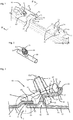
Fig. 1 zeigt in einer vereinfachten und schematischen Perspektivdarstellung ein erstes Bauteil, insbesondere einen Teil einer Strebenverkleidung eines Turbinenzwischengehäuses einer Gasturbine, mit exemplarisch zwei Halteabschnitten und exemplarisch einer Klammer. -
Fig. 2 zeigt in einer vergrößerten schematischen Perspektivdarstellung einer Schraubverbindung der Verbindungsanordnung. -
Fig. 3 zeigt einen schematischen Querschnitt durch die Verbindungsanordnung etwa entsprechend der Schnittlinie III-III derFigur 1 . - Eine Verbindungsanordnung 10, die aus den
Fig. 1 und 3 ersichtlich ist und unter Bezugnahme auf diese beiden Figuren nachfolgend beschrieben wird, umfasst ein erstes Bauteil 12 und ein nur in derFig. 3 gezeigtes zweites Bauteil 14. Die beiden Bauteile 12, 14 sind aus keramischen Faserverbundwerkstoffen bzw. Faserverbundmaterial hergestellt. Das erste Bauteil 12 ist vorzugsweise ein erstes Gehäuseelement, insbesondere ein Fairing bzw. eine Strebenverkleidung eines hier nicht dargestellten Turbinenzwischengehäuses. Das zweite Bauteil ist bevorzugt ein zweites Gehäuseelement, insbesondere ein einen Heißgas führenden Ringkanal begrenzendes Panel des Turbinenzwischengehäuses. - Das erste Bauteil 12 und das zweite Bauteil 14 überlappen sich in einem Verbindungsbereich 16. Dabei liegt ein Überlappungsabschnitt 18 des zweiten Bauteils 14 auf dem Überlappungsabschnitt 20 des ersten Bauteils 12. Im Verbindungsbereich 16 wird durch die Überlappung der beiden Bauteile 12, 14 eine Abdichtung am Übergang zwischen den beiden Bauteilen 12, 14 erreicht.
- Am ersten Bauteil 12 sind in
Fig. 1 zwei Halteabschnitte 22 ersichtlich, die einstückig am ersten Bauteil 12 ausgebildet sind. Der Halteabschnitt 22 weist eine längliche Öffnung 24 auf, die auch als schlitzartige Öffnung bezeichnet werden kann. Der Halteabschnitt 22 weist eine Vorderseite 26 und eine Rückseite 28 auf. In der Öffnung 24 ist eine Schraubverbindung, insbesondere deren Bolzenabschnitt 30 aufgenommen. Der Bolzenabschnitt 30 erstreckt nach oben hin durch eine Öffnung 32 in einer auf dem zweiten Bauteil 14 und dem Halteabschnitt 22 aufliegenden Klammer 34. Der Bolzenabschnitt 30 weist in seinem vom Halteabschnitt 22 abgewandten oberen Teil einen Gewindeabschnitt bzw. ein Außengewinde auf. Mit dem Gewindeabschnitt 36 ist eine Schraubenmutter 38 mit entsprechendem Innengewinde verbindbar. Die Schraubenmutter 38 liegt im festgezogenen Zustand auf der Klammer 34 auf. Die schlitzartige Öffnung 24 kann beispielsweise in den Halteabschnitt 2 gefräst werden. - Damit die Schraubverbindung festgezogen werden kann, weist sie einen mit dem Bolzenabschnitt 30 verbundenen Abstützabschnitt 40 auf, was am besten aus der
Fig. 2 ersichtlich ist. Der Abstützabschnitt 40 ist vorzugsweise geneigt, insbesondere orthogonal zum Bolzenabschnitt 30 bzw. der Schraubverbindungsachse SA ausgeführt. Vorzugsweise sind der Bolzenabschnitt 30 und der Abstützabschnitt 40 einstückig ausgeführt. Der Bolzenabschnitt 30 und der Abstützabschnitt 40 können zusammen auch als T-förmiges Element bezeichnet werden. Beim Festziehen der Schraubenmutter 38 wird die Klammer 34 gegen die Ober- bzw. Vorderseite 26 des Halteabschnitts 22 gedrückt und der Abstützabschnitt 40 wird gegen die Rückseite 28 des Halteabschnitts 22 gedrückt. - Der Halteabschnitt 22 weist auf seiner Vorderseite 26 ausgehend von einem Übergangsbereich 42 einen konvexen Abschnitt 44 und einen konkaven Abschnitt 46 auf. Diese beiden Abschnitte 44, 46 können durch einen geradlinigen Abschnitt 48 miteinander verbunden sein. Auf seiner Rückseite 28 weist der Halteabschnitt 22 ausgehend vom Übergangsbereich 42 einen konkaven Abschnitt 50 und einen konvexen Abschnitt 52 auf. Im konkaven Abschnitt 50 auf der Rückseite des Halteabschnitts 22 ist der Abstützabschnitt 40 der Schraubverbindung aufgenommen. Der Abstützabschnitt 40 weist vorzugsweise einen kreisförmigen Querschnitt auf, so dass er mit einem Teil seiner zylindrischen Außenfläche an dem konkaven Abschnitt 50 der Rückseite des Halteabschnitts 22 anliegt. Bevorzugt ist der Krümmungsradius des konkaven Abschnitts 50 im Wesentlichen gleich groß wie der Radius des kreisförmigen Querschnitts des Abstützabschnitts.
- Die Klammer 34 weist einen dem Halteabschnitt 22 des ersten Bauteils 12 zugewandten ersten Auflageabschnitt 54 auf mit einer auf dem ersten Bauteil 12, insbesondere dem konkaven Abschnitt 46 der Vorderseite 26 aufliegenden ersten Klemmfläche 56. Die erste Klemmfläche 56 ist vorzugsweise gekrümmt, insbesondere ist sie konvex ausgebildet. Durch die im Wesentlichen komplementäre Ausgestaltung der ersten Klemmfläche 56 und des konkaven Abschnitts 56 der Vorderseite 26 des Halteabschnitts 22 ergibt sich auch eine formschlüssige Verbindung zwischen der Klammer 34 und dem Halteabschnitt 22. Im verbundenen Zustand ist die Klammer 34 dadurch sicher am Halteabschnitt abgestützt. Ferner weist die Klammer 34 einen dem Verbindungsbereich zugwandten zweiten Auflageabschnitt 58 auf mit einer auf dem zweiten Bauteil 14 aufliegenden zweiten Klemmfläche 60. Die zweite Klemmfläche 60 ist vorzugsweise im Wesentlichen eben ausgebildet. Die Klammer 34 weist ferner einen den ersten Auflageabschnitt 54 und den zweiten Auflageabschnitt 58 verbindenden Zentralabschnitt 62 auf. Der Zentralabschnitt 62 hat vorzugsweise eine vom Halteabschnitt 22 abgewandte Oberseite, die im Wesentlichen eben ausgeführt ist.
- Im verbundenen Zustand wird im Verbindungsbereich 16 der Überlappungsabschnitt 20 des ersten Bauteils in Richtung des zweiten Auflageabschnitts 58 der Klammer 34 gedrückt bzw. gezogen. Hierdurch wird der Überlappungsabschnitt 18 des zweiten Bauteils 14 zwischen dem Überlappungsabschnitt 20 und dem Auflageabschnitt 58 aufgenommen und festgeklemmt. Aufgrund der wirkenden Klemmkräfte wird zwischen dem ersten Bauteil 12 und dem zweiten Bauteil 14 eine dichte Verbindung ermöglicht. Der Halteabschnitt 22 dient dabei auch als eine Art Biegebalken, um beim Festklemmen bzw. beim Verspannen der Verbindungsanordnung eine ausreichende Deformation zu erreichen, so dass im Verbindungsbereich 16 eine gewünschte Dichtigkeit erhalten werden kann, insbesondere auch unter dem Einfluss von Verschleiß oder thermischen Verformungen.
- Aus der
Fig. 3 ist ferner rein schematisch ersichtlich, dass Faserlagen FL des Halteabschnitts 22 durchlaufend gelegt sind. Diese durchlaufenden Faserlagen geben dem Halteabschnitt 22 die erforderliche Stabilität und Elastizität, um die gewünschte Klemmwirkung bzw. Verspannung der Verbindungsanordnung 10 zu erreichen. - Durch die hier vorgestellte Verbindungsanordnung kann die gleiche Klemmwirkung erreicht werden, wie bei einer bekannten Variante mit angelötetem Stehbolzen. Da die Komponenten der Verbindungsanordnung nur gegeneinander verspannt sind und keine materialschlüssige Verbindung (z.B: Löten) notwendig ist, können mit dieser Verbindungsanordnung CMC-Bauteile aneinander befestigt werden.
- Sind das erste Bauteil 12 und das zweite Bauteil 14 Gehäuseelemente eines Heißgas führenden Ringkanals eines Turbinenzwischengehäuses einer Gasturbine, kann durch die vorgestellte Verbindungsanordnung erreicht werden, dass keine metallischen Bauteile mit dem Ringkanal in Kontakt stehen, also nicht mit Heißgas benetzt werden. Metallische Bauteile, wie etwa die Schraubverbindung und die Klammer sind außerhalb des Ringkanals angeordnet und lediglich der Sperrluft ausgesetzt. Wenn keine metallischen Bauteile im Ringkanal vorhanden sind, kann auch die Temperatur des Heißgases erhöht werden.
- Insgesamt ergibt sich eine sehr einfache und kostengünstig herstellbare Verbindungsanordnung für zwei Bauteile aus keramischen Faserverbundwerkstoffen. Zwei solche Bauteile können auch mittels mehrerer solcher Verbindungsanordnungen miteinander verbunden werden, wie dies auch in der
Fig. 1 angedeutet ist. -
- 10
- Verbindungsanordnung
- 12
- erstes Bauteil / erstes Gehäuseelement
- 14
- zweites Bauteil / zweites Gehäuseelement
- 16
- Verbindungsbereich
- 18
- Überlappungsabschnitt des ersten Bauteils
- 20
- Überlappungsabschnitt des zweiten Bauteils
- 22
- Halteabschnitt
- 24
- längliche Öffnung
- 26
- Vorderseite des Halteabschnitts
- 28
- Rückseite des Halteabschnitts
- 30
- Bolzenabschnitt
- 32
- Öffnung der Klammer
- 34
- Klammer
- 36
- Gewindeabschnitt
- 38
- Schraubenmutter
- 40
- Abstützabschnitt
- 42
- Übergangsbereich
- 44
- konvexer Abschnitt der Vorderseite
- 46
- konkaver Abschnitt der Vorderseite
- 48
- geradliniger Abschnitt
- 50
- konkaver Abschnitt der Rückseite
- 52
- konvexer Abschnitt der Rückseite
- 54
- erster Auflageabschnitt
- 56
- erste Klemmfläche
- 58
- zweiter Auflageabschnitt
- 60
- zweite Klemmfläche
- 62
- Zentralabschnitt
Claims (11)
- Verbindungsanordnung (10) umfassend
ein erstes Bauteil (12) und ein zweites Bauteil (14), wobei das erste Bauteil (12) und das zweite Bauteil (14) in einem Verbindungsbereich (16, 18, 20) überlappend zueinander angeordnet sind;
ein Verbindungsmittel, das mit dem ersten Bauteil (12) und dem zweiten Bauteil (14) derart in Kontakt steht, dass das erste Bauteil (12) und das zweite Bauteil (14) im Verbindungsbereich (16) klemmend aneinander anliegen, wobei das Verbindungsmittel eine am ersten Bauteil (12) und am zweite Bauteil (14) aufliegende Klammer (34) umfasst und eine Schraubverbindung (30, 38, 40) aufweist, die dazu eingerichtet ist, die Klammer (34) am ersten und am zweiten Bauteil (12, 14) zu fixieren,
dadurch gekennzeichnet, dass das erste Bauteil (12) und das zweite Bauteil (14) aus einem keramischen Faserverbundmaterial (CMC) hergestellt sind, wobei das erste Bauteil (12) einen Halteabschnitt (22) aufweist mit einer der Klammer (34) zugewandten Vorderseite (26), einer von der Klammer abgewandten Rückseite (28) und einer Aufnahmeöffnung (24), und dass die Schraubverbindung (30, 38, 40) einen durch die Aufnahmeöffnung (24) hindurchgehenden Bolzenabschnitt (30) aufweist, der an seinem von der Klammer (34) abgewandten Ende einen zur Längsachse (SA) des Bolzenabschnitts (30) geneigt, insbesondere orthogonal verlaufenden Abstützabschnitt (40) aufweist, der an der Rückseite (28) des Halteabschnitts (22) anliegt. - Verbindungsanordnung nach Anspruch 1, dadurch gekennzeichnet, dass der Halteabschnitt (22) entlang seiner Vorderseite (26) einen konvexen Abschnitt (44) und einen konkaven Abschnitt (46) aufweist, wobei die Klammer (34) an dem konkaven Abschnitt (46) der Vorderseite (26) abgestützt ist.
- Verbindungsanordnung nach Anspruch 1 oder 2, dadurch gekennzeichnet, dass der Halteabschnitt (22) entlang seiner Rückseite (28) einen konkaven Abschnitt (50) und einen konvexen Abschnitt (52) aufweist, wobei der Abstützabschnitt (40) der Schraubverbindung an dem konkaven Abschnitt (50) der Rückseite (28) abgestützt ist.
- Verbindungsanordnung nach einem der vorhergehenden Ansprüche, dadurch gekennzeichnet, dass die Öffnung (24) des Halteabschnitts (22) schlitzartig ausgeführt ist mit einem offenen Ende, derart dass der Bolzenabschnitt (30) durch das offene Ende in die schlitzartige Öffnung (24) einführbar ist.
- Verbindungsanordnung nach einem der vorhergehenden Ansprüche, dadurch gekennzeichnet, dass die Klammer (34) einen dem Halteabschnitt (22) des ersten Bauteils (12) zugewandten ersten Auflageabschnitt (54) aufweist mit einer auf dem ersten Bauteil (12), insbesondere dem konkaven Abschnitt (46) der Vorderseite (26) aufliegenden ersten Klemmfläche (56), wobei die erste Klemmfläche (56) vorzugsweise gekrümmt, insbesondere konvex ausgebildet ist.
- Verbindungsanordnung nach einem der vorhergehenden Ansprüche, dadurch gekennzeichnet, dass die Klammer (34) einen dem Verbindungsbereich (16) zugwandten zweiten Auflageabschnitt (58) aufweist mit einer auf dem zweiten Bauteil (14) aufliegenden zweiten Klemmfläche (60), wobei die zweite Klemmfläche (60) vorzugsweise im Wesentlichen eben ausgebildet ist.
- Verbindungsanordnung nach Anspruch 5 und 6, dadurch gekennzeichnet, dass die Klammer (34) einen den ersten Auflageabschnitt (54) und den zweiten Auflageabschnitt (58) verbindenden Zentralabschnitt (62) aufweist, wobei der Zentralabschnitt (62) eine vom Halteabschnitt (22) abgewandte Oberseite aufweist, die im Wesentlichen eben ausgeführt ist.
- Verbindungsanordnung nach einem der vorhergehenden Ansprüche, dadurch gekennzeichnet, dass im Halteabschnitt (22) Faserlagen (FL) des Keramikfaserverbundmaterials (CMC) durchlaufend gelegt sind.
- Turbinenzwischengehäuse einer Gasturbine, insbesondere Fluggasturbine, mit einem Heißgas führenden Ringkanal, umfassend
wenigstens ein erstes Gehäuseelement, insbesondere ein Fairing des Turbinenzwischengehäuses,
wenigstens ein zweites Gehäuseelement, insbesondere ein Panel eines Turbinenzwischengehäuses,
dadurch gekennzeichnet dass es
wenigstens eine Verbindungsanordnung (10) nach einem der vorhergehenden Ansprüche aufweist, wobei das erste Gehäuseelement das erste Bauteil (12) aus keramischem Faserverbundmaterial (CMC) bildet und das zweite Gehäuseelement das zweite Bauteil (14) aus keramischem Faserverbundmaterial (CMC) bildet. - Turbinenzwischengehäuse nach Anspruch 9, dadurch gekennzeichnet, dass der Verbindungsbereich (16) zwischen dem ersten Gehäuseelement (12) und dem zweiten Gehäuseelement (14) den Heißgas führenden Ringkanal abdichtet.
- Gasturbine, insbesondere Fluggasturbine, mit einem Turbinenzwischengehäuse nach einem der Ansprüche 9 oder 10.
Priority Applications (3)
| Application Number | Priority Date | Filing Date | Title |
|---|---|---|---|
| ES16163769.9T ES2684672T3 (es) | 2016-04-05 | 2016-04-05 | Disposición de unión para componentes de materiales de trabajo compuestos reforzados con fibras cerámicos de una carcasa intermedia de turbina |
| EP16163769.9A EP3228833B1 (de) | 2016-04-05 | 2016-04-05 | Verbindungsanordnung für bauteile aus keramischen faserverbundwerkstoffen eines turbinenzwischengehäuses |
| US15/479,498 US10415430B2 (en) | 2016-04-05 | 2017-04-05 | Coupling assembly for components of ceramic matrix composites for a turbine center frame |
Applications Claiming Priority (1)
| Application Number | Priority Date | Filing Date | Title |
|---|---|---|---|
| EP16163769.9A EP3228833B1 (de) | 2016-04-05 | 2016-04-05 | Verbindungsanordnung für bauteile aus keramischen faserverbundwerkstoffen eines turbinenzwischengehäuses |
Publications (2)
| Publication Number | Publication Date |
|---|---|
| EP3228833A1 true EP3228833A1 (de) | 2017-10-11 |
| EP3228833B1 EP3228833B1 (de) | 2018-08-01 |
Family
ID=55697052
Family Applications (1)
| Application Number | Title | Priority Date | Filing Date |
|---|---|---|---|
| EP16163769.9A Not-in-force EP3228833B1 (de) | 2016-04-05 | 2016-04-05 | Verbindungsanordnung für bauteile aus keramischen faserverbundwerkstoffen eines turbinenzwischengehäuses |
Country Status (3)
| Country | Link |
|---|---|
| US (1) | US10415430B2 (de) |
| EP (1) | EP3228833B1 (de) |
| ES (1) | ES2684672T3 (de) |
Families Citing this family (2)
| Publication number | Priority date | Publication date | Assignee | Title |
|---|---|---|---|---|
| DE102016117960A1 (de) * | 2016-09-23 | 2018-03-29 | Man Diesel & Turbo Se | Turbolader |
| US20260071552A1 (en) * | 2024-09-06 | 2026-03-12 | Rtx Corporation | Lap jointed longitudinal/axial flanges for circumferentially flanged composite components in the form of hollow single/multi-cylinders, single/multi-angle conical frustrums or a combination thereof |
Citations (5)
| Publication number | Priority date | Publication date | Assignee | Title |
|---|---|---|---|---|
| EP1607582A1 (de) * | 2004-06-17 | 2005-12-21 | Snecma Moteurs | Aufhängung einer Gasturbinenbrennkammer mit integriertem Turbinenleitapparat |
| US20110008163A1 (en) * | 2009-07-08 | 2011-01-13 | Ian Francis Prentice | Composite article and support frame assembly |
| EP2604805A2 (de) * | 2011-12-15 | 2013-06-19 | General Electric Company | Statoraussenringanordnung für ein Gasturbinentriebwerk |
| WO2015031764A1 (en) * | 2013-08-29 | 2015-03-05 | United Technologies Corporation | Blade outer air seal made of ceramic matrix composite |
| WO2015065563A2 (en) * | 2013-08-22 | 2015-05-07 | United Technologies Corporation | Connection for a fairing in a mid-turbine frame of a gas turbine engine |
Family Cites Families (11)
| Publication number | Priority date | Publication date | Assignee | Title |
|---|---|---|---|---|
| US1676289A (en) * | 1927-01-12 | 1928-07-10 | Schmalz Albano | Machinist's work clamp |
| FR2305541A1 (fr) * | 1975-03-26 | 1976-10-22 | Vagneux Traverses Beton Arme S | Perfectionnements aux ensembles pour la fixation d'un rail sur une traverse par serrage mesure d'un boulon |
| DE2944671A1 (de) * | 1979-11-06 | 1981-05-27 | Strohm + Maier, Labormöbel GmbH, 7920 Heidenheim | Zahntechnischer laborarbeitsplatz |
| DE20116015U1 (de) | 2001-04-12 | 2002-03-07 | LISEGA GmbH, 27404 Zeven | Klemmvorrichtung zum Klemmen von Trägern |
| US6648597B1 (en) * | 2002-05-31 | 2003-11-18 | Siemens Westinghouse Power Corporation | Ceramic matrix composite turbine vane |
| GB0700818D0 (en) | 2007-01-16 | 2007-02-21 | Tyco Europe Metal Framing Ltd | Clamp head |
| US8061977B2 (en) | 2007-07-03 | 2011-11-22 | Siemens Energy, Inc. | Ceramic matrix composite attachment apparatus and method |
| GB0802938D0 (en) | 2008-02-19 | 2008-03-26 | Airbus Uk Ltd | Clamped friction joint |
| EP2784333B1 (de) | 2013-03-28 | 2018-03-21 | MTU Aero Engines GmbH | Vorrichtung zum Positionieren und Verspannen von zwei konzentrischen, einander teilweise überlappenden Bauteilen |
| DE102014210182A1 (de) | 2014-03-05 | 2015-10-22 | MTU Aero Engines AG | Gasturbinenkanalgehäuse |
| ES2637944T3 (es) | 2014-06-06 | 2017-10-18 | MTU Aero Engines AG | Disposición de los componentes de una turbina de gas |
-
2016
- 2016-04-05 ES ES16163769.9T patent/ES2684672T3/es active Active
- 2016-04-05 EP EP16163769.9A patent/EP3228833B1/de not_active Not-in-force
-
2017
- 2017-04-05 US US15/479,498 patent/US10415430B2/en not_active Expired - Fee Related
Patent Citations (5)
| Publication number | Priority date | Publication date | Assignee | Title |
|---|---|---|---|---|
| EP1607582A1 (de) * | 2004-06-17 | 2005-12-21 | Snecma Moteurs | Aufhängung einer Gasturbinenbrennkammer mit integriertem Turbinenleitapparat |
| US20110008163A1 (en) * | 2009-07-08 | 2011-01-13 | Ian Francis Prentice | Composite article and support frame assembly |
| EP2604805A2 (de) * | 2011-12-15 | 2013-06-19 | General Electric Company | Statoraussenringanordnung für ein Gasturbinentriebwerk |
| WO2015065563A2 (en) * | 2013-08-22 | 2015-05-07 | United Technologies Corporation | Connection for a fairing in a mid-turbine frame of a gas turbine engine |
| WO2015031764A1 (en) * | 2013-08-29 | 2015-03-05 | United Technologies Corporation | Blade outer air seal made of ceramic matrix composite |
Also Published As
| Publication number | Publication date |
|---|---|
| ES2684672T3 (es) | 2018-10-04 |
| US20170298774A1 (en) | 2017-10-19 |
| US10415430B2 (en) | 2019-09-17 |
| EP3228833B1 (de) | 2018-08-01 |
Similar Documents
| Publication | Publication Date | Title |
|---|---|---|
| DE102012009090A1 (de) | Anbindung eines doppelwandigen Turboladergehäuses | |
| EP3079975B1 (de) | Trägerkonstruktion in fachwerkbauweise und verfahren zu deren herstellung | |
| EP3385506B1 (de) | Dichtungsanordnung für eine gasturbine | |
| EP3181975A1 (de) | Verbindungseinichtung zwischen einem turbinengeäuse eines abgastrurboladers und einem anschlussghäuse | |
| DE102007002825A1 (de) | Klemmflanschanordnung zum Anschluss einer Auspuffanlage an eine Brennkraftmaschine | |
| DE102011112633B4 (de) | Abgasrohrbaugruppe sowie Verfahren zur Befestigung eines Befestigungsblechs an einem Abgasrohr | |
| DE29700666U1 (de) | Rohrpreßkupplung | |
| EP3228833B1 (de) | Verbindungsanordnung für bauteile aus keramischen faserverbundwerkstoffen eines turbinenzwischengehäuses | |
| DE102018131671A1 (de) | Spannschelle und Abgasturbolader mit einer solchen Spannschelle | |
| EP1834101B1 (de) | Klammer zum verbinden eines anbaukörpers mit einem grundkörper | |
| DE102010053078A1 (de) | Abgasturbolader | |
| EP2492517A1 (de) | Verbindungsanordnung für Bambusrohre | |
| DE102010032319A1 (de) | Flanschverbindung | |
| DE102014011606B4 (de) | Abgassystem für eine Brennkraftmaschine | |
| DE2129145B2 (de) | Loesbares kugelgelenk zum verbinden von gestaengeteilen | |
| EP4141308B1 (de) | Rohrverbindungsanordnung | |
| DE102016103546A1 (de) | Rohrverbinder und System mit Schalenelementen | |
| DE19728815C2 (de) | Rohrverbindung zweier sich überlappender Rohre | |
| EP1329608A2 (de) | Abgasanlage für Kraftfahrzeuge | |
| DE1937975B2 (de) | Druckleitungsverbindung mit druckleitungsnippel gegenstueck und ueberwurfmutter | |
| WO2013171681A1 (de) | Rohrkupplung insbesondere zur dichtenden verbindung glattendiger rohre | |
| WO2010034823A1 (de) | Strahlrohranordnung mit einer verbindungseinrichtung | |
| EP2982807B1 (de) | Vorrichtung zum Verbinden von zwei durch eine Fuge getrennten Bauteilen | |
| DE202010012664U1 (de) | Abgasanlagen-Verbindungsstück | |
| DE2651286C2 (de) | Haltevorrichtung für ein vorzugsweise im Querschnitt rechteckiges Rohr an einer Platte eines Wärmetauschers |
Legal Events
| Date | Code | Title | Description |
|---|---|---|---|
| PUAI | Public reference made under article 153(3) epc to a published international application that has entered the european phase |
Free format text: ORIGINAL CODE: 0009012 |
|
| STAA | Information on the status of an ep patent application or granted ep patent |
Free format text: STATUS: THE APPLICATION HAS BEEN PUBLISHED |
|
| AK | Designated contracting states |
Kind code of ref document: A1 Designated state(s): AL AT BE BG CH CY CZ DE DK EE ES FI FR GB GR HR HU IE IS IT LI LT LU LV MC MK MT NL NO PL PT RO RS SE SI SK SM TR |
|
| AX | Request for extension of the european patent |
Extension state: BA ME |
|
| STAA | Information on the status of an ep patent application or granted ep patent |
Free format text: STATUS: REQUEST FOR EXAMINATION WAS MADE |
|
| 17P | Request for examination filed |
Effective date: 20180328 |
|
| RBV | Designated contracting states (corrected) |
Designated state(s): AL AT BE BG CH CY CZ DE DK EE ES FI FR GB GR HR HU IE IS IT LI LT LU LV MC MK MT NL NO PL PT RO RS SE SI SK SM TR |
|
| RIC1 | Information provided on ipc code assigned before grant |
Ipc: F01D 25/00 20060101AFI20180420BHEP Ipc: F01D 25/24 20060101ALI20180420BHEP |
|
| GRAP | Despatch of communication of intention to grant a patent |
Free format text: ORIGINAL CODE: EPIDOSNIGR1 |
|
| STAA | Information on the status of an ep patent application or granted ep patent |
Free format text: STATUS: GRANT OF PATENT IS INTENDED |
|
| GRAS | Grant fee paid |
Free format text: ORIGINAL CODE: EPIDOSNIGR3 |
|
| INTG | Intention to grant announced |
Effective date: 20180601 |
|
| GRAA | (expected) grant |
Free format text: ORIGINAL CODE: 0009210 |
|
| STAA | Information on the status of an ep patent application or granted ep patent |
Free format text: STATUS: THE PATENT HAS BEEN GRANTED |
|
| AK | Designated contracting states |
Kind code of ref document: B1 Designated state(s): AL AT BE BG CH CY CZ DE DK EE ES FI FR GB GR HR HU IE IS IT LI LT LU LV MC MK MT NL NO PL PT RO RS SE SI SK SM TR |
|
| REG | Reference to a national code |
Ref country code: GB Ref legal event code: FG4D Free format text: NOT ENGLISH |
|
| REG | Reference to a national code |
Ref country code: CH Ref legal event code: EP Ref country code: AT Ref legal event code: REF Ref document number: 1024547 Country of ref document: AT Kind code of ref document: T Effective date: 20180815 |
|
| REG | Reference to a national code |
Ref country code: IE Ref legal event code: FG4D Free format text: LANGUAGE OF EP DOCUMENT: GERMAN |
|
| REG | Reference to a national code |
Ref country code: DE Ref legal event code: R096 Ref document number: 502016001558 Country of ref document: DE |
|
| REG | Reference to a national code |
Ref country code: ES Ref legal event code: FG2A Ref document number: 2684672 Country of ref document: ES Kind code of ref document: T3 Effective date: 20181004 |
|
| REG | Reference to a national code |
Ref country code: NL Ref legal event code: MP Effective date: 20180801 |
|
| REG | Reference to a national code |
Ref country code: LT Ref legal event code: MG4D |
|
| PG25 | Lapsed in a contracting state [announced via postgrant information from national office to epo] |
Ref country code: NO Free format text: LAPSE BECAUSE OF FAILURE TO SUBMIT A TRANSLATION OF THE DESCRIPTION OR TO PAY THE FEE WITHIN THE PRESCRIBED TIME-LIMIT Effective date: 20181101 Ref country code: SE Free format text: LAPSE BECAUSE OF FAILURE TO SUBMIT A TRANSLATION OF THE DESCRIPTION OR TO PAY THE FEE WITHIN THE PRESCRIBED TIME-LIMIT Effective date: 20180801 Ref country code: BG Free format text: LAPSE BECAUSE OF FAILURE TO SUBMIT A TRANSLATION OF THE DESCRIPTION OR TO PAY THE FEE WITHIN THE PRESCRIBED TIME-LIMIT Effective date: 20181101 Ref country code: RS Free format text: LAPSE BECAUSE OF FAILURE TO SUBMIT A TRANSLATION OF THE DESCRIPTION OR TO PAY THE FEE WITHIN THE PRESCRIBED TIME-LIMIT Effective date: 20180801 Ref country code: IS Free format text: LAPSE BECAUSE OF FAILURE TO SUBMIT A TRANSLATION OF THE DESCRIPTION OR TO PAY THE FEE WITHIN THE PRESCRIBED TIME-LIMIT Effective date: 20181201 Ref country code: GR Free format text: LAPSE BECAUSE OF FAILURE TO SUBMIT A TRANSLATION OF THE DESCRIPTION OR TO PAY THE FEE WITHIN THE PRESCRIBED TIME-LIMIT Effective date: 20181102 Ref country code: FI Free format text: LAPSE BECAUSE OF FAILURE TO SUBMIT A TRANSLATION OF THE DESCRIPTION OR TO PAY THE FEE WITHIN THE PRESCRIBED TIME-LIMIT Effective date: 20180801 Ref country code: PL Free format text: LAPSE BECAUSE OF FAILURE TO SUBMIT A TRANSLATION OF THE DESCRIPTION OR TO PAY THE FEE WITHIN THE PRESCRIBED TIME-LIMIT Effective date: 20180801 Ref country code: LT Free format text: LAPSE BECAUSE OF FAILURE TO SUBMIT A TRANSLATION OF THE DESCRIPTION OR TO PAY THE FEE WITHIN THE PRESCRIBED TIME-LIMIT Effective date: 20180801 Ref country code: NL Free format text: LAPSE BECAUSE OF FAILURE TO SUBMIT A TRANSLATION OF THE DESCRIPTION OR TO PAY THE FEE WITHIN THE PRESCRIBED TIME-LIMIT Effective date: 20180801 |
|
| PG25 | Lapsed in a contracting state [announced via postgrant information from national office to epo] |
Ref country code: HR Free format text: LAPSE BECAUSE OF FAILURE TO SUBMIT A TRANSLATION OF THE DESCRIPTION OR TO PAY THE FEE WITHIN THE PRESCRIBED TIME-LIMIT Effective date: 20180801 Ref country code: LV Free format text: LAPSE BECAUSE OF FAILURE TO SUBMIT A TRANSLATION OF THE DESCRIPTION OR TO PAY THE FEE WITHIN THE PRESCRIBED TIME-LIMIT Effective date: 20180801 Ref country code: AL Free format text: LAPSE BECAUSE OF FAILURE TO SUBMIT A TRANSLATION OF THE DESCRIPTION OR TO PAY THE FEE WITHIN THE PRESCRIBED TIME-LIMIT Effective date: 20180801 |
|
| PG25 | Lapsed in a contracting state [announced via postgrant information from national office to epo] |
Ref country code: RO Free format text: LAPSE BECAUSE OF FAILURE TO SUBMIT A TRANSLATION OF THE DESCRIPTION OR TO PAY THE FEE WITHIN THE PRESCRIBED TIME-LIMIT Effective date: 20180801 Ref country code: CZ Free format text: LAPSE BECAUSE OF FAILURE TO SUBMIT A TRANSLATION OF THE DESCRIPTION OR TO PAY THE FEE WITHIN THE PRESCRIBED TIME-LIMIT Effective date: 20180801 Ref country code: IT Free format text: LAPSE BECAUSE OF FAILURE TO SUBMIT A TRANSLATION OF THE DESCRIPTION OR TO PAY THE FEE WITHIN THE PRESCRIBED TIME-LIMIT Effective date: 20180801 Ref country code: EE Free format text: LAPSE BECAUSE OF FAILURE TO SUBMIT A TRANSLATION OF THE DESCRIPTION OR TO PAY THE FEE WITHIN THE PRESCRIBED TIME-LIMIT Effective date: 20180801 |
|
| REG | Reference to a national code |
Ref country code: DE Ref legal event code: R097 Ref document number: 502016001558 Country of ref document: DE |
|
| PG25 | Lapsed in a contracting state [announced via postgrant information from national office to epo] |
Ref country code: SK Free format text: LAPSE BECAUSE OF FAILURE TO SUBMIT A TRANSLATION OF THE DESCRIPTION OR TO PAY THE FEE WITHIN THE PRESCRIBED TIME-LIMIT Effective date: 20180801 Ref country code: SM Free format text: LAPSE BECAUSE OF FAILURE TO SUBMIT A TRANSLATION OF THE DESCRIPTION OR TO PAY THE FEE WITHIN THE PRESCRIBED TIME-LIMIT Effective date: 20180801 Ref country code: DK Free format text: LAPSE BECAUSE OF FAILURE TO SUBMIT A TRANSLATION OF THE DESCRIPTION OR TO PAY THE FEE WITHIN THE PRESCRIBED TIME-LIMIT Effective date: 20180801 |
|
| PLBE | No opposition filed within time limit |
Free format text: ORIGINAL CODE: 0009261 |
|
| STAA | Information on the status of an ep patent application or granted ep patent |
Free format text: STATUS: NO OPPOSITION FILED WITHIN TIME LIMIT |
|
| 26N | No opposition filed |
Effective date: 20190503 |
|
| PG25 | Lapsed in a contracting state [announced via postgrant information from national office to epo] |
Ref country code: SI Free format text: LAPSE BECAUSE OF FAILURE TO SUBMIT A TRANSLATION OF THE DESCRIPTION OR TO PAY THE FEE WITHIN THE PRESCRIBED TIME-LIMIT Effective date: 20180801 |
|
| REG | Reference to a national code |
Ref country code: CH Ref legal event code: PL |
|
| REG | Reference to a national code |
Ref country code: BE Ref legal event code: MM Effective date: 20190430 |
|
| PG25 | Lapsed in a contracting state [announced via postgrant information from national office to epo] |
Ref country code: MC Free format text: LAPSE BECAUSE OF FAILURE TO SUBMIT A TRANSLATION OF THE DESCRIPTION OR TO PAY THE FEE WITHIN THE PRESCRIBED TIME-LIMIT Effective date: 20180801 Ref country code: LU Free format text: LAPSE BECAUSE OF NON-PAYMENT OF DUE FEES Effective date: 20190405 |
|
| PG25 | Lapsed in a contracting state [announced via postgrant information from national office to epo] |
Ref country code: LI Free format text: LAPSE BECAUSE OF NON-PAYMENT OF DUE FEES Effective date: 20190430 Ref country code: CH Free format text: LAPSE BECAUSE OF NON-PAYMENT OF DUE FEES Effective date: 20190430 |
|
| PG25 | Lapsed in a contracting state [announced via postgrant information from national office to epo] |
Ref country code: BE Free format text: LAPSE BECAUSE OF NON-PAYMENT OF DUE FEES Effective date: 20190430 |
|
| PG25 | Lapsed in a contracting state [announced via postgrant information from national office to epo] |
Ref country code: TR Free format text: LAPSE BECAUSE OF FAILURE TO SUBMIT A TRANSLATION OF THE DESCRIPTION OR TO PAY THE FEE WITHIN THE PRESCRIBED TIME-LIMIT Effective date: 20180801 |
|
| PG25 | Lapsed in a contracting state [announced via postgrant information from national office to epo] |
Ref country code: IE Free format text: LAPSE BECAUSE OF NON-PAYMENT OF DUE FEES Effective date: 20190405 |
|
| PG25 | Lapsed in a contracting state [announced via postgrant information from national office to epo] |
Ref country code: PT Free format text: LAPSE BECAUSE OF FAILURE TO SUBMIT A TRANSLATION OF THE DESCRIPTION OR TO PAY THE FEE WITHIN THE PRESCRIBED TIME-LIMIT Effective date: 20181201 |
|
| PG25 | Lapsed in a contracting state [announced via postgrant information from national office to epo] |
Ref country code: CY Free format text: LAPSE BECAUSE OF FAILURE TO SUBMIT A TRANSLATION OF THE DESCRIPTION OR TO PAY THE FEE WITHIN THE PRESCRIBED TIME-LIMIT Effective date: 20180801 |
|
| PG25 | Lapsed in a contracting state [announced via postgrant information from national office to epo] |
Ref country code: MT Free format text: LAPSE BECAUSE OF FAILURE TO SUBMIT A TRANSLATION OF THE DESCRIPTION OR TO PAY THE FEE WITHIN THE PRESCRIBED TIME-LIMIT Effective date: 20180801 Ref country code: HU Free format text: LAPSE BECAUSE OF FAILURE TO SUBMIT A TRANSLATION OF THE DESCRIPTION OR TO PAY THE FEE WITHIN THE PRESCRIBED TIME-LIMIT; INVALID AB INITIO Effective date: 20160405 |
|
| PGFP | Annual fee paid to national office [announced via postgrant information from national office to epo] |
Ref country code: DE Payment date: 20210421 Year of fee payment: 6 Ref country code: FR Payment date: 20210421 Year of fee payment: 6 |
|
| PGFP | Annual fee paid to national office [announced via postgrant information from national office to epo] |
Ref country code: ES Payment date: 20210519 Year of fee payment: 6 Ref country code: GB Payment date: 20210422 Year of fee payment: 6 |
|
| REG | Reference to a national code |
Ref country code: AT Ref legal event code: MM01 Ref document number: 1024547 Country of ref document: AT Kind code of ref document: T Effective date: 20210405 |
|
| PG25 | Lapsed in a contracting state [announced via postgrant information from national office to epo] |
Ref country code: MK Free format text: LAPSE BECAUSE OF FAILURE TO SUBMIT A TRANSLATION OF THE DESCRIPTION OR TO PAY THE FEE WITHIN THE PRESCRIBED TIME-LIMIT Effective date: 20180801 |
|
| PG25 | Lapsed in a contracting state [announced via postgrant information from national office to epo] |
Ref country code: AT Free format text: LAPSE BECAUSE OF NON-PAYMENT OF DUE FEES Effective date: 20210405 |
|
| REG | Reference to a national code |
Ref country code: DE Ref legal event code: R119 Ref document number: 502016001558 Country of ref document: DE |
|
| GBPC | Gb: european patent ceased through non-payment of renewal fee |
Effective date: 20220405 |
|
| PG25 | Lapsed in a contracting state [announced via postgrant information from national office to epo] |
Ref country code: GB Free format text: LAPSE BECAUSE OF NON-PAYMENT OF DUE FEES Effective date: 20220405 Ref country code: FR Free format text: LAPSE BECAUSE OF NON-PAYMENT OF DUE FEES Effective date: 20220430 Ref country code: DE Free format text: LAPSE BECAUSE OF NON-PAYMENT OF DUE FEES Effective date: 20221103 |
|
| REG | Reference to a national code |
Ref country code: ES Ref legal event code: FD2A Effective date: 20230526 |
|
| PG25 | Lapsed in a contracting state [announced via postgrant information from national office to epo] |
Ref country code: ES Free format text: LAPSE BECAUSE OF NON-PAYMENT OF DUE FEES Effective date: 20220406 |