EP3228794B1 - Profile for frames of doors, wall elements or windows - Google Patents
Profile for frames of doors, wall elements or windows Download PDFInfo
- Publication number
- EP3228794B1 EP3228794B1 EP16163879.6A EP16163879A EP3228794B1 EP 3228794 B1 EP3228794 B1 EP 3228794B1 EP 16163879 A EP16163879 A EP 16163879A EP 3228794 B1 EP3228794 B1 EP 3228794B1
- Authority
- EP
- European Patent Office
- Prior art keywords
- profile
- reflector plate
- reflector
- profile according
- webs
- Prior art date
- Legal status (The legal status is an assumption and is not a legal conclusion. Google has not performed a legal analysis and makes no representation as to the accuracy of the status listed.)
- Active
Links
Images


Classifications
-
- E—FIXED CONSTRUCTIONS
- E06—DOORS, WINDOWS, SHUTTERS, OR ROLLER BLINDS IN GENERAL; LADDERS
- E06B—FIXED OR MOVABLE CLOSURES FOR OPENINGS IN BUILDINGS, VEHICLES, FENCES OR LIKE ENCLOSURES IN GENERAL, e.g. DOORS, WINDOWS, BLINDS, GATES
- E06B3/00—Window sashes, door leaves, or like elements for closing wall or like openings; Layout of fixed or moving closures, e.g. windows in wall or like openings; Features of rigidly-mounted outer frames relating to the mounting of wing frames
- E06B3/04—Wing frames not characterised by the manner of movement
- E06B3/263—Frames with special provision for insulation
- E06B3/26301—Frames with special provision for insulation with prefabricated insulating strips between two metal section members
- E06B3/26303—Frames with special provision for insulation with prefabricated insulating strips between two metal section members with thin strips, e.g. defining a hollow space between the metal section members
Definitions
- the invention relates to a profile for frames of doors, wall elements or windows.
- Known profiles include an upper part and a lower part, which are usually designed as a cavity profile.
- upper part and lower part are usually connected to each other by means of insulating webs made of a plastic. It is also known to improve the insulating properties of the composite profile to equip the insulating bars with transverse surfaces, which reduce heat losses through convection and heat radiation, such as in the DE 295 20 444 U1 or EP 2 256 280 A2 shown.
- From the EP 1 510 643 A1 is a profile for frames of wall elements, doors or windows with a top and a base known.
- Upper part and lower part are connected via side walls with each other, wherein the side walls are inclined de webs, which reduce heat conduction.
- the inventive profile comprises an upper part and a lower part, each with an outer wall.
- Upper part and lower part can but also be designed differently.
- Upper part and / or lower part may be formed, for example, as a cavity profile.
- the upper part and / or lower part can consist of a solid profile.
- the metal for the upper part and / or lower part and / or profile part for example, steel, stainless steel, aluminum, Cortenstahl, brass and copper come into question. Metals and / or alloys with good corrosion resistance and good thermal insulation properties may be preferred.
- openings for attaching locks, switches and the like. And / or for the implementation of cables and cables may be formed.
- And / or implementation of cables and cables is also possible in the space formed between the upper part and lower part.
- Upper part and lower part are connected to each other by webs of metal.
- the webs may be designed such that a distance from the upper part or lower part is possible at any time.
- upper part and lower part are equally spaced over the entire length of the profile.
- At least one reflector plate is arranged between upper part and lower part.
- the at least one reflector plate preferably extends substantially over the entire width of the profile. Preferably, the at least one reflector plate also extends over the entire length of the profile.
- the effect of the reflector plate can already be achieved by the surface of the webs, which are formed parallel to the upper part or lower part.
- the webs preferably additionally comprise sections which run parallel to the upper part and / or lower part and serve as a reflector surface.
- the longitudinal axis of the upper or lower part corresponds to a longitudinal direction of the upper or lower part, which is usually also referred to as length and represents the largest dimension of the upper and lower parts.
- the width of the profile extends according to the invention perpendicular to the length in the plane of the outer wall.
- the reflector plate to extend substantially over the entire width of the profile and the connection between the upper part and lower part via webs and not to have a continuous wall.
- the webs are for weight and réelleleitrank (reduction of the lambda value) to be preferred.
- the webs with respect to the longitudinal axis of the upper part and lower part, respectively in a first and second side region of the upper or lower part.
- the at least one reflector plate extends from the webs of the first side region to the webs of the second side region. It has been shown that it is not necessary for a good thermal insulation, that the side portions of the profile are completely closed. It is sufficient that the reflector plate extends substantially over the entire width of the profile. Thus, only webs can be arranged in the side regions, which for weight and jacketleitschreibn to prefer are.
- the reflector plate also stiffens the profile, so that the webs can be made correspondingly narrow and lightweight.
- a bullet-resistant effect can also be achieved.
- additional materials may be used.
- additional armor made of a metal and / or synthetic fibers (e.g., aramid) may be placed in the top and / or bottom and / or in the space formed between top and bottom.
- Upper part and / or lower part can also or alternatively be manufactured as a solid profile.
- the webs of the respective side region are preferably strung together, so that in each case in the first and second side region, the webs are arranged in alignment in the longitudinal direction.
- the profile may have juxtaposed webs which connect the upper part and lower part with each other.
- the profile may have juxtaposed webs which connect the upper part and lower part with each other.
- only a single row of webs is present, which is preferably arranged centrally of the upper part and / or lower part.
- Such a design is particularly advantageous for very narrow in width profiles formed.
- the at least one reflector plate preferably has one or two substantially flat reflector surfaces.
- a substantially flat reflector surface is simple in production and also best suited for the reflective properties of the reflector surface.
- the profile comprises a plurality of reflector plates with reflector surfaces arranged parallel to one another.
- the multiple arrangement of reflector plates, the insulating properties and fire resistance can be improved.
- At least one reflector surface is preferably provided with an infrared-radiation-reflective coating.
- the inner surfaces of the upper part and / or lower part facing the reflector surface (s) are also provided with such a coating.
- the at least one reflector surface is arranged in particular parallel to the outer wall of the upper part and lower part. More preferably, both upper part and lower part are formed such that one of the reflector plate facing inner wall is also arranged parallel to the reflector surface.
- the reflector plate is preferably made of metal.
- reflector plates with a polished surface are particularly preferred because they positively affect the return properties of the reflector plate.
- the webs are arranged obliquely to form a truss arrangement.
- obliquely means an angle of 1 ° to 89 ° to the longitudinal axis, or 91 ° to 179 °.
- a framework arrangement is particularly preferred for the shear strength of the profile.
- the webs can be cut or punched from a single metal sheet to form a zigzag profile.
- the webs can also be arranged perpendicular to the outer wall of the upper part and / or lower part.
- the at least one reflector plate openings in which the webs are inserted.
- This embodiment provides a simple way of attaching the reflector plate.
- the reflector plate can be easily attached to the webs.
- the reflector plate may be provided with further means, which serve for attachment to the webs. It is conceivable a connector with locking elements on the web or on the reflector plate, which engage in corresponding openings of the reflector plate or the web.
- a clamping connection by folding is also conceivable as a screw or rivet connection, a welded connection and / or an adhesive bond.
- Another embodiment of the invention provides that the webs are formed of at least two segments and at least a reflector plate is formed as a connecting piece for the two segments.
- the webs are provided in an end region with fastening means for attachment to the upper part or lower part.
- the fastening means may be formed as a latching element, which are inserted into corresponding openings or grooves of the upper or lower part.
- the webs can be provided with openings which cooperate with the insertion into the upper or lower part of me locking means.
- the connection can be made by clamping, folding or rolling sections of the web with the upper or lower part. Further possibilities are a screw and / or rivet connection and / or a welded connection and / or an adhesive connection.
- the at least one reflector plate is integrally formed with the webs and / or web segments.
- the webs and / or web segments and the at least one reflector plate are punched or cut out of a single sheet metal part and are then folded to form the three-dimensional structure.
- the profile may further comprise an intumescent material and / or a water-releasing material (eg, water glass) and / or a heat-insulating material disposed between the top and the bottom and / or only in the top or bottom is.
- the intumescent material and / or the fire-releasing material (eg water glass) and / or the heat-insulating Material may for example be arranged only between the upper part and the reflector plate or only between two reflector plates.
- the at least one reflector plate is provided with means for fixing a cover.
- the means for fixing a cover are preferably formed as a latching element.
- Other options such as clamping, screw, rivet and adhesive joints are also conceivable.
- the profile and in particular the reflector plates and / or the webs preferably have means for attachment, for example on a wall or for the attachment of locks and the like., On. These means are preferably designed as an opening for a screw or bolt / pin.
- the Indian FIG. 1 shown section of a profile consists of an upper part 1 and a lower part 2, which are formed as a hollow profile made of metal. Each of the other part facing away from surface 3 and 4 is referred to as the outer wall.
- a longitudinal axis L is indicated by the dashed-dotted line.
- the upper part 1 and the lower part 1 are connected by obliquely and truss-like webs 5 made of metal. Between upper part 1 and lower part 2, parallel to the outer walls 3 and 4 reflector plates 8 and 8 'are arranged of a metal, which extend over the entire length and width of the profile.
- Each of the adjacent upper part 1 and lower part 2 facing surface is referred to as a reflector surface 9 or 9 'and is flat and polished.
- the remaining, the other reflector plate facing surface is referred to as a reflector surface 99 and 99 'and is also flat and polished.
- the webs 5 are each arranged in a side region 6 and 7 of the upper part 1 and lower part 2.
- the reflector plate 8 or 8 ' has curved side parts 11, which serve as fastening means for a side cover, not shown here.
- FIGS. 2a and 2b show possible variants of a shell 1 on.
- the in the FIGS. 2a and 2b Variants shown are also applicable to the lower part 2 accordingly.
- the upper part 1 of FIG. 2a is designed as a hollow profile. On the wall facing away from the outer wall openings 12 are provided for fixing the webs 5.
- the upper part 1 of FIG. 2b is formed as a composite profile and consists of a sub-profile 13 of metal and a slip-14.
- the attachment profile 14 may be made of an example optically appealing material such as stone, plastic or wood.
- the sub-profile 13 also has locking lugs 15, which serve for fastening of the attachment profile 14.
- In Aufsteckprofil 14 recesses 16 are also provided, which coincide with plug-on profile 14 with the openings 12 of the sub-profile 13 and serve to fasten the webs 5.
- the attachment of the webs 5 is in the FIG. 3 shown.
- an end region 53 of a web 5 can be provided with a latching nose 55, which engages behind it after being inserted into the opening 12 of the upper part 1.
- the compound can also according to FIG. 3b take place by folding or curling an end portion 53 of the web 5 with a correspondingly formed receiving portion of the upper part 1.
- an end portion 53 of the web 5 is welded to the upper part 1.
- FIGS. 4 to 8 Various possibilities of attachment of the reflector plate 8 with the web 5 are shown.
- the in the FIG. 4a shown connector which in detail in the FIG. 4b is visible, is realized by the fact that the reflector plate 8 has an opening 17.
- the web 5 has a portion 18 which is bent and arranged parallel to the reflector plate 8.
- FIGS. 5 to 8 are alternatives to the plug connection of FIG. 4 shown.
- FIGS. 5a and 5b In the FIGS. 5a and 5b is visible that an end portion 53 'of the web 5 is folded with an edge portion 20 of the reflector plate 8 to produce a clamping connection.
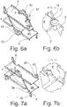
- FIG. 6a and 6b a screw connection is shown.
- the reflector plate 8 is by means of a screw 21 with a bent portion 18 (analogous to FIG. 4 ) of the web 5 connected.
- the screw 21 can also find a rivet application.
- FIGS. 7a shown to us 7b Another alternative is in the FIGS. 7a shown to us 7b. There, an edge of the reflector plate 8 is brought into contact with an edge of the web 5 and welded.
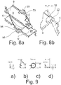
- FIGS. 8a and 8b an adhesive bond shown. Analogous to FIG. 4 a portion 18 of the web 5 is bent, so that the portion 18 extends parallel to the reflector plate 8. Between section 18 and reflector plate 8, an adhesive layer 22 is then attached.
- FIGS. 9a to 9d For example, different cross sections of the webs 5 are shown.
- FIG. 9a can the webs 5, depending on the static requirements, also a curved section ( FIG. 9b ), a round cross-section ( Figure 9c), which may also be formed of a solid metal rod, or an L-shaped cross section ( FIG. 9d ) respectively.
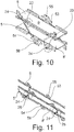
- FIG. 10 In the FIG. 10 is shown a possible wall mounting. In the region of the curved side parts 11, projections 23 are formed with an opening 24, which are used for fastening the profile.
- FIG. 11 an alternative is shown, which additionally allows the attachment of locking mechanisms.
- the openings 24 are formed in connecting portions 25 which connect the reflector plate 8 and the reflector plate 8 '.
- the connecting sections 25 can be formed integrally with the reflector plates 8 and 8 'or as a separate component, which is subsequently connected to the reflector plates 8 and 8'.
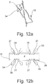
- FIG. 12a a possibility of forming a reflector plate 8 with webs 5 is shown.
- the reflector plate 8 and the webs 5 are cut out of a layer of metal and then folded.
- the side parts 11 are bent along the folding line 26 with respect to the sheet plane up or down by 90 °.
- the webs 5 are also bent either along the fold line 27 up or the fold line 28 down.
- the end portions 53 and 54 of the webs 5 are in the FIG. 12 shown purely schematically, but include mounting options for the upper and lower part, preferably in the FIG. 3 shown mounting options.
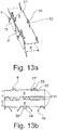
- FIG. 13a a construction with two reflector plates 8 and 8 'is shown, which is formed from a single folded sheet metal part.
- the cutout pattern is in the FIG. 13b visible.
- the sections 18 are visible, which are provided with an opening 21 '.
- the openings 21 ' come into conformity with the openings 21 "of the reflector plate 8, so that a corresponding screw connection, as in FIG. 6 , can come about.
- the sections 18 may also be configured differently, so that one of the in the FIGS. 4 to 8 shown mounting options is also conceivable.
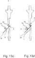
- FIGS. 13c to 13h are the bending steps for producing a reflector assembly according to FIG. 13a shown. In the the FIGS. 13c to 13h However, the order of steps shown is not binding.
- the cover fasteners 11 are also bent by 90 ° on the same side of the sheet plane as the end portions 53 and 54.
- the plane of the reflector plate 8 is bent by 90 ° with respect to the plane of the reflector plate 8 '.
- the reflector plate 8 ' is also bent by 90 °, so that the reflector plate 8 and 8' are now parallel to each other and the end portions 53 and 54 are arranged facing away from each other.
- the section 18 is then folded by 90 °, as in the Figure 13g shown.
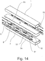
- FIG. 14 an exploded view of another embodiment of the inventive profile is shown.
- Upper part 1 and lower part 2 have openings 12, which are formed for insertion of the webs 5.
- the webs 5 are formed as a stamped part and have sections 51, which are provided with openings 52.
- the sections 51 extend parallel to the upper part 1 or lower part 2.
- the reflector plates 8 and 8 ' have at the side edges projections 81, which in terms of dimensions and spacing are matched to the openings 52 so that the projections 81 are inserted into the openings 52 for positioning and fixing the reflector plates 8 and 8 '.
- An attachment of the projections 81 is also conceivable.
- the end portions 53 and 54 of the webs 5 are preferably according to FIG. 3 connected to the upper part 1 and lower part 2.
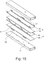
- FIG. 15 a further embodiment of the inventive profile is shown.
- the upper part 1 and the lower part 2 are also provided with openings 12 which serve for fastening the webs 5.
- the profile is formed from a sandwich arrangement.
- the reflector plate 8 or 8 ' is formed by joining both plates 82 and 83 or 84 and 85.
- the plates 82 and 83 or 84 and 85 are preferably glued or welded.
- the end portions 53 and 54 of the webs 5 are preferably according to FIG. 3 connected to the upper part 1 and lower part 2.
- FIG. 16 a further variant of the inventive profile is shown.
- the upper part 1 and the lower part 2 are also provided with openings 12 which serve for fastening the webs 5.
- the reflector plates 8 and 8 ' have openings 10, which are formed for the passage of the webs 5.
- the webs 5 are cut / punched out of a single sheet metal part and run with a zigzag pattern.
- the attachment of the webs 5 with the upper part 1 and the lower part 2 takes place as above with respect to the FIG. 3 mentioned. In this case, the attachment takes place by means of locking lugs 55 and 56th
- the inventive profile may also include a single row of webs 5, as in the FIGS. 17 and 18 shown. These embodiments are particularly preferred when the profile must be made very narrow. Depending on the embodiment, a width of 6 mm is possible, which allows a very filigree design of components.
- FIG. 17a Visible is the profile shown there formed in several parts.
- Upper part 1 and lower part 2 are connected by webs 5, which are formed like a truss.
- Upper part 1 and lower part 2 are preferably welded to the central part, which has the webs 5.
- the reflector plates 8, 8 'and 8 are integrally formed with the webs 5 and extend parallel to the upper part 1 and the lower part 2. As shown in FIG. 17b Visible protrude the reflector plates 8, 8 'and 8 "side of the webs 5 out.
- FIG. 18 is also a profile according to the invention shown with a single row of webs, which, however, is formed from a single sheet metal part.
- visible upper part 1 and lower part 2 are formed from a folded sheet metal.
- the webs 5 are formed by cutting / punching.
- the reflector surfaces 8 and 8 ' are formed by the portions 51, which extend parallel to the upper part 1 and lower part 2 and the webs 5 intersect.
Description
Die Erfindung betrifft ein Profil für Rahmen von Türen, Wandelementen oder Fenstern.The invention relates to a profile for frames of doors, wall elements or windows.
Bekannte Profile umfassen einen Oberteil und einen Unterteil, welche meistens als Hohlraumprofil ausgebildet sind. Zur thermischen Isolierung werden Oberteil und Unterteil meist mittels Isolierstegen aus einem Kunststoff miteinander verbunden. Auch ist es bekannt, um die Isoliereigenschaften des Verbundprofils zu verbessern, die Isolierstege mit Querflächen auszustatten, welche Wärmeverluste durch Konvektion und Wärmestrahlung vermindern, wie beispielsweise in der
Solche Verbundprofile eignen sich jedoch nicht für Brandschutzanwendungen, da die Kunststoff-Isolierstege bei einem Brand zum Versagen des Verbundprofils führten. Die Ausbildung von massiven Verbundprofilen aus Metall ist jedoch aus Gewichts-, Energie- und Kostengründen nicht erwünscht.However, such composite profiles are not suitable for fire protection applications, since the plastic insulating bars in a fire led to the failure of the composite profile. However, the formation of solid composite profiles of metal is not desirable for weight, energy and cost reasons.
Es ist daher Aufgabe der vorliegenden Erfindung ein Profil der eingangs genannten Art anzugeben, welche die Nachteile des Bekannten vermeidet und insbesondere eine einfache und flexible Ausbildung von einem Profil, welche an die jeweiligen Bedürfnisse anpassbar ist, für Brandschutzanwendungen geeignet ist und kostengünstig herstellbar, erlaubt.It is therefore an object of the present invention to provide a profile of the type mentioned, which avoids the disadvantages of the known and in particular a simple and flexible training of a profile which is adaptable to the particular needs, suitable for fire protection applications and inexpensive to produce allowed.
Die Aufgabe wird mit einem Profil gemäss Kennzeichen des unabhängigen Anspruchs gelöst.The object is achieved with a profile according to the characterizing part of the independent claim.
Das erfindungsgemässe Profil umfasst einen Oberteil und einen Unterteil mit je einer Aussenwand. Oberteil und Unterteil können gleich aber auch unterschiedlich ausgebildet sein. Oberteil und/oder Unterteil können beispielsweise als Hohlraumprofil ausgebildet sein. Alternativ kann das Oberteil und/oder Unterteil aus einem Vollprofil bestehen. Denkbar sind auch Verbundprofile mit einem Profilteil aus einem Metall, welches mit einer Holz-, Stein- oder Kunststoffabdeckung, welche die Aussenwand bilden, versehen ist. Als Metall für das Oberteil und/oder Unterteil und/oder Profilteil kommen beispielsweise Stahl, Edelstahl, Aluminium, Cortenstahl, Messing und Kupfer in Frage. Metalle und/oder Legierungen mit guter Korrosionsbeständigkeit und gute Wärmedämmeigenschaften können bevorzugt werden. Ferner können im Oberteil und/oder Unterteil Öffnungen zur Anbringung von Schlössern, Schaltern und dgl. und/oder zur Durchführung von Leitungen und Kabeln ausgebildet sein. Die Anbringung von Schlössern, Schaltern und dgl. und/oder Durchführung von Leitungen und Kabeln ist auch in dem zwischen Oberteil und Unterteil gebildeten Raum möglich.The inventive profile comprises an upper part and a lower part, each with an outer wall. Upper part and lower part can but also be designed differently. Upper part and / or lower part may be formed, for example, as a cavity profile. Alternatively, the upper part and / or lower part can consist of a solid profile. Also conceivable are composite profiles with a profile part made of a metal, which is provided with a wooden, stone or plastic cover which form the outer wall. As the metal for the upper part and / or lower part and / or profile part, for example, steel, stainless steel, aluminum, Cortenstahl, brass and copper come into question. Metals and / or alloys with good corrosion resistance and good thermal insulation properties may be preferred. Furthermore, in the upper part and / or lower part openings for attaching locks, switches and the like. And / or for the implementation of cables and cables may be formed. The attachment of locks, switches and the like. And / or implementation of cables and cables is also possible in the space formed between the upper part and lower part.
Oberteil und Unterteil sind miteinander durch Stege aus Metall verbunden. Die Stege können derart ausgebildet sein, dass eine Entfernung vom Oberteil bzw. Unterteil jederzeit möglich ist.Upper part and lower part are connected to each other by webs of metal. The webs may be designed such that a distance from the upper part or lower part is possible at any time.
Bevorzugt sind Oberteil und Unterteil über die gesamten Länge des Profils gleich beabstandet.Preferably, upper part and lower part are equally spaced over the entire length of the profile.
Erfindungsgemäss ist wenigstens eine Reflektorplatte zwischen Oberteil und Unterteil angeordnet.According to the invention, at least one reflector plate is arranged between upper part and lower part.
Die wenigstens eine Reflektorplatte erstreckt sich bevorzugt sich im Wesentlichen über die gesamte Breite des Profils. Bevorzugt erstreckt sich die wenigstens eine Reflektorplatte auch über die gesamte Länge des Profils.The at least one reflector plate preferably extends substantially over the entire width of the profile. Preferably, the at least one reflector plate also extends over the entire length of the profile.
Je nach Breite des Profils und Dicke der Steganordnung kann die Wirkung der Reflektorplatte bereits durch die Fläche der Stege erreicht werden, die parallel zum Oberteil bzw. Unterteil ausgebildet sind. Bevorzugt umfassen die Stege in einem solchen Fall zusätzlich Abschnitte, welche parallel zum Oberteil und/oder Unterteil verlaufen und als Reflektorfläche dienen.Depending on the width of the profile and thickness of the web arrangement, the effect of the reflector plate can already be achieved by the surface of the webs, which are formed parallel to the upper part or lower part. In such a case, the webs preferably additionally comprise sections which run parallel to the upper part and / or lower part and serve as a reflector surface.
Die Längsachse des Ober- bzw. Unterteils entspricht dabei einer Längserstreckungsrichtung des Ober- bzw. Unterteils, welche meistens auch als Länge bezeichnet wird und die grösste Abmessung des Ober- und Unterteils darstellt. Die Breite des Profils erstreckt sich gemäss der Erfindung senkrecht zur Länge in der Ebene der Aussenwand.The longitudinal axis of the upper or lower part corresponds to a longitudinal direction of the upper or lower part, which is usually also referred to as length and represents the largest dimension of the upper and lower parts. The width of the profile extends according to the invention perpendicular to the length in the plane of the outer wall.
Es hat sich gezeigt, dass für eine gute thermische Isolierung die Reflektorplatte sich im Wesentlichen über die gesamte Breite des Profils zu erstrecken und die Verbindung zwischen Oberteil und Unterteil über Stege und nicht über eine durchgehende Wand zu erfolgen hat. Die Stege sind aus Gewichts- und Wärmeleitgründen (Herabsetzung des Lambda-Wertes) zu bevorzugen.It has been found that for a good thermal insulation, the reflector plate to extend substantially over the entire width of the profile and the connection between the upper part and lower part via webs and not to have a continuous wall. The webs are for weight and Wärmeleitgründen (reduction of the lambda value) to be preferred.
Bevorzugt befinden sich die Stege, bezüglich der Längsachse des Oberteils und Unterteils, jeweils in einem ersten und zweiten Seitenbereich des Ober- bzw. Unterteils. Dabei erstreckt sich die wenigstens eine Reflektorplatte von den Stegen des ersten Seitenbereichs zu den Stegen des zweiten Seitenbereichs. Es hat sich gezeigt, dass es für eine gute thermische Isolierung nicht notwendig ist, dass die Seitenbereiche des Profils komplett geschlossen sind. Es genügt dass die Reflektorplatte sich im Wesentlichen über die gesamte Breite des Profils erstreckt. Somit können in den Seitenbereichen lediglich Stege angeordnet werden, welche aus Gewichts- und Wärmeleitgründen zu bevorzugen sind. Die Reflektorplatte versteift auch das Profil, so dass die Stege entsprechend schmal und leicht ausgebildet werden können.Preferably, the webs, with respect to the longitudinal axis of the upper part and lower part, respectively in a first and second side region of the upper or lower part. In this case, the at least one reflector plate extends from the webs of the first side region to the webs of the second side region. It has been shown that it is not necessary for a good thermal insulation, that the side portions of the profile are completely closed. It is sufficient that the reflector plate extends substantially over the entire width of the profile. Thus, only webs can be arranged in the side regions, which for weight and Wärmeleitgründen to prefer are. The reflector plate also stiffens the profile, so that the webs can be made correspondingly narrow and lightweight.
Durch geeignete Auslegung der Anordnung von Oberteil, Unterteil und Reflektorplatte(n), insbesondere der Dicke der Reflektorplatte(n) und deren Abstand, kann ferner eine beschusshemmende Wirkung erreicht werden. Zum Erreichen einer höheren Durschusshemmungsklasse können zusätzliche Materialien zur Anwendung kommen. Beispielsweise können zusätzliche Panzerungen aus einem Metall und/oder Kunstfasern (z.B. Aramide) im Oberteil und/oder Unterteil und/oder in dem zwischen Oberteil und Unterteil gebildeten Raum angeordnet werden. Oberteil und/oder Unterteil können zudem oder alternativ als Vollprofil gefertigt werden.By suitable design of the arrangement of upper part, lower part and reflector plate (s), in particular the thickness of the reflector plate (s) and their distance, a bullet-resistant effect can also be achieved. To achieve a higher shot-stop class, additional materials may be used. For example, additional armor made of a metal and / or synthetic fibers (e.g., aramid) may be placed in the top and / or bottom and / or in the space formed between top and bottom. Upper part and / or lower part can also or alternatively be manufactured as a solid profile.
Die Stege des jeweiligen Seitenbereichs sind bevorzugt aneinandergereiht, so dass jeweils in dem ersten und zweiten Seitenbereich die Stege in Längsrichtung fluchtend angeordnet sind.The webs of the respective side region are preferably strung together, so that in each case in the first and second side region, the webs are arranged in alignment in the longitudinal direction.
Alternativ kann das Profil aneinandergereihte Stege aufweisen, welche Oberteil und Unterteil miteinander verbinden. In diesem Fall ist nur eine einzige Reihe von Stegen vorhanden, welche bevorzugt mittig des Oberteils und/oder Unterteils angeordnet ist. Eine solche Ausführung ist besonders für in der Breite sehr schmal ausgebildete Profile vorteilhaft.Alternatively, the profile may have juxtaposed webs which connect the upper part and lower part with each other. In this case, only a single row of webs is present, which is preferably arranged centrally of the upper part and / or lower part. Such a design is particularly advantageous for very narrow in width profiles formed.
Die wenigstens eine Reflektorplatte weist bevorzugt eine oder zwei im Wesentlichen ebene Reflektorflächen auf.The at least one reflector plate preferably has one or two substantially flat reflector surfaces.
Eine im Wesentlichen ebene Reflektorfläche ist in der Fertigung einfach und zudem für die Rückstrahlungseigenschaften der Reflektorfläche bestens geeignet.A substantially flat reflector surface is simple in production and also best suited for the reflective properties of the reflector surface.
Bevorzugt umfasst das Profil mehrere Reflektorplatten mit parallel zueinander angeordneten Reflektorflächen.Preferably, the profile comprises a plurality of reflector plates with reflector surfaces arranged parallel to one another.
Durch die mehrfache Anordnung von Reflektorplatten können die Isoliereigenschaften und die Brandbeständigkeit verbessert werden.The multiple arrangement of reflector plates, the insulating properties and fire resistance can be improved.
Bevorzugt ist zumindest eine Reflektorfläche mit einer infrarotstrahlung-reflektiven Beschichtung versehen. Besonders bevorzugt sind auch die der Reflektorfläche(n) zugewandten Innenflächen des Oberteils und/oder Unterteils ebenfalls mit einer solchen Beschichtung versehen.At least one reflector surface is preferably provided with an infrared-radiation-reflective coating. Particularly preferably, the inner surfaces of the upper part and / or lower part facing the reflector surface (s) are also provided with such a coating.
Damit werden die Rückstrahlungseigenschaften der Reflektorplatte noch weiter verbessert.Thus, the return properties of the reflector plate are further improved.
Die wenigstens eine Reflektorfläche ist insbesondere parallel zur Aussenwand des Oberteils und Unterteils angeordnet. Weiter bevorzugt sind sowohl Oberteil als auch Unterteil derart ausgebildet, dass eine der Reflektorplatte zugewandte Innenwand ebenfalls parallel zur Reflektorfläche angeordnet ist.The at least one reflector surface is arranged in particular parallel to the outer wall of the upper part and lower part. More preferably, both upper part and lower part are formed such that one of the reflector plate facing inner wall is also arranged parallel to the reflector surface.
Dadurch werden die Isoliereigenschaften noch weiter verbessert.As a result, the insulating properties are further improved.
Die Reflektorplatte ist bevorzugt aus Metall.The reflector plate is preferably made of metal.
Insbesondere wenn die Reflektorplatte nicht mit einer infrarotstrahlung-reflektiven Beschichtung versehen ist, sind Reflektorplatten mit einer polierten Oberfläche besonders bevorzugt, da diese die Rückstrahlungseigenschaften der Reflektorplatte positiv beeinflussen.In particular, if the reflector plate is not provided with an infrared radiation-reflective coating, reflector plates with a polished surface are particularly preferred because they positively affect the return properties of the reflector plate.
Bevorzugt sind die Stege zur Bildung einer Fachwerkanordnung schräg angeordnet.Preferably, the webs are arranged obliquely to form a truss arrangement.
Im Rahmen der Erfindung bedeutet schräg einen Winkel von 1° bis 89° zur Längsachse, bzw. 91° bis 179°.In the context of the invention obliquely means an angle of 1 ° to 89 ° to the longitudinal axis, or 91 ° to 179 °.
Eine Fachwerkanordnung ist besonders für die Schubfestigkeit des Profils bevorzugt. Zudem können die Stege aus einem einzigen Metallblatt ausgeschnitten oder ausgestanzt werden zur Bildung eines Zickzackprofils.A framework arrangement is particularly preferred for the shear strength of the profile. In addition, the webs can be cut or punched from a single metal sheet to form a zigzag profile.
Die Stege können aber auch senkrecht zur Aussenwand des Oberteils und/oder Unterteils angeordnet werden.However, the webs can also be arranged perpendicular to the outer wall of the upper part and / or lower part.
Bevorzugt weist die wenigstens eine Reflektorplatte Öffnungen auf, in welche die Stege einschiebbar sind.Preferably, the at least one reflector plate openings, in which the webs are inserted.
Diese Ausführungsform stellt eine einfache Möglichkeit der Befestigung der Reflektorplatte dar. Die Reflektorplatte kann einfach auf die Stege aufgesteckt werden.This embodiment provides a simple way of attaching the reflector plate. The reflector plate can be easily attached to the webs.
Zusätzlich oder alternativ kann die Reflektorplatte mit weiteren Mitteln versehen sein, welche zur Befestigung an den Stegen dienen. Denkbar ist eine Steckverbindung mit Rastelementen am Steg bzw. an der Reflektorplatte, welche in entsprechende Öffnungen der Reflektorplatte bzw. des Steges greifen. Eine Klemmverbindung durch Falzen ist ebenso denkbar wie eine Schraub- oder Nietenverbindung, eine Schweissverbindung und/oder eine Klebverbindung.Additionally or alternatively, the reflector plate may be provided with further means, which serve for attachment to the webs. It is conceivable a connector with locking elements on the web or on the reflector plate, which engage in corresponding openings of the reflector plate or the web. A clamping connection by folding is also conceivable as a screw or rivet connection, a welded connection and / or an adhesive bond.
Eine andere Ausführungsform der Erfindung sieht vor, dass die Stege aus wenigstens zwei Segmenten ausgebildet sind und die wenigstens eine Reflektorplatte als Verbindungsstück für die beiden Segmente ausgebildet ist.Another embodiment of the invention provides that the webs are formed of at least two segments and at least a reflector plate is formed as a connecting piece for the two segments.
Bevorzugt sind die Stege in einem Endbereich mit Befestigungsmitteln zur Befestigung an dem Oberteil bzw. Unterteil versehen.Preferably, the webs are provided in an end region with fastening means for attachment to the upper part or lower part.
Die Befestigungsmittel können als Rastelement ausgebildet sein, welche in entsprechende Öffnungen oder Nuten des Ober- bzw. Unterteils eingesteckt werden. Umgekehrt können die Stege mit Öffnungen versehen sein, welche beim Einstecken in das Ober- bzw. Unterteil mir Rastmitteln zusammenwirken. Alternativ kann die Verbindung durch Klemmen, Falzen oder Rollen von Abschnitten des Steges mit dem Ober- bzw. Unterteil erfolgen. Weitere Möglichkeiten sind eine Schraub- und/oder Nietenverbindung und/oder eine Schweissverbindung und/oder eine Klebverbindung.The fastening means may be formed as a latching element, which are inserted into corresponding openings or grooves of the upper or lower part. Conversely, the webs can be provided with openings which cooperate with the insertion into the upper or lower part of me locking means. Alternatively, the connection can be made by clamping, folding or rolling sections of the web with the upper or lower part. Further possibilities are a screw and / or rivet connection and / or a welded connection and / or an adhesive connection.
Bevorzugt ist die wenigstens eine Reflektorplatte mit den Stegen und/oder Stegsegmenten einstückig ausgebildet.Preferably, the at least one reflector plate is integrally formed with the webs and / or web segments.
Eine solche Ausgestaltung erlaubt eine einfache Fertigung der Stege und der Reflektorplatte. Bevorzugt sind die Stege und/oder Stegsegmente und die wenigstens eine Reflektorplatte aus einem einzigen Blechteil ausgestanzt oder ausgeschnitten und werden anschliessend gefaltet zur Bildung der dreidimensionalen Struktur.Such a configuration allows easy production of the webs and the reflector plate. Preferably, the webs and / or web segments and the at least one reflector plate are punched or cut out of a single sheet metal part and are then folded to form the three-dimensional structure.
Zur Erhöhung der Brandschutzeigenschaften kann das Profil ferner ein intumeszentes Material und/oder ein beim Brand Wasser freigebendes Material (z.B. Wasserglas) und/oder ein wärmedämmendes Material umfassen , welches zwischen dem Oberteil und dem Unterteil und/oder lediglich in dem Oberteil bzw. Unterteil angeordnet ist. Das intumeszente Material und/oder das beim Brand Wasser freigebende Material (z.B. Wasserglas) und/oder das wärmedämmende Material kann beispielsweise nur zwischen dem Oberteil und der Reflektorplatte oder nur zwischen zwei Reflektorplatten angeordnet sein.To increase the fire protection properties, the profile may further comprise an intumescent material and / or a water-releasing material (eg, water glass) and / or a heat-insulating material disposed between the top and the bottom and / or only in the top or bottom is. The intumescent material and / or the fire-releasing material (eg water glass) and / or the heat-insulating Material may for example be arranged only between the upper part and the reflector plate or only between two reflector plates.
Bevorzugt ist die wenigstens eine Reflektorplatte mit Mitteln zur Befestigung einer Abdeckung versehen.Preferably, the at least one reflector plate is provided with means for fixing a cover.
Die Mittel zur Befestigung einer Abdeckung sind bevorzugt als Rastelement ausgebildet. Andere Möglichkeiten wie Klemm-, Schraub-, Niet- und Klebverbindungen sind ebenso denkbar.The means for fixing a cover are preferably formed as a latching element. Other options such as clamping, screw, rivet and adhesive joints are also conceivable.
Das Profil und insbesondere die Reflektorplatten und/oder die Stege weisen bevorzugt Mittel zur Befestigung, beispielsweise an einer Wand oder für die Befestigung von Schlössern und dgl., auf. Diese Mittel sind bevorzugt als Öffnung für eine Schraube oder Bolzen/Stift ausgebildet. Vorteilhaft bei einer Anordnung der Mittel zur Befestigung an den Stegen ist, dass thermische Brücken weitestgehend vermieden werden.The profile and in particular the reflector plates and / or the webs preferably have means for attachment, for example on a wall or for the attachment of locks and the like., On. These means are preferably designed as an opening for a screw or bolt / pin. An advantage of an arrangement of the means for attachment to the webs is that thermal bridges are largely avoided.
Die Erfindung wird nachfolgend anhand von Ausführungsbeispielen in Verbindung mit der Zeichnung besser erläutert. Es zeigen:
- Fig. 1
- eine perspektivische Ansicht einer besonderen Ausführungsform eines erfindungsgemässen Profils;
- Fig. 2a
- eine schematische Schnittansicht durch einen Oberteil bzw. Unterteil;
- Fig. 2b
- eine schematische Schnittansicht durch einen Oberteil bzw. Unterteil;
- Fig. 3a-e
- verschiedene Möglichkeiten der Befestigung zwischen Steg und Ober- bzw. Unterteil;
- Fig. 4a
- eine perspektivische Ansicht einer gesteckten Reflektorplatte;
- Fig. 4b
- eine Detailansicht der Steckverbindung der
Figur 4a ; - Fig. 5a
- eine perspektivische Ansicht einer geklemmten Reflektorplatte;
- Fig. 5b
- eine Detailansicht der Klemmverbindung der
Figur 5a ; - Fig. 6a
- eine perspektivische Ansicht einer geschraubten Reflektorplatte;
- Fig. 6b
- eine Detailansicht der Schraubverbindung der
Figur 6a ; - Fig. 7a
- eine perspektivische Ansicht einer geschweissten Reflektorplatte;
- Fig. 7b
- eine Detailansicht der Schweissverbindung der
Figur 7a ; - Fig. 8a
- eine perspektivische Ansicht einer geklebten Reflektorplatte;
- Fig. 8b
- eine Detailansicht der Klebverbindung der
Figur 8a ; - Fig. 9a-d
- mögliche Querschnitte der Stege;
- Fig. 10
- ein Profil mit Befestigungsöffnungen für eine Wand;
- Fig. 11
- ein Profil mit Befestigungsmöglichkeiten für ein Schloss;
- Fig. 12a
- eine perspektivische Ansicht einer einstückig mit den Stegen ausgebildete Reflektorplatte;
- Fig. 12b
- die Reflektorplatte der
Fig. 12a vor dem Falten; - Fig. 13a
- eine perspektivische Ansicht einer einstückig mit den Stegen ausgebildete, zweifache Reflektorplatte,
- Fig. 13b
- die zweifache Reflektorplatte der
Fig. 13a vor dem Falten; - Fig. 13c-h
- die Herstellungsschritte der Reflektoranordnung gemäss
Figur 13a ; - Fig. 14
- eine bevorzugte Ausführungsformmit seitlich eingesteckten Reflektorplatten;
- Fig. 15
- eine bevorzugte Ausführungsform mit geklebten Reflektorplatten;
- Fig. 16
- eine bevorzugte Ausführungsform mit auf die Stege aufgesteckten Reflektorplatten;
- Fig. 17a
- eine Explosionsdarstellung einer bevorzugten Ausführungsform mit einer einzigen Stegreihe
- Fig. 17b
- eine Schnittansicht der Ausführungsform der
Figur 17a ; - Fig. 18a
- eine perspektivische Ansicht einer weiteren bevorzugten Ausführungsform mit einer einzigen Stegreihe; und
- Fig. 18b
- eine Schnittansicht durch das Profil der
Figur 18a
- Fig. 1
- a perspective view of a particular embodiment of a novel profile;
- Fig. 2a
- a schematic sectional view through an upper part or lower part;
- Fig. 2b
- a schematic sectional view through an upper part or lower part;
- Fig. 3a-e
- various possibilities of attachment between web and upper or lower part;
- Fig. 4a
- a perspective view of a plugged reflector plate;
- Fig. 4b
- a detailed view of the connector of
FIG. 4a ; - Fig. 5a
- a perspective view of a clamped reflector plate;
- Fig. 5b
- a detailed view of the clamping connection of
FIG. 5a ; - Fig. 6a
- a perspective view of a screwed reflector plate;
- Fig. 6b
- a detailed view of the screw of the
FIG. 6a ; - Fig. 7a
- a perspective view of a welded reflector plate;
- Fig. 7b
- a detailed view of the welded joint of
Figure 7a ; - Fig. 8a
- a perspective view of a glued reflector plate;
- Fig. 8b
- a detailed view of the adhesive bond of
FIG. 8a ; - Fig. 9a-d
- possible cross sections of the webs;
- Fig. 10
- a profile with mounting holes for a wall;
- Fig. 11
- a profile with mounting options for a lock;
- Fig. 12a
- a perspective view of an integrally formed with the webs reflector plate;
- Fig. 12b
- the reflector plate the
Fig. 12a before folding; - Fig. 13a
- a perspective view of an integrally formed with the webs, two-fold reflector plate,
- Fig. 13b
- the double reflector plate of
Fig. 13a before folding; - Fig. 13c-h
- the manufacturing steps of the reflector assembly according to
FIG. 13a ; - Fig. 14
- a preferred embodiment with laterally inserted reflector plates;
- Fig. 15
- a preferred embodiment with glued reflector plates;
- Fig. 16
- a preferred embodiment with plugged on the webs reflector plates;
- Fig. 17a
- an exploded view of a preferred embodiment with a single row of webs
- Fig. 17b
- a sectional view of the embodiment of the
Figure 17a ; - Fig. 18a
- a perspective view of another preferred embodiment with a single row of webs; and
- Fig. 18b
- a sectional view through the profile of
FIG. 18a
Der in der
Das Oberteil 1 und das Unterteil 1 sind von schräg und fachwerkartig angeordneten Stegen 5 aus Metall miteinander verbunden. Zwischen Oberteil 1 und Unterteil 2, parallel zu den Aussenwänden 3 und 4 sind Reflektorplatten 8 und 8' aus einem Metall angeordnet, welche sich über die gesamte Länge und Breite des Profils erstrecken. Die jeweils dem benachbarten Oberteil 1 bzw. Unterteil 2 zugewandte Fläche wird als Reflektorfläche 9 bzw. 9' bezeichnet und ist eben und poliert. Die übrige, der jeweils anderen Reflektorplatte zugewandte Fläche wird als Reflektorfläche 99 und 99' bezeichnet und ist ebenfalls eben und poliert.The
Wie aus der
Die Reflektorplatte 8 bzw. 8' weist gebogene Seitenteile 11 auf, welche als Befestigungsmittel für eine hier nicht dargestellte Seitenabdeckung dienen.The
Die
Das Oberteil 1 der
Das Oberteil 1 der
Die Befestigung der Stege 5 ist in der
Gemäss
Die Verbindung kann auch gemäss
Möglich ist auch eine Verbindung mittels einer Schraube oder eines Stiftes/Bolzens (schematisch durch die Linie 55 gezeigt), wie in der
Gemäss
Aus der
Entsprechend gilt für die Verbindung mit einem Unterteil 2 in einem Endbereich 54 des Stegs 5.Accordingly applies to the connection with a
In den
Die in der
In den
In den
In den
Eine weitere Alternative ist in den
Schliesslich ist in den
In der
In der
In der
In der
In der
Zu vermerken ist, dass die Endabschnitte 53 und 54 mit einer Rastnase 55 und 56, wie in der
Ferner sind die Abschnitte 18 sichtbar, welche mit einer Öffnung 21' versehen sind. Beim Zusammenfalten der Konstruktion kommen die Öffnungen 21' in Übereinstimmung mit den Öffnungen 21" der Reflektorplatte 8, so dass eine entsprechende Schraubverbindung, wie in der
In den
Zunächst werden gemäss
Danach werden, wie in der
Gemäss
Im nachfolgenden Schritt der
Der Abschnitt 18 wird dann um 90° abgekantet, wie in der
Anschliessend wird gemäss
In der
In der
In der
Das erfindungsgemässe Profil kann auch eine einzige Reihe von Stegen 5 umfassen, wie in den
Wie in der
In der
Claims (15)
- Profile for frames of doors, wall elements or windows, comprising an upper part (1) and a lower part (2), each with an outer wall (3, 4), and metal crosspieces (5), which connect the upper part (1) and the lower part (2),
characterized in that
at least one metal reflector plate (8) is arranged between the upper part (1) and lower part (2). - Profile according to Claim 1, characterized in that the at least one reflector plate (8) extends essentially over the entire width of the profile, preferably also over the entire length of the profile.
- Profile according to Claim 1 or 2, characterized in that the crosspieces (5) are each arranged, preferably in a state in which they are lined up in a row in a first and second side region (6, 7), as seen in relation to a longitudinal axis of the upper part (1) and lower part (2), wherein the at least one reflector plate (8) extends from the crosspieces (5) of the first side region (6) to the crosspieces (5) of the second side region (7).
- Profile according to Claim 1 or 2, characterized in that the crosspieces are arranged in a state in which they are lined up in a row, preferably in the centre of the upper part (1) and lower part (2), as seen in relation to a longitudinal axis of the upper part (1) and lower part (2).
- Profile according to one of the preceding claims, characterized in that the at least one reflector plate (8) has one or two essentially planar reflector surfaces (9, 99).
- Profile according to one of the preceding claims, characterized in that the profile has a plurality of reflector plates (8, 8') with reflector surfaces (9, 99; 9', 99') arranged parallel to one another.
- Profile according to one of the preceding claims, characterized in that the at least one reflector surface (9, 99; 9', 99') has a coating which reflects infra-red radiation.
- Profile according to one of the preceding claims, characterized in that the at least one reflector surface 9, 99; 9', 99') is arranged parallel to the outer wall (3, 4).
- Profile according to one of the preceding claims, characterized in that the crosspieces (5) are arranged obliquely in order to form a framework arrangement.
- Profile according to one of the preceding claims, characterized in that the crosspieces (5) are provided, in an end region (53, 54), with fastening means (55, 56) for fastening on the upper part (1) and lower part (2), respectively.
- Profile according to one of the preceding claims, characterized in that the at least one reflector plate (8) is formed in one piece with the crosspieces (5) and/or crosspiece segments.
- Profile according to one of the preceding claims, characterized in that the profile also comprises an intumescent material and/or a material which releases water in the event of fire and/or a heat-insulating material, said material being arranged between the upper part (1) and the lower part (2).
- Profile according to one of the preceding claims, characterized in that the at least one reflector plate (8) is provided with means (11) for fastening a covering.
- Profile according to one of the preceding claims, characterized in that the upper part (1) and/or the lower part (2) are/is designed in the form of a cavity profile and/or solid profile and/or composite profile.
- Profile according to one of the preceding claims, characterized in that at least one reflector plate (8) and the crosspieces (5) are formed from a single, folded metal sheet.
Priority Applications (2)
| Application Number | Priority Date | Filing Date | Title |
|---|---|---|---|
| EP16163879.6A EP3228794B1 (en) | 2016-04-05 | 2016-04-05 | Profile for frames of doors, wall elements or windows |
| PL16163879T PL3228794T3 (en) | 2016-04-05 | 2016-04-05 | Profile for frames of doors, wall elements or windows |
Applications Claiming Priority (1)
| Application Number | Priority Date | Filing Date | Title |
|---|---|---|---|
| EP16163879.6A EP3228794B1 (en) | 2016-04-05 | 2016-04-05 | Profile for frames of doors, wall elements or windows |
Publications (2)
| Publication Number | Publication Date |
|---|---|
| EP3228794A1 EP3228794A1 (en) | 2017-10-11 |
| EP3228794B1 true EP3228794B1 (en) | 2019-05-08 |
Family
ID=55661335
Family Applications (1)
| Application Number | Title | Priority Date | Filing Date |
|---|---|---|---|
| EP16163879.6A Active EP3228794B1 (en) | 2016-04-05 | 2016-04-05 | Profile for frames of doors, wall elements or windows |
Country Status (2)
| Country | Link |
|---|---|
| EP (1) | EP3228794B1 (en) |
| PL (1) | PL3228794T3 (en) |
Family Cites Families (4)
| Publication number | Priority date | Publication date | Assignee | Title |
|---|---|---|---|---|
| DE4443762A1 (en) * | 1994-12-08 | 1996-06-13 | Schueco Int Kg | Framework made of metal profiles in fire protection for windows, doors, facades or glass roofs |
| DE29520444U1 (en) | 1995-12-22 | 1996-03-21 | Lange Rolf Peter | Insulating webs to improve thermal insulation |
| EP1510643B1 (en) * | 2003-09-01 | 2017-12-13 | Forster Profilsysteme AG | Profile and method of its manufacture |
| DE202007016649U1 (en) | 2007-04-02 | 2008-04-30 | Technoform Caprano Und Brunnhofer Gmbh & Co. Kg | Ladder-shaped insulating bar for a composite profile for window, door and facade elements and composite profile for window, door and facade elements |
-
2016
- 2016-04-05 PL PL16163879T patent/PL3228794T3/en unknown
- 2016-04-05 EP EP16163879.6A patent/EP3228794B1/en active Active
Non-Patent Citations (1)
| Title |
|---|
| None * |
Also Published As
| Publication number | Publication date |
|---|---|
| PL3228794T3 (en) | 2019-10-31 |
| EP3228794A1 (en) | 2017-10-11 |
Similar Documents
| Publication | Publication Date | Title |
|---|---|---|
| DE1812241C3 (en) | Curtain wall with a support frame made of posts and bars | |
| EP2476853B1 (en) | Connecting section for windows, doors and façades as well as method for producing the same | |
| EP1980701B1 (en) | Heat-insulated composite profile, in particular for windows, doors, facades and such | |
| EP0100824B1 (en) | Compound profile, in particular for frames of windows, doors and front elements | |
| EP3914799B1 (en) | Profile system | |
| EP1988229B1 (en) | Panel for constructing a wall or a ceiling of a construct and construction component made from such panels | |
| EP2003280B1 (en) | Door leaf, ideally for a front door of a house | |
| DE102008034055B4 (en) | security Zone | |
| EP1840314B1 (en) | Fire resistant construction element | |
| EP3228794B1 (en) | Profile for frames of doors, wall elements or windows | |
| DE102004038868A1 (en) | Thermally insulated profile for windows, doors, facade elements and the like comprises thermal insulating elements which are located between profile elements, and are made of two materials with different strengths | |
| EP1728934B1 (en) | Profile for frames of windows, wall elements or doors | |
| EP2781866B2 (en) | Wall panel for a drying plant and method for producing the wall panel | |
| DE10110795A1 (en) | Surround profile firestop endfaces have edges joined by web pieces between slots either side in rows parallel to the profile using firestop strips held in center part groove. | |
| EP2105063A1 (en) | Furniture body | |
| EP1944451B1 (en) | Frame for fire-resistant doors with several parallel profile parts | |
| EP1681430A2 (en) | Composite profile for frames of wall elements, doors and windows | |
| EP1182317B1 (en) | Thermally insulating profile member for fire-proof constructions | |
| EP3450649B1 (en) | Fastening profile | |
| AT402836B (en) | HOLDING DEVICE FOR PANELS, ESPECIALLY GLASS PANELS, IN CUT-OUTS OF COMPONENTS | |
| DE19511081A1 (en) | Window or door profile assembly | |
| DE4227531C2 (en) | Corner connector for a frame of a control cabinet | |
| DE202010013228U1 (en) | Support arrangement for a window, a door or the like. | |
| DE10203276C2 (en) | Lightweight structural element with locking tongue and groove effect | |
| DE10207482A1 (en) | door segment |
Legal Events
| Date | Code | Title | Description |
|---|---|---|---|
| PUAI | Public reference made under article 153(3) epc to a published international application that has entered the european phase |
Free format text: ORIGINAL CODE: 0009012 |
|
| STAA | Information on the status of an ep patent application or granted ep patent |
Free format text: STATUS: THE APPLICATION HAS BEEN PUBLISHED |
|
| AK | Designated contracting states |
Kind code of ref document: A1 Designated state(s): AL AT BE BG CH CY CZ DE DK EE ES FI FR GB GR HR HU IE IS IT LI LT LU LV MC MK MT NL NO PL PT RO RS SE SI SK SM TR |
|
| AX | Request for extension of the european patent |
Extension state: BA ME |
|
| STAA | Information on the status of an ep patent application or granted ep patent |
Free format text: STATUS: REQUEST FOR EXAMINATION WAS MADE |
|
| 17P | Request for examination filed |
Effective date: 20180314 |
|
| RBV | Designated contracting states (corrected) |
Designated state(s): AL AT BE BG CH CY CZ DE DK EE ES FI FR GB GR HR HU IE IS IT LI LT LU LV MC MK MT NL NO PL PT RO RS SE SI SK SM TR |
|
| GRAP | Despatch of communication of intention to grant a patent |
Free format text: ORIGINAL CODE: EPIDOSNIGR1 |
|
| STAA | Information on the status of an ep patent application or granted ep patent |
Free format text: STATUS: GRANT OF PATENT IS INTENDED |
|
| INTG | Intention to grant announced |
Effective date: 20181123 |
|
| GRAS | Grant fee paid |
Free format text: ORIGINAL CODE: EPIDOSNIGR3 |
|
| GRAA | (expected) grant |
Free format text: ORIGINAL CODE: 0009210 |
|
| STAA | Information on the status of an ep patent application or granted ep patent |
Free format text: STATUS: THE PATENT HAS BEEN GRANTED |
|
| AK | Designated contracting states |
Kind code of ref document: B1 Designated state(s): AL AT BE BG CH CY CZ DE DK EE ES FI FR GB GR HR HU IE IS IT LI LT LU LV MC MK MT NL NO PL PT RO RS SE SI SK SM TR |
|
| REG | Reference to a national code |
Ref country code: GB Ref legal event code: FG4D Free format text: NOT ENGLISH |
|
| REG | Reference to a national code |
Ref country code: CH Ref legal event code: EP Ref country code: AT Ref legal event code: REF Ref document number: 1130380 Country of ref document: AT Kind code of ref document: T Effective date: 20190515 |
|
| REG | Reference to a national code |
Ref country code: DE Ref legal event code: R096 Ref document number: 502016004515 Country of ref document: DE Ref country code: IE Ref legal event code: FG4D Free format text: LANGUAGE OF EP DOCUMENT: GERMAN |
|
| REG | Reference to a national code |
Ref country code: CH Ref legal event code: NV Representative=s name: ORITI PATENTS - FRANCO ORITI, CH |
|
| REG | Reference to a national code |
Ref country code: NL Ref legal event code: FP |
|
| REG | Reference to a national code |
Ref country code: LT Ref legal event code: MG4D |
|
| PG25 | Lapsed in a contracting state [announced via postgrant information from national office to epo] |
Ref country code: NO Free format text: LAPSE BECAUSE OF FAILURE TO SUBMIT A TRANSLATION OF THE DESCRIPTION OR TO PAY THE FEE WITHIN THE PRESCRIBED TIME-LIMIT Effective date: 20190808 Ref country code: PT Free format text: LAPSE BECAUSE OF FAILURE TO SUBMIT A TRANSLATION OF THE DESCRIPTION OR TO PAY THE FEE WITHIN THE PRESCRIBED TIME-LIMIT Effective date: 20190908 Ref country code: FI Free format text: LAPSE BECAUSE OF FAILURE TO SUBMIT A TRANSLATION OF THE DESCRIPTION OR TO PAY THE FEE WITHIN THE PRESCRIBED TIME-LIMIT Effective date: 20190508 Ref country code: AL Free format text: LAPSE BECAUSE OF FAILURE TO SUBMIT A TRANSLATION OF THE DESCRIPTION OR TO PAY THE FEE WITHIN THE PRESCRIBED TIME-LIMIT Effective date: 20190508 Ref country code: HR Free format text: LAPSE BECAUSE OF FAILURE TO SUBMIT A TRANSLATION OF THE DESCRIPTION OR TO PAY THE FEE WITHIN THE PRESCRIBED TIME-LIMIT Effective date: 20190508 Ref country code: SE Free format text: LAPSE BECAUSE OF FAILURE TO SUBMIT A TRANSLATION OF THE DESCRIPTION OR TO PAY THE FEE WITHIN THE PRESCRIBED TIME-LIMIT Effective date: 20190508 Ref country code: ES Free format text: LAPSE BECAUSE OF FAILURE TO SUBMIT A TRANSLATION OF THE DESCRIPTION OR TO PAY THE FEE WITHIN THE PRESCRIBED TIME-LIMIT Effective date: 20190508 Ref country code: LT Free format text: LAPSE BECAUSE OF FAILURE TO SUBMIT A TRANSLATION OF THE DESCRIPTION OR TO PAY THE FEE WITHIN THE PRESCRIBED TIME-LIMIT Effective date: 20190508 |
|
| PG25 | Lapsed in a contracting state [announced via postgrant information from national office to epo] |
Ref country code: RS Free format text: LAPSE BECAUSE OF FAILURE TO SUBMIT A TRANSLATION OF THE DESCRIPTION OR TO PAY THE FEE WITHIN THE PRESCRIBED TIME-LIMIT Effective date: 20190508 Ref country code: GR Free format text: LAPSE BECAUSE OF FAILURE TO SUBMIT A TRANSLATION OF THE DESCRIPTION OR TO PAY THE FEE WITHIN THE PRESCRIBED TIME-LIMIT Effective date: 20190809 Ref country code: BG Free format text: LAPSE BECAUSE OF FAILURE TO SUBMIT A TRANSLATION OF THE DESCRIPTION OR TO PAY THE FEE WITHIN THE PRESCRIBED TIME-LIMIT Effective date: 20190808 Ref country code: LV Free format text: LAPSE BECAUSE OF FAILURE TO SUBMIT A TRANSLATION OF THE DESCRIPTION OR TO PAY THE FEE WITHIN THE PRESCRIBED TIME-LIMIT Effective date: 20190508 |
|
| PG25 | Lapsed in a contracting state [announced via postgrant information from national office to epo] |
Ref country code: CZ Free format text: LAPSE BECAUSE OF FAILURE TO SUBMIT A TRANSLATION OF THE DESCRIPTION OR TO PAY THE FEE WITHIN THE PRESCRIBED TIME-LIMIT Effective date: 20190508 Ref country code: RO Free format text: LAPSE BECAUSE OF FAILURE TO SUBMIT A TRANSLATION OF THE DESCRIPTION OR TO PAY THE FEE WITHIN THE PRESCRIBED TIME-LIMIT Effective date: 20190508 Ref country code: EE Free format text: LAPSE BECAUSE OF FAILURE TO SUBMIT A TRANSLATION OF THE DESCRIPTION OR TO PAY THE FEE WITHIN THE PRESCRIBED TIME-LIMIT Effective date: 20190508 Ref country code: DK Free format text: LAPSE BECAUSE OF FAILURE TO SUBMIT A TRANSLATION OF THE DESCRIPTION OR TO PAY THE FEE WITHIN THE PRESCRIBED TIME-LIMIT Effective date: 20190508 Ref country code: SK Free format text: LAPSE BECAUSE OF FAILURE TO SUBMIT A TRANSLATION OF THE DESCRIPTION OR TO PAY THE FEE WITHIN THE PRESCRIBED TIME-LIMIT Effective date: 20190508 |
|
| REG | Reference to a national code |
Ref country code: DE Ref legal event code: R097 Ref document number: 502016004515 Country of ref document: DE |
|
| PG25 | Lapsed in a contracting state [announced via postgrant information from national office to epo] |
Ref country code: IT Free format text: LAPSE BECAUSE OF FAILURE TO SUBMIT A TRANSLATION OF THE DESCRIPTION OR TO PAY THE FEE WITHIN THE PRESCRIBED TIME-LIMIT Effective date: 20190508 Ref country code: SM Free format text: LAPSE BECAUSE OF FAILURE TO SUBMIT A TRANSLATION OF THE DESCRIPTION OR TO PAY THE FEE WITHIN THE PRESCRIBED TIME-LIMIT Effective date: 20190508 |
|
| PLBE | No opposition filed within time limit |
Free format text: ORIGINAL CODE: 0009261 |
|
| STAA | Information on the status of an ep patent application or granted ep patent |
Free format text: STATUS: NO OPPOSITION FILED WITHIN TIME LIMIT |
|
| 26N | No opposition filed |
Effective date: 20200211 |
|
| PG25 | Lapsed in a contracting state [announced via postgrant information from national office to epo] |
Ref country code: SI Free format text: LAPSE BECAUSE OF FAILURE TO SUBMIT A TRANSLATION OF THE DESCRIPTION OR TO PAY THE FEE WITHIN THE PRESCRIBED TIME-LIMIT Effective date: 20190508 |
|
| PG25 | Lapsed in a contracting state [announced via postgrant information from national office to epo] |
Ref country code: MC Free format text: LAPSE BECAUSE OF FAILURE TO SUBMIT A TRANSLATION OF THE DESCRIPTION OR TO PAY THE FEE WITHIN THE PRESCRIBED TIME-LIMIT Effective date: 20190508 |
|
| PG25 | Lapsed in a contracting state [announced via postgrant information from national office to epo] |
Ref country code: LU Free format text: LAPSE BECAUSE OF NON-PAYMENT OF DUE FEES Effective date: 20200405 |
|
| PG25 | Lapsed in a contracting state [announced via postgrant information from national office to epo] |
Ref country code: IE Free format text: LAPSE BECAUSE OF NON-PAYMENT OF DUE FEES Effective date: 20200405 |
|
| PG25 | Lapsed in a contracting state [announced via postgrant information from national office to epo] |
Ref country code: MT Free format text: LAPSE BECAUSE OF FAILURE TO SUBMIT A TRANSLATION OF THE DESCRIPTION OR TO PAY THE FEE WITHIN THE PRESCRIBED TIME-LIMIT Effective date: 20190508 Ref country code: CY Free format text: LAPSE BECAUSE OF FAILURE TO SUBMIT A TRANSLATION OF THE DESCRIPTION OR TO PAY THE FEE WITHIN THE PRESCRIBED TIME-LIMIT Effective date: 20190508 |
|
| PG25 | Lapsed in a contracting state [announced via postgrant information from national office to epo] |
Ref country code: MK Free format text: LAPSE BECAUSE OF FAILURE TO SUBMIT A TRANSLATION OF THE DESCRIPTION OR TO PAY THE FEE WITHIN THE PRESCRIBED TIME-LIMIT Effective date: 20190508 Ref country code: IS Free format text: LAPSE BECAUSE OF FAILURE TO SUBMIT A TRANSLATION OF THE DESCRIPTION OR TO PAY THE FEE WITHIN THE PRESCRIBED TIME-LIMIT Effective date: 20190908 |
|
| PGFP | Annual fee paid to national office [announced via postgrant information from national office to epo] |
Ref country code: FR Payment date: 20230328 Year of fee payment: 8 |
|
| PGFP | Annual fee paid to national office [announced via postgrant information from national office to epo] |
Ref country code: TR Payment date: 20230330 Year of fee payment: 8 Ref country code: PL Payment date: 20230329 Year of fee payment: 8 Ref country code: GB Payment date: 20230328 Year of fee payment: 8 Ref country code: BE Payment date: 20230328 Year of fee payment: 8 |
|
| P01 | Opt-out of the competence of the unified patent court (upc) registered |
Effective date: 20230502 |
|
| PGFP | Annual fee paid to national office [announced via postgrant information from national office to epo] |
Ref country code: NL Payment date: 20230328 Year of fee payment: 8 |
|
| PGFP | Annual fee paid to national office [announced via postgrant information from national office to epo] |
Ref country code: DE Payment date: 20230418 Year of fee payment: 8 Ref country code: CH Payment date: 20230502 Year of fee payment: 8 |
|
| PGFP | Annual fee paid to national office [announced via postgrant information from national office to epo] |
Ref country code: AT Payment date: 20230418 Year of fee payment: 8 |