EP3914799B1 - Profile system - Google Patents
Profile system Download PDFInfo
- Publication number
- EP3914799B1 EP3914799B1 EP20702417.5A EP20702417A EP3914799B1 EP 3914799 B1 EP3914799 B1 EP 3914799B1 EP 20702417 A EP20702417 A EP 20702417A EP 3914799 B1 EP3914799 B1 EP 3914799B1
- Authority
- EP
- European Patent Office
- Prior art keywords
- profile
- designed
- parts
- fastening
- shell
- Prior art date
- Legal status (The legal status is an assumption and is not a legal conclusion. Google has not performed a legal analysis and makes no representation as to the accuracy of the status listed.)
- Active
Links
- 210000002414 leg Anatomy 0.000 description 15
- XAGFODPZIPBFFR-UHFFFAOYSA-N aluminium Chemical compound [Al] XAGFODPZIPBFFR-UHFFFAOYSA-N 0.000 description 5
- 229910052782 aluminium Inorganic materials 0.000 description 5
- 239000011521 glass Substances 0.000 description 5
- 238000011161 development Methods 0.000 description 4
- 230000018109 developmental process Effects 0.000 description 4
- 239000000463 material Substances 0.000 description 3
- 238000000926 separation method Methods 0.000 description 3
- 229910000831 Steel Inorganic materials 0.000 description 2
- 238000005452 bending Methods 0.000 description 2
- 230000005855 radiation Effects 0.000 description 2
- 239000010959 steel Substances 0.000 description 2
- 238000010521 absorption reaction Methods 0.000 description 1
- 239000004411 aluminium Substances 0.000 description 1
- 239000002131 composite material Substances 0.000 description 1
- 230000001419 dependent effect Effects 0.000 description 1
- 238000009434 installation Methods 0.000 description 1
- 230000007704 transition Effects 0.000 description 1
- 210000000689 upper leg Anatomy 0.000 description 1
Images

Classifications
-
- E—FIXED CONSTRUCTIONS
- E06—DOORS, WINDOWS, SHUTTERS, OR ROLLER BLINDS IN GENERAL; LADDERS
- E06B—FIXED OR MOVABLE CLOSURES FOR OPENINGS IN BUILDINGS, VEHICLES, FENCES OR LIKE ENCLOSURES IN GENERAL, e.g. DOORS, WINDOWS, BLINDS, GATES
- E06B3/00—Window sashes, door leaves, or like elements for closing wall or like openings; Layout of fixed or moving closures, e.g. windows in wall or like openings; Features of rigidly-mounted outer frames relating to the mounting of wing frames
- E06B3/96—Corner joints or edge joints for windows, doors, or the like frames or wings
- E06B3/964—Corner joints or edge joints for windows, doors, or the like frames or wings using separate connection pieces, e.g. T-connection pieces
- E06B3/968—Corner joints or edge joints for windows, doors, or the like frames or wings using separate connection pieces, e.g. T-connection pieces characterised by the way the connecting pieces are fixed in or on the frame members
- E06B3/9687—Corner joints or edge joints for windows, doors, or the like frames or wings using separate connection pieces, e.g. T-connection pieces characterised by the way the connecting pieces are fixed in or on the frame members with screws blocking the connecting piece inside or on the frame member
-
- E—FIXED CONSTRUCTIONS
- E06—DOORS, WINDOWS, SHUTTERS, OR ROLLER BLINDS IN GENERAL; LADDERS
- E06B—FIXED OR MOVABLE CLOSURES FOR OPENINGS IN BUILDINGS, VEHICLES, FENCES OR LIKE ENCLOSURES IN GENERAL, e.g. DOORS, WINDOWS, BLINDS, GATES
- E06B3/00—Window sashes, door leaves, or like elements for closing wall or like openings; Layout of fixed or moving closures, e.g. windows in wall or like openings; Features of rigidly-mounted outer frames relating to the mounting of wing frames
- E06B3/96—Corner joints or edge joints for windows, doors, or the like frames or wings
- E06B3/9636—Corner joints or edge joints for windows, doors, or the like frames or wings for frame members having longitudinal screw receiving channels
-
- E—FIXED CONSTRUCTIONS
- E06—DOORS, WINDOWS, SHUTTERS, OR ROLLER BLINDS IN GENERAL; LADDERS
- E06B—FIXED OR MOVABLE CLOSURES FOR OPENINGS IN BUILDINGS, VEHICLES, FENCES OR LIKE ENCLOSURES IN GENERAL, e.g. DOORS, WINDOWS, BLINDS, GATES
- E06B3/00—Window sashes, door leaves, or like elements for closing wall or like openings; Layout of fixed or moving closures, e.g. windows in wall or like openings; Features of rigidly-mounted outer frames relating to the mounting of wing frames
- E06B3/04—Wing frames not characterised by the manner of movement
- E06B3/263—Frames with special provision for insulation
- E06B3/26301—Frames with special provision for insulation with prefabricated insulating strips between two metal section members
- E06B3/26305—Connection details
-
- E—FIXED CONSTRUCTIONS
- E06—DOORS, WINDOWS, SHUTTERS, OR ROLLER BLINDS IN GENERAL; LADDERS
- E06B—FIXED OR MOVABLE CLOSURES FOR OPENINGS IN BUILDINGS, VEHICLES, FENCES OR LIKE ENCLOSURES IN GENERAL, e.g. DOORS, WINDOWS, BLINDS, GATES
- E06B3/00—Window sashes, door leaves, or like elements for closing wall or like openings; Layout of fixed or moving closures, e.g. windows in wall or like openings; Features of rigidly-mounted outer frames relating to the mounting of wing frames
- E06B3/96—Corner joints or edge joints for windows, doors, or the like frames or wings
- E06B3/964—Corner joints or edge joints for windows, doors, or the like frames or wings using separate connection pieces, e.g. T-connection pieces
- E06B3/9642—Butt type joints with at least one frame member cut off square; T-shape joints
-
- E—FIXED CONSTRUCTIONS
- E06—DOORS, WINDOWS, SHUTTERS, OR ROLLER BLINDS IN GENERAL; LADDERS
- E06B—FIXED OR MOVABLE CLOSURES FOR OPENINGS IN BUILDINGS, VEHICLES, FENCES OR LIKE ENCLOSURES IN GENERAL, e.g. DOORS, WINDOWS, BLINDS, GATES
- E06B3/00—Window sashes, door leaves, or like elements for closing wall or like openings; Layout of fixed or moving closures, e.g. windows in wall or like openings; Features of rigidly-mounted outer frames relating to the mounting of wing frames
- E06B3/04—Wing frames not characterised by the manner of movement
- E06B3/263—Frames with special provision for insulation
- E06B3/26301—Frames with special provision for insulation with prefabricated insulating strips between two metal section members
- E06B3/26305—Connection details
- E06B2003/2631—Screw or pin connections
Definitions
- the present invention relates to a profile arrangement, in particular for door systems for separating an interior space from an exterior space, comprising a first profile element designed as a horizontal profile, a second profile element designed as a vertical profile, a profile connector element which is U-shaped and which has two leg parts and a base part connecting the two leg parts at one end, and at least one fastening means to connect the two profile elements to one another using the profile connector element.
- the first profile element has guide channels extending in the longitudinal direction of the profile for preferably receiving the two leg parts of the profile connector element in a form-fitting manner.
- the first profile element has at least one fastening channel for receiving the at least one fastening means in a non-positive or non-positive manner.
- the second profile element has a U-shaped recess for accommodating the profile connector element in certain areas.
- the profile connector element has in its base part and the second profile element in the bottom of its U-shaped recess in each case at least one mounting opening corresponding to the fastening channel of the first profile element for the passage of the fastening means.
- a profile arrangement according to The preamble of claim 1 is from EP 2 088 335 A2 already known.
- U.S. 2015/0267460 A1 relates to a profile arrangement comprising a first profile element designed as a horizontal profile, a second profile element designed as a vertical profile, a profile connector element and at least one U-shaped fastening means in order to connect the two profile elements to one another using the profile connector element.
- the object is achieved by a profile arrangement in which, starting from a generic profile arrangement, in a development according to the invention at least the second profile element designed as a vertical profile is designed in several parts and has at least a first profile shell part arranged in the direction of an interior space and a second profile shell part arranged in the direction of an outer space, the profile shell parts being thermally separated from one another and connected to one another via at least one insulating element (e.g. insulating profile or web).
- insulating element e.g. insulating profile or web
- a flexible connection between the profile shell part arranged in the direction of the interior and the profile shell part arranged in the direction of the outer space is to be realized via the insulating element itself or via the connection of the insulating element to one of the two connected profile shell parts, such that a relative displaceability in the longitudinal direction of the profile between the two profile shell parts of the second profile element is ensured.
- a flexible connection within the meaning of the invention is a connection with an outer and inner profile shell part, which are connected to one another via an insulating element (profile), in which the profile shell parts can be moved against each other with a maximum of medium manual force.
- the connection between the other profile shell part and the separating element (profile) is preferably designed to be shear-resistant (that is to say cannot be displaced in relation to one another).
- the solution according to the invention creates a profile arrangement - with profile elements preferably designed as an aluminum profile - which compensates for material stresses that occur due to temperature differences between the interior and exterior (which are primarily caused by the vertical profiles due to the surface ratios) and largely prevents any warping of the profile frame.
- This makes it possible, for example, in a profile arrangement with profile elements made of aluminum or the profile shell part of the vertical profile element arranged in the direction of the outside space, when heated (whereby the outer profile shell part is heated differently compared to the inner profile shell part), an essentially unhindered expansion in the longitudinal direction of the profile - in the case of the vertical profile of a door leaf element, i.e.
- the outer shell is not “clamped” between top and bottom transverse screw connections, but can move axially freely compared to the back of the U -shaped receptacle of the second profile element (which, for example, also forms the glass channel for receiving a thermally insulating multiple pane of glass) arranged profile connector element.
- the first profile element designed as a horizontal profile is designed in multiple parts analogously (not identically) to the second profile element designed as a vertical profile and has at least a first profile shell part arranged in the direction of an interior space and a second profile shell part arranged in the direction of an outer space, the profile shell parts being thermally separated from one another and connected to one another via at least one insulating element (e.g. insulating profile or web).
- insulating element e.g. insulating profile or web
- a guide channel is preferably formed in each of the two profile shell parts of the first profile element, which in turn benefits the stability of the profile arrangement.
- each fastening channel of the first profile element is arranged exclusively in the profile shell part designed for the interior (or the cold side). In this way, the ability to expand the entire frame member is improved.
- the at least one fastening channel is advantageously designed as a screw channel—particularly preferably as a screw channel into which the thread is cut by means of the fastening means designed as a screw during initial assembly.
- Each insulating element preferably consists of a plastic material or a composite material with plastic components, which is appropriate optimized properties with regard to thermal separation.
- the profile connector element is preferably made of sheet steel and in particular has a thickness of at least 3 mm--particularly preferably a thickness of 4 mm.
- At least one leg part of the profile connector element is advantageously designed in such a way that, starting from its free leg end, which is to be inserted into the guide channel of the first profile element, the leg part has a stepped widening before it reaches the base part, via which the first profile element is supported in some areas on the front side in the assembled state.
- a defined contact edge of the profile connector element (and thus the free side wall edges of the U-shaped recess of the second profile element) is formed on the end face of the first profile element (horizontal profile) and the absorption of the tensile forces generated by the screw connection is also ensured while at the same time ensuring a gap-free transition of the profile elements in the joint area or connection area.
- the step is preferably divided equally on both sides of the legs, resulting in a shape of the connector element that is symmetrical to a horizontal center plane (for universal use on the right and left or top and bottom). The position of the step on the connector element, based on the surface of a leg part lying against it in the vertical profile, corresponds to the depth dimension of the glass receiving channel in the vertical profile.
- the first profile element preferably has at least two fastening channels in its profile shell part arranged in the direction of the interior on, wherein the second profile element is connected to the first profile element by means of two fastening means corresponding to the fastening channels via the connector element (with corresponding assembly openings in the base part) to the first profile element or can be connected to the first profile element via the connector element.
- the connector element is preferably fixed by means of screw connection(s) through at least one profile wall (either in one of the aluminum shells, in the insulating element, or in a combination of aluminum shell(s) and insulating element) in the vertical profile.
- the affected profile wall(s) have the through holes (installation openings in the bottom profile wall of the U-shaped recess of the second profile element) corresponding to the positions of the fastening or screw channels in the horizontal profile and the hole pattern (assembly openings) in the base part of the connector element.
- an intermediate plate with mounting openings corresponding to the mounting openings of the second profile element, which, like a washer, prevents excessive force from being applied in the area of the at least one insulating bar.
- the reduced surface pressure of the screw heads prevents later "settling" in the contact area between the screw head and the (aluminium) profile.
- the intermediate plate is particularly preferably designed in such a way that, in the assembled state, it is supported on both profile shell parts of the second profile element. This achieves an optimized distribution of forces within the second profile element.
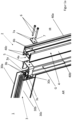
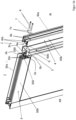
- the profile arrangement 2 comprises a first profile element 3 designed as a horizontal profile, a second profile element 4 designed as a vertical profile, a profile connector element 5, which is U-shaped when viewed in cross section and which has two leg parts 5a and a base part 5b connecting the two leg parts 5a at one end, and at least one fastening means 6, here in the form of a screw, for fastening the two profile elements 3; 4 using the profile connector element 5 to connect to each other.
- the door element 1 (partially shown) essentially consists of a frame, which is formed by two horizontal profiles 3 and two vertical profiles 4 and a glass pane G accommodated by these and introduced into U-shaped recesses in the profile elements, as well as corresponding small parts and seals.
- the four connector corners of the door frame are preferably in the same way as here in figure 1 described for a corner, trained.
- the first profile element 3 has two guide channels 3a, which extend in the longitudinal direction of the profile, for receiving the two leg parts 5a of the profile connector element 5, in particular in a form-fitting manner. Furthermore, the first profile element 3 has two fastening channels 3b for receiving the at least one fastening means 6 in a non-positive or non-positive manner.
- the second profile element 4 has a U-shaped recess 4a viewed in cross section for receiving the profile connector element 5, with the profile connector element 5 in its base part 5b and the second profile element 4 in the bottom of its U-shaped recess 4a having two mounting openings corresponding to the fastening channels 3b of the first profile element 3 4b for the passage of the two fastening means 6.
- two screws are preferably used as fastening means 6, which are passed through two assembly openings 4b in the second profile element 4 and through two corresponding assembly openings 5c in the profile connector element 5 and are screwed into corresponding fastening channels 3b in the first profile element 3.
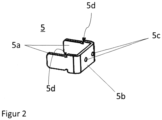
- the profile connector element 5 is preferably made from a steel sheet with a thickness of about four mm, on the one hand to ensure simple production by stamping and bending and on the other hand to have sufficient strength to carry corresponding profile or door element loads.
- an intermediate plate 7 with two assembly openings 7a is used, which is placed under the screw heads of the fastening means 6 in the form of a washer.
- At least one leg part 5a of the profile connector element 5 is designed in such a way that, starting from its free leg end to be inserted into the guide channel 3a of the first profile element 3, the leg part 5a has a stepped widening 5d before it reaches the base part 5b (see also figure 2 ) has, via which the first profile element 3 is partially supported on the front side in the assembled state.
- Each profile element 3; 4 is designed in several parts and comprises at least a first profile shell part arranged in the direction of an interior IR 30a; 40a and a second profile shell part 30b arranged in the direction of an exterior space AR; 40b.
- the two profile shell parts 30a, 30b; 40a, 40b are connected via at least one insulating element 30c; 40c thermally separated from each other, connected to each other.
- a guide channel 3a is formed in each of the two profile shell parts 30a, 30b of the first profile element 3.
- a flexible connection between the profile shell part 40a arranged in the direction of the interior IR and the profile shell part 40b arranged in the direction of the exterior AR is ensured via the insulating element 40c itself (e.g. its material-related and/or structural, possibly multi-part structure) or via the connection of the insulating element 40c to one of the two connected profile shell parts 40a, 40b.
- a flexible connection is understood to mean that relative displaceability is ensured by the fact that even with the use of an average manual force, which can be used to displace the profile shell parts that are to be displaced relative to one another.
- each existing fastening channel 3b of the first profile element 3 is arranged in the profile shell part 30a designed for the interior IR (or arranged in its direction).
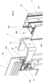
- figure 4 is the profile arrangement 2 with a horizontal profile 4 and a vertical profile 3, which form a frame corner of a door element 1, shown in an assembled or screwed state.
- the reference to the interior and exterior refers to the temperature conditions in or on the profile shell parts (which have been "assigned" to the exterior or interior) and one could alternatively speak of the warm side of the profile instead of the exterior (outside of the profile exposed to the sun) and of the cold side of the profile instead of the interior, since it is about the temperature equalization between two profile shells with very different temperatures, one of which (e.g. due to UV radiation or solar radiation) is considerably warmer than the other and it is caused by this corresponding expansions of the profile elements or their profile shell parts can occur.
Description
Die vorliegende Erfindung betrifft eine Profilanordnung, insbesondere für Türsysteme zur Trennung eines Innenraums von einem Außenraum, umfassend ein erstes als Horizontalprofil ausgebildetes Profilelement, ein zweites als Vertikalprofil ausgebildetes Profilelement, ein Profilverbinderelement, welches U-förmig ausgebildet ist und welches zwei Schenkelteile sowie ein die beiden Schenkelteile an einem Ende verbindendes Basisteil aufweist, sowie mindestens ein Befestigungsmittel, um die beiden Profilelemente unter Verwendung des Profilverbinderelements miteinander zu verbinden. Das erste Profilelement weist sich in Profillängsrichtung erstreckende Führungskanäle zur vorzugsweise formschlüssigen Aufnahme der beiden Schenkelteile des Profilverbinderelements auf. Ferner weist das erste Profilelement mindestens einen Befestigungskanal zur kraftschlüssigen oder kraftformschlüssigen Aufnahme des mindestens einen Befestigungsmittels auf. Das zweite Profilelement weist im Querschnitt gesehen eine U-förmige Ausnehmung zur bereichsweisen Aufnahme des Profilverbinderelements auf. Das Profilverbinderelement weist in seinem Basisteil und das zweite Profilelement im Boden seiner U-förmigen Ausnehmung jeweils zumindest eine mit dem Befestigungskanal des ersten Profilelements korrespondierende Montageöffnung zur Hindurchführung des Befestigungsmittels auf.The present invention relates to a profile arrangement, in particular for door systems for separating an interior space from an exterior space, comprising a first profile element designed as a horizontal profile, a second profile element designed as a vertical profile, a profile connector element which is U-shaped and which has two leg parts and a base part connecting the two leg parts at one end, and at least one fastening means to connect the two profile elements to one another using the profile connector element. The first profile element has guide channels extending in the longitudinal direction of the profile for preferably receiving the two leg parts of the profile connector element in a form-fitting manner. Furthermore, the first profile element has at least one fastening channel for receiving the at least one fastening means in a non-positive or non-positive manner. Seen in cross section, the second profile element has a U-shaped recess for accommodating the profile connector element in certain areas. The profile connector element has in its base part and the second profile element in the bottom of its U-shaped recess in each case at least one mounting opening corresponding to the fastening channel of the first profile element for the passage of the fastening means.
Aus dem Stand der Technik sind diverse Profilanordnungen und Eckverbinder für Profilanordnungen bekannt. Eine Profilanordnung gemäß dem Oberbegriff des Patentanspruchs 1 ist aus der
Es ist Aufgabe der vorliegenden Erfindung, eine Profilanordnung zu schaffen, die zum einen eine thermische Trennung zwischen Innen- und Außenseite der Profilelemente eines Profilrahmens gewährleistet und die zum anderen ein Verbiegen und Verziehen des Profilrahmens weitestgehend ausschließt beziehungsweise diesem entsprechend entgegenwirkt.It is the object of the present invention to create a profile arrangement which on the one hand ensures a thermal separation between the inside and outside of the profile elements of a profile frame and on the other hand largely excludes or counteracts bending and warping of the profile frame.
Voranstehende Aufgabe wird durch die Gesamtheit der Merkmale des unabhängigen Patentanspruchs 1 gelöst. Demnach wird die Aufgabe durch eine Profilanordnung gelöst, bei der ausgehend von einer gattungsgemäßen Profilanordnung in einer erfindungsgemäßen Weiterbildung zumindest das zweite, als Vertikalprofil ausgebildete, Profilelement mehrteilig ausgebildet ist und zumindest ein erstes, in Richtung eines Innenraums angeordnetes, Profilschalenteil und ein zweites, in Richtung eines Außenraums angeordnetes, Profilschalenteil aufweist, wobei die Profilschalenteile über mindestens ein Isolierelement (z.B. Isolierprofil bzw- steg), thermisch voneinander getrennt, miteinander verbunden sind. Des Weiteren ist gemäß der Erfindung zumindest im zweiten Profilelement vorgesehen über das Isolierelement selbst oder über die Anbindung des Isolierelements an eines der beiden verbundenen Profilschalenteile eine schubweiche Verbindung zwischen dem in Richtung Innenraum angeordneten Profilschalenteil und dem in Richtung Außenraum angeordneten Profilschalenteil zu realisieren, derart, dass eine relative Verschiebbarkeit in Profillängsrichtung zwischen den beiden Profilschalenteilen des zweiten Profilelements gewährleistet ist. Unter schubweicher Verbindung im Sinne der Erfindung ist eine Verbindung mit äußerem und innerem Profilschalenteil, die über ein Isolierelement(profil) miteinander verbunden sind zu verstehen, bei der die Profilschalenteile durch maximal eine mittlere Handkraft gegeneinander verschiebbar sind. Hierfür ist eine entsprechend schubweiche Verbindung zwischen einem der beiden Schalenteile und dem Isolierelement(profil) ausgebildet. Bevorzugt ist die Verbindung zwischen dem anderen Profilschalenteil und dem Trennelement(profil) schubfest (also nicht gegeneinander verschiebbar) ausgebildet.The above object is achieved by the features of
Durch die erfindungsgemäße Lösung wird eine Profilanordnung - mit vorzugsweise als Aluminiumprofil ausgebildeten Profilelementen - geschaffen, die aufgrund von Temperaturunterschieden zwischen Innenraum und Außenraum auftretende Materialspannungen (die aufgrund der Flächenverhältnisse vor allen Dingen durch die Vertikalprofile bedingt sind) ausgleicht und ein etwaiges Verziehen des Profilrahmens weitestgehend unterbindet. Dies ermöglicht es beispielsweise bei einer Profilanordnung mit Profilelementen aus Aluminium o.d., dem in Richtung Außenraum angeordneten Profilschalenteil des Vertikalprofilelements, bei Erwärmung (wodurch das äußere Profilschalenteil gegenüber dem inneren Profilschalenteil unterschiedlich erwärmt ist), eine im Wesentlichen ungehinderte Ausdehnung in Profillängsrichtung vorzunehmen - beim Vertikalprofil eines Türflügelelements also nach oben und unten, da die Außenschale hier nicht zwischen oben und unten quer verlaufenden Schraubverbindungen "eingespannt" ist, sondern sich axial frei bewegen kann gegenüber dem Rücken des in der im Querschitt gesehen U-förmig ausgebildeten Aufnahme des zweiten Profilelements (welche beispielsweise auch den Glaskanal zur Aufnahme einer thermisch isolierenden Mehrfachglasscheibe bildet) angeordneten Profilverbinderelements.The solution according to the invention creates a profile arrangement - with profile elements preferably designed as an aluminum profile - which compensates for material stresses that occur due to temperature differences between the interior and exterior (which are primarily caused by the vertical profiles due to the surface ratios) and largely prevents any warping of the profile frame. This makes it possible, for example, in a profile arrangement with profile elements made of aluminum or the profile shell part of the vertical profile element arranged in the direction of the outside space, when heated (whereby the outer profile shell part is heated differently compared to the inner profile shell part), an essentially unhindered expansion in the longitudinal direction of the profile - in the case of the vertical profile of a door leaf element, i.e. upwards and downwards, since the outer shell is not "clamped" between top and bottom transverse screw connections, but can move axially freely compared to the back of the U -shaped receptacle of the second profile element (which, for example, also forms the glass channel for receiving a thermally insulating multiple pane of glass) arranged profile connector element.
Bevorzugte Weiterbildungen der Erfindung sind in den Unteransprüchen definiert.Preferred developments of the invention are defined in the dependent claims.
In einer möglichen Weiterbildung der Erfindung ist das erste als Horizontalprofil ausgebildete Profilelement analog (nicht identisch) zu dem als Vertikalprofil ausgebildeten zweiten Profilelement mehrteilig ausgebildet und weist zumindest ein erstes, in Richtung eines Innenraums angeordnetes, Profilschalenteil und ein zweites, in Richtung eines Außenraums angeordnetes, Profilschalenteil auf, wobei die Profilschalenteile über mindestens ein Isolierelement (z.B. Isolierprofil bzw- steg), thermisch voneinander getrennt, miteinander verbunden sind. Hierdurch wird die thermische Trennung zwischen den beiden Profilseiten der Profilanordnung weiter verbessert. Durch den in Teilen gleichen Profilaufbau von Vertikal- und Horizontalprofilelement, und die damit verbundene Reduzierung von unterschiedlichen Teilen, können ferner auch noch Kostenvorteile erzielt werden.In one possible development of the invention, the first profile element designed as a horizontal profile is designed in multiple parts analogously (not identically) to the second profile element designed as a vertical profile and has at least a first profile shell part arranged in the direction of an interior space and a second profile shell part arranged in the direction of an outer space, the profile shell parts being thermally separated from one another and connected to one another via at least one insulating element (e.g. insulating profile or web). This further improves the thermal separation between the two profile sides of the profile arrangement. Due to the profile structure of the vertical and horizontal profile elements being the same in parts, and the associated reduction in different parts, cost advantages can also be achieved.
Bevorzugt ist ferner in jedem der beiden Profilschalenteile des ersten Profilelements jeweils ein Führungskanal ausgebildet, was wiederum der Stabilität der Profilanordnung zu Gute kommt.Furthermore, a guide channel is preferably formed in each of the two profile shell parts of the first profile element, which in turn benefits the stability of the profile arrangement.
Insbesondere ist vorgesehen, jeden Befestigungskanal des ersten Profilelements ausschließlich in dem für den Innenraum (bzw. die Kaltseite) konzipierten Profilschalenteil anzuordnen. Auf diese Weise wird die Fähigkeit der Ausdehnung des gesamten Rahmenelements verbessert.In particular, it is provided that each fastening channel of the first profile element is arranged exclusively in the profile shell part designed for the interior (or the cold side). In this way, the ability to expand the entire frame member is improved.
Mit Vorteil ist der mindestens eine Befestigungskanal als Schraubkanal ausgeführt - besonders bevorzugt als Schraubkanal in den bei der erstmaligen Montage das Gewinde mittels des als Schraube ausgeführten Befestigungsmittels eingeschnitten wird.The at least one fastening channel is advantageously designed as a screw channel—particularly preferably as a screw channel into which the thread is cut by means of the fastening means designed as a screw during initial assembly.
Bevorzugt besteht jedes Isolierelement aus einem Kunststoffmaterial oder einem Kompositmaterial mit Kunststoffkomponenten, welches entsprechend optimierte Eigenschaften im Hinblick auf eine thermische Trennung gewährleistet.Each insulating element preferably consists of a plastic material or a composite material with plastic components, which is appropriate optimized properties with regard to thermal separation.
Das Profilverbinderelement ist bevorzugt aus Stahlblech hergestellt und weist insbesondere eine Dicke von mindestens 3 mm - besonders bevorzugt eine Dicke von 4 mm - auf.The profile connector element is preferably made of sheet steel and in particular has a thickness of at least 3 mm--particularly preferably a thickness of 4 mm.
Zumindest ein Schenkelteil des Profilverbinderelements ist mit Vorteil derart ausgebildet, dass ausgehend von seinem freien, in den Führungskanal des ersten Profilelements einzuführenden Schenkelende, das Schenkelteil vor Erreichen des Basisteils eine stufenförmige Verbreiterung aufweist, über die sich das erste Profilelement im montierten Zustand bereichsweise stirnseitig abstützt. Durch diese beidseitig ausgebildeten vertikalen Stufen in der Kontur der freien Schenkelteile auf Höhe der Berührungsebene von Horizontalprofil und Vertikalprofil wird eine definierte Anlagekante des Profilverbinderlements (und damit der freien Seitenwandungskanten der U-förmigen Ausnehmung des zweiten Profilelements) an der Stirnfläche des ersten Profilelements (Horizontalprofil) gebildet und wird ferner die Aufnahme der durch die Verschraubung erzeugten Zugkräfte bei gleichzeitiger Sicherstellung eines spaltfreien Übergangs der Profilelemente im Stoßbereich bzw. Anbindungsbereich gewährleistet. Vorzugsweise teilt sich die Stufe zu gleichen Anteilen beidseitig der Schenkel auf, sodass sich eine zu einer horizontalen Mittelebene symmetrische Form des Verbinderelements ergibt (für universellen Einsatz rechts und links bzw. oben und unten). Die Position der Stufe am Verbinderelement, bezogen auf die im Vertikalprofil anliegende Fläche eines Schenkelteils, entspricht hierbei dem Tiefenmaß des Glasaufnahmekanals im Vertikalprofil.At least one leg part of the profile connector element is advantageously designed in such a way that, starting from its free leg end, which is to be inserted into the guide channel of the first profile element, the leg part has a stepped widening before it reaches the base part, via which the first profile element is supported in some areas on the front side in the assembled state. Due to these vertical steps formed on both sides in the contour of the free leg parts at the level of the contact plane of the horizontal profile and vertical profile, a defined contact edge of the profile connector element (and thus the free side wall edges of the U-shaped recess of the second profile element) is formed on the end face of the first profile element (horizontal profile) and the absorption of the tensile forces generated by the screw connection is also ensured while at the same time ensuring a gap-free transition of the profile elements in the joint area or connection area. The step is preferably divided equally on both sides of the legs, resulting in a shape of the connector element that is symmetrical to a horizontal center plane (for universal use on the right and left or top and bottom). The position of the step on the connector element, based on the surface of a leg part lying against it in the vertical profile, corresponds to the depth dimension of the glass receiving channel in the vertical profile.
Vorzugsweise weist das erste Profilelement in seinem in Richtung Innenraum angeordneten Profilschalenteil zumindest zwei Befestigungskanäle auf, wobei das zweite Profilelement an das erste Profilelement mittels zwei mit den Befestigungskanälen korrespondierenden Befestigungsmitteln über das Verbinderelement (mit korrespondierenden Montageöffnungen im Basisteil) mit dem ersten Profilelement verbunden beziehungsweise über das Verbinderelement mit dem ersten Profilelement verbindbar ist. Die Fixierung des Verbinderelements erfolgt bevorzugt mittels Schraubverbindung(en) durch mindestens eine Profilwandung (entweder in einer der Aluminiumschalen, im Isolierelement, oder in einer Kombination aus Aluminiumschale(n) und Isolierelement) im Vertikalprofil. Die betroffene(n) Profilwandung(en) weisen hierzu die mit den Positionen der Befestigungs- bzw. Schraubkanäle im Horizontalprofil sowie dem Lochbild (Montageöffnungen) im Basisteil des Verbinderelements korrespondierenden Durchgangsbohrungen (Montageöffnungen der bodenseitigen Profilwandung der U-förmigen Ausnehmung des zweiten Profilelements) auf. Mit Vorteil sind zumindest zwei Montageöffnungen im zweiten Profilelement vorhanden, die mit zwei Montageöffnungen im Profilverbinderelement korrespondieren, wobei bevorzugt eine der Montageöffnungen in der Profilwandung des ersten Profilschalenteils und eine andere Montageöffnung bereichsweise in der Profilwandung des ersten Profilschalenteils und bereichsweise in der Profilwandung des thermischen Trennelements (also quasi auf der Trennlinie zwischen dem Profil des ersten Profilschalenteils und dem als Profil ausgebildeten Trennelement) angeordnet ist. Denkbar ist ebenfalls eine der Montageöffnungen im Profilschalenteil und eine weitere Montageöffnung im Profil des Trennelements auszubilden.The first profile element preferably has at least two fastening channels in its profile shell part arranged in the direction of the interior on, wherein the second profile element is connected to the first profile element by means of two fastening means corresponding to the fastening channels via the connector element (with corresponding assembly openings in the base part) to the first profile element or can be connected to the first profile element via the connector element. The connector element is preferably fixed by means of screw connection(s) through at least one profile wall (either in one of the aluminum shells, in the insulating element, or in a combination of aluminum shell(s) and insulating element) in the vertical profile. For this purpose, the affected profile wall(s) have the through holes (installation openings in the bottom profile wall of the U-shaped recess of the second profile element) corresponding to the positions of the fastening or screw channels in the horizontal profile and the hole pattern (assembly openings) in the base part of the connector element. There are advantageously at least two assembly openings in the second profile element, which correspond to two assembly openings in the profile connector element, with one of the assembly openings preferably being arranged in the profile wall of the first profile shell part and another assembly opening being arranged in regions in the profile wall of the first profile shell part and in regions in the profile wall of the thermal separating element (that is to say on the dividing line between the profile of the first profile shell part and the separating element designed as a profile). It is also conceivable to form one of the assembly openings in the profile shell part and another assembly opening in the profile of the separating element.
Zur Verteilung von durch die Schraubverbindung auftretenden Kräften ist vorzugsweise eine Zwischenplatte mit, mit den Montageöffnungen des zweiten Profilelements korrespondierenden, Montageöffnungen vorhanden, die nach Art einer Unterlegscheibe eine zu hohe Krafteinwirkung im Bereich des mindestens einen Isolierstegs unterbindet. Durch die auf diese Weise reduzierte Flächenpressung der Schraubköpfe wird ein späteres "Setzen" im Kontaktbereich Zwischen Schraubenkopf und (Aluminium-)Profil verhindert. Besonders bevorzugt ist die Zwischenplatte derart ausgebildet, dass sie sich im montierten Zustand an beiden Profilschalenteilen des zweiten Profilelements abstützt. Hierdurch wird eine optimierte Kräfteverteilung innerhalb des zweiten Profilelements erreicht.To distribute forces occurring through the screw connection, there is preferably an intermediate plate with mounting openings corresponding to the mounting openings of the second profile element, which, like a washer, prevents excessive force from being applied in the area of the at least one insulating bar. Through on this The reduced surface pressure of the screw heads prevents later "settling" in the contact area between the screw head and the (aluminium) profile. The intermediate plate is particularly preferably designed in such a way that, in the assembled state, it is supported on both profile shell parts of the second profile element. This achieves an optimized distribution of forces within the second profile element.
Eine erfindungsgemäße Profilanordnung nachfolgend anhand von Zeichnungen näher erläutert. Es zeigen jeweils schematisch:
- Figur 1a
- ein Türelement ausschnittsweise dargestellt, mit einer Profilanordnung gemäß der Erfindung in Perspektivansicht in teilweiser Explosionsdarstellung,
- Figur 1b
- ein Türelement gemäß
Figur 1a in einer etwas anderen Perspektivansicht, Figur 2- ein Profilverbinderelement gemäß
Figur 1a und1b in vergrößerter perspektivischer Einzeldarstellung, Figur 3- eine vergrößerte Teilansicht der in
Figur 1 Figur 4- eine Teilansicht der in
Figur 1
- Figure 1a
- a door element shown in part, with a profile arrangement according to the invention in a perspective view in a partially exploded view,
- Figure 1b
- a door element according to
Figure 1a in a slightly different perspective, - figure 2
- a profile connector element according to
Figure 1a and1b in an enlarged perspective individual representation, - figure 3
- an enlarged partial view of the
figure 1 shown profile arrangement in exploded view, - figure 4
- a partial view of the in
figure 1 Profile arrangement shown in the assembled (connected) state.
In den
Das erste Profilelement 3 weist zwei sich in Profillängsrichtung erstreckende Führungskanäle 3a zur insbesondere formschlüssigen Aufnahme der beiden Schenkelteile 5a des Profilverbinderelements 5 auf. Ferner weist das erste Profilelement 3 zwei Befestigungskanäle 3b zur kraftschlüssigen oder kraftformschlüssigen Aufnahme des mindestens einen Befestigungsmittels 6 auf.The
Das zweite Profilelement 4 weist eine im Querschnitt gesehen U-förmige Ausnehmung 4a zur Aufnahme des Profilverbinderelements 5 auf, wobei das Profilverbinderelement 5 in seinem Basisteil 5b und das zweite Profilelement 4 im Boden seiner U-förmigen Ausnehmung 4a zwei mit den Befestigungskanälen 3b des ersten Profilelements 3 korrespondierende Montageöffnungen 4b zur Hindurchführung der zwei Befestigungsmittel 6 aufweist.The
Im dargestellten Ausführungsbeispiel sind bevorzugt zwei Schrauben als Befestigungsmittel 6 verwendet, die durch zwei Montageöffnungen 4b des zweiten Profilelements 4 sowie durch zwei hiermit korrespondierende Montageöffnungen 5c des Profilverbinderelements 5 hindurchgeführt und in korrespondierenden Befestigungskanälen 3b des ersten Profilelements 3 verschraubt sind. Das Profilverbinderelement 5 ist bevorzugt aus einem Stahlblech mit zirka vier mm Dicke gefertigt, um zum einen eine einfache Fertigung durch Stanzen und Biegen zu gewährleisten und um zum anderen eine ausreichende Festigkeit aufzuweisen um entsprechende Profil- bzw. Türelementlasten tragen zu können. Um bei der Schraubverbindung der Profilelemente 3; 4 auftretende Schraubkräfte zu verteilen und punktuelle Höchstbelastungen zu vermeiden wird eine Zwischenplatte 7 mit zwei Montageöffnungen 7a verwendet, welche in Form einer Unterlegscheibe den Schraubenköpfen der Befestigungsmittel 6 untergelegt ist. Um auftretende Kantenspannungen im Bereich (potentiellen Kontaktbereich) der Profilkanten 300; 400 der zu verbindenden Profilelemente 3; 4 weitestgehend zu unterbinden und gleichzeitig eine möglichst spaltfreie Verbindung derselben zu gewährleisten, ist zumindest ein Schenkelteil 5a des Profilverbinderelements 5 derart ausgebildet, dass ausgehend von seinem freien, in den Führungskanal 3a des ersten Profilelements 3 einzuführenden Schenkelende das Schenkelteil 5a vor Erreichen des Basisteils 5b eine stufenförmige Verbreiterung 5d (siehe auch
Jedes Profilelement 3; 4 ist mehrteilig ausgebildet und umfasst zumindest ein erstes, in Richtung eines Innenraums IR angeordnetes, Profilschalenteil 30a; 40a und ein zweites, in Richtung eines Außenraums AR angeordnetes, Profilschalenteil 30b; 40b. Die beiden Profilschalenteile 30a, 30b; 40a, 40b sind über mindestens ein als Isoliersteg ausgebildetes Isolierelement 30c; 40c thermisch voneinander getrennt, miteinander verbunden.Each
In jedem der beiden Profilschalenteile 30a, 30b des ersten Profilelements 3 ist dabei jeweils ein Führungskanal 3a ausgebildet.A
Im zweiten Profilelement 4 ist über das Isolierelement 40c selbst (beispielsweise seinen materialtechnischen und/oder konstruktiven, ggf. mehrteiligen, Aufbau) oder über die Anbindung des Isolierelements 40c an eines der beiden verbundenen Profilschalenteile 40a, 40b eine schubweiche Verbindung zwischen dem Richtung Innenraum IR angeordneten Profilschalenteil 40a und dem Richtung Außenraum AR angeordneten Profilschalenteil 40b gewährleistet. Unter schubweicher Verbindung im Sinne dieser Erfindung wird verstanden, dass eine relative Verschiebbarkeit gewährleistet ist, indem bereits bei Einsatz einer mittleren Handkraft, durch die man angreifend an den relativ zueinander zu verschiebenden Profilschalenteilen, diese gegeneinander verschieben kann).In the
Um die beschriebene Relativverschiebbarkeit zwischen Isolierelement 40c und einem der Profilschalenteile 40a, 40b zu gewährleisten ist jeder vorhandene Befestigungskanal 3b des ersten Profilelements 3 ist in dem für den Innenraum IR konzipierten (bzw. in dessen Richtung angeordneten) Profilschalenteil 30a angeordnet.In order to ensure the described relative displaceability between the insulating
Im dargestellten Ausführungsbeispiel mit zwei Befestigungsmitteln 6 - von denen ein Befestigungsmittel 6 durch eine Montageöffnung 4b im Isolierelement 40c des zweiten Profilelements 4 in einem hiermit korrespondierenden Befestigungskanal 3b des dem Richtung Innenraum IR angeordneten Profilschalenteils 30a des ersten Profilelements 3 festgelegt ist - muss die Relativbeweglichkeit zwischen dem Isolierelement 40c und dem in Richtung Außenraum AR orientierten Profilschalenteil 40b zweiten Profilelements 4 ausgebildet sein.In the exemplary embodiment shown with two fastening means 6 - one of which fastening means 6 is fixed through a mounting
In
Es versteht sich, dass die Bezugnahme im Hinblick auf Innenraum und Außenraum sich auf die Temperaturverhältnisse in oder an den Profilschalenteilen bezieht (die dem Außen- bzw- Innenraum "zugeordnet" worden sind) und man alternativ auch anstelle von Außenraum (von der Sonne bestrahlte Profilaußenseite) auch von Profilwarmseite und anstelle von Innenraum von Profilkaltseite sprechen könnte, da es um den Temperaturausgleich zwischen zwei sehr unterschiedlich temperierten Profilschalen geht von denen eine (z.B. durch UV-Bestrahlung bzw. Sonnenbestrahlung) erheblich wärmer ist als die andere und es hierdurch bedingt zu entsprechenden Ausdehnungen der Profilelemente oder deren Profilschalenteilen kommen kann.It goes without saying that the reference to the interior and exterior refers to the temperature conditions in or on the profile shell parts (which have been "assigned" to the exterior or interior) and one could alternatively speak of the warm side of the profile instead of the exterior (outside of the profile exposed to the sun) and of the cold side of the profile instead of the interior, since it is about the temperature equalization between two profile shells with very different temperatures, one of which (e.g. due to UV radiation or solar radiation) is considerably warmer than the other and it is caused by this corresponding expansions of the profile elements or their profile shell parts can occur.
- 11
- Türelementdoor panel
- 22
- Profilanordnungprofile arrangement
- 33
- erstes Pofilelement (Horizontalprofil)first profile element (horizontal profile)
- 3a3a
- Führungskanalguide channel
- 3b3b
- Befestigungskanalmounting channel
- 30a30a
- erstes Profilschalenteil (Richtung IR angeordnet)first profile shell part (arranged towards IR)
- 30b30b
- zweites Profilschalenteil (Richtung AR angeordnet)second profile shell part (arranged in direction AR)
- 30c30c
- Isolierelementinsulating element
- 300300
- Profilkanteprofile edge
- 44
- zweites Pofilelement (Vertikalprofil)second profile element (vertical profile)
- 4a4a
- Ausnehmungrecess
- 4b4b
- Montageöffnungmounting hole
- 40a40a
- erstes Profilschalenteil (Richtung IR angeordnet)first profile shell part (arranged towards IR)
- 40b40b
- zweites Profilschalenteil (Richtung AR angeordnet)second profile shell part (arranged in direction AR)
- 40c40c
- Isolierelementinsulating element
- 400400
- Profilkanteprofile edge
- 55
- Profilverbinderelementprofile connector element
- 5a5a
- Schenkelteilthigh part
- 5b5b
- Basisteilbase part
- 5c5c
- Montageöffnungmounting hole
- 5d5d
- stufenförmige Verbreiterungstepped broadening
- 66
- Befestigungselementfastener
- 77
- Zwischenplatteintermediate plate
- 7a7a
- Montageöffnungmounting hole
- IRIR
- Innenrauminner space
- ARAR
- Außenraumoutdoor space
- GG
- Glasscheibeglass pane
Claims (10)
- A profile system (2), in particular for door systems for separating an interior space from an exterior space, comprising- a first profile element (3) designed as a horizontal profile,- a second profile element (4) designed as a vertical profile,- a profile connector element (5) which is designed to be U-shaped and which has two leg parts (5a) and a base part (5b) connecting the two leg parts (5a) at one end,- as well as at least one fastening means (6) to connect the two profile elements (3; 4) to one another using the profile connector element (5),- wherein the first profile element (3) has guide channels (3a) extending in the profile longitudinal direction for receiving the two leg parts (5a) of the profile connector element (5),- wherein the first profile element (3) has at least one fastening channel (3b) for receiving the at least one fastening means (6) in a non-positive or non-positive manner,- wherein the second profile element (4), when viewed in cross section, has a U-shaped recess (4a) for receiving the profile connector element (5) in certain areas, and the profile connector element (5) in its base part (5b) and the second profile element (4) in the bottom of its U-shaped recess (4a) has at least one assembly opening (5c; 4b) corresponding to the fastening channel (3b) of the first profile element (3) for the passage of the fastening means (6),
characterized in that- at least the second profile element (4) is designed in multiple parts and has at least one first profile shell part (40a) arranged in the direction of an interior space (IR) and a second profile shell part (40b) arranged in the direction of an exterior space (AR), wherein the profile shell parts (40a, 40b) are connected to one another and thermally separated from one another via at least one insulating element (40c),- - and wherein, at least in the second profile element (4), via the insulating element (40c) itself or via the connection of the insulating element (40c) to one of the two connected profile shell parts (40a, 40b), a thrust-flexible connection is ensured between the profile shell part (40a) arranged in the direction of the interior space (IR) and the profile shell part (40b) arranged in the direction of the exterior space (AR) in such manner that relative displaceability is ensured in the profile longitudinal direction between the two profile shell parts (40a, 40b) of the second profile element (4). - The profile system (2) according to claim 1,
characterized in that the first profile element (3) is designed in multiple parts and has at least one first profile shell part (30a) arranged in the direction of an interior space (IR) and a second profile shell part (30b) arranged in the direction of an exterior space (AR), wherein the profile shell parts (30a, 30b) are connected to one another and thermally separated from one another via at least one insulating element (30c). - The profile system (2) according to claim 2,
characterized in that each fastening channel (3b) of the first profile element (3) is arranged in the profile shell part (30a) designed for the interior space (IR). - The profile system (2) according to claim 2 or 3,
characterized in that in each of the two profile shell parts (30a, 30b) of the first profile element (3) a respective guide channel (3a) is designed. - The profile system (2) according to one of the preceding claims,
characterized in that the at least one fastening channel (3b) is configured as a screw channel, preferably as a screw channel into which, during initial assembly, the thread is cut by means of the fastening means (6) configured as a screw. - The profile system (2) according to one of the preceding claims,
characterized in that at least one leg part (5a) of the profile connector element (5) is designed in such manner that, starting from its free leg end to be introduced into the guide channel (3a) of the first profile element (3), the leg part (5a), before reaching the base part (5b), has a stepped widening (5d) via which the first profile element (3) is supported in certain areas on the front side in the assembled state. - The profile system (2) according to one or more of the preceding claims,
characterized in that the first profile element (3) has at least two fastening channels (3b) in the profile shell part (30a) arranged in the direction of the interior space (IR) and the second profile element (4) is connected to the first profile element (3) by means of two fastening means (6) corresponding to the fastening channels (3b). - The profile system (2) according to one of the preceding claims,
characterized in that there are at least two assembly openings (4b) in the second profile element (4), which correspond to two assembly openings (5c) in the profile connector element (5), and wherein one of the assembly openings (4b) is introduced into the at least one insulating element (40c). - The profile system (2) according to claim 8,
characterized in that there is an intermediate plate (7) with assembly openings (7a) corresponding to the assembly openings (4b) of the second profile element (4), which, in the manner of a washer, prevents excessive force from being applied in the region of the at least one insulating element (40c) and ensures a corresponding distribution of forces and is preferably designed in such manner that, in the assembled state, it is supported on both profile shell parts (40a, 40b) of the second profile element (4). - A door element (1) with a profile system (2) according to one of the preceding claims.
Applications Claiming Priority (2)
| Application Number | Priority Date | Filing Date | Title |
|---|---|---|---|
| DE102019101451.4A DE102019101451A1 (en) | 2019-01-21 | 2019-01-21 | Profile arrangement |
| PCT/EP2020/051431 WO2020152180A1 (en) | 2019-01-21 | 2020-01-21 | Profile system |
Publications (3)
| Publication Number | Publication Date |
|---|---|
| EP3914799A1 EP3914799A1 (en) | 2021-12-01 |
| EP3914799C0 EP3914799C0 (en) | 2023-07-26 |
| EP3914799B1 true EP3914799B1 (en) | 2023-07-26 |
Family
ID=69374271
Family Applications (1)
| Application Number | Title | Priority Date | Filing Date |
|---|---|---|---|
| EP20702417.5A Active EP3914799B1 (en) | 2019-01-21 | 2020-01-21 | Profile system |
Country Status (4)
| Country | Link |
|---|---|
| US (1) | US11840878B2 (en) |
| EP (1) | EP3914799B1 (en) |
| DE (1) | DE102019101451A1 (en) |
| WO (1) | WO2020152180A1 (en) |
Families Citing this family (3)
| Publication number | Priority date | Publication date | Assignee | Title |
|---|---|---|---|---|
| US11131140B2 (en) * | 2018-12-11 | 2021-09-28 | Arconic Technologies Llc | Corner joint clip with self-backing plate |
| ES2940215T3 (en) * | 2019-01-30 | 2023-05-04 | Glass Tech Gmbh | Unit of panels and method for the manufacture and/or supply of said unit of panels |
| EP4080007A1 (en) * | 2021-04-20 | 2022-10-26 | Seu Plastics One Man L.L.C. | Sash with composite stiles |
Family Cites Families (15)
| Publication number | Priority date | Publication date | Assignee | Title |
|---|---|---|---|---|
| US2941855A (en) * | 1958-03-05 | 1960-06-21 | Thonet Ind Inc | Tubular members and coupling means therefor |
| DE4308540A1 (en) * | 1993-03-17 | 1994-09-22 | Schueco Int Kg | Butt joint |
| DE19637858A1 (en) * | 1996-09-17 | 1998-04-02 | Schueco Int Kg | Insulated composite profile for doors, windows or facades |
| DE102008008696A1 (en) * | 2008-02-11 | 2009-08-13 | Dorma Gmbh + Co. Kg | Profile and profile system |
| DE102008008695A1 (en) | 2008-02-11 | 2009-08-13 | Dorma Gmbh + Co. Kg | profile connector |
| EP2453068B1 (en) * | 2010-11-12 | 2016-06-29 | Cuhadaroglu Metal Sanayi Ve Pazarlama Anonim Sirketi | Detachable connection of mullion and transom profiles |
| DE102011008765A1 (en) * | 2011-01-07 | 2012-07-12 | Eduard Hueck Gmbh & Co Kg | Profile arrangement for frame, particularly for door- or window frame or door- or window sash, of frame arrangement, has two profiles, where former profile is aluminum profile and latter profile is plastic profile |
| US8998527B2 (en) * | 2011-03-30 | 2015-04-07 | Oldcastle Building Envelope, Inc. | System for interconnection of structural components |
| US9593702B2 (en) * | 2013-09-20 | 2017-03-14 | Arconic Inc. | Manufacture and method for forming structures and the structures resulting therefrom |
| US9127504B2 (en) * | 2013-10-30 | 2015-09-08 | C. R. Laurence Co., Inc. | Corner assembly for metal framed glass panel doors, windows and wall partitions |
| US9359806B2 (en) * | 2014-03-19 | 2016-06-07 | Gregory Header | Combination marine and stop frame glazed panel and method for the same |
| DE102014115714A1 (en) * | 2014-10-29 | 2016-05-04 | SCHÜCO International KG | Composite profile for doors, windows or façade elements |
| US10107027B1 (en) * | 2017-10-24 | 2018-10-23 | Quaker Window Products Co. | Thermally enhanced multi-component window |
| US11131140B2 (en) * | 2018-12-11 | 2021-09-28 | Arconic Technologies Llc | Corner joint clip with self-backing plate |
| US11180947B2 (en) * | 2019-03-27 | 2021-11-23 | Saleh Alkarram | Corner support assembly for metal framed doors and method of assemblage |
-
2019
- 2019-01-21 DE DE102019101451.4A patent/DE102019101451A1/en active Pending
-
2020
- 2020-01-21 EP EP20702417.5A patent/EP3914799B1/en active Active
- 2020-01-21 US US17/424,076 patent/US11840878B2/en active Active
- 2020-01-21 WO PCT/EP2020/051431 patent/WO2020152180A1/en unknown
Also Published As
| Publication number | Publication date |
|---|---|
| EP3914799C0 (en) | 2023-07-26 |
| WO2020152180A1 (en) | 2020-07-30 |
| EP3914799A1 (en) | 2021-12-01 |
| US20220098924A1 (en) | 2022-03-31 |
| US11840878B2 (en) | 2023-12-12 |
| DE102019101451A1 (en) | 2020-07-23 |
Similar Documents
| Publication | Publication Date | Title |
|---|---|---|
| EP3914799B1 (en) | Profile system | |
| DE102006015876A1 (en) | Crashbox and damping arrangement with Crasbox | |
| EP2504511B1 (en) | Strap part of a strap hinge | |
| EP3699386B1 (en) | Automatic door seal with a guiding means for guiding a push rod and a method for positioning the guiding means in a housing of the seal | |
| WO2008110248A1 (en) | Device with a mounting insert for fastening fitting parts to hollow profiles and method for attaching said mounting insert to the hollow profile | |
| EP3667005B1 (en) | Hinge system, vehicle structure, vehicle and method for mounting a door | |
| EP0551836B1 (en) | Screw joint between a profile and a fitting or other structural member | |
| DE202012100233U1 (en) | System comprising a hollow profile and a band tab of a band, as well as hinge tabs | |
| DE102017005781A1 (en) | Hinge for a door or a window and door or window equipped with it | |
| EP2754803B1 (en) | Espagnolette fitting for a window or door and driving rod for such an espagnolette fitting | |
| EP2708693B1 (en) | Sliding leaf frame | |
| EP1445410B1 (en) | Door sill for a lift system | |
| DE102016125602B4 (en) | Insulating body for multi-layer components | |
| EP1205128B1 (en) | Shelf | |
| EP2754805A2 (en) | Locking bar for an espagnolette fitting | |
| DE10028802A1 (en) | Profile for use in double glazing unit has cavities on cold and warm sides connected by narrow central section which reduces heat transfer by conduction | |
| EP1645211B1 (en) | Drawer with stabilising device | |
| DE202011108692U1 (en) | Hollow profile and hall frame with such a profile | |
| EP3121356B1 (en) | Assembly of a hinge on a hollow chamber profile | |
| EP3299531B1 (en) | Cover plate of a suspended ceiling with toolless operable locking element | |
| EP1602836B1 (en) | Stiffening ridge for solid wood | |
| DE102011008765A1 (en) | Profile arrangement for frame, particularly for door- or window frame or door- or window sash, of frame arrangement, has two profiles, where former profile is aluminum profile and latter profile is plastic profile | |
| DE102007034432A1 (en) | Formwork element for circular formwork, has clamping unit moving one locking pin with respect to another locking pin for adjusting distance between locking pins, and clamping device adjusting and determining angle formed between cross bars | |
| EP2754802A2 (en) | Espagnolette fitting for a window or a door | |
| DE60213808T2 (en) | Vehicle body with a connection device |
Legal Events
| Date | Code | Title | Description |
|---|---|---|---|
| STAA | Information on the status of an ep patent application or granted ep patent |
Free format text: STATUS: UNKNOWN |
|
| STAA | Information on the status of an ep patent application or granted ep patent |
Free format text: STATUS: THE INTERNATIONAL PUBLICATION HAS BEEN MADE |
|
| PUAI | Public reference made under article 153(3) epc to a published international application that has entered the european phase |
Free format text: ORIGINAL CODE: 0009012 |
|
| STAA | Information on the status of an ep patent application or granted ep patent |
Free format text: STATUS: REQUEST FOR EXAMINATION WAS MADE |
|
| 17P | Request for examination filed |
Effective date: 20210804 |
|
| AK | Designated contracting states |
Kind code of ref document: A1 Designated state(s): AL AT BE BG CH CY CZ DE DK EE ES FI FR GB GR HR HU IE IS IT LI LT LU LV MC MK MT NL NO PL PT RO RS SE SI SK SM TR |
|
| DAV | Request for validation of the european patent (deleted) | ||
| DAX | Request for extension of the european patent (deleted) | ||
| GRAP | Despatch of communication of intention to grant a patent |
Free format text: ORIGINAL CODE: EPIDOSNIGR1 |
|
| STAA | Information on the status of an ep patent application or granted ep patent |
Free format text: STATUS: GRANT OF PATENT IS INTENDED |
|
| INTG | Intention to grant announced |
Effective date: 20230301 |
|
| GRAS | Grant fee paid |
Free format text: ORIGINAL CODE: EPIDOSNIGR3 |
|
| GRAA | (expected) grant |
Free format text: ORIGINAL CODE: 0009210 |
|
| STAA | Information on the status of an ep patent application or granted ep patent |
Free format text: STATUS: THE PATENT HAS BEEN GRANTED |
|
| AK | Designated contracting states |
Kind code of ref document: B1 Designated state(s): AL AT BE BG CH CY CZ DE DK EE ES FI FR GB GR HR HU IE IS IT LI LT LU LV MC MK MT NL NO PL PT RO RS SE SI SK SM TR |
|
| REG | Reference to a national code |
Ref country code: CH Ref legal event code: EP |
|
| REG | Reference to a national code |
Ref country code: DE Ref legal event code: R096 Ref document number: 502020004372 Country of ref document: DE |
|
| REG | Reference to a national code |
Ref country code: IE Ref legal event code: FG4D Free format text: LANGUAGE OF EP DOCUMENT: GERMAN |
|
| U01 | Request for unitary effect filed |
Effective date: 20230821 |
|
| U07 | Unitary effect registered |
Designated state(s): AT BE BG DE DK EE FI FR IT LT LU LV MT NL PT SE SI Effective date: 20230828 |
|
| REG | Reference to a national code |
Ref country code: LT Ref legal event code: MG9D |
|
| PG25 | Lapsed in a contracting state [announced via postgrant information from national office to epo] |
Ref country code: GR Free format text: LAPSE BECAUSE OF FAILURE TO SUBMIT A TRANSLATION OF THE DESCRIPTION OR TO PAY THE FEE WITHIN THE PRESCRIBED TIME-LIMIT Effective date: 20231027 |
|
| PG25 | Lapsed in a contracting state [announced via postgrant information from national office to epo] |
Ref country code: IS Free format text: LAPSE BECAUSE OF FAILURE TO SUBMIT A TRANSLATION OF THE DESCRIPTION OR TO PAY THE FEE WITHIN THE PRESCRIBED TIME-LIMIT Effective date: 20231126 |
|
| PG25 | Lapsed in a contracting state [announced via postgrant information from national office to epo] |
Ref country code: RS Free format text: LAPSE BECAUSE OF FAILURE TO SUBMIT A TRANSLATION OF THE DESCRIPTION OR TO PAY THE FEE WITHIN THE PRESCRIBED TIME-LIMIT Effective date: 20230726 Ref country code: NO Free format text: LAPSE BECAUSE OF FAILURE TO SUBMIT A TRANSLATION OF THE DESCRIPTION OR TO PAY THE FEE WITHIN THE PRESCRIBED TIME-LIMIT Effective date: 20231026 Ref country code: IS Free format text: LAPSE BECAUSE OF FAILURE TO SUBMIT A TRANSLATION OF THE DESCRIPTION OR TO PAY THE FEE WITHIN THE PRESCRIBED TIME-LIMIT Effective date: 20231126 Ref country code: HR Free format text: LAPSE BECAUSE OF FAILURE TO SUBMIT A TRANSLATION OF THE DESCRIPTION OR TO PAY THE FEE WITHIN THE PRESCRIBED TIME-LIMIT Effective date: 20230726 Ref country code: GR Free format text: LAPSE BECAUSE OF FAILURE TO SUBMIT A TRANSLATION OF THE DESCRIPTION OR TO PAY THE FEE WITHIN THE PRESCRIBED TIME-LIMIT Effective date: 20231027 |
|
| U20 | Renewal fee paid [unitary effect] |
Year of fee payment: 5 Effective date: 20240124 |
|
| PG25 | Lapsed in a contracting state [announced via postgrant information from national office to epo] |
Ref country code: PL Free format text: LAPSE BECAUSE OF FAILURE TO SUBMIT A TRANSLATION OF THE DESCRIPTION OR TO PAY THE FEE WITHIN THE PRESCRIBED TIME-LIMIT Effective date: 20230726 |