EP3228414B1 - Resistance spot welding method - Google Patents
Resistance spot welding method Download PDFInfo
- Publication number
- EP3228414B1 EP3228414B1 EP15865842.7A EP15865842A EP3228414B1 EP 3228414 B1 EP3228414 B1 EP 3228414B1 EP 15865842 A EP15865842 A EP 15865842A EP 3228414 B1 EP3228414 B1 EP 3228414B1
- Authority
- EP
- European Patent Office
- Prior art keywords
- welding
- sheet
- current
- heat generated
- amount
- Prior art date
- Legal status (The legal status is an assumption and is not a legal conclusion. Google has not performed a legal analysis and makes no representation as to the accuracy of the status listed.)
- Active
Links
- 238000003466 welding Methods 0.000 title claims description 138
- 238000000034 method Methods 0.000 title claims description 42
- 230000001186 cumulative effect Effects 0.000 claims description 15
- 238000012360 testing method Methods 0.000 claims description 15
- 230000003044 adaptive effect Effects 0.000 claims description 9
- 238000001816 cooling Methods 0.000 claims description 9
- 229910000831 Steel Inorganic materials 0.000 description 41
- 239000010959 steel Substances 0.000 description 41
- 230000020169 heat generation Effects 0.000 description 7
- 230000015572 biosynthetic process Effects 0.000 description 6
- 238000002844 melting Methods 0.000 description 6
- 230000008018 melting Effects 0.000 description 6
- 229910052751 metal Inorganic materials 0.000 description 5
- 239000002184 metal Substances 0.000 description 5
- 230000007423 decrease Effects 0.000 description 4
- 238000010586 diagram Methods 0.000 description 4
- 230000000694 effects Effects 0.000 description 4
- 229910001209 Low-carbon steel Inorganic materials 0.000 description 3
- 230000002787 reinforcement Effects 0.000 description 3
- 125000006850 spacer group Chemical group 0.000 description 2
- 230000003746 surface roughness Effects 0.000 description 2
- 229910000838 Al alloy Inorganic materials 0.000 description 1
- ZTXONRUJVYXVTJ-UHFFFAOYSA-N chromium copper Chemical compound [Cr][Cu][Cr] ZTXONRUJVYXVTJ-UHFFFAOYSA-N 0.000 description 1
- 230000000052 comparative effect Effects 0.000 description 1
- 238000007796 conventional method Methods 0.000 description 1
- 230000003247 decreasing effect Effects 0.000 description 1
- 230000001419 dependent effect Effects 0.000 description 1
- 230000002349 favourable effect Effects 0.000 description 1
- 230000004927 fusion Effects 0.000 description 1
- 230000003287 optical effect Effects 0.000 description 1
- 230000002093 peripheral effect Effects 0.000 description 1
- 238000003825 pressing Methods 0.000 description 1
- 230000003014 reinforcing effect Effects 0.000 description 1
- 239000002436 steel type Substances 0.000 description 1
Images

Classifications
-
- B—PERFORMING OPERATIONS; TRANSPORTING
- B23—MACHINE TOOLS; METAL-WORKING NOT OTHERWISE PROVIDED FOR
- B23K—SOLDERING OR UNSOLDERING; WELDING; CLADDING OR PLATING BY SOLDERING OR WELDING; CUTTING BY APPLYING HEAT LOCALLY, e.g. FLAME CUTTING; WORKING BY LASER BEAM
- B23K11/00—Resistance welding; Severing by resistance heating
- B23K11/10—Spot welding; Stitch welding
- B23K11/11—Spot welding
- B23K11/115—Spot welding by means of two electrodes placed opposite one another on both sides of the welded parts
-
- B—PERFORMING OPERATIONS; TRANSPORTING
- B23—MACHINE TOOLS; METAL-WORKING NOT OTHERWISE PROVIDED FOR
- B23K—SOLDERING OR UNSOLDERING; WELDING; CLADDING OR PLATING BY SOLDERING OR WELDING; CUTTING BY APPLYING HEAT LOCALLY, e.g. FLAME CUTTING; WORKING BY LASER BEAM
- B23K11/00—Resistance welding; Severing by resistance heating
- B23K11/16—Resistance welding; Severing by resistance heating taking account of the properties of the material to be welded
- B23K11/20—Resistance welding; Severing by resistance heating taking account of the properties of the material to be welded of different metals
-
- B—PERFORMING OPERATIONS; TRANSPORTING
- B23—MACHINE TOOLS; METAL-WORKING NOT OTHERWISE PROVIDED FOR
- B23K—SOLDERING OR UNSOLDERING; WELDING; CLADDING OR PLATING BY SOLDERING OR WELDING; CUTTING BY APPLYING HEAT LOCALLY, e.g. FLAME CUTTING; WORKING BY LASER BEAM
- B23K11/00—Resistance welding; Severing by resistance heating
- B23K11/24—Electric supply or control circuits therefor
- B23K11/25—Monitoring devices
- B23K11/252—Monitoring devices using digital means
- B23K11/255—Monitoring devices using digital means the measured parameter being a force
-
- B—PERFORMING OPERATIONS; TRANSPORTING
- B23—MACHINE TOOLS; METAL-WORKING NOT OTHERWISE PROVIDED FOR
- B23K—SOLDERING OR UNSOLDERING; WELDING; CLADDING OR PLATING BY SOLDERING OR WELDING; CUTTING BY APPLYING HEAT LOCALLY, e.g. FLAME CUTTING; WORKING BY LASER BEAM
- B23K11/00—Resistance welding; Severing by resistance heating
- B23K11/24—Electric supply or control circuits therefor
- B23K11/25—Monitoring devices
- B23K11/252—Monitoring devices using digital means
- B23K11/257—Monitoring devices using digital means the measured parameter being an electrical current
-
- B—PERFORMING OPERATIONS; TRANSPORTING
- B23—MACHINE TOOLS; METAL-WORKING NOT OTHERWISE PROVIDED FOR
- B23K—SOLDERING OR UNSOLDERING; WELDING; CLADDING OR PLATING BY SOLDERING OR WELDING; CUTTING BY APPLYING HEAT LOCALLY, e.g. FLAME CUTTING; WORKING BY LASER BEAM
- B23K11/00—Resistance welding; Severing by resistance heating
- B23K11/36—Auxiliary equipment
- B23K11/362—Contact means for supplying welding current to the electrodes
Definitions
- the disclosure relates to a resistance spot welding method (see, e.g. WO 2014/045431 A1 ).
- the disclosure is particularly intended to ensure a stable nugget diameter without splashing regardless of disturbances such as current shunting or a sheet gap, in a sheet combination of three or more sheets with a high sheet thickness ratio in which a thin sheet is overlapped on at least one face of two or more overlapping thick sheets.
- Resistance spot welding is a method of squeezing two or more overlapping steel sheets by a pair of electrodes from above and below and, while applying an electrode force, passing a high welding current between the upper and lower electrodes for a short time to join the steel sheets. Heat generated from the resistance to the flow of the high welding current is used to obtain a spot weld.
- the spot weld is called a nugget, and results from the overlapping steel sheets melting and solidifying at their contact portion when the current flows through the steel sheets.
- the steel sheets are spot-joined by this nugget.
- the joining strength of the resistance spot weld depends on the nugget diameter. Particularly in the case where high joining strength is required as in automotive parts and the like, it is important to ensure at least a predetermined nugget diameter.
- the nugget diameter gradually increases as the welding current increases.
- splashing occurs.
- Splashing is a phenomenon in which molten metal splatters between the steel sheets. Splashing not only is dangerous, but also degrades appearance as molten metal adheres around the weld, and causes variations in nugget diameter and joint tensile strength. This results in unstable joint quality.
- a center pillar has a structure in which a reinforcement is sandwiched between an outer portion and an inner portion.
- three or more steel sheets need to be overlapped and spot welded, unlike in the case of simply spot welding two overlapping steel sheets.
- the nugget is typically formed by heat generated by volume resistance according to the specific resistance of each steel sheet from near the center between the electrodes. Since the nugget grows large between the thick sheets located near the center between the electrodes before the nugget grows to the thin sheet side, splashing occurs as it cannot be prevented by the applied electrode force. It is therefore difficult to obtain a nugget of a required size between the thin sheet and the thick sheet without splashing in such a sheet combination.
- the outermost thin sheet is the outer portion
- mild steel is often used as the steel sheet because formability is more important than strength.
- the thick sheet is a strength reinforcing member, for which a high tensile strength steel sheet is often used.
- the heat generation position tends to be closer to the high tensile strength steel sheet with high specific resistance. This further hinders the nugget formation between the thick sheet and the thin sheet (mild steel).
- the steel sheet used is a coated steel sheet, the coated layer that has molten at a low temperature expands the current path between the steel sheets, causing a decrease in current density. This makes the nugget formation on the thin sheet side more difficult.
- a nugget of a required size is hard to be formed between the thin and thick sheets in the aforementioned sheet combination of three or more sheets with a high sheet thickness ratio.
- the welding condition for obtaining an appropriate nugget diameter is therefore very limited.
- JP 2003-071569 A proposes the following technique.
- a sheet combination with a high sheet thickness ratio in which a thin sheet is further overlapped on two overlapping thick sheets, a bearing surface one level higher than a general portion is partly formed at the welding position of the thin sheet, and the end of the electrode facing the thin sheet is made spherical.
- the thin sheet and the adjacent thick sheet are welded with a low electrode force so as to crush the bearing surface of the thin sheet.
- the two thick sheets are welded with a high electrode force. A required nugget is thus formed between the thin and thick sheets.
- JP 2003-251469 A proposes the following technique.
- a method of squeezing by a pair of electrode tips, a workpiece in which a thin sheet with low rigidity is overlapped on two thick sheets with high rigidity and spot welding the workpiece, the electrode force applied to the workpiece by the electrode tip in contact with the thin sheet lowest in rigidity is lower than the electrode force applied to the workpiece by the electrode tip in contact with the thick sheet, to form a nugget between the thin and thick sheets.
- the weld strength of the workpiece is thus enhanced.
- JP 2004-358500 A proposes the following technique.
- a method of spot welding parts to be welded with a high sheet thickness ratio after passing a welding current while applying a first electrode force to the parts to be welded, the current passage is stopped, and then a welding current is passed again while applying a second electrode force higher than the first electrode force in the state where the parts to be welded remain squeezed.
- the current value of the welding current in the process of applying the first electrode force is changed in three steps of first to third steps, where the current in the second step is less than the current in each of the first and third steps. The joining strength of the parts to be welded with a high sheet thickness ratio is thus improved.
- the nugget is formed between the thin and thick sheets by setting the electrode force applied to the workpiece by the electrode tip in contact with the thin sheet lowest in rigidity to be lower than the electrode force applied to the workpiece by the electrode tip in contact with the thick sheet.
- the electrode force applied to the workpiece by the electrode tip in contact with the thin sheet is low, the contact area between the thin sheet and the electrode tip is small.
- the range subjected to the electrode force application is reduced, which facilitates splashing when forming a large nugget between the thick sheets.
- a large strain occurs in the workpiece as, after squeezing the workpiece by the electrodes, a welding gun body to which the electrodes are attached is forcibly moved to produce different electrode forces.
- PTL 1 to PTL 3 also have a common problem in that the welding condition for obtaining an appropriate nugget diameter in a sheet combination with a high sheet thickness ratio is very limited. Accordingly, for example in the case where disturbances such as a sheet gap or an existing weld are present, there is a need to derive an appropriate welding condition depending on the size of the sheet gap, the distance to the nearby existing weld, or the like to set an appropriate welding condition for every weld. Deriving such conditions through testing and the like requires considerable time and cost.
- One of the objects of the disclosure is to provide a resistance spot welding method with which a nugget of an appropriate diameter can be obtained without splashing regardless of disturbances such as a sheet gap or current shunting, in a sheet combination with a high sheet thickness ratio in which a thin sheet is overlapped on one face of two or more overlapping thick sheets.
- the disclosure relates to a resistance spot welding method including performing actual welding to squeeze, by a pair of electrodes, a sheet combination in which a thin sheet is overlapped on at least one face of two or more overlapping thick sheets, and passing a current while applying an electrode force to join the sheet combination.
- the disclosure is particularly intended for a sheet combination whose sheet thickness ratio ((the total thickness of the sheet combination)/(the sheet thickness of the thinnest steel sheet (metal sheet) in the sheet combination)) is more than 3 or further 5 or more, for which it has been difficult to obtain a nugget of a required size between the thin and thick sheets without splashing.
- the upper limit of the sheet thickness ratio is not particularly limited, but is typically 12.
- Any welding device that includes a pair of upper and lower electrodes and is capable of freely controlling each of the electrode force and the welding current during welding may be used in the resistance spot welding method according to the disclosure.
- the force mechanism air cylinder, servomotor, etc.
- the type stationary, robot gun, etc.
- the electrode shape, and the like are not particularly limited.
- the term “thin sheet” means a steel sheet with relatively small sheet thickness and the term “thick sheet” means a steel sheet with relatively large sheet thickness, of the steel sheets used in the sheet combination.
- the sheet thickness of the thin sheet is not more than 3/4 of that of the steel sheet (thick sheet) with the largest sheet thickness.
- the current/electrode force pattern is divided into two or more steps to perform welding.
- the following describes the resistance spot welding method according to the disclosure, using an example where a sheet combination in which two steel sheets (thick sheets) 12 and 13 are overlapped on each other and further a thin sheet 11 is overlapped on one face of the thick sheets 12 and 13 as illustrated in FIG. 1 is subjected to resistance spot welding by dividing the current/electrode force pattern into two steps.
- reference sign 14 is an electrode.
- the sheet combination is squeezed by the pair of upper and lower electrodes at a desired welding position, and electrode force application and current passage are started.
- the electrode force and the welding current are set to suppress splashing, and the part between the thick sheets 12 and 13 is molten to form a nugget N1.
- Forming the nugget between the thick sheets 12 and 13 first in this way makes it easier to ensure the current passage area between sheets, in particular between the thin sheet 11 and the thick sheet 12. As a result, splashing between the thin sheet 11 and the thick sheet 12 is suppressed in the current passage in the second step onward.
- the welding in the second step is performed to form a nugget N2 between the thin sheet I1 and the thick sheet 12 as illustrated in FIG. 2 .
- F1 > F2 where F1 (kN) is the electrode force in the first step and F2 (kN) is the electrode force in the second step.
- a weld fusion zone is formed first in the interface between the thick sheets 12 and 13 in the first step, which makes it easier to ensure the current passage area between the thin sheet 11 and the thick sheet 12.
- the electrode force in the second step is lower than the electrode force in the first step, the contact area between the thin sheet 11 and the thick sheet 12 and between the thin sheet 11 and the electrode 14 is reduced from that in the first step to thus increase the current density, with it being possible to facilitate sufficient heat generation to obtain a nugget of an appropriate diameter between the thin sheet 11 and the thick sheet 12 in the second step as illustrated in FIG. 2 .
- the electrode force F2 satisfies the relationship 0.5t m ⁇ F2 ⁇ 8t m where t m (mm) is the sheet thickness of the thinnest steel sheet of the plurality of steel sheets constituting the sheet combination (the sheet thickness of the thin sheet 11 in FIGS. 1 and 2 ).
- the electrode force F2 (kN) is more than 8t m , the contact area expands excessively and the amount of heat generated is reduced, making it difficult to form a nugget of an appropriate diameter between the thin sheet 11 and the thick sheet 12. If the electrode force F2 (kN) is less than 0.5t m , the contact resistance between the electrode 14 and the thin sheet 11 is high, which promotes sparks and also promotes splashing between the thin sheet 11 and the thick sheet 12. A more preferable range is 0.6t m ⁇ F2 ⁇ 7t m .
- the appropriate condition tends to vary due to disturbances such as current shunting or a sheet gap
- test welding it is preferable to perform test welding before the aforementioned actual welding. From the sheet thickness of the parts to be welded and the welding time in the test welding, the cumulative amount of heat generated per unit volume with which the parts to be welded can be welded favorably is calculated for each step in the actual welding. Adaptive control welding of adjusting the welding current or voltage so as to generate the calculated amount of heat generated per unit volume and per unit time is then performed in the actual welding.
- test welding and the adaptive control welding are described below.
- a welding test with the same steel type and thickness as the parts to be welded is performed by constant current control under various conditions in the state where there is no current shunting to an existing weld or sheet gap, to find an optimal condition in the test welding.
- the time variation of the instantaneous amount of heat generated per unit volume is stored as a time variation curve, and the cumulative amount of heat generated per unit volume is stored. Both the time variation and the cumulative amount are calculated from the electrical property between the electrodes during welding when the test welding is performed under the aforementioned condition.
- the electrical property between the electrodes in the disclosure means the interelectrode resistance or the interelectrode voltage.
- the adaptive control welding is performed in the actual welding.
- the time variation curve stored in the test welding for each step is used a target. If the time variation of the instantaneous amount of heat generated per unit volume follows the stored time variation curve, the welding is continued without change and completed.
- the adaptive control welding of controlling the current passage amount is carried out to compensate for the difference within the remaining welding time of the step so that the cumulative amount of heat generated per unit volume in the actual welding matches the stored cumulative amount of heat generated per unit volume.
- the required cumulative amount of heat generated can be ensured to obtain an appropriate nugget diameter even in the state where the effects of disturbances such as current shunting or a sheet gap are significant.
- the method of calculating the amount of heat generated per unit volume is not particularly limited.
- JP H11-33743 A (PTL 4) describes an example of the method, which may be used in this disclosure. The following is the procedure of calculating the cumulative amount Q of heat generated per unit volume according to this method.
- t the total thickness of the parts to be welded
- r the electrical resistivity of the parts to be welded
- V the interelectrode voltage
- I the welding current
- S the contact area of the electrodes and the parts to be welded.
- the welding current passes through a columnar portion whose cross-sectional area is S and thickness is t, to generate heat by resistance.
- the amount q of heat generated per unit volume and per unit time can be calculated from the interelectrode voltage V, the total thickness t of the parts to be welded, and the electrical resistivity r of the parts to be welded, and is not affected by the contact area S of the electrodes and the parts to be welded.
- the amount of heat generated is calculated from the interelectrode voltage V in Equation (3)
- the amount q of heat generated may be calculated from the interelectrode current I.
- the contact area S of the electrodes and the parts to be welded need not be used in this case, either.
- the cumulative amount Q of heat generated per unit volume for the welding is obtained.
- the cumulative amount Q of heat generated per unit volume can also be calculated without using the contact area S of the electrodes and the parts to be welded.
- the cumulative amount Q may be calculated by any other method.
- I1' is the current in the first step and I2' is the current in the second step in the test welding.
- a cooling time (hereafter also denoted by Tc) is preferably provided between the current passage in the first step and the current passage in the second step in the actual welding.
- the nugget growth between the thick sheets 12 and 13 in the second step can be prevented to suppress splashing.
- the cooling time is more than 5 cycles (hereafter all time units are expressed by the number of cycles at 50 Hz).
- the current passage in the second step starts in the state where the temperature between the thick sheets 12 and 13 is high.
- remelting between the thick sheets I2 and 13 may be promoted in the second step even though the current density between the thin sheet 11 and the thick sheet 12 is increased by setting the electrode force F2 (kN) in the second step to be lower than the electrode force F1 (kN) in the first step.
- This not only makes it impossible to obtain a desired nugget diameter between the thin sheet 11 and the thick sheet 12, but also incites splashing between the thick sheets 12 and 13.
- cooling time is more than cycles, on the other hand, heat generation and melting between the thin sheet 11 and the thick sheet 12 can be facilitated while preventing excessive nugget growth between the thick sheets 12 and 13 more reliably.
- the cooling time is more preferably more than 7 cycles or more.
- the upper limit of the cooling time is preferably 100 cycles.
- Preferable welding times T1 and T2 in the first and second steps in the actual welding are typically about 5 cycles to 50 cycles and about I cycle to 20 cycles, respectively.
- the steel sheets to be welded by the resistance spot welding method according to the disclosure are not particularly limited.
- the resistance spot welding method may be used for the welding of steel sheets and coated steel sheets having various strengths from mild steel to ultra high tensile strength steel and light metal sheets of aluminum alloys and the like.
- the resistance spot welding method may also be used for a sheet combination of four or more metal sheets in which thin sheets are overlapped on both faces of two or more overlapping thick sheets.
- Current passage in a third step onward may be performed to heat-treat the weld after the current passage in the first and second steps for nugget formation.
- the part between the thin sheet I1 and the thick sheet I2 may be partly molten as long as splashing does not occur.
- the part between the thin sheet I1 and the thick sheet I2 may be molten uniformly as illustrated in FIG. 2 , or only the outer peripheral part may be molten in the shape of a ring while the center part remains not molten as illustrated in FIG. 3 .
- JP 2008-290099 A discloses "a resistance spot welding method wherein, when squeezing a workpiece of a sheet combination in which a thin sheet is overlapped on one face of two or more overlapping thick sheets by a pair of electrodes and resistance spot welding it while applying an electrode force, the welding is divided into two steps where the first step involves welding with a low electrode force and a high current and the second step involves welding with a higher electrode force than the electrode force in the first step, the electrode in contact with the thin sheet of the fixed workpiece being a fixed electrode of a welding gun and the electrode in contact with the thick sheet being a movable electrode of the welding gun".
- the electrode in contact with the thin sheet is used as the fixed electrode and the electrode in contact with the thick sheet as the movable electrode, and the phenomenon resulting from this arrangement is utilized to perform initial welding with a low electrode force and a high current and subsequent welding with a high electrode force, to form a nugget of an appropriate diameter between the thin and thick sheets and between the thick sheets.
- the electrode in contact with the thin sheet is used as the movable electrode and the electrode in contact with the thick sheet as the fixed electrode according to a conventional method.
- the welding method according to the disclosure is therefore different from the welding method in PTL 5.
- control mode is "constant current” in Table 2 indicates the result of performing welding by constant current control under the welding condition shown in Table 2.
- the result in the case where the control mode is "adaptive control” in Table 2 indicates the result of, after performing test welding in the absence of disturbances such as a sheet gap under the welding condition in Table 2 and storing the time variation of the instantaneous amount of heat generated per unit volume, performing adaptive control welding of adjusting the current with reference to the time variation curve of the instantaneous amount of heat generated per unit volume obtained in the test welding.
- spacers I5 (inter-spacer distance: 60 mm) were inserted between the thick sheets I2 and I3 as illustrated in FIG. 4 , and the sheet combination was clamped from above and below (not illustrated), to create a sheet gap of any of various sheet gap thicknesses.
- An inverter DC resistance spot welder was used as the welder, and chromium copper electrodes with 6 mm face diameter DR-shaped tips were used as the electrodes.
- the electrode in contact with the thin sheet was the movable electrode, and the electrode in contact with the thick sheet was the fixed electrode.
- the weld was cut and etched in section, and then observed with an optical microscope to measure each of the nugget diameter d1 between the thick sheets and the nugget diameter d2 (mm) between the thin and thick sheets.
- Each sample in which the nugget diameters d1 and d2 were both 4 ⁇ t' or more (t': the sheet thickness (mm) of the thinner steel sheet of the adjacent two steel sheets) and no splashing occurred was evaluated as good.
- Each sample in which any of the nugget diameters d1 and d2 was less than 4 ⁇ t' or splashing occurred was evaluated as poor.
Description
- The disclosure relates to a resistance spot welding method (see, e.g.
WO 2014/045431 A1 ). The disclosure is particularly intended to ensure a stable nugget diameter without splashing regardless of disturbances such as current shunting or a sheet gap, in a sheet combination of three or more sheets with a high sheet thickness ratio in which a thin sheet is overlapped on at least one face of two or more overlapping thick sheets. - Steel sheets overlapped on each other are typically joined by resistance spot welding which is one type of lap resistance welding.
- Resistance spot welding is a method of squeezing two or more overlapping steel sheets by a pair of electrodes from above and below and, while applying an electrode force, passing a high welding current between the upper and lower electrodes for a short time to join the steel sheets. Heat generated from the resistance to the flow of the high welding current is used to obtain a spot weld. The spot weld is called a nugget, and results from the overlapping steel sheets melting and solidifying at their contact portion when the current flows through the steel sheets. The steel sheets are spot-joined by this nugget.
- The joining strength of the resistance spot weld depends on the nugget diameter. Particularly in the case where high joining strength is required as in automotive parts and the like, it is important to ensure at least a predetermined nugget diameter.
- Typically, in the case where the electrode force and the welding time are constant, the nugget diameter gradually increases as the welding current increases. When the welding current reaches a certain value or more, however, splashing occurs. Splashing is a phenomenon in which molten metal splatters between the steel sheets. Splashing not only is dangerous, but also degrades appearance as molten metal adheres around the weld, and causes variations in nugget diameter and joint tensile strength. This results in unstable joint quality.
- Regarding the structures of automotive parts, for example, a center pillar has a structure in which a reinforcement is sandwiched between an outer portion and an inner portion. In this structure, three or more steel sheets need to be overlapped and spot welded, unlike in the case of simply spot welding two overlapping steel sheets.
- Recent demand for more improved crash safety of automobiles has encouraged increases in strength and thickness of reinforcements and the like. This often creates the need to spot weld a sheet combination in which an outer portion (thin sheet) with small sheet thickness is located on the outer side and an inner portion and a reinforcement (thick sheets) with large sheet thickness are located on the inner side. Of the steel sheets in the sheet combination, a steel sheet with relatively small sheet thickness is referred to as a thin sheet, and a steel sheet with relatively large sheet thickness as a thick sheet. The same applies hereafter.
- It is known that, in the case where such a sheet combination of three or more sheets with a high sheet thickness ratio ((the total thickness of the sheet combination)/(the sheet thickness of the thinnest steel sheet in the sheet combination)) is subjected to conventional spot welding of maintaining a constant electrode force and welding current, a nugget of a required size is hard to be formed between the outermost thin sheet (in contact with the electrode tip) and the thick sheet. This tendency is particularly noticeable when the sheet thickness ratio of the sheet combination is more than 3, or further 5 or more.
- This is because the temperature tends not to increase between the outermost thin sheet and the thick sheet due to cooling by the electrode tip.
- The nugget is typically formed by heat generated by volume resistance according to the specific resistance of each steel sheet from near the center between the electrodes. Since the nugget grows large between the thick sheets located near the center between the electrodes before the nugget grows to the thin sheet side, splashing occurs as it cannot be prevented by the applied electrode force. It is therefore difficult to obtain a nugget of a required size between the thin sheet and the thick sheet without splashing in such a sheet combination.
- In the case where the outermost thin sheet is the outer portion, mild steel is often used as the steel sheet because formability is more important than strength. Meanwhile, the thick sheet is a strength reinforcing member, for which a high tensile strength steel sheet is often used. In such a sheet combination, the heat generation position tends to be closer to the high tensile strength steel sheet with high specific resistance. This further hinders the nugget formation between the thick sheet and the thin sheet (mild steel). Besides, when the steel sheet used is a coated steel sheet, the coated layer that has molten at a low temperature expands the current path between the steel sheets, causing a decrease in current density. This makes the nugget formation on the thin sheet side more difficult.
- Thus, a nugget of a required size is hard to be formed between the thin and thick sheets in the aforementioned sheet combination of three or more sheets with a high sheet thickness ratio. The welding condition for obtaining an appropriate nugget diameter is therefore very limited.
- In addition, in the case where disturbances are present during welding such as when a point that has already been welded (existing weld) is present near the current welding point or when the parts to be welded have significant surface roughness and a contact point of the parts to be welded is present near the welding point, part of the welding current is shunted into such an existing weld or contact point during welding. In this state, even when welding is performed under a predetermined condition, the current density at the position to be welded which is directly above or below the electrodes decreases, and so a nugget of a required diameter cannot be obtained. To compensate for such an insufficient amount of heat generated and obtain a nugget of a required diameter, a high welding current needs to be set beforehand.
- Moreover, in the case where the surroundings of the welding point are firmly restrained due to surface roughness, member shape, etc., a larger sheet gap between the steel sheets causes a smaller contact diameter of the steel sheets, which may hinder the obtainment of a nugget of a required diameter or facilitate splashing.
- Given that the welding condition for obtaining an appropriate nugget diameter in a sheet combination of three or more sheets with a high sheet thickness ratio is very limited as mentioned above, these disturbances may have significant effects.
- As a resistance spot welding method for such a sheet combination of three or more sheets with a high sheet thickness ratio, for example,
JP 2003-071569 A -
JP 2003-251469 A -
JP 2004-358500 A -
- PTL 1:
JP 2003-071569 A - PTL 2:
JP 2003-251469 A - PTL 3:
JP 2004-358500 A - PTL 4:
JP H11-33743 A - PTL 5:
JP 2008-290099 A - With the resistance spot welding method described in PTL 1, although the nugget is formed, there is a problem in that a process of forming, by pressing or the like, the bearing surface one level higher than the general portion in the welding part of the thin sheet beforehand is needed.
- With the resistance spot welding method described in PTL 2, the nugget is formed between the thin and thick sheets by setting the electrode force applied to the workpiece by the electrode tip in contact with the thin sheet lowest in rigidity to be lower than the electrode force applied to the workpiece by the electrode tip in contact with the thick sheet. However, since the electrode force applied to the workpiece by the electrode tip in contact with the thin sheet is low, the contact area between the thin sheet and the electrode tip is small. As a result, the range subjected to the electrode force application is reduced, which facilitates splashing when forming a large nugget between the thick sheets. Besides, there is a possibility that a large strain occurs in the workpiece as, after squeezing the workpiece by the electrodes, a welding gun body to which the electrodes are attached is forcibly moved to produce different electrode forces.
- With the resistance spot welding method described in PTL 3, current passage needs to be initially performed with a low electrode force. Here, if there is a sheet gap between the steel sheets, the contact area between the steel sheets decreases significantly, which poses difficulties in actual work.
- PTL 1 to PTL 3 also have a common problem in that the welding condition for obtaining an appropriate nugget diameter in a sheet combination with a high sheet thickness ratio is very limited. Accordingly, for example in the case where disturbances such as a sheet gap or an existing weld are present, there is a need to derive an appropriate welding condition depending on the size of the sheet gap, the distance to the nearby existing weld, or the like to set an appropriate welding condition for every weld. Deriving such conditions through testing and the like requires considerable time and cost.
- The present disclosure was completed in view of the above circumstances. One of the objects of the disclosure is to provide a resistance spot welding method with which a nugget of an appropriate diameter can be obtained without splashing regardless of disturbances such as a sheet gap or current shunting, in a sheet combination with a high sheet thickness ratio in which a thin sheet is overlapped on one face of two or more overlapping thick sheets.
- The inventive method solving the problem is disclosed in claim 1. Further embodiments of the inventive method are disclosed in the dependent claims.
- It is thus possible to obtain a favorable nugget without splashing regardless of disturbances such as current shunting or a sheet gap, in a sheet combination of three or more sheets with a high sheet thickness ratio.
- In the accompanying drawings:
-
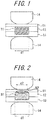
FIG. 1 is a diagram schematically illustrating an example of a nugget formation state in a first step in a resistance spot welding method according to one of the disclosed embodiments; -
FIG. 2 is a diagram schematically illustrating an example of a nugget formation state in a second step in the resistance spot welding method according to one of the disclosed embodiments; -
FIG. 3 is a diagram schematically illustrating an example of the nugget formation state in the second step in the resistance spot welding method according to one of the disclosed embodiments; and -
FIG. 4 is a diagram schematically illustrating the case of welding a sheet combination having a sheet gap in Examples. - Detailed description is given below.
- The disclosure relates to a resistance spot welding method including performing actual welding to squeeze, by a pair of electrodes, a sheet combination in which a thin sheet is overlapped on at least one face of two or more overlapping thick sheets, and passing a current while applying an electrode force to join the sheet combination. The disclosure is particularly intended for a sheet combination whose sheet thickness ratio ((the total thickness of the sheet combination)/(the sheet thickness of the thinnest steel sheet (metal sheet) in the sheet combination)) is more than 3 or further 5 or more, for which it has been difficult to obtain a nugget of a required size between the thin and thick sheets without splashing. The upper limit of the sheet thickness ratio is not particularly limited, but is typically 12.
- Any welding device that includes a pair of upper and lower electrodes and is capable of freely controlling each of the electrode force and the welding current during welding may be used in the resistance spot welding method according to the disclosure. The force mechanism (air cylinder, servomotor, etc.), the type (stationary, robot gun, etc.), the electrode shape, and the like are not particularly limited.
- In the disclosure, the term "thin sheet" means a steel sheet with relatively small sheet thickness and the term "thick sheet" means a steel sheet with relatively large sheet thickness, of the steel sheets used in the sheet combination. Typically, the sheet thickness of the thin sheet is not more than 3/4 of that of the steel sheet (thick sheet) with the largest sheet thickness.
- In the actual welding in the resistance spot welding method according to the disclosure, the current/electrode force pattern is divided into two or more steps to perform welding.
- The following describes the resistance spot welding method according to the disclosure, using an example where a sheet combination in which two steel sheets (thick sheets) 12 and 13 are overlapped on each other and further a
thin sheet 11 is overlapped on one face of thethick sheets FIG. 1 is subjected to resistance spot welding by dividing the current/electrode force pattern into two steps. In the drawing,reference sign 14 is an electrode. - In the actual welding, the sheet combination is squeezed by the pair of upper and lower electrodes at a desired welding position, and electrode force application and current passage are started.
- In the welding in the first step, the electrode force and the welding current are set to suppress splashing, and the part between the
thick sheets thick sheets thin sheet 11 and thethick sheet 12. As a result, splashing between thethin sheet 11 and thethick sheet 12 is suppressed in the current passage in the second step onward. - After such welding (current passage) in the first step, the welding in the second step is performed to form a nugget N2 between the thin sheet I1 and the
thick sheet 12 as illustrated inFIG. 2 . Here, it is important to satisfy the relationship
F1 > F2
where F1 (kN) is the electrode force in the first step and F2 (kN) is the electrode force in the second step. - By satisfying this relationship, a weld fusion zone is formed first in the interface between the
thick sheets thin sheet 11 and thethick sheet 12. - Moreover, by setting the electrode force in the second step to be lower than the electrode force in the first step, the contact area between the
thin sheet 11 and thethick sheet 12 and between thethin sheet 11 and theelectrode 14 is reduced from that in the first step to thus increase the current density, with it being possible to facilitate sufficient heat generation to obtain a nugget of an appropriate diameter between thethin sheet 11 and thethick sheet 12 in the second step as illustrated inFIG. 2 . - Preferably, the electrode force F2 satisfies the relationship
0.5tm ≤ F2 ≤ 8tm
where tm (mm) is the sheet thickness of the thinnest steel sheet of the plurality of steel sheets constituting the sheet combination (the sheet thickness of thethin sheet 11 inFIGS. 1 and 2 ). - If the electrode force F2 (kN) is more than 8tm, the contact area expands excessively and the amount of heat generated is reduced, making it difficult to form a nugget of an appropriate diameter between the
thin sheet 11 and thethick sheet 12. If the electrode force F2 (kN) is less than 0.5tm, the contact resistance between theelectrode 14 and thethin sheet 11 is high, which promotes sparks and also promotes splashing between thethin sheet 11 and thethick sheet 12. A more preferable range is 0.6tm ≤ F2 ≤ 7tm. - In the case where the appropriate condition tends to vary due to disturbances such as current shunting or a sheet gap, it is preferable to perform test welding before the aforementioned actual welding. From the sheet thickness of the parts to be welded and the welding time in the test welding, the cumulative amount of heat generated per unit volume with which the parts to be welded can be welded favorably is calculated for each step in the actual welding. Adaptive control welding of adjusting the welding current or voltage so as to generate the calculated amount of heat generated per unit volume and per unit time is then performed in the actual welding.
- The test welding and the adaptive control welding are described below.
- For the test welding, a welding test with the same steel type and thickness as the parts to be welded is performed by constant current control under various conditions in the state where there is no current shunting to an existing weld or sheet gap, to find an optimal condition in the test welding.
- Then, for each step, the time variation of the instantaneous amount of heat generated per unit volume is stored as a time variation curve, and the cumulative amount of heat generated per unit volume is stored. Both the time variation and the cumulative amount are calculated from the electrical property between the electrodes during welding when the test welding is performed under the aforementioned condition.
- The electrical property between the electrodes in the disclosure means the interelectrode resistance or the interelectrode voltage.
- After the test welding, the adaptive control welding is performed in the actual welding.
- In the adaptive control welding, the time variation curve stored in the test welding for each step is used a target. If the time variation of the instantaneous amount of heat generated per unit volume follows the stored time variation curve, the welding is continued without change and completed.
- If the time variation of the instantaneous amount of heat generated per unit volume differs from the stored time variation curve, on the other hand, the adaptive control welding of controlling the current passage amount is carried out to compensate for the difference within the remaining welding time of the step so that the cumulative amount of heat generated per unit volume in the actual welding matches the stored cumulative amount of heat generated per unit volume. Thus, the required cumulative amount of heat generated can be ensured to obtain an appropriate nugget diameter even in the state where the effects of disturbances such as current shunting or a sheet gap are significant.
- In the disclosure, the method of calculating the amount of heat generated per unit volume is not particularly limited.
JP H11-33743 A - Let t be the total thickness of the parts to be welded, r be the electrical resistivity of the parts to be welded, V be the interelectrode voltage, I be the welding current, and S be the contact area of the electrodes and the parts to be welded. In this case, the welding current passes through a columnar portion whose cross-sectional area is S and thickness is t, to generate heat by resistance. The amount q of heat generated per unit volume and per unit time in the columnar portion is given by the following Equation (1):

- The electrical resistance R of the columnar portion is given by the following Equation (2):

- Solving Equation (2) for S and substituting the solution into Equation (1) yields the amount q of heat generated as shown by the following Equation (3):

- As is clear from Equation (3), the amount q of heat generated per unit volume and per unit time can be calculated from the interelectrode voltage V, the total thickness t of the parts to be welded, and the electrical resistivity r of the parts to be welded, and is not affected by the contact area S of the electrodes and the parts to be welded. Although the amount of heat generated is calculated from the interelectrode voltage V in Equation (3), the amount q of heat generated may be calculated from the interelectrode current I. The contact area S of the electrodes and the parts to be welded need not be used in this case, either. By cumulating the amount q of heat generated per unit volume and per unit time for the welding time, the cumulative amount Q of heat generated per unit volume for the welding is obtained. As is clear from Equation (3), the cumulative amount Q of heat generated per unit volume can also be calculated without using the contact area S of the electrodes and the parts to be welded.
- Although the above describes the case of calculating the cumulative amount Q of heat generated by the method described in PTL 4, the cumulative amount Q may be calculated by any other method.
- In the case of performing constant current control in the actual welding for a sheet combination with a high sheet thickness ratio or in a work state where the effects of a sheet gap or current shunting are significant, it is preferable to satisfy the relationship
I1 < I2
where I1 is the current in the first step and I2 is the current in the second step in the actual welding. - This facilitates heat generation and melting between the thin sheet I1 and the thick sheet I2 in the second step more actively.
- In the case of performing the aforementioned adaptive control welding, it is preferable to satisfy the relationship
I1' < I2'
where I1' is the current in the first step and I2' is the current in the second step in the test welding. - In the case where splashing is highly likely to occur in the second step in such a sheet combination or work state for which the appropriate condition is limited, a cooling time (hereafter also denoted by Tc) is preferably provided between the current passage in the first step and the current passage in the second step in the actual welding.
- By decreasing the temperature after melting the part between the
thick sheets thick sheets - The cooling time is more than 5 cycles (hereafter all time units are expressed by the number of cycles at 50 Hz).
- As mentioned earlier, heat generation and melting between the
thin sheet 11 and thethick sheet 12 in the second step is facilitated by the increase in current density between thethin sheet 11 and thethick sheet 12. In detail, by setting the electrode force F2 (kN) in the second step to be lower than the electrode force F1 (kN) in the first step, the current density between thethin sheet 11 and thethick sheet 12 increases in the second step, thus facilitating heat generation and melting between thethin sheet 11 and thethick sheet 12. - Here, if the cooling time is less than 5 cycles, the current passage in the second step starts in the state where the temperature between the
thick sheets thin sheet 11 and thethick sheet 12 is increased by setting the electrode force F2 (kN) in the second step to be lower than the electrode force F1 (kN) in the first step. This not only makes it impossible to obtain a desired nugget diameter between thethin sheet 11 and thethick sheet 12, but also incites splashing between thethick sheets thin sheet 11 and thethick sheet 12 can be facilitated while preventing excessive nugget growth between thethick sheets - If the cooling time is more than 100 cycles, not only the work time increases excessively, but also the heat generation efficiency between the
thin sheet 11 and thethick sheet 12 to be molten in the second step decreases. Accordingly, the upper limit of the cooling time is preferably 100 cycles. - Preferable welding times T1 and T2 in the first and second steps in the actual welding are typically about 5 cycles to 50 cycles and about I cycle to 20 cycles, respectively.
- The steel sheets to be welded by the resistance spot welding method according to the disclosure are not particularly limited. The resistance spot welding method may be used for the welding of steel sheets and coated steel sheets having various strengths from mild steel to ultra high tensile strength steel and light metal sheets of aluminum alloys and the like. The resistance spot welding method may also be used for a sheet combination of four or more metal sheets in which thin sheets are overlapped on both faces of two or more overlapping thick sheets.
- Current passage in a third step onward may be performed to heat-treat the weld after the current passage in the first and second steps for nugget formation.
- In the first step, the part between the thin sheet I1 and the thick sheet I2 may be partly molten as long as splashing does not occur. In the second step, the part between the thin sheet I1 and the thick sheet I2 may be molten uniformly as illustrated in
FIG. 2 , or only the outer peripheral part may be molten in the shape of a ring while the center part remains not molten as illustrated inFIG. 3 . -
JP 2008-290099 A - Thus, with the welding method in PTL 5, the electrode in contact with the thin sheet is used as the fixed electrode and the electrode in contact with the thick sheet as the movable electrode, and the phenomenon resulting from this arrangement is utilized to perform initial welding with a low electrode force and a high current and subsequent welding with a high electrode force, to form a nugget of an appropriate diameter between the thin and thick sheets and between the thick sheets. With the welding method according to the disclosure, on the other hand, in the case of welding a sheet combination in which a thin sheet is overlapped only on one face of overlapping thick sheets, the electrode in contact with the thin sheet is used as the movable electrode and the electrode in contact with the thick sheet as the fixed electrode according to a conventional method. The welding method according to the disclosure is therefore different from the welding method in PTL 5.
- For each sheet combination of three steel sheets shown in Table 1 and
FIGS. 1 to 4 , resistance spot welding was performed under each condition shown in Table 2 to produce a joint. - The result in the case where the control mode is "constant current" in Table 2 indicates the result of performing welding by constant current control under the welding condition shown in Table 2. The result in the case where the control mode is "adaptive control" in Table 2 indicates the result of, after performing test welding in the absence of disturbances such as a sheet gap under the welding condition in Table 2 and storing the time variation of the instantaneous amount of heat generated per unit volume, performing adaptive control welding of adjusting the current with reference to the time variation curve of the instantaneous amount of heat generated per unit volume obtained in the test welding.
- Upon producing some of the joints, spacers I5 (inter-spacer distance: 60 mm) were inserted between the thick sheets I2 and I3 as illustrated in
FIG. 4 , and the sheet combination was clamped from above and below (not illustrated), to create a sheet gap of any of various sheet gap thicknesses. - An inverter DC resistance spot welder was used as the welder, and chromium copper electrodes with 6 mm face diameter DR-shaped tips were used as the electrodes. The electrode in contact with the thin sheet was the movable electrode, and the electrode in contact with the thick sheet was the fixed electrode.
- For each obtained joint, the weld was cut and etched in section, and then observed with an optical microscope to measure each of the nugget diameter d1 between the thick sheets and the nugget diameter d2 (mm) between the thin and thick sheets. Each sample in which the nugget diameters d1 and d2 were both 4√t' or more (t': the sheet thickness (mm) of the thinner steel sheet of the adjacent two steel sheets) and no splashing occurred was evaluated as good. Each sample in which any of the nugget diameters d1 and d2 was less than 4√t' or splashing occurred was evaluated as poor.
-

-

- In all Examples, no splashing occurred, and a nugget with a diameter of 4√t' or more was obtained between the thick sheets and between the thin and thick sheets.
- In all Comparative Examples outside the range according to the disclosure, on the other hand, either splashing occurred or a sufficient nugget was not formed.
-
- 11
- steel sheet (thin sheet)
- 12, 13
- steel sheet (thick sheet)
- 14
- electrode
- 15
- spacer
Claims (4)
- A resistance spot welding method comprising
performing actual welding to squeeze, by a pair of electrodes, a sheet combination with a sheet thickness ratio of more than 3 in which a thin sheet is overlapped on at least one face of two or more overlapping thick sheets, and passing a current while applying an electrode force to join the sheet combination,
wherein in the actual welding, a pattern of the current and the electrode force is divided into two or more steps including a first step and a second step to perform welding, and an electrode force F1 in the first step and an electrode force F2 in the second step satisfy a relationship
F1 > F2, and
characterized in that a cooling time between current passage in the first step and current passage in the second step in the actual welding is more than 5 cycles and time units are expressed by the number of cycles at 50 Hz. - The resistance spot welding method according to claim 1, further comprising, before the actual welding,
performing test welding and storing, for each of the steps, an amount of time variation of an instantaneous amount of heat generated per unit volume as a time variation curve and storing a cumulative amount of heat generated per unit volume, wherein both the amount of time variation and the cumulative amount of heat being calculated from an electrical property between the electrodes in order to form an appropriate nugget by passing a current by constant current control,
wherein in the actual welding, the stored time variation curve is used as a target and, in the case where a time variation of the instantaneous amount of heat generated per unit volume in the actual welding differs from the stored time variation curve in any of the steps, adaptive control welding is performed to control a current passage amount in order to compensate for the difference within a remaining welding time in the step so that a cumulative amount of heat generated per unit volume in the actual welding matches the stored cumulative amount of heat generated per unit volume. - The resistance spot welding method according to claim 1,
wherein a current I1 in the first step and a current I2 in the second step in the actual welding satisfy a relationship
I1 < I2. - The resistance spot welding method according to claim 2,
wherein a current I1' in the first step and a current I2' in the second step in the test welding satisfy a relationship
I1' < I2'.
Applications Claiming Priority (2)
| Application Number | Priority Date | Filing Date | Title |
|---|---|---|---|
| JP2014243340 | 2014-12-01 | ||
| PCT/JP2015/005771 WO2016088319A1 (en) | 2014-12-01 | 2015-11-18 | Resistance spot welding method |
Publications (3)
| Publication Number | Publication Date |
|---|---|
| EP3228414A1 EP3228414A1 (en) | 2017-10-11 |
| EP3228414A4 EP3228414A4 (en) | 2017-12-13 |
| EP3228414B1 true EP3228414B1 (en) | 2020-08-05 |
Family
ID=56091285
Family Applications (1)
| Application Number | Title | Priority Date | Filing Date |
|---|---|---|---|
| EP15865842.7A Active EP3228414B1 (en) | 2014-12-01 | 2015-11-18 | Resistance spot welding method |
Country Status (7)
| Country | Link |
|---|---|
| US (1) | US10625365B2 (en) |
| EP (1) | EP3228414B1 (en) |
| JP (1) | JP6108030B2 (en) |
| KR (1) | KR101906084B1 (en) |
| CN (1) | CN107000109B (en) |
| MX (1) | MX2017007020A (en) |
| WO (1) | WO2016088319A1 (en) |
Families Citing this family (20)
| Publication number | Priority date | Publication date | Assignee | Title |
|---|---|---|---|---|
| US10625368B2 (en) | 2015-03-16 | 2020-04-21 | Jfe Steel Corporation | Resistance spot welding method and method for manufacturing resistance spot welded joint |
| CN110475642B (en) * | 2017-03-31 | 2021-09-28 | 杰富意钢铁株式会社 | Method for manufacturing resistance spot-welded joint |
| WO2019124467A1 (en) * | 2017-12-19 | 2019-06-27 | 日本製鉄株式会社 | Method for manufacturing resistance spot welded joint |
| WO2019124465A1 (en) * | 2017-12-19 | 2019-06-27 | 日本製鉄株式会社 | Method for manufacturing resistance spot welded joint |
| KR102010069B1 (en) * | 2017-12-22 | 2019-08-12 | 주식회사 포스코 | Method for resistance spot welding of multy-layer steel sheet |
| CN110277204B (en) * | 2018-03-14 | 2021-12-10 | 国巨电子(中国)有限公司 | Shunt resistor and method for manufacturing the same |
| JP7038193B2 (en) * | 2018-03-23 | 2022-03-17 | 本田技研工業株式会社 | Spot welding method |
| CN110364318B (en) * | 2018-03-26 | 2021-08-17 | 国巨电子(中国)有限公司 | High-frequency resistor and method for manufacturing high-frequency resistor |
| US20190358733A1 (en) * | 2018-05-22 | 2019-11-28 | GM Global Technology Operations LLC | Overlapping spot welds for improved mechanical performance and weld repair |
| JP6658992B1 (en) * | 2018-06-29 | 2020-03-04 | Jfeスチール株式会社 | Resistance spot welding method and method for manufacturing welded member |
| US20200055139A1 (en) * | 2018-08-14 | 2020-02-20 | GM Global Technology Operations LLC | Manufacturing method for welding a multi-sheet assembly |
| CN109202245B (en) * | 2018-09-17 | 2021-06-22 | 武汉钢铁有限公司 | Resistance spot welding method suitable for three-layer plate with aluminum-silicon coating as intermediate layer for hot forming steel |
| JP7297788B2 (en) * | 2018-11-26 | 2023-06-26 | 本田技研工業株式会社 | spot welding method |
| JP6790050B2 (en) * | 2018-12-13 | 2020-11-25 | 本田技研工業株式会社 | Resistance welding evaluation device and resistance welding evaluation method |
| US20220288718A1 (en) * | 2019-08-20 | 2022-09-15 | Honda Motor Co., Ltd. | Spot welding method |
| JP6856181B1 (en) * | 2019-08-29 | 2021-04-07 | Jfeスチール株式会社 | Resistance spot welding method and welding member manufacturing method |
| CN111014923A (en) * | 2020-02-18 | 2020-04-17 | 吉林大学 | Resistance spot welding device and method for unequal-thickness plates |
| CN111390366A (en) * | 2020-04-15 | 2020-07-10 | 深圳市欧帝克科技有限公司 | Temperature compensation method for resistance welding electrode |
| US11167378B1 (en) | 2020-05-01 | 2021-11-09 | David W. Steinmeier | Techniques for determining weld quality |
| CN115156681A (en) * | 2022-07-14 | 2022-10-11 | 首钢集团有限公司 | Resistance spot welding method for multilayer board |
Family Cites Families (35)
| Publication number | Priority date | Publication date | Assignee | Title |
|---|---|---|---|---|
| US4135076A (en) * | 1977-04-11 | 1979-01-16 | Beneteau Donald J | Apparatus for resistance welding |
| JPS57202988A (en) * | 1981-06-10 | 1982-12-13 | Nippon Abionikusu Kk | Accommodation controlling device for resistance welding |
| JP2510377B2 (en) * | 1992-05-01 | 1996-06-26 | 株式会社ナ・デックス | Welding controller |
| JP3114440B2 (en) * | 1993-07-22 | 2000-12-04 | 日産自動車株式会社 | Spot welding equipment |
| JPH1058157A (en) * | 1996-06-13 | 1998-03-03 | Kawasaki Heavy Ind Ltd | Method and device for spot welding |
| JP3886603B2 (en) | 1997-07-14 | 2007-02-28 | 株式会社ナ・デックス | Resistance welding system using cumulative heat generation per unit volume as an index |
| DE19917896B4 (en) * | 1998-04-20 | 2019-02-21 | Nissan Motor Co., Ltd. | Spot welding method |
| JP5133490B2 (en) * | 2000-09-21 | 2013-01-30 | マサチューセッツ インスティテュート オブ テクノロジー | Spot welding apparatus and method for detecting welding conditions in real time |
| JP3794300B2 (en) | 2001-08-30 | 2006-07-05 | トヨタ車体株式会社 | Spot welding method |
| JP3894545B2 (en) | 2002-03-05 | 2007-03-22 | 本田技研工業株式会社 | Spot welding method |
| JP4327508B2 (en) | 2003-06-04 | 2009-09-09 | ダイハツ工業株式会社 | Spot welding method and spot welding apparatus |
| US7060929B2 (en) * | 2004-02-24 | 2006-06-13 | General Motors Corporation | Sheet-to-tube resistance spot welding using servo gun |
| FR2895925B1 (en) * | 2006-01-06 | 2008-02-15 | Alcan Technology & Man | METHOD FOR POINT RESISTANCE WELDING OF ALUMINUM ALLOYS |
| JP5261984B2 (en) | 2007-05-23 | 2013-08-14 | Jfeスチール株式会社 | Resistance spot welding method |
| JP5427074B2 (en) * | 2009-03-31 | 2014-02-26 | 本田技研工業株式会社 | Resistance welding method and apparatus |
| WO2011025015A1 (en) * | 2009-08-31 | 2011-03-03 | 新日本製鐵株式会社 | Spot-welded joint and spot welding method |
| JP5468350B2 (en) * | 2009-10-23 | 2014-04-09 | マツダ株式会社 | Dissimilar metal plate joining method |
| JP2011152574A (en) * | 2010-01-28 | 2011-08-11 | Honda Motor Co Ltd | Resistance welding method |
| JP5149355B2 (en) * | 2010-09-08 | 2013-02-20 | 富士重工業株式会社 | Spot welding method and spot welding apparatus |
| JPWO2012050108A1 (en) * | 2010-10-14 | 2014-02-24 | 新日鐵住金株式会社 | Weld quality discrimination device |
| JP5758667B2 (en) | 2011-03-24 | 2015-08-05 | 富士重工業株式会社 | Spot welding equipment |
| US9969026B2 (en) * | 2011-08-25 | 2018-05-15 | GM Global Technology Operations LLC | Weld schedule for resistance spot welding of aluminum alloy workpieces |
| JP5498463B2 (en) * | 2011-10-13 | 2014-05-21 | 富士重工業株式会社 | Pressure control method for spot welding equipment |
| JP5333560B2 (en) * | 2011-10-18 | 2013-11-06 | Jfeスチール株式会社 | Resistance spot welding method and resistance spot welding joint of high strength steel plate |
| JP5267640B2 (en) * | 2011-11-25 | 2013-08-21 | Jfeスチール株式会社 | Evaluation method for resistance spot welded joints |
| IN2015DN00600A (en) | 2012-09-24 | 2015-06-26 | Nippon Steel & Sumitomo Metal Corp | |
| CN103111741A (en) | 2012-12-21 | 2013-05-22 | 上海交通大学 | Controllable electrode force method for lowering welding spatter of resistance spot welding of sandwich plate |
| JP5920523B2 (en) * | 2013-03-08 | 2016-05-18 | Jfeスチール株式会社 | Resistance spot welding method |
| KR101584495B1 (en) * | 2013-03-29 | 2016-01-13 | 제이에프이 스틸 가부시키가이샤 | Resistance spot welding system |
| JP2014200797A (en) | 2013-04-01 | 2014-10-27 | トヨタ自動車株式会社 | Resistance spot welding method and device |
| MX2015015832A (en) * | 2013-06-05 | 2016-03-04 | Nippon Steel & Sumitomo Metal Corp | Spot welded joint and spot welding method. |
| DE102013014701A1 (en) * | 2013-09-05 | 2015-03-05 | GM Global Technology Operations LLC (n. d. Ges. d. Staates Delaware) | Welding assembly for welding a connection portion and method for welding the connection portion to the welding assembly |
| CN106255566B (en) * | 2014-05-07 | 2018-12-18 | 新日铁住金株式会社 | Spot welding method |
| US10279418B2 (en) * | 2014-07-16 | 2019-05-07 | Honda Motor Co., Ltd. | Method and apparatus for resistive spot welding |
| EP3290146B1 (en) * | 2015-04-27 | 2021-08-18 | JFE Steel Corporation | Resistance spot welding method |
-
2015
- 2015-11-18 CN CN201580065285.XA patent/CN107000109B/en active Active
- 2015-11-18 EP EP15865842.7A patent/EP3228414B1/en active Active
- 2015-11-18 KR KR1020177015146A patent/KR101906084B1/en active IP Right Grant
- 2015-11-18 US US15/526,125 patent/US10625365B2/en active Active
- 2015-11-18 JP JP2016513172A patent/JP6108030B2/en active Active
- 2015-11-18 MX MX2017007020A patent/MX2017007020A/en active IP Right Grant
- 2015-11-18 WO PCT/JP2015/005771 patent/WO2016088319A1/en active Application Filing
Non-Patent Citations (1)
| Title |
|---|
| None * |
Also Published As
| Publication number | Publication date |
|---|---|
| JP6108030B2 (en) | 2017-04-05 |
| JPWO2016088319A1 (en) | 2017-04-27 |
| CN107000109B (en) | 2021-09-10 |
| EP3228414A1 (en) | 2017-10-11 |
| MX2017007020A (en) | 2017-08-14 |
| WO2016088319A1 (en) | 2016-06-09 |
| US20170312846A1 (en) | 2017-11-02 |
| EP3228414A4 (en) | 2017-12-13 |
| KR101906084B1 (en) | 2018-10-08 |
| KR20170072948A (en) | 2017-06-27 |
| US10625365B2 (en) | 2020-04-21 |
| CN107000109A (en) | 2017-08-01 |
Similar Documents
| Publication | Publication Date | Title |
|---|---|---|
| EP3228414B1 (en) | Resistance spot welding method | |
| US10625368B2 (en) | Resistance spot welding method and method for manufacturing resistance spot welded joint | |
| EP3391988B1 (en) | Resistance spot welding methods and method of manufacturing welded member using such method | |
| EP3290146B1 (en) | Resistance spot welding method | |
| US11065712B2 (en) | Resistance spot welding method | |
| JP5045238B2 (en) | Resistance spot welding method | |
| EP3342524B1 (en) | Resistance spot welding method and method for manufacturing welded member | |
| JP7115223B2 (en) | Method for manufacturing resistance spot welded joints | |
| KR102622518B1 (en) | Resistance spot welding method and weld member production method | |
| JP6904479B2 (en) | Resistance spot welding method and welding member manufacturing method | |
| JP5082249B2 (en) | Resistance spot welding method | |
| US20230124228A1 (en) | Resistance spot welding method and weld member production method | |
| EP4023384A1 (en) | Resistance spot welding method and method for manufacturing welded member | |
| KR20180011320A (en) | Resistance spot welding method | |
| JP6811063B2 (en) | Resistance spot welding method and resistance spot welding joint manufacturing method |
Legal Events
| Date | Code | Title | Description |
|---|---|---|---|
| STAA | Information on the status of an ep patent application or granted ep patent |
Free format text: STATUS: THE INTERNATIONAL PUBLICATION HAS BEEN MADE |
|
| PUAI | Public reference made under article 153(3) epc to a published international application that has entered the european phase |
Free format text: ORIGINAL CODE: 0009012 |
|
| STAA | Information on the status of an ep patent application or granted ep patent |
Free format text: STATUS: REQUEST FOR EXAMINATION WAS MADE |
|
| 17P | Request for examination filed |
Effective date: 20170516 |
|
| AK | Designated contracting states |
Kind code of ref document: A1 Designated state(s): AL AT BE BG CH CY CZ DE DK EE ES FI FR GB GR HR HU IE IS IT LI LT LU LV MC MK MT NL NO PL PT RO RS SE SI SK SM TR |
|
| AX | Request for extension of the european patent |
Extension state: BA ME |
|
| A4 | Supplementary search report drawn up and despatched |
Effective date: 20171115 |
|
| RIC1 | Information provided on ipc code assigned before grant |
Ipc: B23K 11/16 20060101ALI20171109BHEP Ipc: B23K 11/24 20060101ALI20171109BHEP Ipc: B23K 11/20 20060101AFI20171109BHEP Ipc: B23K 11/11 20060101ALI20171109BHEP |
|
| DAV | Request for validation of the european patent (deleted) | ||
| DAX | Request for extension of the european patent (deleted) | ||
| GRAP | Despatch of communication of intention to grant a patent |
Free format text: ORIGINAL CODE: EPIDOSNIGR1 |
|
| STAA | Information on the status of an ep patent application or granted ep patent |
Free format text: STATUS: GRANT OF PATENT IS INTENDED |
|
| INTG | Intention to grant announced |
Effective date: 20200311 |
|
| GRAS | Grant fee paid |
Free format text: ORIGINAL CODE: EPIDOSNIGR3 |
|
| GRAA | (expected) grant |
Free format text: ORIGINAL CODE: 0009210 |
|
| STAA | Information on the status of an ep patent application or granted ep patent |
Free format text: STATUS: THE PATENT HAS BEEN GRANTED |
|
| AK | Designated contracting states |
Kind code of ref document: B1 Designated state(s): AL AT BE BG CH CY CZ DE DK EE ES FI FR GB GR HR HU IE IS IT LI LT LU LV MC MK MT NL NO PL PT RO RS SE SI SK SM TR |
|
| REG | Reference to a national code |
Ref country code: GB Ref legal event code: FG4D |
|
| REG | Reference to a national code |
Ref country code: CH Ref legal event code: EP |
|
| REG | Reference to a national code |
Ref country code: AT Ref legal event code: REF Ref document number: 1298024 Country of ref document: AT Kind code of ref document: T Effective date: 20200815 |
|
| REG | Reference to a national code |
Ref country code: DE Ref legal event code: R096 Ref document number: 602015057162 Country of ref document: DE |
|
| REG | Reference to a national code |
Ref country code: IE Ref legal event code: FG4D |
|
| REG | Reference to a national code |
Ref country code: LT Ref legal event code: MG4D |
|
| REG | Reference to a national code |
Ref country code: NL Ref legal event code: MP Effective date: 20200805 |
|
| REG | Reference to a national code |
Ref country code: AT Ref legal event code: MK05 Ref document number: 1298024 Country of ref document: AT Kind code of ref document: T Effective date: 20200805 |
|
| PG25 | Lapsed in a contracting state [announced via postgrant information from national office to epo] |
Ref country code: LT Free format text: LAPSE BECAUSE OF FAILURE TO SUBMIT A TRANSLATION OF THE DESCRIPTION OR TO PAY THE FEE WITHIN THE PRESCRIBED TIME-LIMIT Effective date: 20200805 Ref country code: ES Free format text: LAPSE BECAUSE OF FAILURE TO SUBMIT A TRANSLATION OF THE DESCRIPTION OR TO PAY THE FEE WITHIN THE PRESCRIBED TIME-LIMIT Effective date: 20200805 Ref country code: BG Free format text: LAPSE BECAUSE OF FAILURE TO SUBMIT A TRANSLATION OF THE DESCRIPTION OR TO PAY THE FEE WITHIN THE PRESCRIBED TIME-LIMIT Effective date: 20201105 Ref country code: NO Free format text: LAPSE BECAUSE OF FAILURE TO SUBMIT A TRANSLATION OF THE DESCRIPTION OR TO PAY THE FEE WITHIN THE PRESCRIBED TIME-LIMIT Effective date: 20201105 Ref country code: SE Free format text: LAPSE BECAUSE OF FAILURE TO SUBMIT A TRANSLATION OF THE DESCRIPTION OR TO PAY THE FEE WITHIN THE PRESCRIBED TIME-LIMIT Effective date: 20200805 Ref country code: GR Free format text: LAPSE BECAUSE OF FAILURE TO SUBMIT A TRANSLATION OF THE DESCRIPTION OR TO PAY THE FEE WITHIN THE PRESCRIBED TIME-LIMIT Effective date: 20201106 Ref country code: PT Free format text: LAPSE BECAUSE OF FAILURE TO SUBMIT A TRANSLATION OF THE DESCRIPTION OR TO PAY THE FEE WITHIN THE PRESCRIBED TIME-LIMIT Effective date: 20201207 Ref country code: HR Free format text: LAPSE BECAUSE OF FAILURE TO SUBMIT A TRANSLATION OF THE DESCRIPTION OR TO PAY THE FEE WITHIN THE PRESCRIBED TIME-LIMIT Effective date: 20200805 Ref country code: AT Free format text: LAPSE BECAUSE OF FAILURE TO SUBMIT A TRANSLATION OF THE DESCRIPTION OR TO PAY THE FEE WITHIN THE PRESCRIBED TIME-LIMIT Effective date: 20200805 Ref country code: FI Free format text: LAPSE BECAUSE OF FAILURE TO SUBMIT A TRANSLATION OF THE DESCRIPTION OR TO PAY THE FEE WITHIN THE PRESCRIBED TIME-LIMIT Effective date: 20200805 |
|
| PG25 | Lapsed in a contracting state [announced via postgrant information from national office to epo] |
Ref country code: RS Free format text: LAPSE BECAUSE OF FAILURE TO SUBMIT A TRANSLATION OF THE DESCRIPTION OR TO PAY THE FEE WITHIN THE PRESCRIBED TIME-LIMIT Effective date: 20200805 Ref country code: LV Free format text: LAPSE BECAUSE OF FAILURE TO SUBMIT A TRANSLATION OF THE DESCRIPTION OR TO PAY THE FEE WITHIN THE PRESCRIBED TIME-LIMIT Effective date: 20200805 Ref country code: PL Free format text: LAPSE BECAUSE OF FAILURE TO SUBMIT A TRANSLATION OF THE DESCRIPTION OR TO PAY THE FEE WITHIN THE PRESCRIBED TIME-LIMIT Effective date: 20200805 Ref country code: NL Free format text: LAPSE BECAUSE OF FAILURE TO SUBMIT A TRANSLATION OF THE DESCRIPTION OR TO PAY THE FEE WITHIN THE PRESCRIBED TIME-LIMIT Effective date: 20200805 Ref country code: IS Free format text: LAPSE BECAUSE OF FAILURE TO SUBMIT A TRANSLATION OF THE DESCRIPTION OR TO PAY THE FEE WITHIN THE PRESCRIBED TIME-LIMIT Effective date: 20201205 |
|
| PG25 | Lapsed in a contracting state [announced via postgrant information from national office to epo] |
Ref country code: RO Free format text: LAPSE BECAUSE OF FAILURE TO SUBMIT A TRANSLATION OF THE DESCRIPTION OR TO PAY THE FEE WITHIN THE PRESCRIBED TIME-LIMIT Effective date: 20200805 Ref country code: SM Free format text: LAPSE BECAUSE OF FAILURE TO SUBMIT A TRANSLATION OF THE DESCRIPTION OR TO PAY THE FEE WITHIN THE PRESCRIBED TIME-LIMIT Effective date: 20200805 Ref country code: EE Free format text: LAPSE BECAUSE OF FAILURE TO SUBMIT A TRANSLATION OF THE DESCRIPTION OR TO PAY THE FEE WITHIN THE PRESCRIBED TIME-LIMIT Effective date: 20200805 Ref country code: DK Free format text: LAPSE BECAUSE OF FAILURE TO SUBMIT A TRANSLATION OF THE DESCRIPTION OR TO PAY THE FEE WITHIN THE PRESCRIBED TIME-LIMIT Effective date: 20200805 Ref country code: CZ Free format text: LAPSE BECAUSE OF FAILURE TO SUBMIT A TRANSLATION OF THE DESCRIPTION OR TO PAY THE FEE WITHIN THE PRESCRIBED TIME-LIMIT Effective date: 20200805 |
|
| REG | Reference to a national code |
Ref country code: DE Ref legal event code: R097 Ref document number: 602015057162 Country of ref document: DE |
|
| PG25 | Lapsed in a contracting state [announced via postgrant information from national office to epo] |
Ref country code: AL Free format text: LAPSE BECAUSE OF FAILURE TO SUBMIT A TRANSLATION OF THE DESCRIPTION OR TO PAY THE FEE WITHIN THE PRESCRIBED TIME-LIMIT Effective date: 20200805 |
|
| PLBE | No opposition filed within time limit |
Free format text: ORIGINAL CODE: 0009261 |
|
| STAA | Information on the status of an ep patent application or granted ep patent |
Free format text: STATUS: NO OPPOSITION FILED WITHIN TIME LIMIT |
|
| PG25 | Lapsed in a contracting state [announced via postgrant information from national office to epo] |
Ref country code: MC Free format text: LAPSE BECAUSE OF FAILURE TO SUBMIT A TRANSLATION OF THE DESCRIPTION OR TO PAY THE FEE WITHIN THE PRESCRIBED TIME-LIMIT Effective date: 20200805 Ref country code: SK Free format text: LAPSE BECAUSE OF FAILURE TO SUBMIT A TRANSLATION OF THE DESCRIPTION OR TO PAY THE FEE WITHIN THE PRESCRIBED TIME-LIMIT Effective date: 20200805 |
|
| REG | Reference to a national code |
Ref country code: CH Ref legal event code: PL |
|
| 26N | No opposition filed |
Effective date: 20210507 |
|
| PG25 | Lapsed in a contracting state [announced via postgrant information from national office to epo] |
Ref country code: LU Free format text: LAPSE BECAUSE OF NON-PAYMENT OF DUE FEES Effective date: 20201118 Ref country code: IT Free format text: LAPSE BECAUSE OF FAILURE TO SUBMIT A TRANSLATION OF THE DESCRIPTION OR TO PAY THE FEE WITHIN THE PRESCRIBED TIME-LIMIT Effective date: 20200805 |
|
| REG | Reference to a national code |
Ref country code: BE Ref legal event code: MM Effective date: 20201130 |
|
| PG25 | Lapsed in a contracting state [announced via postgrant information from national office to epo] |
Ref country code: LI Free format text: LAPSE BECAUSE OF NON-PAYMENT OF DUE FEES Effective date: 20201130 Ref country code: SI Free format text: LAPSE BECAUSE OF FAILURE TO SUBMIT A TRANSLATION OF THE DESCRIPTION OR TO PAY THE FEE WITHIN THE PRESCRIBED TIME-LIMIT Effective date: 20200805 Ref country code: CH Free format text: LAPSE BECAUSE OF NON-PAYMENT OF DUE FEES Effective date: 20201130 |
|
| PG25 | Lapsed in a contracting state [announced via postgrant information from national office to epo] |
Ref country code: IE Free format text: LAPSE BECAUSE OF NON-PAYMENT OF DUE FEES Effective date: 20201118 |
|
| PG25 | Lapsed in a contracting state [announced via postgrant information from national office to epo] |
Ref country code: TR Free format text: LAPSE BECAUSE OF FAILURE TO SUBMIT A TRANSLATION OF THE DESCRIPTION OR TO PAY THE FEE WITHIN THE PRESCRIBED TIME-LIMIT Effective date: 20200805 Ref country code: MT Free format text: LAPSE BECAUSE OF FAILURE TO SUBMIT A TRANSLATION OF THE DESCRIPTION OR TO PAY THE FEE WITHIN THE PRESCRIBED TIME-LIMIT Effective date: 20200805 Ref country code: CY Free format text: LAPSE BECAUSE OF FAILURE TO SUBMIT A TRANSLATION OF THE DESCRIPTION OR TO PAY THE FEE WITHIN THE PRESCRIBED TIME-LIMIT Effective date: 20200805 |
|
| PG25 | Lapsed in a contracting state [announced via postgrant information from national office to epo] |
Ref country code: MK Free format text: LAPSE BECAUSE OF FAILURE TO SUBMIT A TRANSLATION OF THE DESCRIPTION OR TO PAY THE FEE WITHIN THE PRESCRIBED TIME-LIMIT Effective date: 20200805 |
|
| PG25 | Lapsed in a contracting state [announced via postgrant information from national office to epo] |
Ref country code: BE Free format text: LAPSE BECAUSE OF NON-PAYMENT OF DUE FEES Effective date: 20201130 |
|
| PGFP | Annual fee paid to national office [announced via postgrant information from national office to epo] |
Ref country code: GB Payment date: 20230928 Year of fee payment: 9 |
|
| PGFP | Annual fee paid to national office [announced via postgrant information from national office to epo] |
Ref country code: FR Payment date: 20230929 Year of fee payment: 9 |
|
| PGFP | Annual fee paid to national office [announced via postgrant information from national office to epo] |
Ref country code: DE Payment date: 20230929 Year of fee payment: 9 |