JP3886603B2 - Resistance welding system using cumulative heat generation per unit volume as an index - Google Patents
Resistance welding system using cumulative heat generation per unit volume as an index Download PDFInfo
- Publication number
- JP3886603B2 JP3886603B2 JP18874497A JP18874497A JP3886603B2 JP 3886603 B2 JP3886603 B2 JP 3886603B2 JP 18874497 A JP18874497 A JP 18874497A JP 18874497 A JP18874497 A JP 18874497A JP 3886603 B2 JP3886603 B2 JP 3886603B2
- Authority
- JP
- Japan
- Prior art keywords
- per unit
- unit volume
- welding
- calorific value
- workpiece
- Prior art date
- Legal status (The legal status is an assumption and is not a legal conclusion. Google has not performed a legal analysis and makes no representation as to the accuracy of the status listed.)
- Expired - Lifetime
Links
Images

Classifications
-
- B—PERFORMING OPERATIONS; TRANSPORTING
- B23—MACHINE TOOLS; METAL-WORKING NOT OTHERWISE PROVIDED FOR
- B23K—SOLDERING OR UNSOLDERING; WELDING; CLADDING OR PLATING BY SOLDERING OR WELDING; CUTTING BY APPLYING HEAT LOCALLY, e.g. FLAME CUTTING; WORKING BY LASER BEAM
- B23K11/00—Resistance welding; Severing by resistance heating
- B23K11/24—Electric supply or control circuits therefor
- B23K11/25—Monitoring devices
- B23K11/252—Monitoring devices using digital means
- B23K11/258—Monitoring devices using digital means the measured parameter being a voltage
Description
【0001】
【発明の属する技術分野】
本発明は被溶接物に通電し、その通電によって発生する抵抗発熱を利用して被溶接物を溶接する技術に関する。
【0002】
【従来の技術】
この種の溶接システムは、被溶接物を挟む一対の電極と、その一対の電極間に溶接電流を流す電源装置と、その電源装置を制御する制御装置とを備えている。良好な溶接を実現するためには溶接電力が適正に調整されなければならない。大きすぎれば被溶接物からいわゆるスパッタが飛び散って良好に溶接できず、小さすぎれば充分に加熱されないで溶接不良となる。溶接電流又は溶接電圧を調整することで溶接電力が調整される。
【0003】
溶接電力が過大か過小かを評価するための指標が各種提案されており、最も一般的には、溶接電流を指標とし、検出された電流値が小さすぎば増大させ、大きすぎれば減少させる。
【0004】
【発明が解決しようとする課題】
被溶接物には様々なものがあり、材質やメッキの有無等によって指標の適正値ないし基準値が変化する。例えば、従来一般的である電流値を指標とする場合、同じ電流値であっても、被溶接物の種類によっては、大きすぎたり小さすぎたりする。このために、被溶接物の種類毎に指標に関する基準値を予め実験によって決定しておかなければならない。これは実際の場合、大変な工数を必要とする。
【0005】
更に、一旦、指標に関する基準値を決定しても、溶接の進行と共に基準値を補正していく必要がある。通常、何度も溶接を繰り返しているうちに電極が磨耗する。電極が磨耗してくると、磨耗しない場合の基準値に基づいて制御しても良好な溶接がなされない。磨耗に対応する基準値の補正方法を決定するのにもまた大変な工数が必要とされる。
【0006】
本発明の目的は、被溶接物の種類や電極の磨耗具合によって影響を受けることのない指標を見つけだし、これを指標にすれば、被溶接物の種類や電極の磨耗具合によらないで、同一の基準値を補正することなく使用できるようにすることにある。これが実現できれば、一つの基準を決定するだけで、被溶接物の種類や電極の磨耗具合によらないで常時良好な溶接が実施できるようになる。
【0007】
【課題を解決するための手段】
この発明では、溶接電力を制御する制御装置に、その被溶接物を良好に溶接する単位体積当たりの予め求められた累積発熱量から通電時間を基に単位体積・単位時間当たりの発熱量を計算する。
そして、前記計算された単位体積・単位時間当たりの発熱量を発生させる電極間電圧、又は溶接電流に調整する処理手順を付加した。
【0008】
本発明者が種々の研究をしたところ、単位体積当たりの発熱量(溶接電流通電中の累積発熱量)を指標にして溶接電力を調整すると、被溶接物の種類や電極の磨耗具合にかかわらず、常時安定的に溶接できることを確認した。即ち、単位体積当たりの累積発熱量を様々に変えて実験してみると、それが一定範囲内にあるとき、被溶接物の種類や電極の磨耗具合によらず、安定的に溶接できることが確認された。換言すれば、安定的に良好な溶接結果をもたらす単位体積当たりの累積発熱量は、被溶接物の種類や電極の磨耗具合によって影響を受けないことを見出したのである。
【0009】
また電極の磨耗具合によって電極と被溶接物が接触する面積が変化するので単位体積当たりの発熱量を計算するのが困難であると予想されるところ、実際に計算すると、電極と被溶接物が接触する面積が変化して通電範囲が変化する現象と、それに伴って通電電力も変化する現象が打ち消しあって、電極と被溶接物が接触する面積を考慮しなくとも、単位体積当たりの発熱量が計算できることを見出した。
【0010】
本発明によると、被溶接物の種類や電極の磨耗具合に係わらず、常に良好な溶接を可能とする単位体積当たりの累積発熱量を指標とし、それに基づいて溶接電力が調節されることから、常に良好な溶接が得られる。
この発明の好ましい一態様では、被溶接物の板厚と通電時間とから単位体積当たりの累積発熱量を算出する。多くの場合に、良好な溶接結果をもたらす単位体積当たりの累積発熱量は、板厚と通電時間から算出されることが確認されており、多くの場合にこの方式で良好に溶接される。
【0011】
この発明の好ましい一態様では、時間当たりの発熱量を計算するにあたって、通電時間中の前半で発熱量が高く後半で発熱量が低いパターンに従って通電時間中の単位体積・単位時間当たりの発熱量を計算する。
通電期間中の前半部で発熱量を大きくすると、被溶接物は短時間に昇温され、短時間で溶接できる。通電期間中の後半部で発熱量を小さくすると、被溶接物が過熱されることを防止できる。このために、短時間に必要な累積発熱量を与えることができる。
【0012】
この発明で利用する知見は、溶接が良好に行われた否かを判別する際にも用いることができる。この態様では、被溶接物を挟む一対の電極と、その一対の電極間に溶接電流を流す電源装置と、その電源装置を制御する制御装置とを備えた抵抗溶接システムにおいて、その被溶接物の板厚と通電時間とからその被溶接物を良好に溶接できる単位体積当たりの累積発熱量を算出し、その一方において、通電時間中の単位体積当たりの累積発熱量を計測し、計測された累積発熱量と算出された累積発熱量を比較する手段が付加される。
【0013】
この態様によると、被溶接物の種類や電極の磨耗具合に影響を受けることなく常に安定的な判別が可能となり、溶接不良の判別を簡単に実施して確実に判別することができる。
【0014】
【発明の効果】
この発明によると、単位体積当たりの累積発熱量を基準として溶接電力を制御することで、被溶接物の種類や電極の磨耗具合によらないで常時良好な溶接ができるようになる。また、単位体積当たりの発熱量を基準として判別することで、溶接の適否について常に安定した判別をすることが可能となる。
【0015】
【発明を実施する形態】
この発明による単位体積当たりの発熱量Qの計算の一例を説明する。2枚の被溶接物の合計厚みをtとする。被溶接物の電気抵抗率をrとする。電極間電圧をVとし、溶接電流をIとする。電極と被溶接物が接触する面積をSとする。この場合、溶接電流は横断面積がSで、厚みtの柱状部分を通過して抵抗発熱を発生させる。この柱状部分における単位体積・単位時間当たりの発熱量qは次式で求められる。
【0016】
q=(V・I)/(S・t) (1)
またこの柱状部分の電気抵抗Rは、次式で求められる。
R=(r・t)/S (2)
(2)式をSについて解いてこれを(1)式に代入すると、
q=(V・I・R)/(r・t2)
=(V2)/(r・t2) (3)となる。
【0017】
ここで明らかに、単位体積・単位時間当たりの発熱量qは、電極間電圧Vと被溶接物の合計厚みtと被溶接物の電気抵抗率rから計算でき、電極と被溶接物が接触する面積Sによって影響を受けない。なお、(3)式は電極間電圧Vから発熱量を計算するが、電極間電流Iから発熱量qを計算する事もでき、このときにも電極と被溶接物が接触する面積Sを用いる必要がない。
【0018】
単位体積・単位時間当たりの発熱量qを通電期間中累積すれば、溶接に加えられる単位体積当たりの累積発熱量Qとなる。(3)式から明らかに、この単位体積当たりの発熱量Qもまた電極と被溶接物が接触する面積Sを用いないで算出できる。
本発明では、通電期間期間中に累積される単位体積当たりの発熱量の累積値Qを指標とし、これを基準に溶接電力を調整する。
【0019】
次にこの発明の実施形態の一例を説明する。図1は抵抗溶接システムの全体構成を示し、商用電源10に接続されて使用される。図中26はサイリスタを示し、点弧角を調整することで溶接電流を調整する。サイリスタ26で電流値が調整された溶接電流は溶接トランス30で低電圧大電流に変圧されて一対の電極51,52間に通電される。一対の電極51,52間には被溶接物60が挟持されている。
一対の電極51,52間の挟持圧力は図示しないシリンダで調節される。一対の電極51,52間に挟持される被溶接物60には大電流が通電されて被溶接物自体が抵抗発熱する。この抵抗発熱によって被溶接物60は溶接される。
【0020】
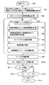
一対の電極51,52間の電圧は電圧計40で測定され、測定値はA/D変換器24で変換された後CPU23に入力される。CPU23はROM21に記憶されている制御プログラムに従って作動し、サイリスタの点弧角を制御して単位時間(この場合サイクル毎)・単位体積当たりの発熱量を調整する。図示25はCPU23から出力される点弧信号によってサイリスタ26を点弧させるインターフェイスである。またRAM22は各種データの一時的記憶に用いられる。ROM21には図2に示される処理手順を実行する制御プログラムが記憶されている。溶接の実行時に図2の処理手順が実行される。
【0021】
まずステップS1で被溶接物の合計板厚tと通電サイクル数cとから、この板厚tの被溶接物を良好に溶接するために必要な単位体積当たりの累積発熱量Qを計算する。被溶接物の種類を変え、板厚を変えて様々に実験してみた結果、良好な溶接をするのに必要な単位体積当たりの累積発熱量Qは、被溶接物の材質、メッキ層の有無やその種類、電極51、52の磨耗具合、電極51、52間の挟圧力の程度によらず、合計板厚tと通電時間(通電サイクル数c)によってのみ決まることが見出された。即ち、良好な溶接結果をもたらす単位体積当たりの累積発熱量Qは次式から求められる。
【0022】
Q=定数(Q0)+係数(k)・通電サイクル数(c)/合計板厚(t)
単位体積当たりの累積発熱量Qを上式に従って求められる値に調整すると、被溶接物の材質、メッキ層の有無やその種類、電極51、52の磨耗具合、電極51、52間の挟圧力の程度によらず、常に安定的に良好な溶接がおこなわれることが確認された。 これは本発明によって確認された事象であり、従来は例えば溶接電流を指標とするなど、単位時間当たりの現象に着目して溶接電力を調整していた。本発明では単位時間当たりの現象でなく、累積発熱量を指標とするために、被溶接物の種類や電極の磨耗具合等に係わらず、常に安定的な溶接が行われるようになった。なお、上記式は適値を求める近似式の一つであり、他の近似式を用いても良い。また、板厚と通電時間で検索されるQのマップを用意しておき、このマップからQの適値を算出するようにしても良い。
【0023】
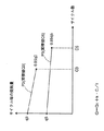
図2のステップS2では、ステップS1で計算された累積発熱量Qを実現するサイクル毎の発熱量qを計算する。図3はサイクル数と各サイクル毎の発熱量の関係を例示している。通電サイクル数は通常板厚に関係し、板厚が薄ければ短時間が指定され、厚ければ長時間が指定される。図中C3は板厚が3mmの場合の通電サイクル数を示し、C5は板厚5mmの場合の通電サイクル数を例示している。図中P3は板厚3mmの場合の累積発熱量Q3を実現するサイクル毎の発熱量を例示している。最初のサイクルではq3の発熱量が加えられ、通電の最後では初期値の85%の発熱量が加えられる。サイクル毎の発熱量をC3回に亘って累積したものがQ3である。図中P5は板厚5mmの場合の累積発熱量Q5を実現するサイクル毎の発熱量を例示している。最初のサイクルではq5の発熱量が加えられ、通電の最後では初期値の85%の発熱量が加えられる。サイクル毎の発熱量をC5回に亘って累積したものがQ5である。
【0024】
各サイクル毎の発熱量qをサイクル数と無関係に一定に維持しても良いが、初期値を大きく取ってその後に徐々に減じていくことが好ましい。この実施例では終値を初期値の85%としている。最初に大発熱させる被溶接物は短時間に加熱されて溶接を短時間で済ませられる。大発熱を維持するとスパッタが出やすいので、徐々に発熱量を低減させる。それでも85%程度は確保する。このような傾向(パターン)に従って、通電中の累積発熱量Qを実現する各サイクル毎の発熱量qを計算すると、良好な溶接が短時間で得られる。
【0025】
図2のステップS3では、通電の終了タイミングか否かを判別する。具体的には通電のサイクル数をカウントし、これが図3で例示したC3ないしC5の終了サイクル数になったか否かを判別する。溶接中はNOであって、ステップS4が実行される。ステップS4では、式(3)を用いて、ステップS2で計算された各サイクル(単位時間)・単位体積当たりの発熱量qをもたらす電極間電圧Vを計算する。このとき、式(3)では単位時間を1秒としており、図3の縦軸ではサイクル毎の発熱量を示しているために、単位時間をそろえて計算する。ステップS5では、ステップS4で計算された電極間電圧Vをもたらす溶接電流Iを計算する。次にその溶接電流値Iを実現する点弧角を計算し、サイリスタ26をその点弧角で点弧して通電する(S6)。通電したら電極間電圧を測定し(S7)、測定された電圧とステップS5で計算した電流値とから電極間抵抗とモニタ用発熱量を計算する(S8)。ステップS7で計算された電極間抵抗は、次回の処理の際にステップS5で電圧Vから電流Iを計算する際に使用される。
【0026】
ステップS4〜S8を各サイクル毎に繰り返し、図3に示したC3ないしC5回が終了すると、ステップS3がYESとなる。この時点以降、ステップS6が実行されず、溶接電流の通電が終了する。溶接電流の通電が終了すると、ステップS9が実行され、ステップS8で計算されたモニタ用発熱量が累積される。
ステップS10以降は溶接結果の判別処理であり、ステップS10では、ステップS9で計算されたモニタ発熱量の累積値をステップS1で計算された指標とする累積発熱量で除する。これが1.0よりもやや低い下限値以上であれば、予定どうりの発熱量が得られており、OK処理をし、溶接が終了する。一致度Xが下限値以下であれば、必要な発熱量が得られなかったため、NG処理をして一体処理を終了する。
【0027】
この実施例では、単位体積当たりの累積発熱量(図3のグラフP3ないしP4を積分したQ3ないしQ5が相当する)を指標として溶接電力を調整するために、被溶接物の種類や溶接電極の磨耗の程度と無関係に基準値を設定することができ、常に安定した溶接を成しえる。
また、各サイクル毎に徐々に発熱量を減らしていくために、溶接の初期に被溶接物が急激に昇温するとともに溶接中の後半で昇温しすぎることを防止でき、短時間に良好に溶接できる。
【0028】
更に、単位体積当たりの累積発熱量を基準に溶接の適否を判別するために、被溶接物の種類や溶接電極の磨耗の程度と無関係に、安定的な判別が可能となる。この実施例の装置を用いたところ、電極の磨耗の程度、メッキ層の有無、被溶接物の材質、電極間の挟圧力、被溶接物間のギャップ、溶接箇所(被溶接物の中心位置か端部か)、隣接する位置に溶接済み箇所があるか否かといった要素と無関係に常に安定的に良好に溶接が行われた。
【図面の簡単な説明】
【図1】1実施例の装置構成を示すブロック図である。
【図2】その実施例で実行する処理手順図である。
【図3】その処理手順によって調整される累積発熱量とサイクル毎の発熱量の一例を示すグラフである。
【主要な符号の説明】
23;CPU
26;サイリスタ
51、51;電極
40;電圧計
S1;被溶接物の板厚と通電時間とからその被溶接物を良好に溶接する単位体積当たりの累積発熱量を計算する処理[0001]
BACKGROUND OF THE INVENTION
The present invention relates to a technique for energizing an object to be welded and welding the object to be welded using resistance heat generated by the energization.
[0002]
[Prior art]
This type of welding system includes a pair of electrodes that sandwich an object to be welded, a power supply device that supplies a welding current between the pair of electrodes, and a control device that controls the power supply device. In order to achieve good welding, the welding power must be properly adjusted. If it is too large, so-called spatter scatters from the work piece and cannot be welded satisfactorily, and if it is too small, it will not be heated sufficiently, resulting in poor welding. The welding power is adjusted by adjusting the welding current or the welding voltage.
[0003]
Various indexes for evaluating whether the welding power is excessive or excessive have been proposed. Most generally, the welding current is used as an index, and the detected current value is increased if it is too small, and it is decreased if it is too large.
[0004]
[Problems to be solved by the invention]
There are various types of workpieces, and the appropriate value or reference value of the index varies depending on the material and the presence or absence of plating. For example, when using a current value that is generally common as an index, even if the current value is the same, it may be too large or too small depending on the type of the workpiece. For this reason, a reference value related to the index must be determined in advance by experiment for each type of workpiece. This actually requires a lot of man-hours.
[0005]
Furthermore, once the reference value for the index is determined, it is necessary to correct the reference value as the welding progresses. Usually, the electrode wears out during repeated welding. When the electrode is worn out, good welding is not performed even if it is controlled based on the reference value when it is not worn. A great amount of man-hours is also required to determine a method for correcting the reference value corresponding to wear.
[0006]
The object of the present invention is to find an index that is not affected by the type of workpiece and electrode wear, and if this is used as an index, it is the same regardless of the type of workpiece and electrode wear. The reference value is to be used without correction. If this can be realized, it is possible to always perform good welding by determining only one criterion, regardless of the type of workpiece and the wear condition of the electrodes.
[0007]
[Means for Solving the Problems]
In this invention, the controller for controlling the welding power calculates the calorific value per unit volume and unit time based on the energization time from the cumulative calorific value per unit volume that is well welded to the workpiece. To do.
And the process procedure which adjusts to the voltage between electrodes which generate | occur | produces the calculated calorific value per unit volume and unit time , or the welding current was added.
[0008]
When the present inventor has made various studies, adjusting the welding power using the calorific value per unit volume (cumulative calorific value during energization of the welding current) as an index, regardless of the type of workpiece and electrode wear It was confirmed that stable welding was possible at all times. In other words, when experimenting with various amounts of accumulated heat generation per unit volume, it was confirmed that when it is within a certain range, stable welding can be performed regardless of the type of workpiece and electrode wear. It was done. In other words, it has been found that the cumulative calorific value per unit volume that produces a stable and good welding result is not affected by the type of work piece and the degree of electrode wear.
[0009]
In addition, it is expected that it is difficult to calculate the calorific value per unit volume because the area where the electrode and the workpiece are in contact changes depending on the degree of wear of the electrode. The phenomenon that the energization range changes due to the change of the contact area and the phenomenon that the energization power changes with it cancels each other out, so even if the area where the electrode and the workpiece are in contact with each other is not considered, the heat generation amount per unit volume Found that can be calculated.
[0010]
According to the present invention, regardless of the type of work piece and the degree of electrode wear, the cumulative heat generation amount per unit volume that always enables good welding is used as an index, and the welding power is adjusted based on that. Good welding is always obtained.
In a preferred aspect of the present invention, the cumulative heat generation amount per unit volume is calculated from the thickness of the work piece and the energization time. In many cases, it has been confirmed that the cumulative calorific value per unit volume that gives good welding results is calculated from the plate thickness and energization time, and in many cases, this method is well welded.
[0011]
In a preferred aspect of the present invention, in calculating the calorific value per hour, the calorific value per unit volume / unit time during the energization time is determined according to a pattern in which the calorific value is high in the first half of the energization time and the calorific value is low in the latter half. calculate.
When the calorific value is increased in the first half during the energization period, the workpiece is heated in a short time and can be welded in a short time. If the heat generation amount is reduced in the latter half of the energization period, the workpiece can be prevented from being overheated. For this reason, it is possible to give the accumulated amount of heat necessary for a short time.
[0012]
The knowledge utilized in this invention can also be used when determining whether or not welding has been performed satisfactorily. In this aspect, in a resistance welding system provided with a pair of electrodes sandwiching a workpiece, a power supply device for passing a welding current between the pair of electrodes, and a control device for controlling the power supply device, Calculate the cumulative calorific value per unit volume that allows the workpiece to be welded well from the plate thickness and energization time, and measure the cumulative calorific value per unit volume during the energization time. A means for comparing the calorific value with the calculated cumulative calorific value is added.
[0013]
According to this aspect, it is possible to always make a stable determination without being affected by the type of the work piece and the degree of wear of the electrode, and it is possible to easily determine the welding failure and make a reliable determination.
[0014]
【The invention's effect】
According to the present invention, by controlling the welding power based on the cumulative calorific value per unit volume, it becomes possible to always perform good welding regardless of the type of the workpiece and the wear condition of the electrodes. Further, by determining based on the heat generation amount per unit volume, it is possible to always perform stable determination as to whether or not welding is appropriate.
[0015]
BEST MODE FOR CARRYING OUT THE INVENTION
An example of the calculation of the calorific value Q per unit volume according to the present invention will be described. Let t be the total thickness of the two workpieces. Let r be the electrical resistivity of the workpiece. The interelectrode voltage is V and the welding current is I. Let S be the area where the electrode and the workpiece are in contact. In this case, the welding current has a cross-sectional area S and passes through a columnar portion having a thickness t to generate resistance heat. The calorific value q per unit volume and unit time in this columnar part is obtained by the following equation.
[0016]
q = (V · I) / (S · t) (1)
Further, the electric resistance R of the columnar portion is obtained by the following equation.
R = (r · t) / S (2)
When (2) is solved for S and this is substituted into (1),
q = (V · I · R) / (r · t 2 )
= (V 2 ) / (r · t 2 ) (3)
[0017]
Obviously, the calorific value q per unit volume / unit time can be calculated from the voltage V between the electrodes, the total thickness t of the workpiece and the electrical resistivity r of the workpiece, and the electrode and the workpiece are in contact with each other. Unaffected by area S. In addition, although the calorific value is calculated from the interelectrode voltage V in the formula (3), the calorific value q can also be calculated from the interelectrode current I. At this time, the area S where the electrode and the workpiece are in contact is used. There is no need.
[0018]
If the calorific value q per unit volume / unit time is accumulated during the energization period, the cumulative calorific value Q per unit volume applied to welding is obtained. As apparent from the equation (3), the calorific value Q per unit volume can also be calculated without using the area S where the electrode and the workpiece are in contact.
In the present invention, the accumulated power Q per unit volume accumulated during the energization period is used as an index, and the welding power is adjusted based on this.
[0019]
Next, an example of an embodiment of the present invention will be described. FIG. 1 shows the overall configuration of a resistance welding system, which is used by being connected to a
The clamping pressure between the pair of
[0020]
The voltage between the pair of
[0021]
First, in step S1, a cumulative heat generation amount Q per unit volume necessary for satisfactorily welding a workpiece having the thickness t is calculated from the total thickness t of the workpiece and the number of energization cycles c. As a result of various experiments by changing the type of workpiece and changing the plate thickness, the cumulative calorific value Q per unit volume required for good welding is the material of the workpiece, whether there is a plating layer It has been found that it is determined only by the total thickness t and the energization time (the number of energization cycles c), regardless of the type, the degree of wear of the
[0022]
Q = constant (Q0) + coefficient (k) / number of energization cycles (c) / total sheet thickness (t)
When the cumulative calorific value Q per unit volume is adjusted to the value obtained according to the above formula, the material of the workpiece, the presence or absence of the plating layer and the type thereof, the wear condition of the
[0023]
In step S2 of FIG. 2, a calorific value q for each cycle that realizes the cumulative calorific value Q calculated in step S1 is calculated. FIG. 3 illustrates the relationship between the number of cycles and the calorific value for each cycle. The number of energization cycles is usually related to the plate thickness. If the plate thickness is thin, a short time is specified, and if it is thick, a long time is specified. In the figure, C3 indicates the number of energization cycles when the plate thickness is 3 mm, and C5 illustrates the number of energization cycles when the plate thickness is 5 mm. P3 in the figure illustrates the heat generation amount for each cycle for realizing the cumulative heat generation amount Q3 when the plate thickness is 3 mm. In the first cycle, a calorific value of q3 is added, and at the end of energization, a calorific value of 85% of the initial value is added. Q3 is the cumulative amount of heat generated every cycle over C3 times. In the figure, P5 exemplifies the calorific value for each cycle for realizing the cumulative calorific value Q5 when the plate thickness is 5 mm. In the first cycle, a calorific value of q5 is added, and at the end of energization, a calorific value of 85% of the initial value is added. Q5 is the cumulative amount of heat generated per cycle over C5 times.
[0024]
Although the calorific value q for each cycle may be kept constant regardless of the number of cycles, it is preferable to take a large initial value and then gradually reduce it. In this embodiment, the closing price is 85% of the initial value. The work to be heated first is heated in a short time, and welding can be completed in a short time. Since spatter is likely to occur if large heat generation is maintained, the heat generation amount is gradually reduced. Still, about 85% is secured. When the calorific value q for each cycle realizing the cumulative calorific value Q during energization is calculated according to such a trend (pattern), good welding can be obtained in a short time.
[0025]
In step S3 of FIG. 2, it is determined whether or not the energization end timing is reached. Specifically, the number of energization cycles is counted, and it is determined whether or not this is the end cycle number of C3 to C5 illustrated in FIG. During welding, it is NO and step S4 is executed. In step S4, the voltage V between electrodes which produces the calorific value q per each cycle (unit time) and unit volume calculated in step S2 is calculated using the equation (3). At this time, in unit (3), the unit time is 1 second, and the vertical axis in FIG. 3 indicates the calorific value for each cycle. In step S5, the welding current I that causes the interelectrode voltage V calculated in step S4 is calculated. Next, the firing angle that realizes the welding current value I is calculated, and the
[0026]
Steps S4 to S8 are repeated for each cycle, and when C3 to C5 times shown in FIG. 3 are completed, step S3 becomes YES. After this point, step S6 is not executed, and the energization of the welding current ends. When energization of the welding current is completed, step S9 is executed, and the heating value for monitoring calculated in step S8 is accumulated.
The process after step S10 is a welding result discrimination process. In step S10, the cumulative value of the monitor heat generation amount calculated in step S9 is divided by the cumulative heat generation amount used as the index calculated in step S1. If this is equal to or lower than the lower limit value slightly lower than 1.0, a planned amount of heat generation is obtained, OK processing is performed, and welding is completed. If the degree of coincidence X is equal to or lower than the lower limit value, the necessary heat generation amount cannot be obtained, so the NG process is performed and the integrated process is terminated.
[0027]
In this embodiment, in order to adjust the welding power using the cumulative heat generation amount per unit volume (corresponding to Q3 to Q5 obtained by integrating the graphs P3 to P4 in FIG. 3) as an index, A reference value can be set regardless of the degree of wear, and stable welding can always be achieved.
In addition, since the calorific value is gradually reduced for each cycle, it is possible to prevent the workpiece from being heated rapidly at the initial stage of welding and preventing the temperature from being raised excessively in the latter half of the welding. Can be welded.
[0028]
Furthermore, in order to determine the suitability of welding based on the accumulated heat generation amount per unit volume, it is possible to perform stable determination regardless of the type of workpiece and the degree of wear of the welding electrode. Using the apparatus of this example, the degree of electrode wear, the presence or absence of a plating layer, the material of the workpiece, the clamping force between the electrodes, the gap between the workpieces, the welding location (the center position of the workpiece) It was always stable and well welded, regardless of whether there was a welded spot at the adjacent position.
[Brief description of the drawings]
FIG. 1 is a block diagram showing an apparatus configuration of one embodiment.
FIG. 2 is a processing procedure diagram executed in the embodiment.
FIG. 3 is a graph showing an example of a cumulative heat generation amount adjusted according to the processing procedure and a heat generation amount for each cycle.
[Description of main symbols]
23; CPU
26; Thyristors 51 and 51;
Claims (3)
その被溶接物を良好に溶接する単位体積当たりの予め求められた累積発熱量から通電時間を基に単位体積・単位時間当たりの発熱量を計算し、
前記計算された単位体積・単位時間当たりの発熱量を発生させる電極間電圧、又は溶接電流に調整する処理手順を付加したことを特徴とする抵抗溶接システム。In a resistance welding system comprising a pair of electrodes sandwiching an object to be welded, a power supply device for passing a welding current between the pair of electrodes, and a control device for controlling the power supply device,
Calculate the calorific value per unit volume and unit time based on the energization time from the cumulative calorific value per unit volume that is well welded to the workpiece,
A resistance welding system, characterized in that a processing procedure for adjusting the calculated inter-electrode voltage for generating a calorific value per unit volume / unit time or a welding current is added.
その被溶接物の板厚と通電時間をパラメータとした近似式から、その被溶接物を良好に溶接する単位体積当たりの累積発熱量を求めることを特徴とする抵抗溶接システム。The resistance welding system according to claim 1,
A resistance welding system characterized in that a cumulative amount of heat generation per unit volume for satisfactorily welding the workpiece is obtained from an approximate expression using the plate thickness and energization time of the workpiece as parameters.
Priority Applications (5)
| Application Number | Priority Date | Filing Date | Title |
|---|---|---|---|
| JP18874497A JP3886603B2 (en) | 1997-07-14 | 1997-07-14 | Resistance welding system using cumulative heat generation per unit volume as an index |
| EP98305423A EP0891836B1 (en) | 1997-07-14 | 1998-07-08 | Electric resistance welding system |
| DE69819420T DE69819420T2 (en) | 1997-07-14 | 1998-07-08 | Electrical resistance welding system |
| ES98305423T ES2209067T3 (en) | 1997-07-14 | 1998-07-08 | WELDING SYSTEM BY ELECTRICAL RESISTANCE. |
| US09/112,054 US6130396A (en) | 1997-07-14 | 1998-07-09 | Electric resistance welding system |
Applications Claiming Priority (1)
| Application Number | Priority Date | Filing Date | Title |
|---|---|---|---|
| JP18874497A JP3886603B2 (en) | 1997-07-14 | 1997-07-14 | Resistance welding system using cumulative heat generation per unit volume as an index |
Publications (2)
| Publication Number | Publication Date |
|---|---|
| JPH1133743A JPH1133743A (en) | 1999-02-09 |
| JP3886603B2 true JP3886603B2 (en) | 2007-02-28 |
Family
ID=16229020
Family Applications (1)
| Application Number | Title | Priority Date | Filing Date |
|---|---|---|---|
| JP18874497A Expired - Lifetime JP3886603B2 (en) | 1997-07-14 | 1997-07-14 | Resistance welding system using cumulative heat generation per unit volume as an index |
Country Status (5)
| Country | Link |
|---|---|
| US (1) | US6130396A (en) |
| EP (1) | EP0891836B1 (en) |
| JP (1) | JP3886603B2 (en) |
| DE (1) | DE69819420T2 (en) |
| ES (1) | ES2209067T3 (en) |
Families Citing this family (31)
| Publication number | Priority date | Publication date | Assignee | Title |
|---|---|---|---|---|
| US6609033B1 (en) | 1999-08-03 | 2003-08-19 | Nadex Co. Ltd | Field programmable welding controller |
| JP2002096178A (en) * | 2000-09-21 | 2002-04-02 | Toyota Auto Body Co Ltd | Spot welding device |
| JP4290448B2 (en) * | 2003-03-20 | 2009-07-08 | 株式会社ダイヘン | Resistance welding control method |
| US7244905B2 (en) * | 2005-06-09 | 2007-07-17 | Daimlerchrysler Corporation | Method for estimating nugget diameter and weld parameters |
| US20070221629A1 (en) * | 2006-03-22 | 2007-09-27 | Vernon Fernandez | Resistance spot welding system and method |
| US20080041827A1 (en) * | 2006-05-26 | 2008-02-21 | Wei Li | Resistance Spot Welding Monitoring System and Method |
| JP4582162B2 (en) * | 2008-03-05 | 2010-11-17 | 株式会社デンソー | Fusing quality control method and apparatus |
| EP2243602B1 (en) * | 2009-04-22 | 2013-05-15 | KUKA Roboter GmbH | Method and device for controlling a manipulator |
| AT507774B1 (en) * | 2009-05-14 | 2010-08-15 | Fronius Int Gmbh | METHOD AND DEVICE FOR DETERMINING THE VOLTAGE ON THE ELECTRODES OF A POINT WELDING TONGUE |
| US9421634B2 (en) | 2011-11-09 | 2016-08-23 | Fca Us Llc | System and method for performing resistance spot welding |
| US10328518B2 (en) | 2013-03-08 | 2019-06-25 | Jfe Steel Corporation | Resistance spot welding method |
| EP2979806B1 (en) | 2013-03-29 | 2017-07-26 | JFE Steel Corporation | Resistance spot welding system |
| JP5582277B1 (en) * | 2013-03-29 | 2014-09-03 | Jfeスチール株式会社 | Resistance spot welding system |
| EP3053693B1 (en) * | 2013-10-04 | 2018-02-21 | JFE Steel Corporation | Resistance spot welding method |
| EP3088119B1 (en) | 2013-12-27 | 2018-07-25 | JFE Steel Corporation | Resistance spot welding method |
| CN106457453B (en) * | 2014-06-12 | 2019-01-08 | 杰富意钢铁株式会社 | Resistance spot welding device and resistance spot welding method |
| EP3228414B1 (en) | 2014-12-01 | 2020-08-05 | JFE Steel Corporation | Resistance spot welding method |
| WO2016147551A1 (en) | 2015-03-16 | 2016-09-22 | Jfeスチール株式会社 | Resistance spot welding method and method for manufacturing resistance spot welded joint |
| KR101974298B1 (en) | 2015-04-27 | 2019-04-30 | 제이에프이 스틸 가부시키가이샤 | Resistance spot welding method |
| US11065712B2 (en) | 2016-06-09 | 2021-07-20 | Jfe Steel Corporation | Resistance spot welding method |
| CN110997210B (en) | 2017-08-18 | 2021-09-28 | 杰富意钢铁株式会社 | Resistance spot welding method and method for manufacturing welded member |
| JP7112819B2 (en) * | 2017-11-29 | 2022-08-04 | ダイハツ工業株式会社 | Spot welding method and spot welding device |
| EP3756814B1 (en) | 2018-02-19 | 2023-11-22 | JFE Steel Corporation | Resistance spot welding method and weld member production method |
| WO2020004115A1 (en) | 2018-06-29 | 2020-01-02 | Jfeスチール株式会社 | Resistance spot welding method and method for manufacturing welded member |
| JP6658993B1 (en) | 2018-06-29 | 2020-03-04 | Jfeスチール株式会社 | Resistance spot welding method and method for manufacturing welded member |
| MX2020013762A (en) | 2018-06-29 | 2021-03-02 | Jfe Steel Corp | Resistance spot welding method and method for manufacturing welded member. |
| WO2020095847A1 (en) * | 2018-11-08 | 2020-05-14 | Jfeスチール株式会社 | Resistance spot welding method and method for manufacturing welded member |
| JP6790050B2 (en) * | 2018-12-13 | 2020-11-25 | 本田技研工業株式会社 | Resistance welding evaluation device and resistance welding evaluation method |
| KR102617967B1 (en) | 2019-08-29 | 2023-12-22 | 제이에프이 스틸 가부시키가이샤 | Resistance spot welding method and weld member production method |
| CN114466722B (en) | 2019-10-09 | 2023-03-28 | 杰富意钢铁株式会社 | Resistance spot welding method and method for manufacturing welded member |
| EP4043141A4 (en) | 2019-10-09 | 2022-12-21 | JFE Steel Corporation | Resistance spot welding method and method for manufacturing welded member |
Family Cites Families (29)
| Publication number | Priority date | Publication date | Assignee | Title |
|---|---|---|---|---|
| US3389239A (en) * | 1964-02-11 | 1968-06-18 | Gen Motors Corp | Method and means for testing welding equipment |
| US4028522A (en) * | 1975-04-29 | 1977-06-07 | Martin Marietta Corporation | Multi-mode structural weld monitor on a time base |
| DE2555792A1 (en) * | 1975-12-11 | 1977-06-23 | Eichhorn Friedrich Prof Dr | PROCEDURE FOR QUALITY ASSURANCE OF THE WELDED JOINTS DURING ELECTRIC RESISTANCE SPOT WELDING |
| US4343980A (en) * | 1980-04-02 | 1982-08-10 | Republic Steel Corporation | Control of welding energy flux density |
| US4302653A (en) * | 1980-04-02 | 1981-11-24 | Weltronic Company | Method and apparatus for monitoring and controlling a resistance welding operation |
| FR2480651B1 (en) * | 1980-04-21 | 1985-09-06 | Nissan Motor | METHOD AND SYSTEM FOR CONTROLLING ELECTRIC RESISTANCE WELDING |
| DE3018384A1 (en) * | 1980-05-14 | 1981-11-19 | Rossell Electronique S.A., Lausanne | METHOD FOR ATTACHING AT LEAST ONE ELECTRODE, FEEDING DEVICE AND RECEIVER FOR CARRYING OUT THIS METHOD, AND USE OF THE METHOD, THE FEEDING DEVICE AND / OR THE RECEIVER |
| US4419560A (en) * | 1980-12-19 | 1983-12-06 | Midland-Ross Corporation | Welding control with automatic percent heat adjustment |
| JPS57146485A (en) * | 1981-03-04 | 1982-09-09 | Sanyo Kiko Kk | Current controlling device for resistance welding |
| US4456810A (en) * | 1982-03-29 | 1984-06-26 | Ford Motor Company | Adaptive schedule selective weld control |
| JPS58181488A (en) * | 1982-04-16 | 1983-10-24 | Sanyo Kiko Kk | Method for controlling resistance welding current |
| US4447700A (en) * | 1982-06-07 | 1984-05-08 | General Electric Company | Resistance spot welder adaptive control |
| US4503311A (en) * | 1983-05-25 | 1985-03-05 | General Motors Corporation | Method and apparatus for detecting the onset of melting in a resistance spot weld |
| US4542277A (en) * | 1984-05-29 | 1985-09-17 | Cecil Dimitrios G | Resistance spot welding gun with weld quality detection feature |
| US4678887A (en) * | 1986-07-09 | 1987-07-07 | General Motors Corporation | Method and apparatus for resistance welding |
| US4694135A (en) * | 1986-07-09 | 1987-09-15 | General Motors Corporation | Method and apparatus for monitoring and controlling resistance spot welding |
| US4792656A (en) * | 1986-09-17 | 1988-12-20 | Miyachi Electronic Company | Invertor type DC resistance welding machine |
| US4711984A (en) * | 1987-03-09 | 1987-12-08 | General Motors Corporation | Ultrasonic method and apparatus for spot weld control |
| US4861960A (en) * | 1988-04-25 | 1989-08-29 | General Electric Company | Real time adaptive control for resistance spot welding process |
| JPH0815669B2 (en) * | 1988-07-06 | 1996-02-21 | 日本電装株式会社 | Control device for resistance welding |
| JPH0284276A (en) * | 1988-09-21 | 1990-03-26 | Dengensha Mfg Co Ltd | Electrode pressure device for resistance welding machine |
| US5081338A (en) * | 1991-02-15 | 1992-01-14 | Unitek Equipment Inc. | Apparatus and method for monitoring weld quality |
| US5111020A (en) * | 1991-05-02 | 1992-05-05 | Ariel Stiebel | Method and apparatus for controlling electrical resistance spot welding |
| US5386092A (en) * | 1991-11-04 | 1995-01-31 | Unitek Equipment Inc. | Fast response weld head |
| JP2510377B2 (en) * | 1992-05-01 | 1996-06-26 | 株式会社ナ・デックス | Welding controller |
| JPH0759351B2 (en) * | 1992-06-10 | 1995-06-28 | 株式会社ナ・デックス | Welding controller |
| DE69321670T2 (en) * | 1992-07-31 | 1999-05-20 | Matsushita Electric Ind Co Ltd | Resistance welding monitor |
| JPH0760457A (en) * | 1993-08-26 | 1995-03-07 | Na Detsukusu:Kk | Resistance welding machine |
| US5483035A (en) * | 1993-09-21 | 1996-01-09 | Nadex Co., Ltd. | System for and method of controlling resistance welder |
-
1997
- 1997-07-14 JP JP18874497A patent/JP3886603B2/en not_active Expired - Lifetime
-
1998
- 1998-07-08 EP EP98305423A patent/EP0891836B1/en not_active Expired - Lifetime
- 1998-07-08 ES ES98305423T patent/ES2209067T3/en not_active Expired - Lifetime
- 1998-07-08 DE DE69819420T patent/DE69819420T2/en not_active Expired - Fee Related
- 1998-07-09 US US09/112,054 patent/US6130396A/en not_active Expired - Lifetime
Also Published As
| Publication number | Publication date |
|---|---|
| ES2209067T3 (en) | 2004-06-16 |
| US6130396A (en) | 2000-10-10 |
| DE69819420D1 (en) | 2003-12-11 |
| JPH1133743A (en) | 1999-02-09 |
| DE69819420T2 (en) | 2004-09-02 |
| EP0891836A2 (en) | 1999-01-20 |
| EP0891836A3 (en) | 1999-08-04 |
| EP0891836B1 (en) | 2003-11-05 |
Similar Documents
| Publication | Publication Date | Title |
|---|---|---|
| JP3886603B2 (en) | Resistance welding system using cumulative heat generation per unit volume as an index | |
| US6506997B2 (en) | Spot welding system and method for sensing welding conditions in real time | |
| US6930279B2 (en) | Electric arc welder and method for controlling the welding process of the welder | |
| EP1413381B1 (en) | Method of operating an electric arc welder | |
| EP0059279A1 (en) | Power factor monitoring and control system for resistance welding | |
| JP3221296B2 (en) | Control device and control method for resistance welding | |
| US4408114A (en) | Resistance welding with pressure control in response to deviation between welding voltage and time varying reference values therefor | |
| US20190076954A1 (en) | Resistance welding method and resistance welding apparatus | |
| JPH09216071A (en) | Control device of resistance welding equipment | |
| JP2825708B2 (en) | Resistance welding control device | |
| JPH0716791B2 (en) | Resistance spot welding method | |
| JP3507843B2 (en) | Resistance welding control method and apparatus | |
| JP2742544B2 (en) | Resistance welding control method and apparatus | |
| JP3221305B2 (en) | Control device of resistance welding machine | |
| JP2584300B2 (en) | Automatic setting device for spot welding conditions | |
| JPH1177328A (en) | Device and method of controlling quality in resistance spot welding | |
| JP4268274B2 (en) | Resistance welding device having a weld temperature region discrimination function | |
| JPH0375610B2 (en) | ||
| JP3163530B2 (en) | Control device for resistance welding | |
| JPS63137586A (en) | Device for controlling resistance welding | |
| RU2301729C2 (en) | Resistance spot welding process control method | |
| JPS607908Y2 (en) | Control device for battery-powered resistance welding machine | |
| JPH0217915B2 (en) | ||
| JP3325333B2 (en) | Energizing method and energizing control device in electrofusion | |
| RU2311273C2 (en) | Heat release at contact spot welding automatic measuring and controlling method |
Legal Events
| Date | Code | Title | Description |
|---|---|---|---|
| A521 | Request for written amendment filed |
Free format text: JAPANESE INTERMEDIATE CODE: A523 Effective date: 20040510 |
|
| A621 | Written request for application examination |
Free format text: JAPANESE INTERMEDIATE CODE: A621 Effective date: 20040510 |
|
| A977 | Report on retrieval |
Free format text: JAPANESE INTERMEDIATE CODE: A971007 Effective date: 20050908 |
|
| A131 | Notification of reasons for refusal |
Free format text: JAPANESE INTERMEDIATE CODE: A131 Effective date: 20050913 |
|
| A521 | Request for written amendment filed |
Free format text: JAPANESE INTERMEDIATE CODE: A523 Effective date: 20051110 |
|
| A131 | Notification of reasons for refusal |
Free format text: JAPANESE INTERMEDIATE CODE: A131 Effective date: 20060228 |
|
| A521 | Request for written amendment filed |
Free format text: JAPANESE INTERMEDIATE CODE: A523 Effective date: 20060404 |
|
| A131 | Notification of reasons for refusal |
Free format text: JAPANESE INTERMEDIATE CODE: A131 Effective date: 20060704 |
|
| RD02 | Notification of acceptance of power of attorney |
Free format text: JAPANESE INTERMEDIATE CODE: A7422 Effective date: 20060712 |
|
| A521 | Request for written amendment filed |
Free format text: JAPANESE INTERMEDIATE CODE: A523 Effective date: 20060724 |
|
| TRDD | Decision of grant or rejection written | ||
| A01 | Written decision to grant a patent or to grant a registration (utility model) |
Free format text: JAPANESE INTERMEDIATE CODE: A01 Effective date: 20061024 |
|
| A61 | First payment of annual fees (during grant procedure) |
Free format text: JAPANESE INTERMEDIATE CODE: A61 Effective date: 20061122 |
|
| R150 | Certificate of patent or registration of utility model |
Free format text: JAPANESE INTERMEDIATE CODE: R150 |
|
| FPAY | Renewal fee payment (event date is renewal date of database) |
Free format text: PAYMENT UNTIL: 20091201 Year of fee payment: 3 |
|
| FPAY | Renewal fee payment (event date is renewal date of database) |
Free format text: PAYMENT UNTIL: 20121201 Year of fee payment: 6 |
|
| FPAY | Renewal fee payment (event date is renewal date of database) |
Free format text: PAYMENT UNTIL: 20121201 Year of fee payment: 6 |
|
| FPAY | Renewal fee payment (event date is renewal date of database) |
Free format text: PAYMENT UNTIL: 20151201 Year of fee payment: 9 |
|
| R250 | Receipt of annual fees |
Free format text: JAPANESE INTERMEDIATE CODE: R250 |
|
| EXPY | Cancellation because of completion of term |