EP3227880B1 - Outil de formation à une injection émettant une lumière omnidirectionnelle - Google Patents
Outil de formation à une injection émettant une lumière omnidirectionnelle Download PDFInfo
- Publication number
- EP3227880B1 EP3227880B1 EP15828554.4A EP15828554A EP3227880B1 EP 3227880 B1 EP3227880 B1 EP 3227880B1 EP 15828554 A EP15828554 A EP 15828554A EP 3227880 B1 EP3227880 B1 EP 3227880B1
- Authority
- EP
- European Patent Office
- Prior art keywords
- light
- needle tip
- testing tool
- needle
- tip
- Prior art date
- Legal status (The legal status is an assumption and is not a legal conclusion. Google has not performed a legal analysis and makes no representation as to the accuracy of the status listed.)
- Active
Links
- 238000002347 injection Methods 0.000 title description 95
- 239000007924 injection Substances 0.000 title description 95
- 238000012549 training Methods 0.000 title description 30
- 239000000463 material Substances 0.000 claims description 53
- 238000012360 testing method Methods 0.000 claims description 45
- 239000013307 optical fiber Substances 0.000 claims description 26
- 239000011521 glass Substances 0.000 claims description 7
- 239000003795 chemical substances by application Substances 0.000 claims description 6
- 230000004044 response Effects 0.000 claims description 6
- 239000011343 solid material Substances 0.000 claims description 5
- GWEVSGVZZGPLCZ-UHFFFAOYSA-N Titan oxide Chemical compound O=[Ti]=O GWEVSGVZZGPLCZ-UHFFFAOYSA-N 0.000 claims description 4
- 239000011344 liquid material Substances 0.000 claims description 3
- 229910052751 metal Inorganic materials 0.000 claims description 2
- 239000002184 metal Substances 0.000 claims description 2
- 239000002245 particle Substances 0.000 claims description 2
- 239000000843 powder Substances 0.000 claims description 2
- 239000004408 titanium dioxide Substances 0.000 claims description 2
- 238000000034 method Methods 0.000 description 29
- 239000007787 solid Substances 0.000 description 11
- 230000001225 therapeutic effect Effects 0.000 description 9
- 239000002537 cosmetic Substances 0.000 description 8
- 239000000945 filler Substances 0.000 description 6
- 230000008569 process Effects 0.000 description 6
- 230000002500 effect on skin Effects 0.000 description 5
- 230000004888 barrier function Effects 0.000 description 4
- 230000008901 benefit Effects 0.000 description 4
- 238000001514 detection method Methods 0.000 description 4
- 239000007788 liquid Substances 0.000 description 4
- 241001465754 Metazoa Species 0.000 description 3
- 230000006378 damage Effects 0.000 description 3
- 210000003128 head Anatomy 0.000 description 3
- 239000002858 neurotransmitter agent Substances 0.000 description 3
- 238000012545 processing Methods 0.000 description 3
- 230000000069 prophylactic effect Effects 0.000 description 3
- 239000000126 substance Substances 0.000 description 3
- 210000001835 viscera Anatomy 0.000 description 3
- 208000002193 Pain Diseases 0.000 description 2
- 108010057266 Type A Botulinum Toxins Proteins 0.000 description 2
- 238000010521 absorption reaction Methods 0.000 description 2
- 238000001467 acupuncture Methods 0.000 description 2
- 210000003484 anatomy Anatomy 0.000 description 2
- 229940089093 botox Drugs 0.000 description 2
- 210000000038 chest Anatomy 0.000 description 2
- 239000011248 coating agent Substances 0.000 description 2
- 238000000576 coating method Methods 0.000 description 2
- 238000009792 diffusion process Methods 0.000 description 2
- 230000001815 facial effect Effects 0.000 description 2
- 229910052500 inorganic mineral Inorganic materials 0.000 description 2
- 230000000670 limiting effect Effects 0.000 description 2
- 238000004519 manufacturing process Methods 0.000 description 2
- 239000011707 mineral Substances 0.000 description 2
- 210000003205 muscle Anatomy 0.000 description 2
- 239000004033 plastic Substances 0.000 description 2
- 238000012797 qualification Methods 0.000 description 2
- 239000010979 ruby Substances 0.000 description 2
- 229910001750 ruby Inorganic materials 0.000 description 2
- 238000002560 therapeutic procedure Methods 0.000 description 2
- 210000001519 tissue Anatomy 0.000 description 2
- 238000011282 treatment Methods 0.000 description 2
- 201000004569 Blindness Diseases 0.000 description 1
- 206010007882 Cellulitis Diseases 0.000 description 1
- 208000000094 Chronic Pain Diseases 0.000 description 1
- 208000034656 Contusions Diseases 0.000 description 1
- 206010018691 Granuloma Diseases 0.000 description 1
- 206010019233 Headaches Diseases 0.000 description 1
- 208000032843 Hemorrhage Diseases 0.000 description 1
- 241000282412 Homo Species 0.000 description 1
- 229920001954 Restylane Polymers 0.000 description 1
- 206010067868 Skin mass Diseases 0.000 description 1
- 206010040893 Skin necrosis Diseases 0.000 description 1
- 206010042674 Swelling Diseases 0.000 description 1
- 208000027418 Wounds and injury Diseases 0.000 description 1
- 108010079650 abobotulinumtoxinA Proteins 0.000 description 1
- 238000013459 approach Methods 0.000 description 1
- 210000001367 artery Anatomy 0.000 description 1
- 230000002238 attenuated effect Effects 0.000 description 1
- 230000032770 biofilm formation Effects 0.000 description 1
- 208000034158 bleeding Diseases 0.000 description 1
- 230000000740 bleeding effect Effects 0.000 description 1
- 210000001185 bone marrow Anatomy 0.000 description 1
- 201000008247 brain infarction Diseases 0.000 description 1
- 210000001217 buttock Anatomy 0.000 description 1
- 230000008859 change Effects 0.000 description 1
- 238000006243 chemical reaction Methods 0.000 description 1
- 210000000795 conjunctiva Anatomy 0.000 description 1
- 230000001419 dependent effect Effects 0.000 description 1
- 239000003814 drug Substances 0.000 description 1
- 229940079593 drug Drugs 0.000 description 1
- 229940098753 dysport Drugs 0.000 description 1
- 230000000694 effects Effects 0.000 description 1
- 206010014801 endophthalmitis Diseases 0.000 description 1
- 238000011156 evaluation Methods 0.000 description 1
- 239000000835 fiber Substances 0.000 description 1
- 230000003176 fibrotic effect Effects 0.000 description 1
- GNBHRKFJIUUOQI-UHFFFAOYSA-N fluorescein Chemical compound O1C(=O)C2=CC=CC=C2C21C1=CC=C(O)C=C1OC1=CC(O)=CC=C21 GNBHRKFJIUUOQI-UHFFFAOYSA-N 0.000 description 1
- 239000007850 fluorescent dye Substances 0.000 description 1
- 230000006870 function Effects 0.000 description 1
- 231100000869 headache Toxicity 0.000 description 1
- 230000036541 health Effects 0.000 description 1
- 108010024001 incobotulinumtoxinA Proteins 0.000 description 1
- 208000015181 infectious disease Diseases 0.000 description 1
- 230000002757 inflammatory effect Effects 0.000 description 1
- 230000002401 inhibitory effect Effects 0.000 description 1
- 208000014674 injury Diseases 0.000 description 1
- 238000003780 insertion Methods 0.000 description 1
- 230000037431 insertion Effects 0.000 description 1
- 239000007925 intracardiac injection Substances 0.000 description 1
- 230000002427 irreversible effect Effects 0.000 description 1
- 238000010999 medical injection Methods 0.000 description 1
- 238000002324 minimally invasive surgery Methods 0.000 description 1
- 210000005036 nerve Anatomy 0.000 description 1
- FEMOMIGRRWSMCU-UHFFFAOYSA-N ninhydrin Chemical compound C1=CC=C2C(=O)C(O)(O)C(=O)C2=C1 FEMOMIGRRWSMCU-UHFFFAOYSA-N 0.000 description 1
- 230000000474 nursing effect Effects 0.000 description 1
- 210000003200 peritoneal cavity Anatomy 0.000 description 1
- 210000003281 pleural cavity Anatomy 0.000 description 1
- 238000003825 pressing Methods 0.000 description 1
- 230000002829 reductive effect Effects 0.000 description 1
- 210000003625 skull Anatomy 0.000 description 1
- 210000001562 sternum Anatomy 0.000 description 1
- 238000006467 substitution reaction Methods 0.000 description 1
- 230000008961 swelling Effects 0.000 description 1
- 230000002792 vascular Effects 0.000 description 1
- 210000003462 vein Anatomy 0.000 description 1
- 238000001429 visible spectrum Methods 0.000 description 1
- 230000000007 visual effect Effects 0.000 description 1
- 230000004393 visual impairment Effects 0.000 description 1
- 229940018272 xeomin Drugs 0.000 description 1
Images


Classifications
-
- G—PHYSICS
- G09—EDUCATION; CRYPTOGRAPHY; DISPLAY; ADVERTISING; SEALS
- G09B—EDUCATIONAL OR DEMONSTRATION APPLIANCES; APPLIANCES FOR TEACHING, OR COMMUNICATING WITH, THE BLIND, DEAF OR MUTE; MODELS; PLANETARIA; GLOBES; MAPS; DIAGRAMS
- G09B23/00—Models for scientific, medical, or mathematical purposes, e.g. full-sized devices for demonstration purposes
- G09B23/28—Models for scientific, medical, or mathematical purposes, e.g. full-sized devices for demonstration purposes for medicine
- G09B23/285—Models for scientific, medical, or mathematical purposes, e.g. full-sized devices for demonstration purposes for medicine for injections, endoscopy, bronchoscopy, sigmoidscopy, insertion of contraceptive devices or enemas
-
- G—PHYSICS
- G09—EDUCATION; CRYPTOGRAPHY; DISPLAY; ADVERTISING; SEALS
- G09B—EDUCATIONAL OR DEMONSTRATION APPLIANCES; APPLIANCES FOR TEACHING, OR COMMUNICATING WITH, THE BLIND, DEAF OR MUTE; MODELS; PLANETARIA; GLOBES; MAPS; DIAGRAMS
- G09B5/00—Electrically-operated educational appliances
Definitions
- injections may be administered in various locations on the body, such as under the conjunctiva, into arteries, bone marrow, the spine, the sternum, the pleural space of the chest region, the peritoneal cavity, joint spaces, and internal organs. Injections can also be helpful in administering medication directly into anatomic locations that are generating pain. These injections may be administered intravenously (through the vein), intramuscularly (into the muscle), intradermally (beneath the skin), subcutaneously (into the fatty layer of skin), or intraperitoneally (into the body cavity). Injections can be performed on humans as well as on animals. The methods of administering injections typically vary for different procedures and may depend on the substance being injected, needle size, or area of injection.
- Injections are not limited to treating medical conditions, but may be expanded to treating aesthetic imperfections or restorative cosmetic procedures. Many of these procedures are performed through injections of various products into different parts of the body.
- the aesthetics and therapeutic industry comprises two main categories of injectable products: neuromodulators and dermal fillers.
- the neuromodulator industry commonly uses nerve-inhibiting products such as Botox®, Dysport®, and Xeomin®.
- the dermal filler industry uses products administered by providers to patients for both cosmetic and therapeutic reasons, such as, for example, Juvederm®, Restylane®, Belotero®, Sculptra®, Artefill®, and others.
- These providers or injectors may include plastic surgeons, facial plastic surgeons, oculoplastic surgeons, dermatologists, nurse practitioners, dentists and nurses.
- a problem in the administration of injections is that there is no official certification or training process.
- anyone with a minimal medically-related license may inject a patient.
- injectors may include primary care physicians, dentists, veterinarians, nurse practitioners, nurses, physician's assistants, or aesthetic spa physicians.
- the qualifications and training requirements for injectors vary by country, state, and county. For example, in most states in the United States, the only requirement to be permitted to inject patients with neuromodulators and/or fillers is to have a nursing degree or medical degree. Accordingly, there is a lack of uniformity and expertise in administering such injections.
- the drawbacks with this lack of uniformity in training and expertise are widespread throughout the medical industry. Doctors and practitioners often are not well-trained in administering injections of diagnostic, therapeutic, and cosmetic chemical substances. This lack of training has led to instances of chronic pain, headaches, bruising, swelling, or bleeding in patients.
- live models are limited in the number and types of injections they may receive.
- the need for live models is restrictive because injectors are unable to be exposed to a wide and diverse range of situations and anatomies in which to practice. For example, it may be difficult to find live models with different skin tones or densities. This makes the training process less effective because patients have diverse anatomical features as well as varying prophylactic, curative, therapeutic, or cosmetic needs.
- Live models are also restrictive because injectors are unable to practice injection methods on the internal organs of a live model due to safety and health considerations.
- US 2014/120505 A1 describes an injectable apparatus which may contain a camera that is configured to detect the intensity and color of light attenuated from a testing tool after it is injected into a simulated human or animal body parts.
- US 4 311 138 A1 describes a needle which is used in conjunction with a portable light source, such as a battery handle and lamp, and includes a bundle of optical fibers that transmits light from the lamp to the distal end of the needle.
- the present disclosure generally relates to systems, methods, and apparatuses for training and certification for prophylactic, curative, therapeutic, acupuncture, or cosmetic injection. Aspects of this technology are described in U.S. Patent No. 8,764,449 , entitled SYSTEM FOR COSMETIC AND THERAPEUTIC TRAINING; US. Patent No. 8,961,189 , entitled SYSTEM FOR COSMETIC AND THERAPEUTIC TRAINING; and U.S. Patent App. Ser. No. 14/598,614 , entitled INJECTION SITE TRAINING SYSTEM, each of which is assigned to the assignee of the present application.
- the present application discloses injection training systems, methods, and apparatuses for radiating or reflecting light energy from a tip of an injection testing tool, such as syringe needle, to facilitate detection of the needle's position in an artificial injection apparatus (for example, an artificial face).
- an injection testing tool such as syringe needle
- the systems, methods, and/or apparatuses may be used for training caregivers on performing injections where accurate positioning is important, such as in facial/Botox injections and/or spinal injections, to name a few.
- an injection apparatus for example, which is used with an artificial injection site, such as, for example, an artificial face
- a testing tool such as a needle mounted to a syringe.
- the position of the needle tip in the artificial injection site is an important piece of information to determine the skill level of the trainee.
- One way to track the needle tip position relies on a sensor interior to the artificial face configured to detect through a clear interior space of the artificial face emitted or reflected light from the needle tip as it penetrates the artificial face.
- a testing tool system comprises a needle having a central lumen, a distal end, a proximal end, and a tip at the distal end of the needle.
- the testing tool system includes a barrel cooperating with the proximal end of the needle and a light source, configured to emit light, positioned in the barrel.
- the system also includes an optical fiber positioned inside the central lumen of the needle and configured to receive the emitted light from the light source and to transmit the emitted light through the needle from the proximal end to the distal end so that the light is emitted from the needle tip, which is configured to radiate the emitted light.
- the needle tip is configured to radiate the emitted light uniformly.
- the needle tip comprises a fluorescent material configured to radiate the emitted light.
- the fluorescent material comprises one of a liquid material, a solid material, and a gaseous material, and in some embodiments, the fluorescent material comprises a combination of at least two of a liquid material, a solid material, and a gaseous material.
- the emitted light may be one or more of visible light, non-visible light, ultraviolet light, polarized light, infrared light, and fluorescent light.
- the testing tool comprises a transparent barrier positioned between the optical fiber and the needle tip, where the transparent barrier is filled or coated with a fluorescent material.
- a system for training clinicians to provide injections comprising a testing tool having a needle tip configured to absorb light and to emit light.
- the system also includes an injection apparatus having an internal portion, where the injection apparatus is configured to receive a simulated injection by the testing tool.
- a light emitter is also included in the system. The light emitter is positioned within the internal portion of the injection apparatus, and is configured to illuminate the needle tip of the testing tool in response to the injection apparatus receiving the simulated injection by the testing tool.
- the system also comprises a light detector, positioned in the internal portion of the injection apparatus. The light detector is configured to detect a light emitted from the illuminated needle tip.
- the light emitter emits a first light having a first wavelength
- the illuminated needle tip emits a second light having a second wavelength
- the needle tip is configured to absorb the first light, and in response to absorbing the first light, emit the second light.
- the light detector comprises a filter configured to prevent the first light from being detected by the light detector.
- the first light may comprise ultraviolet light and the second light may comprise visible light.
- the needle tip comprises fluorescent material configured to uniformly radiate the emitted light.
- the fluorescent material may be a liquid, a solid or a gaseous, and in some embodiments, the fluorescent material comprises a combination of at least two of a liquid, a solid, and a gaseous material.
- an injection training system comprises a testing tool having a needle and a needle tip.
- the needle tip comprises a fluorescent material.
- the injection training system also includes an injection apparatus having an interior. The injection apparatus is configured to receive a simulated injection by the testing tool wherein the needle tip penetrates the injection apparatus.
- the injection training system also includes a light emitter positioned in the interior of the injection apparatus and configured to emit light in a general direction of the simulated injection.
- a light detector is also included. The light detector is positioned in the interior of the injection apparatus and configured to detect light emitted from the needle tip of the testing tool.
- the needle tip comprises a solid fluorescent material.
- the light emitter may be configured to emit a first light having a first wavelength
- the needle tip may be configured to absorb the first light, and in response to absorbing the first light, emit a second light having a second wavelength.
- the light detector includes a filter configured to block the first light from being detected by the light detector.
- the light emitter emits ultraviolet light and the needle tip emits visible light.
- the light emitter includes a light reflector configured to reflect the emitted light in the general direction of the simulated injection.
- an injection apparatus for example, an artificial face
- an injection testing tool such as for example, a needle mounted to a syringe to simulate a patient injection.
- the position of the needle tip in the injection apparatus reveals useful information regarding the skill level of the trainee.
- One method of tracking the needle tip position uses a sensor (such as, for example, a camera, a light detector, and the like) positioned in a clear interior of the injection apparatus. The sensor detects, through the clear interior of the injection apparatus, light emitted from the needle tip as the needle tip penetrates the injection apparatus during the simulated injection.
- One embodiment of needle tip location technology utilizes light emitted from a light source, such as a light-emitting diode or a laser, through a needle tip, by means of an optical fiber positioned within the needle lumen.
- the emitted light is detectable by one or more sensors placed distal to the needle tip, such as sensors positioned within the interior of the injection apparatus.
- the light emitted from the exposed end of the optical fiber travels substantially along the axis of the optical fiber. This axial light bias restricts the detectability of the emitted light to a limited angular range away from the axis of the optical fiber.
- An important requirement of the training systems discussed herein is the ability to detect the needle tip as it travels along a path close to tangent with the external surface of the injection apparatus. Such a needle path is typical in many injection training scenarios, such as, for example, training to inject dermal filler material.
- the present application discloses systems, methods, and apparatuses for providing omnidirectional light emission from the tip of the needle for use with injection training systems.
- the omnidirectional light emission improves the angular range of detection of the emitted light.
- the approach uses principles of fluorescence and/or diffusion to emit light in a substantially omnidirectional pattern from the needle tip in order to improve the detectability of the emitted light.
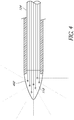
- FIGS 1A, 1B , and 2 illustrate a testing tool 100 in accordance with an embodiment of the present disclosure.
- the testing tool 100 contains a battery-powered light source (not shown) that emits light through the needle portion 116 of the testing tool 100.
- the light source may be configured to emit any type of light, including without limitation, one or more of visible light, non-visible light, ultraviolet light, polarized light, infrared light, and fluorescent light.
- the light source is used to aid in obtaining visual indications detectable by a light detector, such as a camera.
- the resulting light detected by the light detector can be used to determine many critical parameters associated with the injection such as, for example, the location of the injection, the pressure exerted by the user, the angle of the injection, the depth of the injection, and the like. This information can be detected by a light detector, for example by a camera, and communicated to a processing system and/or a user interface device or a display device for testing evaluation, display, and/or certification purposes.
- the testing tool 100 includes a plunger 110, a barrel 112, a needle assembly 114, a needle, 116, and a needle tip 118.
- the testing tool 100 may be activated by pressing a switch (not shown) which activates a light source, such as a light-emitting diode (LED) or laser diode, to emit a source of light.
- a light source such as a light-emitting diode (LED) or laser diode
- the driving light (which may also be referred to herein as the "driving light”) then travels through an optical fiber 124 positioned within a central lumen 122 of the needle 116.
- the optical fiber 124 entrains the driving light from the light source and directs the driving light in the longitudinal axis of the needle 116.
- the driving light travels through the optical fiber 124 and is delivered as a focused driving light to a distal portion of the needle tip 118.
- a light-transmissible barrier 126 Between the optical fiber 124 and the needle tip 118 is a light-transmissible barrier 126 which forms a sealed transparent enclosure 120 at the needle tip118.
- the sealed transparent enclosure is filled and/or coated with a fluorescent material.
- the optic fiber 124 positioned in the needle's central lumen 122 delivers the driving light at a wavelength that stimulates a fluorescing process in the fluorescent material located in the sealed transparent enclosure 120.
- Fluorescence is a process by which a driving light having a first wavelength is absorbed by a fluorescent material, and in response to the absorption, the fluorescent material emits a second light (referred to herein as a "fluorescent light") at a second wavelength that is typically at a lower energy level than the first, absorbed light.
- the fluorescent light is then emitted from the needle tip 118, which is surrounded by the transparent enclosure 120 having a closed point at a distal end of the needle tip 118.
- the transparent enclosure 120 is a glass structure.
- the transparent enclosure 120, including the light-transmissible barrier 126 may be made of many materials capable of containing the fluorescent material and permitting the fluorescent light to radiate through it.
- a property of fluorescent light is that it radiates substantially uniformly in all directions (also referred to herein as "omnidirectional") and is therefore detectable over a much broader angular range than that of the driving light emitted by means of an optical fiber 124 alone.
- the fluorescent light emitted by the fluorescent material can be detected by sensors 140 lateral to the testing tool's 100 (syringe's) axis.
- Figure 3 is a sectional schematic view, cut along line 2-2, of an embodiment of needle tip 118 of Figure 1B in which the needle tip is made of solid fluorescing material.
- the optical fiber 124 abuts to the needle tip 118 made of the solid fluorescent material.
- the solid tip may be made of ruby, treated glass, or other fluorescing materials.
- the needle tip 118 absorbs the high-energy driving light from the optical fiber 124 and emits a lower-energy fluorescent light that radiates substantially uniformly from the needle tip 118.
- this embodiment is simple to manufacture because it has fewer components than the embodiments described above with respect to Figure 2 .
- the transparent enclosure 120 can be challenging and/or costly to manufacture, fill with fluorescent material, seal, and test as compared to the solid-tip embodiment.
- the solid needle tip 118 embodiment disclosed in Figure 3 also provides an improved durability, as the solid fluorescent material may be more robust than a hollow transparent enclosure 120.
- the solid needle tip 118 may resist damage from both normal use and accidental impact.
- the solid-tip embodiment also provides improved needle tip 118 sharpness.
- the solid-tip fluorescent material may be precision ground to a point, while a hollow tip transparent enclosure 120 has comparatively thin walls and may frequently break when ground to a sharp point. Additionally, the solid-tip embodiment eliminates the risk of leaks of fluorescing liquid or gaseous materials that may be contained in the embodiments using a transparent enclosure 120.
- the fluorescent material used in the present embodiments may be liquid, solid, gaseous, or a combination such materials.
- fluorescent materials that may be used in the disclosed embodiments include ruby, ninhydrin, and fluorescein.
- ruby ninhydrin
- fluorescein fluorescein
- a skilled artisan will appreciate that there are numerous fluorescent materials that may be used to implement the disclosed embodiments.
- a database of fluorescent dyes along with their properties and applications can be accessed at http://www.fluorophores.tuqraz.at/.
- the improved detection range resulting from use of fluorescent light emitting from the needle tip 118 can support use of this technology in living tissue.
- the frequency of light from the fluorescing material can be tuned so as to pass through living tissue and allow detection from sensors that are positioned outside of the body. This can provide a source of information that can be used to perform improved needle placement during actual injection procedures as well as simulated procedures during training sessions.
- Figure 4 is a schematic sectional view of an embodiment of a needle tip118 that diffuses light emitted from the testing tool 100.
- Light diffusion is a process by which photons travel though a material without being absorbed; instead, the photons undergo a series of repeated scattering events which change the direction of the photons' paths. Thus, light-diffusing materials cause the light to radiate in a more omnidirectional manner.
- the optical fiber 124 is positioned within the central lumen 122 of the needle 116. The optical fiber 124 entrains the driving light from the light source and directs the driving light in the longitudinal axis of the needle 116.
- the light travels through the optical fiber 124 and is delivered as a focused driving light to a distal portion of the needle tip 118.
- the optical fiber 124 is configured to abut the distal end of the needle tip 118.
- the distal end of the needle tip 118 may be constructed of a light-diffusing material.
- One such light-diffusing material is glass having a diffusing agent 402 added.
- the diffusing agent 402 may be particles of white titanium dioxide, reflective metal powder, or other such agents.
- the needle tip 118 may be coated with a light-diffusing material. Provision of light-diffusing material at the needle tip 118 enables the conversion of the narrow and intense straight driving light path exiting the optical fiber 124 to one that is substantially omnidirectional, at reduced intensity. The result is that the needle tip 118 is observable at high angles off of the needle axis.
- the needle tip 118 includes both fluorescent material and light-diffusing material.
- the transparent enclosure 120 may be filled with a fluorescent material and have a light-diffusing coating on an interior surface, an exterior surface, or both an interior and exterior surface of the transparent enclosure 120.
- the transparent enclosure 120 may be made of glass having a light-diffusing agent added to the glass.
- the optical fiber 124 extends beyond the distal end of the needle to form the needle tip 118, having a point.
- the needle tip 118 formed by the optical fiber 124 may have a light-diffusing coating, or it may contain a light-diffusing material. In other embodiments, the needle tip 118 formed by the optical fiber 124 may be coated with a fluorescent material.
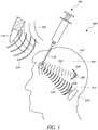
- Figure 5 is a sectional view of a surface fluorescing tip with an external source for driving light.
- Figure 5 illustrates an injection training system 500 according to an embodiment of the present disclosure.
- the system 500 includes an injection apparatus 502 having a clear interior space 504 and configured to receive a simulated injection by a testing tool 100.
- the injection apparatus 502 is a synthetic anatomical structure that can be used for any type of injection training involved with administering diagnostic and therapeutic chemical substances.
- injection training can be provided for epidural techniques and for intra-cardiac injections.
- the injection apparatus 502 can anatomically model the face, neck, and head of a human.
- the injection apparatus 502 can model other injection sites including the chest, arms, mouth, back, buttocks, etc.
- the injection apparatus 502 may also represent any body part of a human or animal, including internal organs.
- the injection apparatus 502 may include a simulated skull and layers of muscle and skin.
- the injection apparatus 502 can be positioned on a base to facilitate use on flat surfaces, such as a table or desk.
- a light source 506 Positioned within the interior 504 of the injection apparatus 502 is a light source 506 having one or more light reflectors 508. As illustrated in Figure 5 , the light source 506 is positioned within the interior 504 of the injection apparatus 502 so as to emit a driving light 520 generally in a direction of the simulated injection. Accordingly, the light source 506 and reflectors 508 are positioned toward a back portion of the head of the injection apparatus 502 and configured to emit the driving light 520 toward a face portion of the injection apparatus 502 where a simulated injection is performed.
- a light detector 510 is also positioned within the interior 504 of the injection apparatus 502.
- the light detector 510 is positioned toward the back portion of the head of the injection apparatus 502 near the light source 506 and configured to detect fluorescent light 530 emitted from the tip 118 of testing tool 100 used to perform the simulated injection.
- the light detector 510 includes a filter 512 configured to block one or more wavelengths of light from being detected by the light detector 510.
- the filter 512 may be configured to block the driving light 520 emitted from the light source 506 so as to ensure that the light detector only detects the fluorescent light 530 emitted from the needle tip 118.
- the needle tip 118 of the testing tool 100 includes fluorescent material.
- the light source 506 emits a driving light 520 that is delivered by, for example, a high-energy light emitter.
- the light source 506 emits ultraviolet light 520 as the driving light.
- the fluorescent needle tip 118 which has penetrated into the interior 504 of the injection apparatus 502, absorbs the emitted driving ultraviolet light 520, and in response to the absorption, emits fluorescent light 530 having a wavelength in the visible spectrum.
- the filter 512 can block the driving light 520 and pass only the fluorescent light 530 radiated by the fluorescent needle tip 118.
- This embodiment provides several benefits including eliminating the optical fiber 124 light path in the testing tool 100, offloading the power required for driving a light source 506 from the testing tool 100, extending battery life of the testing tool 100, and reducing the complexity of the testing tool 100.
- An injection training system has been disclosed in detail in connection with various embodiments.
- injection includes it usual and customary meaning of an injection, but is also to be interpreted broad enough to encompass, for example, the insertion of a catheter device or the use of simple needles, such as would be used in an acupuncture therapy.
- the techniques involved, particularly a camera embedded in a model of a living subject and a tool with a light emitter can be applied to any therapeutic procedure.
- the tool can be a catheter and the procedure can be a minimally invasive procedure requiring the catheter to be located in a particular location.
- acts, events, or functions of any of the methods described herein can be performed in a different sequence, can be added, merged, or left out altogether (for example, not all described acts or events are necessary for the practice of the method).
- acts or events can be performed concurrently, for example, through multi-threaded processing, interrupt processing, or multiple processors or processor cores, rather than sequentially.
Claims (14)
- Outil de test (100) comprenant :une aiguille (116) ayant une lumière centrale (122), une extrémité distale, une extrémité proximale, et une pointe (118) à l'extrémité distale de l'aiguille (116) ;un fût (112) coopérant avec l'extrémité proximale de l'aiguille (116) ;une source de lumière, positionnée dans le fût (112), la source de lumière étant configurée pour émettre de la lumière ; etune fibre optique (124) située à l'intérieur de la lumière centrale (122) de l'aiguille (116), la fibre optique (124) étant configurée pour recevoir la lumière émise à partir de la source de lumière et pour transmettre la lumière émise à travers l'aiguille (116) à partir de l'extrémité proximale vers l'extrémité distale de sorte que la lumière est émise vers la pointe (118) de l'aiguille (116),caractérisé en ce quela pointe d'aiguille (118) comprend un matériau fluorescent, etla pointe d'aiguille (118) est configurée pour émettre la lumière dans un motif substantiellement omnidirectionnel.
- Outil de test (100) selon la revendication 1, dans lequel la pointe d'aiguille (118) est configurée pour émettre de la lumière dans un motif substantiellement uniforme.
- Outil de test (100) selon l'une quelconque des revendications précédentes, dans lequel la source de lumière émet une première lumière ayant une première longueur d'onde, et la pointe d'aiguille (118) émet une seconde lumière ayant une seconde longueur d'onde.
- Outil de test (100) selon la revendication 3, dans lequel la pointe d'aiguille (118) est configurée pour absorber la première lumière et, en réponse à l'absorption de la première lumière, pour émettre la seconde lumière.
- Outil de test (100) selon l'une quelconque des revendications précédentes, dans lequel la pointe d'aiguille (118) comprend un réceptacle (120) transparent rempli avec un matériau fluorescent.
- Outil de test (100) selon la revendication 5, dans lequel le réceptacle (120) transparent comprend une extrémité distale ayant une pointe.
- Outil de test (100) selon l'une quelconque des revendications précédentes, dans lequel la pointe d'aiguille (118) comprend du verre ayant un agent de diffusion de la lumière (402) mélangé au verre.
- Outil de test (100) selon la revendication 7, dans lequel l'agent de diffusion de la lumière (402) comprend des particules de dioxyde de titane blanc ou une poudre métallique réfléchissante.
- Outil de test (100) selon l'une quelconque des revendications précédentes, dans lequel le matériau fluorescent comprend au moins un matériau liquide, un matériau solide, ou un matériau gazeux.
- Outil de test (100) selon la revendication 10, dans lequel le matériau fluorescent comprend le matériau solide, le matériau solide comprenant une pointe.
- Outil de test (100) selon l'une quelconque des revendications précédentes, dans lequel la pointe d'aiguille (118) comprend un matériau de diffusion de la lumière.
- Outil de test (100) selon la revendication 11, dans lequel la pointe d'aiguille (118) est revêtue avec le matériau de diffusion de la lumière.
- Outil de test (100) selon l'une quelconque des revendications précédentes, dans lequel la fibre optique (124) comprend une extrémité distale formant la pointe d'aiguille (118).
- Outil de test (100) selon l'une quelconque des revendications précédentes, dans lequel la pointe d'aiguille (118) est revêtue avec le matériau fluorescent.
Applications Claiming Priority (2)
| Application Number | Priority Date | Filing Date | Title |
|---|---|---|---|
| US201462085935P | 2014-12-01 | 2014-12-01 | |
| PCT/US2015/062798 WO2016089706A1 (fr) | 2014-12-01 | 2015-11-25 | Outil de formation à une injection émettant une lumière omnidirectionnelle |
Publications (2)
| Publication Number | Publication Date |
|---|---|
| EP3227880A1 EP3227880A1 (fr) | 2017-10-11 |
| EP3227880B1 true EP3227880B1 (fr) | 2018-09-26 |
Family
ID=55229788
Family Applications (1)
| Application Number | Title | Priority Date | Filing Date |
|---|---|---|---|
| EP15828554.4A Active EP3227880B1 (fr) | 2014-12-01 | 2015-11-25 | Outil de formation à une injection émettant une lumière omnidirectionnelle |
Country Status (6)
| Country | Link |
|---|---|
| US (1) | US10235904B2 (fr) |
| EP (1) | EP3227880B1 (fr) |
| KR (1) | KR20170102233A (fr) |
| CN (1) | CN107111963B (fr) |
| BR (1) | BR112017011443A2 (fr) |
| WO (1) | WO2016089706A1 (fr) |
Families Citing this family (15)
| Publication number | Priority date | Publication date | Assignee | Title |
|---|---|---|---|---|
| US9792836B2 (en) | 2012-10-30 | 2017-10-17 | Truinject Corp. | Injection training apparatus using 3D position sensor |
| WO2014070799A1 (fr) | 2012-10-30 | 2014-05-08 | Truinject Medical Corp. | Système d'entraînement à l'injection |
| WO2015109251A1 (fr) | 2014-01-17 | 2015-07-23 | Truinject Medical Corp. | Système de formation aux sites d'injection |
| US10290231B2 (en) | 2014-03-13 | 2019-05-14 | Truinject Corp. | Automated detection of performance characteristics in an injection training system |
| EP3227880B1 (fr) | 2014-12-01 | 2018-09-26 | Truinject Corp. | Outil de formation à une injection émettant une lumière omnidirectionnelle |
| WO2017070391A2 (fr) | 2015-10-20 | 2017-04-27 | Truinject Medical Corp. | Système d'injection |
| WO2017151441A2 (fr) | 2016-02-29 | 2017-09-08 | Truinject Medical Corp. | Dispositifs, procédés et systèmes de sécurité d'injection thérapeutique et cosmétique |
| WO2017151716A1 (fr) | 2016-03-02 | 2017-09-08 | Truinject Medical Corp. | Système de détermination de position tridimensionnelle d'un outil d'essai |
| US10849688B2 (en) | 2016-03-02 | 2020-12-01 | Truinject Corp. | Sensory enhanced environments for injection aid and social training |
| US10650703B2 (en) | 2017-01-10 | 2020-05-12 | Truinject Corp. | Suture technique training system |
| WO2018136901A1 (fr) | 2017-01-23 | 2018-07-26 | Truinject Corp. | Appareil de mesure de dose et de position de seringue |
| JP7165936B2 (ja) * | 2018-04-13 | 2022-11-07 | 国立研究開発法人理化学研究所 | トレーニング装置、画像処理方法、プログラム、および情報記録媒体 |
| US11373551B2 (en) | 2018-05-11 | 2022-06-28 | The Penn State Research Foundation | Low cost haptic force medical instrument insertion simulator |
| KR102083613B1 (ko) * | 2018-10-29 | 2020-03-02 | 상지대학교산학협력단 | 경혈 위치 교육의 성취도 평가를 위한 인체 모형 시스템 및 이를 이용한 침술 판단 방법 |
| CN113450637B (zh) * | 2021-07-12 | 2023-08-11 | 浙江欧健医用器材有限公司 | 护理教学用静脉输液器 |
Family Cites Families (254)
| Publication number | Priority date | Publication date | Assignee | Title |
|---|---|---|---|---|
| US3237340A (en) | 1963-10-30 | 1966-03-01 | Philip H Knott | Toy "blood sampling" syringe simulator |
| JPS5221420Y2 (fr) | 1973-12-26 | 1977-05-17 | ||
| US3941121A (en) | 1974-12-20 | 1976-03-02 | The University Of Cincinnati | Focusing fiber-optic needle endoscope |
| US4142517A (en) | 1976-07-23 | 1979-03-06 | Contreras Guerrero De Stavropo | Apparatus for extracting bone marrow specimens |
| US4356828A (en) | 1980-03-03 | 1982-11-02 | Khosrow Jamshidi | Bone marrow aspiration needle |
| US4311138A (en) * | 1980-03-10 | 1982-01-19 | Sugarman Edward D | Illuminated hypodermic needle |
| DE3160292D1 (en) | 1980-04-23 | 1983-07-07 | Contraves Ag | Canula with sensing means |
| US4515168A (en) | 1983-07-22 | 1985-05-07 | Chester Martin H | Clamp-on nerve stimulator and locator |
| US4566438A (en) | 1984-10-05 | 1986-01-28 | Liese Grover J | Fiber-optic stylet for needle tip localization |
| US4815313A (en) | 1987-11-16 | 1989-03-28 | Abbott Laboratories | Syringe pressure calibration reference |
| US4880971A (en) | 1988-02-17 | 1989-11-14 | Danisch Lee A | Fiber optic liquid level sensor |
| US4836632A (en) | 1988-05-16 | 1989-06-06 | National Magnetic Sensors Inc. | Fiber optic liquid level sensor |
| US5197476A (en) | 1989-03-16 | 1993-03-30 | Christopher Nowacki | Locating target in human body |
| US5295483A (en) | 1990-05-11 | 1994-03-22 | Christopher Nowacki | Locating target in human body |
| US5198877A (en) | 1990-10-15 | 1993-03-30 | Pixsys, Inc. | Method and apparatus for three-dimensional non-contact shape sensing |
| US6564087B1 (en) | 1991-04-29 | 2003-05-13 | Massachusetts Institute Of Technology | Fiber optic needle probes for optical coherence tomography imaging |
| US5249581A (en) | 1991-07-15 | 1993-10-05 | Horbal Mark T | Precision bone alignment |
| CA2073162C (fr) | 1991-07-31 | 1999-06-29 | Lee A. Danisch | Capteur de position et de deformation a fibre optique |
| US5241184A (en) | 1991-09-26 | 1993-08-31 | Electric Power Research Institute | Apparatus and method for quantizing remaining lifetime of transmission cable insulation |
| US5584701A (en) | 1992-05-13 | 1996-12-17 | University Of Florida Research Foundation, Incorporated | Self regulating lung for simulated medical procedures |
| US5391081A (en) | 1992-05-13 | 1995-02-21 | University Of Florida Research Foundation, Incorporated | Method and apparatus for simulating neuromuscular stimulation during medical surgery |
| AU6666894A (en) | 1993-04-22 | 1994-11-08 | Pixsys, Inc. | System for locating relative positions of objects |
| CN2175451Y (zh) * | 1993-09-06 | 1994-08-24 | 锦州医学院 | 声光仿头模型教具 |
| US5518407A (en) | 1993-11-02 | 1996-05-21 | Greenfield; Cathy L. | Anatomically correct artificial organ replicas for use as teaching aids |
| GB9407936D0 (en) | 1994-04-21 | 1994-06-15 | Univ Bristol | Training device |
| US5899692A (en) | 1995-05-10 | 1999-05-04 | Davis; Warren | Illuminated syringe tip and handpiece assembly |
| GB2309644B (en) | 1995-05-22 | 2000-05-31 | Wolfgang Wagner | A method and device for diagnosis and injection |
| US5651783A (en) | 1995-12-20 | 1997-07-29 | Reynard; Michael | Fiber optic sleeve for surgical instruments |
| IL116685A (en) | 1996-01-05 | 2000-07-16 | Vascular Technologies Ltd | Blood vessel entry indicator |
| US5828770A (en) | 1996-02-20 | 1998-10-27 | Northern Digital Inc. | System for determining the spatial position and angular orientation of an object |
| WO1997036192A1 (fr) | 1996-03-27 | 1997-10-02 | Paul Scherrer Institut | Dispositif et procede de determinaton de position |
| EP0836438B1 (fr) | 1996-04-29 | 2004-09-22 | Northern Digital Inc. | Systeme pour chirurgie guidee par image |
| WO1997045064A1 (fr) | 1996-05-29 | 1997-12-04 | Philips Electronics N.V. | Systeme de chirurgie guidee par l'image |
| US6064749A (en) | 1996-08-02 | 2000-05-16 | Hirota; Gentaro | Hybrid tracking for augmented reality using both camera motion detection and landmark tracking |
| US5727948A (en) | 1996-09-05 | 1998-03-17 | Jordan; Lynette S. | Syringe injection practice device |
| US6024576A (en) | 1996-09-06 | 2000-02-15 | Immersion Corporation | Hemispherical, high bandwidth mechanical interface for computer systems |
| US6127672A (en) | 1997-05-23 | 2000-10-03 | Canadian Space Agency | Topological and motion measuring tool |
| US5923417A (en) | 1997-09-26 | 1999-07-13 | Northern Digital Incorporated | System for determining the spatial position of a target |
| US6061644A (en) | 1997-12-05 | 2000-05-09 | Northern Digital Incorporated | System for determining the spatial position and orientation of a body |
| US6353226B1 (en) | 1998-11-23 | 2002-03-05 | Abbott Laboratories | Non-invasive sensor capable of determining optical parameters in a sample having multiple layers |
| US6217558B1 (en) | 1998-12-17 | 2001-04-17 | Filiberto P. Zadini | Apparatus for blood vessel type differentiation for syringes and guidewires placement devices |
| DE29904018U1 (de) | 1999-03-05 | 1999-06-02 | Bodenseewerk Geraetetech | Aktives Instrument zur Positionsbestimmung bei Navigationssystemen zur Unterstützung chirurgischer Eingriffe |
| US20030031993A1 (en) | 1999-08-30 | 2003-02-13 | Carla Pugh | Medical examination teaching and measurement system |
| US6288785B1 (en) | 1999-10-28 | 2001-09-11 | Northern Digital, Inc. | System for determining spatial position and/or orientation of one or more objects |
| DE10029529A1 (de) | 1999-12-23 | 2001-06-28 | Rohwedder Visotech Gmbh | Reflektorsystem zur Positionsbestimmung |
| WO2000022904A2 (fr) | 2000-02-02 | 2000-04-27 | Northern Digital Inc. | Dispositif pour determiner la position de parties du corps, et utilisation de ce dispositif |
| US6553326B1 (en) | 2000-04-07 | 2003-04-22 | Northern Digital Inc. | Errors in systems using magnetic fields to locate objects |
| AU2001260559A1 (en) | 2000-05-19 | 2001-11-26 | Simbionics Ltd. | Endoscopic tutorial system for the pancreatic system |
| ATE312364T1 (de) | 2000-07-26 | 2005-12-15 | Northern Digital Inc | Verfahren zur bestimmung der position eines sensorelementes |
| WO2002013164A1 (fr) | 2000-08-04 | 2002-02-14 | West Virginia University | Instruments et detection informatises destines a l'apprentissage de l'examen physique |
| US7665995B2 (en) | 2000-10-23 | 2010-02-23 | Toly Christopher C | Medical training simulator including contact-less sensors |
| US8556635B2 (en) | 2000-10-23 | 2013-10-15 | Christopher C. Toly | Physiological simulator for use as a brachial plexus nerve block trainer |
| US7857626B2 (en) | 2000-10-23 | 2010-12-28 | Toly Christopher C | Medical physiological simulator including a conductive elastomer layer |
| US7194296B2 (en) | 2000-10-31 | 2007-03-20 | Northern Digital Inc. | Flexible instrument with optical sensors |
| WO2002070980A1 (fr) | 2001-03-06 | 2002-09-12 | The Johns Hopkins University School Of Medicine | Système de simulation pour procédures médicales sous imagerie |
| WO2002083003A1 (fr) | 2001-04-11 | 2002-10-24 | Clarke Dana S | Identification de structures tissulaires lors de la progression d'un instrument |
| US6625563B2 (en) | 2001-06-26 | 2003-09-23 | Northern Digital Inc. | Gain factor and position determination system |
| US6485308B1 (en) | 2001-07-09 | 2002-11-26 | Mark K. Goldstein | Training aid for needle biopsy |
| NO20013450L (no) | 2001-07-11 | 2003-01-13 | Simsurgery As | Systemer og fremgangsmåter for interaktiv trening av prosedyrer |
| US6908460B2 (en) | 2001-08-28 | 2005-06-21 | Joseph Distefano | Apparatus for conveying a light source to an intravenous needle to kill blood pathogens |
| US20030055380A1 (en) | 2001-09-19 | 2003-03-20 | Flaherty J. Christopher | Plunger for patient infusion device |
| US6769286B2 (en) | 2001-09-27 | 2004-08-03 | The Johns Hopkins University | Instrumented torso model |
| US7247149B2 (en) | 2001-12-20 | 2007-07-24 | Advanced Cardiovascular Systems, Inc. | Contact and penetration depth sensor for a needle assembly |
| US8277411B2 (en) | 2002-01-31 | 2012-10-02 | Boston Scientific Scimed, Inc. | Needle device |
| US6774624B2 (en) | 2002-03-27 | 2004-08-10 | Ge Medical Systems Global Technology Company, Llc | Magnetic tracking system |
| US20040009459A1 (en) | 2002-05-06 | 2004-01-15 | Anderson James H. | Simulation system for medical procedures |
| IES20030352A2 (en) | 2002-05-10 | 2003-10-15 | Haptica Ltd | A surgical training simulator |
| NZ555692A (en) * | 2002-07-19 | 2009-02-28 | Abbott Biotech Ltd | Treatment of TNF alpha related disorders |
| US6702790B1 (en) | 2002-10-31 | 2004-03-09 | Chauncey F. Ross | Hypodermic needle |
| US7697972B2 (en) | 2002-11-19 | 2010-04-13 | Medtronic Navigation, Inc. | Navigation system for cardiac therapies |
| US6931951B2 (en) | 2002-12-20 | 2005-08-23 | Kimberly-Clark Worldwide, Inc. | Mechanical device with simulated skin substrate |
| EP2319404B1 (fr) | 2003-01-24 | 2015-03-11 | The General Hospital Corporation | Système et procédé pour identifier des tissus à l'aide d'interférométrie à faible cohérence |
| US20060264745A1 (en) | 2003-03-17 | 2006-11-23 | Da Silva Luiz B | Optical biopsy system with single use needle probe |
| CA2433205A1 (fr) | 2003-03-18 | 2004-09-18 | James Alexander Keenan | Dispositif d'administration de medicaments, de drainage de fluides corporels et de biopsie a visibilite ultrasonore amelioree |
| US7783441B2 (en) | 2003-04-17 | 2010-08-24 | Northern Digital Inc. | Eddy current detection and compensation |
| GB0308938D0 (en) | 2003-04-17 | 2003-05-28 | Limbs And Things Ltd | Medical training system |
| US7158754B2 (en) | 2003-07-01 | 2007-01-02 | Ge Medical Systems Global Technology Company, Llc | Electromagnetic tracking system and method using a single-coil transmitter |
| US6888341B2 (en) | 2003-09-16 | 2005-05-03 | Snap-On Incorporated | Dual voltage circuit tester |
| US8007281B2 (en) | 2003-09-24 | 2011-08-30 | Toly Christopher C | Laparoscopic and endoscopic trainer including a digital camera with multiple camera angles |
| US7594815B2 (en) | 2003-09-24 | 2009-09-29 | Toly Christopher C | Laparoscopic and endoscopic trainer including a digital camera |
| US7015859B2 (en) | 2003-11-14 | 2006-03-21 | General Electric Company | Electromagnetic tracking system and method using a three-coil wireless transmitter |
| US20060084050A1 (en) | 2004-01-12 | 2006-04-20 | Haluck Randy S | Portable virtual reality medical demonstration and training apparatus |
| WO2005083653A1 (fr) | 2004-02-24 | 2005-09-09 | Cedars-Sinai Medical Center | Dispositif d'entrainement a la chirurgie laparoscopique a placement d'instruments reglable |
| CN103143079B (zh) | 2004-03-03 | 2016-09-28 | 株式会社根本杏林堂 | 药液注入系统 |
| US8131342B2 (en) | 2004-08-24 | 2012-03-06 | General Electric Company | Method and system for field mapping using integral methodology |
| CN2751386Y (zh) | 2004-11-25 | 2006-01-11 | 刘霄飞 | 皮内注射训练模型 |
| US10026338B2 (en) | 2004-11-30 | 2018-07-17 | The Regents Of The University Of California | Embedded motion sensing technology for integration within commercial ultrasound probes |
| US7383728B2 (en) | 2005-07-13 | 2008-06-10 | Ultimate Balance, Inc. | Orientation and motion sensing in athletic training systems, physical rehabilitation and evaluation systems, and hand-held devices |
| WO2008018889A2 (fr) | 2005-09-29 | 2008-02-14 | The General Hospital Corporation | Procédés et appareil pour la simulation autonome d'un accident |
| NL1030440C2 (nl) | 2005-11-16 | 2007-05-21 | Univ Twente | Bewegingsvolgsysteem. |
| US20090046140A1 (en) | 2005-12-06 | 2009-02-19 | Microvision, Inc. | Mobile Virtual Reality Projector |
| US20090305213A1 (en) | 2005-12-23 | 2009-12-10 | Rainer Burgkart | Simulationsvorrichtung zum simulieren von eindringvorgängen |
| DE202005021286U1 (de) | 2005-12-23 | 2007-08-09 | Burgkart, Rainer, Dr. med. | Simulationsvorrichtung zum Simulieren von Eindringvorgängen |
| WO2007090288A1 (fr) | 2006-02-09 | 2007-08-16 | Northern Digital Inc. | Système de suivi de marqueurs rétroréfléchissants |
| US20070238981A1 (en) | 2006-03-13 | 2007-10-11 | Bracco Imaging Spa | Methods and apparatuses for recording and reviewing surgical navigation processes |
| IL177080A0 (en) | 2006-03-15 | 2007-08-19 | Israel Aerospace Ind Ltd | Combat training system and method |
| WO2007109540A2 (fr) | 2006-03-17 | 2007-09-27 | The General Hospital Corporation | Appareil, procédé et support accessible par ordinateur pour l'identification de caractéristiques d'au moins une partie d'un vaisseau sanguin compris à l'intérieur d'un tissu au moyen d'une interférométrie faible cohérence à domaine spectral |
| AU2011218649B8 (en) | 2006-03-29 | 2015-11-19 | Kaleo, Inc. | Devices, systems and methods for medicament delivery |
| US7553159B1 (en) | 2006-05-12 | 2009-06-30 | Ams Research Corporation | Abdominopelvic region surgical training model |
| TWI527603B (zh) | 2006-06-30 | 2016-04-01 | 艾伯維生物技術有限責任公司 | 自動注射裝置 |
| US20080097378A1 (en) | 2006-08-02 | 2008-04-24 | Zuckerman Stephen D | Optical device for needle placement into a joint |
| US8376754B2 (en) | 2006-08-14 | 2013-02-19 | Brigitte Segal | Training aid for a dental injection |
| US8040127B2 (en) | 2006-08-15 | 2011-10-18 | General Electric Company | Multi-sensor distortion mapping method and system |
| US8442619B2 (en) | 2006-08-30 | 2013-05-14 | General Electric Company | System and method for detecting errors in position tracking systems used for medical applications |
| CA2663077A1 (fr) | 2006-09-15 | 2008-03-20 | Tufts University | Environnements dynamiques de formation et de test mini-invasifs |
| WO2008052348A1 (fr) | 2006-11-02 | 2008-05-08 | Northern Digital Inc. | Système d'affectation intégré |
| FR2909001B1 (fr) | 2006-11-24 | 2009-12-18 | Bernard Perriere | Dispositif d'injection et de prelevement miniaturise et automatique a usage medical. |
| US20080138781A1 (en) | 2006-12-08 | 2008-06-12 | Warsaw Orthopedic, Inc. | Surgical training model and method for use in facilitating training of a surgical procedure |
| US20100071467A1 (en) | 2008-09-24 | 2010-03-25 | Invensense | Integrated multiaxis motion sensor |
| US8462109B2 (en) | 2007-01-05 | 2013-06-11 | Invensense, Inc. | Controlling and accessing content using motion processing on mobile devices |
| US20090265671A1 (en) | 2008-04-21 | 2009-10-22 | Invensense | Mobile devices with motion gesture recognition |
| US8250921B2 (en) | 2007-07-06 | 2012-08-28 | Invensense, Inc. | Integrated motion processing unit (MPU) with MEMS inertial sensing and embedded digital electronics |
| US20080176198A1 (en) | 2007-01-19 | 2008-07-24 | Murtuza Ansari | System and method for dental education simulation |
| WO2008091838A2 (fr) | 2007-01-22 | 2008-07-31 | Intelliject, Inc. | Injecteur médical équipé d'un système de détection et de surveillance de l'observance |
| EP1970005B1 (fr) | 2007-03-15 | 2012-10-03 | Xsens Holding B.V. | Système et procédé du suivi du mouvement en utilisant une unité d'étalonnage |
| WO2008122006A1 (fr) | 2007-04-02 | 2008-10-09 | Mountaintop Technologies, Inc. | Procédé et appareil d'entraînement médical virtuel par ordinateur |
| US8203487B2 (en) | 2009-08-03 | 2012-06-19 | Xsens Holding, B.V. | Tightly coupled UWB/IMU pose estimation system and method |
| US20110046915A1 (en) | 2007-05-15 | 2011-02-24 | Xsens Holding B.V. | Use of positioning aiding system for inertial motion capture |
| US8408918B2 (en) | 2007-06-27 | 2013-04-02 | Energid Technologies Corporation | Method and apparatus for haptic simulation |
| US20110202012A1 (en) | 2007-08-16 | 2011-08-18 | Bartlett Edwin C | Smart Injection Syring Systems Providing Real-Time User Feedback of Correct Needle Position |
| US8409140B2 (en) | 2007-08-17 | 2013-04-02 | Medtronic Minimed, Inc. | Injection apparatus |
| KR100918480B1 (ko) | 2007-09-03 | 2009-09-28 | 한국전자통신연구원 | 스테레오 비전 시스템 및 그 처리 방법 |
| US7912662B2 (en) | 2007-09-24 | 2011-03-22 | General Electric Company | System and method for improving the distortion tolerance of an electromagnetic tracking system |
| US8469715B2 (en) | 2007-09-26 | 2013-06-25 | Rose Marie Ambrozio | Dynamic human model |
| US9456766B2 (en) | 2007-11-26 | 2016-10-04 | C. R. Bard, Inc. | Apparatus for use with needle insertion guidance system |
| US8454368B2 (en) | 2007-11-29 | 2013-06-04 | Cedars-Sinai Medical Center | Medical training methods and devices |
| WO2009094646A2 (fr) | 2008-01-24 | 2009-07-30 | The University Of North Carolina At Chapel Hill | Procédés, systèmes et supports lisibles par ordinateur pour ablation guidée par imagerie |
| US8764450B2 (en) | 2008-02-15 | 2014-07-01 | Carla M. Pugh | Clinical assessment and training system |
| WO2009117419A2 (fr) | 2008-03-17 | 2009-09-24 | Worcester Polytechnic Institute | Système virtuel interactif pour la formation en ultrasons |
| CN201213049Y (zh) | 2008-03-19 | 2009-03-25 | 天津市天堰医教科技开发有限公司 | 皮内注射练习模型 |
| US20090263775A1 (en) | 2008-04-22 | 2009-10-22 | Immersion Medical | Systems and Methods for Surgical Simulation and Training |
| WO2009141769A1 (fr) | 2008-05-19 | 2009-11-26 | Koninklijke Philips Electronics N.V. | Positionnement reproductible de dispositifs de détection et/ou de traitement |
| WO2009144622A1 (fr) | 2008-05-26 | 2009-12-03 | Koninklijke Philips Electronics N.V. | Dispositif indicateur d'emplacement |
| JP4517004B2 (ja) | 2008-06-16 | 2010-08-04 | ノリー株式会社 | 注射針誘導装置 |
| US8257250B2 (en) | 2008-06-23 | 2012-09-04 | Intubrite, Llc | Laryngoscope and method of use |
| US8864652B2 (en) | 2008-06-27 | 2014-10-21 | Intuitive Surgical Operations, Inc. | Medical robotic system providing computer generated auxiliary views of a camera instrument for controlling the positioning and orienting of its tip |
| US8655622B2 (en) | 2008-07-05 | 2014-02-18 | Ailive, Inc. | Method and apparatus for interpreting orientation invariant motion |
| US9280913B2 (en) | 2009-07-10 | 2016-03-08 | Lincoln Global, Inc. | Systems and methods providing enhanced education and training in a virtual reality environment |
| US9017080B1 (en) | 2008-08-29 | 2015-04-28 | Otto J. Placik | System and method for teaching injection techniques of the human head and face |
| US8437833B2 (en) | 2008-10-07 | 2013-05-07 | Bard Access Systems, Inc. | Percutaneous magnetic gastrostomy |
| US20100099066A1 (en) | 2008-10-21 | 2010-04-22 | Warsaw Orthopedics, Inc. | Surgical Training System and Model With Simulated Neural Responses and Elements |
| US20110301500A1 (en) | 2008-10-29 | 2011-12-08 | Tim Maguire | Automated vessel puncture device using three-dimensional(3d) near infrared (nir) imaging and a robotically driven needle |
| US8535062B2 (en) | 2008-12-23 | 2013-09-17 | Simskin, Llc | Cutaneous surgical training model of the head, neck and shoulders |
| US20100167249A1 (en) | 2008-12-31 | 2010-07-01 | Haptica Ltd. | Surgical training simulator having augmented reality |
| TWI399532B (zh) | 2009-01-20 | 2013-06-21 | Nat Chung Cheng University Inv | Optical fiber type localized plasma resonance sensing device and its system |
| WO2010084440A1 (fr) | 2009-01-22 | 2010-07-29 | Koninklijke Philips Electronics N.V. | Interprétation de données d'orientation angulaire |
| US8218142B2 (en) | 2009-02-17 | 2012-07-10 | The Boeing Company | Fiber optic probe scatterometer for spectroscopy measurements |
| JP5221420B2 (ja) | 2009-03-06 | 2013-06-26 | テルモ株式会社 | 注射器、注射実技用模擬腕および注射実技記録再生装置 |
| BRPI1014540A2 (pt) | 2009-04-09 | 2016-04-05 | Dalhouse University | método e sistema para a medição de energia de cura entregue durante restaurações dentárias simuladas. |
| US8945147B2 (en) | 2009-04-27 | 2015-02-03 | Smith & Nephew, Inc. | System and method for identifying a landmark |
| US8450997B2 (en) | 2009-04-28 | 2013-05-28 | Brown University | Electromagnetic position and orientation sensing system |
| US8342853B2 (en) | 2009-04-28 | 2013-01-01 | Immersion Corporation | System for displaying and interacting with palpatable feature |
| US20110027767A1 (en) | 2009-07-29 | 2011-02-03 | Divinagracia Glenn J | Anthropomorphic mannequin |
| CA2777092C (fr) | 2009-10-06 | 2019-12-03 | Smith & Nephew, Inc. | Ciblage de points de repere de dispositifs orthopediques |
| WO2011043645A1 (fr) | 2009-10-08 | 2011-04-14 | Personal Space Technologies | Système d'affichage et procédé d'affichage d'un modèle tridimensionnel d'un objet |
| US9373270B2 (en) | 2009-10-15 | 2016-06-21 | Douglas Wayne Miyazaki | Pelvic surgery training model |
| WO2011051458A1 (fr) | 2009-11-02 | 2011-05-05 | Bangor University | Aiguille haptique en tant que partie d'un simulateur médical d'entraînement |
| US9486162B2 (en) | 2010-01-08 | 2016-11-08 | Ultrasonix Medical Corporation | Spatial needle guidance system and associated methods |
| KR101250796B1 (ko) | 2010-02-02 | 2013-04-04 | 한국과학기술연구원 | 주사 시뮬레이션 시스템 및 방법 |
| US8500452B2 (en) | 2010-02-19 | 2013-08-06 | Gaumard Scientific Company, Inc. | Interactive education system for teaching patient care |
| DE102011013398A1 (de) | 2010-03-10 | 2011-09-15 | Northern Digital Inc. | Magnetisches Ortungssystem |
| US20110236866A1 (en) | 2010-03-25 | 2011-09-29 | Psaltis Gregory L | Anesthetic Injection Training and Testing System |
| WO2011127379A2 (fr) | 2010-04-09 | 2011-10-13 | University Of Florida Research Foundation Inc. | Système interactif de réalité mélangée et ses utilisations |
| CA2736841C (fr) | 2010-04-15 | 2014-02-18 | Teneo Innovations Inc. | Dispositif et dispositif de commande electronique pour la commande d'un piston de seringue |
| WO2011136778A1 (fr) | 2010-04-29 | 2011-11-03 | Dermsurg Scientific, Llc | Modèle de formation à la chirurgie cutanée pour la tête, le cou et les épaules |
| CA2739030C (fr) | 2010-05-03 | 2017-11-21 | Northern Digital Inc. | Etablir des systemes de coordonnees pour realiser des mesures |
| EP2756857B1 (fr) | 2010-05-19 | 2016-05-18 | Allergan, Inc. | Dispositif d'injection modulaire |
| US8714984B2 (en) | 2010-07-16 | 2014-05-06 | One World Design and Manufacturing Group, LTD | Injection simulator |
| KR101202848B1 (ko) | 2010-07-21 | 2012-11-20 | 주식회사 비티 | 가상현실과 햅틱기술이 적용된 주사 훈련용 시뮬레이터 |
| US8319182B1 (en) | 2010-07-27 | 2012-11-27 | The Boeing Company | Methods and systems for using IR spectroscopy to quantify degradation of wiring insulation |
| TW201207785A (en) | 2010-08-13 | 2012-02-16 | Eped Inc | Dental anesthesia injection training simulation system and evaluation method thereof |
| WO2012055071A1 (fr) | 2010-10-28 | 2012-05-03 | 医百科技股份有限公司 | Système et procédé de simulation d'injection dentaire |
| US20120130269A1 (en) | 2010-11-19 | 2012-05-24 | Neural Pathways, Llc | Integrated nerve stimulation and skin marking device and methods of using same |
| WO2012075166A1 (fr) | 2010-11-30 | 2012-06-07 | Cae Healthcare Inc. | Module d'œil pour mannequin de simulation de patient |
| JP5550050B2 (ja) | 2010-12-14 | 2014-07-16 | 株式会社ティー・エム・シー | 人体の部分模型 |
| US20120171652A1 (en) | 2010-12-15 | 2012-07-05 | Sparks Jessica L | Pressure Ulcer Simulator and Related Methods |
| US9364171B2 (en) | 2010-12-22 | 2016-06-14 | Veebot Systems, Inc. | Systems and methods for autonomous intravenous needle insertion |
| AU2015255197B2 (en) | 2011-01-26 | 2019-03-28 | Kaleo, Inc. | Medicament delivery devices for administration of a medicament within a prefilled syringe |
| WO2012101286A1 (fr) | 2011-01-28 | 2012-08-02 | Virtual Proteins B.V. | Procédures d'insertion en réalité augmentée |
| WO2012106706A2 (fr) | 2011-02-04 | 2012-08-09 | University Of Pittsburgh - Of The Commonwealth System Of Higher Education | Simulation de réalité hybride physique-virtuelle pour apprentissage clinique pouvant fournir une rétroaction à un modèle anatomique physique |
| US8632498B2 (en) | 2011-02-11 | 2014-01-21 | TauTona Group Research and Development Company, L.L.C. | Tissue transfer systems |
| US8517740B2 (en) | 2011-02-18 | 2013-08-27 | Gaumard Scientific Company, Inc. | Lung compliance simulation system and associated methods |
| US10354555B2 (en) | 2011-05-02 | 2019-07-16 | Simbionix Ltd. | System and method for performing a hybrid simulation of a medical procedure |
| US20140081208A1 (en) | 2011-05-11 | 2014-03-20 | Isto Technologies, Inc. | Injection pressure monitoring device and system |
| EP2538398B1 (fr) | 2011-06-19 | 2015-08-26 | Centrum Transferu Technologii Medycznych Park Technologiczny Sp. z o.o. | Système et procédé pour simulations d'échocardiographie transoesophagienne |
| US8843345B2 (en) | 2011-06-20 | 2014-09-23 | Invensense, Inc. | Motion determination |
| US20130018494A1 (en) | 2011-07-14 | 2013-01-17 | Alexander Andre Amini | System and method for motion analysis and feedback with ongoing dynamic training orientation determination |
| JP5520263B2 (ja) | 2011-08-05 | 2014-06-11 | 株式会社坂本モデル | 血管注射シミュレータ |
| WO2013025639A1 (fr) | 2011-08-17 | 2013-02-21 | Invensense, Inc. | Polarisation de magnétomètre et détecteur d'anomalie |
| US8577640B2 (en) | 2011-08-17 | 2013-11-05 | Invensense, Inc. | Magnetometer bias and anomaly detector |
| JP2013088898A (ja) | 2011-10-14 | 2013-05-13 | Sony Corp | 3dデータ解析のための装置、方法及びプログラムと、微小粒子解析システム |
| US9098908B2 (en) | 2011-10-21 | 2015-08-04 | Microsoft Technology Licensing, Llc | Generating a depth map |
| GB201118773D0 (en) | 2011-10-31 | 2011-12-14 | Univ Bristol | Probe |
| CN104244816B (zh) | 2011-11-22 | 2018-08-31 | 阿森松技术公司 | 导丝跟踪 |
| US9439653B2 (en) | 2011-12-07 | 2016-09-13 | Traumatek Solutions B.V. | Devices and methods for endovascular access and therapy |
| US11026600B2 (en) | 2012-01-09 | 2021-06-08 | Invensense, Inc. | Activity classification in a multi-axis activity monitor device |
| US9683865B2 (en) | 2012-01-26 | 2017-06-20 | Invensense, Inc. | In-use automatic calibration methodology for sensors in mobile devices |
| US20130198625A1 (en) | 2012-01-26 | 2013-08-01 | Thomas G Anderson | System For Generating Haptic Feedback and Receiving User Inputs |
| MX347426B (es) | 2012-03-02 | 2017-04-26 | Abbvie Inc | Aparato de entrenamiento de inyeccion automatica. |
| US20130267838A1 (en) | 2012-04-09 | 2013-10-10 | Board Of Regents, The University Of Texas System | Augmented Reality System for Use in Medical Procedures |
| US20130296691A1 (en) | 2012-05-04 | 2013-11-07 | Ascension Technology Corporation | Magnetically tracked surgical needle assembly |
| CN102708745B (zh) | 2012-05-17 | 2015-09-16 | 徐州医学院 | 一种穿刺操作训练装置 |
| JP5380579B2 (ja) | 2012-05-31 | 2014-01-08 | 学校法人東日本学園・北海道医療大学 | 注射シミュレータ |
| EP2674184A1 (fr) | 2012-06-15 | 2013-12-18 | Ares Trading S.A. | Dispositif d'injection avec capteur d'aiguille |
| EP2698180A1 (fr) | 2012-08-15 | 2014-02-19 | Sanofi-Aventis Deutschland GmbH | Auto-injecteur |
| US20140102167A1 (en) | 2012-10-12 | 2014-04-17 | Northern Digital, Inc. | Force platform |
| KR101397522B1 (ko) | 2012-10-15 | 2014-05-27 | 건국대학교 산학협력단 | 증강 현실 기반의 정맥 주사 훈련 시뮬레이터 시스템 및 방법 |
| WO2014070799A1 (fr) | 2012-10-30 | 2014-05-08 | Truinject Medical Corp. | Système d'entraînement à l'injection |
| US9550029B2 (en) | 2012-10-30 | 2017-01-24 | Elwha Llc | Systems and methods for guiding injections |
| US9792836B2 (en) | 2012-10-30 | 2017-10-17 | Truinject Corp. | Injection training apparatus using 3D position sensor |
| US9384680B2 (en) | 2012-12-06 | 2016-07-05 | Bt Inc. | Intramuscular injection training model |
| US8994366B2 (en) | 2012-12-12 | 2015-03-31 | Ascension Technology Corporation | Magnetically tracked sensor |
| EP2931336B1 (fr) | 2012-12-13 | 2017-06-14 | Medicom Innovation Partner a/s | Dispositif de détection et dispositif d'injection le comprenant |
| CA2896068C (fr) | 2012-12-21 | 2022-07-05 | Deka Products Limited Partnership | Pompe de seringue, et procede et systeme associes |
| ES2668480T3 (es) | 2012-12-28 | 2018-05-18 | Gambro Lundia Ab | Aparato de detección de acoplamiento de bomba de jeringa y métodos |
| JP5649676B2 (ja) | 2013-02-06 | 2015-01-07 | 株式会社ケー・シー・シー・商会 | 注射練習具 |
| US20140244209A1 (en) | 2013-02-22 | 2014-08-28 | InvenSense, Incorporated | Systems and Methods for Activity Recognition Training |
| WO2014136016A1 (fr) | 2013-03-05 | 2014-09-12 | Koninklijke Philips N.V. | Acquisitions par ultrasons séquentielles cohérentes pour une surveillance intracrânienne |
| US20140278205A1 (en) | 2013-03-12 | 2014-09-18 | Invensense, Inc. | Embedded processor on an integrated mems sensor chip autonomously managing external sensor |
| US10132829B2 (en) | 2013-03-13 | 2018-11-20 | Invensense, Inc. | Heading confidence interval estimation |
| US10247748B2 (en) | 2013-03-15 | 2019-04-02 | Invensense, Inc. | Method to reduce data rates and power consumption using device based attitude generation |
| US20140260704A1 (en) | 2013-03-15 | 2014-09-18 | Invensense, Inc. | Device and system for integrated sensor system (iss) |
| EP2784766A1 (fr) | 2013-03-28 | 2014-10-01 | F. Hoffmann-La Roche AG | Dispositif d'entraînement pour dispositifs d'injection de médicament et dispositif de réinitialisation pour réinitialiser un tel appareil d'entraînement |
| JP6511442B2 (ja) | 2013-08-02 | 2019-05-15 | ユニオン・メディコ・エイピイエス | 注射デバイス |
| US20150079545A1 (en) | 2013-09-16 | 2015-03-19 | Thomas R. Kurtz | Systems and methods for automated flight instruction and certification |
| WO2015109251A1 (fr) | 2014-01-17 | 2015-07-23 | Truinject Medical Corp. | Système de formation aux sites d'injection |
| WO2015110327A1 (fr) | 2014-01-21 | 2015-07-30 | Carebay Europe Ltd | Dispositif de formation pour realiser une injection |
| WO2015136564A1 (fr) | 2014-03-10 | 2015-09-17 | Osvaldo Tufi | Module d'extension de surveillance et de contrôle d'observance d'une thérapie pour des médicaments injectables contenus dans des seringues préremplies |
| US10290231B2 (en) | 2014-03-13 | 2019-05-14 | Truinject Corp. | Automated detection of performance characteristics in an injection training system |
| EP3138091B1 (fr) | 2014-03-13 | 2020-06-10 | Truinject Corp. | Détection automatisée des caractéristiques de performance dans un système de formation à l'administration d'injections |
| US10083630B2 (en) | 2014-04-17 | 2018-09-25 | University of Pittsburgh—of the Commonwealth System of Higher Education | Modular, wireless, drug simulant injection sensor system and methods of employing |
| ES2935770T3 (es) | 2014-05-06 | 2023-03-09 | Univ North Carolina Chapel Hill | Dispositivos, sistemas y procedimientos para medir volumétricamente fluido en una jeringa |
| US9460638B2 (en) | 2014-06-30 | 2016-10-04 | Jeff Baker | Smart injection training device and system |
| EP3227880B1 (fr) | 2014-12-01 | 2018-09-26 | Truinject Corp. | Outil de formation à une injection émettant une lumière omnidirectionnelle |
| WO2016123144A2 (fr) | 2015-01-26 | 2016-08-04 | Jeff Baker | Dispositif de simulation d'injection et procédé |
| MX2017009652A (es) | 2015-01-26 | 2018-04-10 | Becton Dickinson Co | Dispositivo de captura de dosis para jeringas. |
| WO2016162298A1 (fr) | 2015-04-07 | 2016-10-13 | Albert Sinfreu Alay | Module portable de détection d'une perfusion du contenu d'une seringue |
| WO2016191127A1 (fr) | 2015-05-22 | 2016-12-01 | Afl Telecommunications Llc | Assemblages de fibres optiques et leurs procédés de formation |
| CN105118350B (zh) | 2015-07-31 | 2017-06-23 | 大连理工大学 | 一种新型可量化静脉注射及穿刺模拟训练装置 |
| WO2017048931A1 (fr) | 2015-09-15 | 2017-03-23 | University Of Florida Research Foundation, Incorporated | Simulateurs d'insertion d'outil médical guidée par ultrasons |
| WO2017048929A1 (fr) | 2015-09-15 | 2017-03-23 | University Of Florida Research Foundation, Incorporated | Simulateurs d'introduction d'outil médical guidée par ultrasons |
| JP6884152B2 (ja) | 2015-09-23 | 2021-06-09 | サノフィ−アベンティス・ドイチュラント・ゲゼルシャフト・ミット・ベシュレンクテル・ハフツング | 注射デバイスに取り付けるデバイス |
| US11087640B2 (en) | 2015-10-05 | 2021-08-10 | Shl Medical Ag | Medicament delivery training device |
| WO2017070391A2 (fr) | 2015-10-20 | 2017-04-27 | Truinject Medical Corp. | Système d'injection |
| US20170178540A1 (en) | 2015-12-22 | 2017-06-22 | Truinject Medical Corp. | Injection training with modeled behavior |
| CN205541594U (zh) | 2016-02-05 | 2016-08-31 | 上海市杨浦区市东医院 | 静脉注射练习模型 |
| WO2017151441A2 (fr) | 2016-02-29 | 2017-09-08 | Truinject Medical Corp. | Dispositifs, procédés et systèmes de sécurité d'injection thérapeutique et cosmétique |
| WO2017151716A1 (fr) | 2016-03-02 | 2017-09-08 | Truinject Medical Corp. | Système de détermination de position tridimensionnelle d'un outil d'essai |
| US10849688B2 (en) | 2016-03-02 | 2020-12-01 | Truinject Corp. | Sensory enhanced environments for injection aid and social training |
| EP3427244B1 (fr) | 2016-03-07 | 2020-09-09 | SHL Medical AG | Dispositif d'apprentissage d'injection automatique |
| CN107067856B (zh) | 2016-12-31 | 2020-03-27 | 歌尔科技有限公司 | 一种医学模拟训练系统和方法 |
| US10650703B2 (en) | 2017-01-10 | 2020-05-12 | Truinject Corp. | Suture technique training system |
| WO2018136901A1 (fr) | 2017-01-23 | 2018-07-26 | Truinject Corp. | Appareil de mesure de dose et de position de seringue |
| CN106710413A (zh) | 2017-02-21 | 2017-05-24 | 上海市同仁医院 | 一种医疗训练的面部注射仿真头像仪及其工作方法 |
-
2015
- 2015-11-25 EP EP15828554.4A patent/EP3227880B1/fr active Active
- 2015-11-25 WO PCT/US2015/062798 patent/WO2016089706A1/fr active Application Filing
- 2015-11-25 KR KR1020177016412A patent/KR20170102233A/ko unknown
- 2015-11-25 US US14/952,809 patent/US10235904B2/en active Active
- 2015-11-25 CN CN201580072045.2A patent/CN107111963B/zh active Active
- 2015-11-25 BR BR112017011443A patent/BR112017011443A2/pt not_active Application Discontinuation
Non-Patent Citations (1)
| Title |
|---|
| None * |
Also Published As
| Publication number | Publication date |
|---|---|
| KR20170102233A (ko) | 2017-09-08 |
| US10235904B2 (en) | 2019-03-19 |
| CN107111963B (zh) | 2020-11-17 |
| WO2016089706A1 (fr) | 2016-06-09 |
| BR112017011443A2 (pt) | 2018-02-27 |
| CN107111963A (zh) | 2017-08-29 |
| EP3227880A1 (fr) | 2017-10-11 |
| US20160155363A1 (en) | 2016-06-02 |
Similar Documents
| Publication | Publication Date | Title |
|---|---|---|
| EP3227880B1 (fr) | Outil de formation à une injection émettant une lumière omnidirectionnelle | |
| US11403964B2 (en) | System for cosmetic and therapeutic training | |
| US20220309954A1 (en) | Injection training apparatus using 3d position sensor | |
| US10743942B2 (en) | Cosmetic and therapeutic injection safety systems, methods, and devices | |
| US10648790B2 (en) | System for determining a three-dimensional position of a testing tool | |
| US9550029B2 (en) | Systems and methods for guiding injections | |
| US10046119B2 (en) | Systems and methods for generating an injection guide | |
| US20100121252A1 (en) | Non-invasive vascular treatment systems, devices, and methods of using the same | |
| JP2000316866A (ja) | 血管の視認方法及び血管の視認装置 | |
| GB2519637A (en) | System for injection training | |
| JP2004187936A (ja) | 生体組織探索装置 |
Legal Events
| Date | Code | Title | Description |
|---|---|---|---|
| STAA | Information on the status of an ep patent application or granted ep patent |
Free format text: STATUS: THE INTERNATIONAL PUBLICATION HAS BEEN MADE |
|
| PUAI | Public reference made under article 153(3) epc to a published international application that has entered the european phase |
Free format text: ORIGINAL CODE: 0009012 |
|
| STAA | Information on the status of an ep patent application or granted ep patent |
Free format text: STATUS: REQUEST FOR EXAMINATION WAS MADE |
|
| 17P | Request for examination filed |
Effective date: 20170612 |
|
| AK | Designated contracting states |
Kind code of ref document: A1 Designated state(s): AL AT BE BG CH CY CZ DE DK EE ES FI FR GB GR HR HU IE IS IT LI LT LU LV MC MK MT NL NO PL PT RO RS SE SI SK SM TR |
|
| AX | Request for extension of the european patent |
Extension state: BA ME |
|
| DAV | Request for validation of the european patent (deleted) | ||
| DAX | Request for extension of the european patent (deleted) | ||
| GRAP | Despatch of communication of intention to grant a patent |
Free format text: ORIGINAL CODE: EPIDOSNIGR1 |
|
| STAA | Information on the status of an ep patent application or granted ep patent |
Free format text: STATUS: GRANT OF PATENT IS INTENDED |
|
| INTG | Intention to grant announced |
Effective date: 20180404 |
|
| GRAS | Grant fee paid |
Free format text: ORIGINAL CODE: EPIDOSNIGR3 |
|
| GRAA | (expected) grant |
Free format text: ORIGINAL CODE: 0009210 |
|
| STAA | Information on the status of an ep patent application or granted ep patent |
Free format text: STATUS: THE PATENT HAS BEEN GRANTED |
|
| AK | Designated contracting states |
Kind code of ref document: B1 Designated state(s): AL AT BE BG CH CY CZ DE DK EE ES FI FR GB GR HR HU IE IS IT LI LT LU LV MC MK MT NL NO PL PT RO RS SE SI SK SM TR |
|
| REG | Reference to a national code |
Ref country code: GB Ref legal event code: FG4D |
|
| REG | Reference to a national code |
Ref country code: CH Ref legal event code: EP |
|
| REG | Reference to a national code |
Ref country code: AT Ref legal event code: REF Ref document number: 1046947 Country of ref document: AT Kind code of ref document: T Effective date: 20181015 |
|
| REG | Reference to a national code |
Ref country code: IE Ref legal event code: FG4D |
|
| REG | Reference to a national code |
Ref country code: DE Ref legal event code: R096 Ref document number: 602015017290 Country of ref document: DE |
|
| RAP2 | Party data changed (patent owner data changed or rights of a patent transferred) |
Owner name: TRUINJECT CORP. |
|
| REG | Reference to a national code |
Ref country code: NL Ref legal event code: MP Effective date: 20180926 |
|
| PG25 | Lapsed in a contracting state [announced via postgrant information from national office to epo] |
Ref country code: GR Free format text: LAPSE BECAUSE OF FAILURE TO SUBMIT A TRANSLATION OF THE DESCRIPTION OR TO PAY THE FEE WITHIN THE PRESCRIBED TIME-LIMIT Effective date: 20181227 Ref country code: SE Free format text: LAPSE BECAUSE OF FAILURE TO SUBMIT A TRANSLATION OF THE DESCRIPTION OR TO PAY THE FEE WITHIN THE PRESCRIBED TIME-LIMIT Effective date: 20180926 Ref country code: NO Free format text: LAPSE BECAUSE OF FAILURE TO SUBMIT A TRANSLATION OF THE DESCRIPTION OR TO PAY THE FEE WITHIN THE PRESCRIBED TIME-LIMIT Effective date: 20181226 Ref country code: RS Free format text: LAPSE BECAUSE OF FAILURE TO SUBMIT A TRANSLATION OF THE DESCRIPTION OR TO PAY THE FEE WITHIN THE PRESCRIBED TIME-LIMIT Effective date: 20180926 Ref country code: FI Free format text: LAPSE BECAUSE OF FAILURE TO SUBMIT A TRANSLATION OF THE DESCRIPTION OR TO PAY THE FEE WITHIN THE PRESCRIBED TIME-LIMIT Effective date: 20180926 Ref country code: BG Free format text: LAPSE BECAUSE OF FAILURE TO SUBMIT A TRANSLATION OF THE DESCRIPTION OR TO PAY THE FEE WITHIN THE PRESCRIBED TIME-LIMIT Effective date: 20181226 Ref country code: LT Free format text: LAPSE BECAUSE OF FAILURE TO SUBMIT A TRANSLATION OF THE DESCRIPTION OR TO PAY THE FEE WITHIN THE PRESCRIBED TIME-LIMIT Effective date: 20180926 |
|
| REG | Reference to a national code |
Ref country code: LT Ref legal event code: MG4D |
|
| PG25 | Lapsed in a contracting state [announced via postgrant information from national office to epo] |
Ref country code: AL Free format text: LAPSE BECAUSE OF FAILURE TO SUBMIT A TRANSLATION OF THE DESCRIPTION OR TO PAY THE FEE WITHIN THE PRESCRIBED TIME-LIMIT Effective date: 20180926 Ref country code: LV Free format text: LAPSE BECAUSE OF FAILURE TO SUBMIT A TRANSLATION OF THE DESCRIPTION OR TO PAY THE FEE WITHIN THE PRESCRIBED TIME-LIMIT Effective date: 20180926 Ref country code: HR Free format text: LAPSE BECAUSE OF FAILURE TO SUBMIT A TRANSLATION OF THE DESCRIPTION OR TO PAY THE FEE WITHIN THE PRESCRIBED TIME-LIMIT Effective date: 20180926 |
|
| REG | Reference to a national code |
Ref country code: AT Ref legal event code: MK05 Ref document number: 1046947 Country of ref document: AT Kind code of ref document: T Effective date: 20180926 |
|
| PG25 | Lapsed in a contracting state [announced via postgrant information from national office to epo] |
Ref country code: PL Free format text: LAPSE BECAUSE OF FAILURE TO SUBMIT A TRANSLATION OF THE DESCRIPTION OR TO PAY THE FEE WITHIN THE PRESCRIBED TIME-LIMIT Effective date: 20180926 Ref country code: NL Free format text: LAPSE BECAUSE OF FAILURE TO SUBMIT A TRANSLATION OF THE DESCRIPTION OR TO PAY THE FEE WITHIN THE PRESCRIBED TIME-LIMIT Effective date: 20180926 Ref country code: AT Free format text: LAPSE BECAUSE OF FAILURE TO SUBMIT A TRANSLATION OF THE DESCRIPTION OR TO PAY THE FEE WITHIN THE PRESCRIBED TIME-LIMIT Effective date: 20180926 Ref country code: EE Free format text: LAPSE BECAUSE OF FAILURE TO SUBMIT A TRANSLATION OF THE DESCRIPTION OR TO PAY THE FEE WITHIN THE PRESCRIBED TIME-LIMIT Effective date: 20180926 Ref country code: IS Free format text: LAPSE BECAUSE OF FAILURE TO SUBMIT A TRANSLATION OF THE DESCRIPTION OR TO PAY THE FEE WITHIN THE PRESCRIBED TIME-LIMIT Effective date: 20190126 Ref country code: ES Free format text: LAPSE BECAUSE OF FAILURE TO SUBMIT A TRANSLATION OF THE DESCRIPTION OR TO PAY THE FEE WITHIN THE PRESCRIBED TIME-LIMIT Effective date: 20180926 Ref country code: CZ Free format text: LAPSE BECAUSE OF FAILURE TO SUBMIT A TRANSLATION OF THE DESCRIPTION OR TO PAY THE FEE WITHIN THE PRESCRIBED TIME-LIMIT Effective date: 20180926 Ref country code: RO Free format text: LAPSE BECAUSE OF FAILURE TO SUBMIT A TRANSLATION OF THE DESCRIPTION OR TO PAY THE FEE WITHIN THE PRESCRIBED TIME-LIMIT Effective date: 20180926 Ref country code: IT Free format text: LAPSE BECAUSE OF FAILURE TO SUBMIT A TRANSLATION OF THE DESCRIPTION OR TO PAY THE FEE WITHIN THE PRESCRIBED TIME-LIMIT Effective date: 20180926 |
|
| PG25 | Lapsed in a contracting state [announced via postgrant information from national office to epo] |
Ref country code: PT Free format text: LAPSE BECAUSE OF FAILURE TO SUBMIT A TRANSLATION OF THE DESCRIPTION OR TO PAY THE FEE WITHIN THE PRESCRIBED TIME-LIMIT Effective date: 20190126 Ref country code: SM Free format text: LAPSE BECAUSE OF FAILURE TO SUBMIT A TRANSLATION OF THE DESCRIPTION OR TO PAY THE FEE WITHIN THE PRESCRIBED TIME-LIMIT Effective date: 20180926 Ref country code: SK Free format text: LAPSE BECAUSE OF FAILURE TO SUBMIT A TRANSLATION OF THE DESCRIPTION OR TO PAY THE FEE WITHIN THE PRESCRIBED TIME-LIMIT Effective date: 20180926 |
|
| REG | Reference to a national code |
Ref country code: DE Ref legal event code: R097 Ref document number: 602015017290 Country of ref document: DE |
|
| REG | Reference to a national code |
Ref country code: CH Ref legal event code: PL |
|
| PG25 | Lapsed in a contracting state [announced via postgrant information from national office to epo] |
Ref country code: LU Free format text: LAPSE BECAUSE OF NON-PAYMENT OF DUE FEES Effective date: 20181125 Ref country code: DK Free format text: LAPSE BECAUSE OF FAILURE TO SUBMIT A TRANSLATION OF THE DESCRIPTION OR TO PAY THE FEE WITHIN THE PRESCRIBED TIME-LIMIT Effective date: 20180926 Ref country code: MC Free format text: LAPSE BECAUSE OF FAILURE TO SUBMIT A TRANSLATION OF THE DESCRIPTION OR TO PAY THE FEE WITHIN THE PRESCRIBED TIME-LIMIT Effective date: 20180926 |
|
| PLBE | No opposition filed within time limit |
Free format text: ORIGINAL CODE: 0009261 |
|
| STAA | Information on the status of an ep patent application or granted ep patent |
Free format text: STATUS: NO OPPOSITION FILED WITHIN TIME LIMIT |
|
| REG | Reference to a national code |
Ref country code: BE Ref legal event code: MM Effective date: 20181130 |
|
| REG | Reference to a national code |
Ref country code: IE Ref legal event code: MM4A |
|
| PG25 | Lapsed in a contracting state [announced via postgrant information from national office to epo] |
Ref country code: LI Free format text: LAPSE BECAUSE OF NON-PAYMENT OF DUE FEES Effective date: 20181130 Ref country code: CH Free format text: LAPSE BECAUSE OF NON-PAYMENT OF DUE FEES Effective date: 20181130 |
|
| 26N | No opposition filed |
Effective date: 20190627 |
|
| PG25 | Lapsed in a contracting state [announced via postgrant information from national office to epo] |
Ref country code: SI Free format text: LAPSE BECAUSE OF FAILURE TO SUBMIT A TRANSLATION OF THE DESCRIPTION OR TO PAY THE FEE WITHIN THE PRESCRIBED TIME-LIMIT Effective date: 20180926 Ref country code: IE Free format text: LAPSE BECAUSE OF NON-PAYMENT OF DUE FEES Effective date: 20181125 Ref country code: FR Free format text: LAPSE BECAUSE OF NON-PAYMENT OF DUE FEES Effective date: 20181126 |
|
| PG25 | Lapsed in a contracting state [announced via postgrant information from national office to epo] |
Ref country code: BE Free format text: LAPSE BECAUSE OF NON-PAYMENT OF DUE FEES Effective date: 20181130 |
|
| PG25 | Lapsed in a contracting state [announced via postgrant information from national office to epo] |
Ref country code: MT Free format text: LAPSE BECAUSE OF NON-PAYMENT OF DUE FEES Effective date: 20181125 |
|
| PG25 | Lapsed in a contracting state [announced via postgrant information from national office to epo] |
Ref country code: TR Free format text: LAPSE BECAUSE OF FAILURE TO SUBMIT A TRANSLATION OF THE DESCRIPTION OR TO PAY THE FEE WITHIN THE PRESCRIBED TIME-LIMIT Effective date: 20180926 |
|
| PG25 | Lapsed in a contracting state [announced via postgrant information from national office to epo] |
Ref country code: CY Free format text: LAPSE BECAUSE OF FAILURE TO SUBMIT A TRANSLATION OF THE DESCRIPTION OR TO PAY THE FEE WITHIN THE PRESCRIBED TIME-LIMIT Effective date: 20180926 Ref country code: MK Free format text: LAPSE BECAUSE OF NON-PAYMENT OF DUE FEES Effective date: 20180926 Ref country code: HU Free format text: LAPSE BECAUSE OF FAILURE TO SUBMIT A TRANSLATION OF THE DESCRIPTION OR TO PAY THE FEE WITHIN THE PRESCRIBED TIME-LIMIT; INVALID AB INITIO Effective date: 20151125 |
|
| PGFP | Annual fee paid to national office [announced via postgrant information from national office to epo] |
Ref country code: GB Payment date: 20231006 Year of fee payment: 9 |
|
| PGFP | Annual fee paid to national office [announced via postgrant information from national office to epo] |
Ref country code: DE Payment date: 20230929 Year of fee payment: 9 |