EP3227665B1 - Apparatus and method for performing a light-absorption measurement of a specified amount of sample subject to pressure force - Google Patents
Apparatus and method for performing a light-absorption measurement of a specified amount of sample subject to pressure force Download PDFInfo
- Publication number
- EP3227665B1 EP3227665B1 EP15797676.2A EP15797676A EP3227665B1 EP 3227665 B1 EP3227665 B1 EP 3227665B1 EP 15797676 A EP15797676 A EP 15797676A EP 3227665 B1 EP3227665 B1 EP 3227665B1
- Authority
- EP
- European Patent Office
- Prior art keywords
- separation distance
- light reflector
- sample
- light
- link member
- Prior art date
- Legal status (The legal status is an assumption and is not a legal conclusion. Google has not performed a legal analysis and makes no representation as to the accuracy of the status listed.)
- Active
Links
- 238000005259 measurement Methods 0.000 title claims description 44
- 230000031700 light absorption Effects 0.000 title claims description 30
- 238000000034 method Methods 0.000 title claims description 22
- 238000000926 separation method Methods 0.000 claims description 144
- 230000008859 change Effects 0.000 claims description 27
- 230000009467 reduction Effects 0.000 claims description 11
- 230000008878 coupling Effects 0.000 claims description 10
- 238000010168 coupling process Methods 0.000 claims description 10
- 238000005859 coupling reaction Methods 0.000 claims description 10
- 239000007788 liquid Substances 0.000 description 10
- 238000004140 cleaning Methods 0.000 description 6
- 230000003287 optical effect Effects 0.000 description 5
- 238000010586 diagram Methods 0.000 description 4
- 239000000835 fiber Substances 0.000 description 4
- 239000013307 optical fiber Substances 0.000 description 4
- 230000007423 decrease Effects 0.000 description 3
- 238000006073 displacement reaction Methods 0.000 description 3
- 230000006835 compression Effects 0.000 description 2
- 238000007906 compression Methods 0.000 description 2
- 230000003993 interaction Effects 0.000 description 2
- 125000006850 spacer group Chemical group 0.000 description 2
- 238000002798 spectrophotometry method Methods 0.000 description 2
- 238000010521 absorption reaction Methods 0.000 description 1
- 238000004026 adhesive bonding Methods 0.000 description 1
- 238000004458 analytical method Methods 0.000 description 1
- 230000005540 biological transmission Effects 0.000 description 1
- 238000011109 contamination Methods 0.000 description 1
- 230000002542 deteriorative effect Effects 0.000 description 1
- 230000005284 excitation Effects 0.000 description 1
- 230000005484 gravity Effects 0.000 description 1
- 239000000463 material Substances 0.000 description 1
- 239000002245 particle Substances 0.000 description 1
- 238000005375 photometry Methods 0.000 description 1
- 230000007480 spreading Effects 0.000 description 1
- 238000003892 spreading Methods 0.000 description 1
- 238000003466 welding Methods 0.000 description 1
Images


Classifications
-
- G—PHYSICS
- G01—MEASURING; TESTING
- G01N—INVESTIGATING OR ANALYSING MATERIALS BY DETERMINING THEIR CHEMICAL OR PHYSICAL PROPERTIES
- G01N21/00—Investigating or analysing materials by the use of optical means, i.e. using sub-millimetre waves, infrared, visible or ultraviolet light
- G01N21/17—Systems in which incident light is modified in accordance with the properties of the material investigated
- G01N21/25—Colour; Spectral properties, i.e. comparison of effect of material on the light at two or more different wavelengths or wavelength bands
- G01N21/255—Details, e.g. use of specially adapted sources, lighting or optical systems
-
- G—PHYSICS
- G01—MEASURING; TESTING
- G01N—INVESTIGATING OR ANALYSING MATERIALS BY DETERMINING THEIR CHEMICAL OR PHYSICAL PROPERTIES
- G01N21/00—Investigating or analysing materials by the use of optical means, i.e. using sub-millimetre waves, infrared, visible or ultraviolet light
- G01N21/01—Arrangements or apparatus for facilitating the optical investigation
- G01N21/03—Cuvette constructions
- G01N21/0303—Optical path conditioning in cuvettes, e.g. windows; adapted optical elements or systems; path modifying or adjustment
-
- G—PHYSICS
- G01—MEASURING; TESTING
- G01N—INVESTIGATING OR ANALYSING MATERIALS BY DETERMINING THEIR CHEMICAL OR PHYSICAL PROPERTIES
- G01N21/00—Investigating or analysing materials by the use of optical means, i.e. using sub-millimetre waves, infrared, visible or ultraviolet light
- G01N21/01—Arrangements or apparatus for facilitating the optical investigation
- G01N21/03—Cuvette constructions
- G01N21/031—Multipass arrangements
- G01N2021/0314—Double pass, autocollimated path
-
- G—PHYSICS
- G01—MEASURING; TESTING
- G01N—INVESTIGATING OR ANALYSING MATERIALS BY DETERMINING THEIR CHEMICAL OR PHYSICAL PROPERTIES
- G01N21/00—Investigating or analysing materials by the use of optical means, i.e. using sub-millimetre waves, infrared, visible or ultraviolet light
- G01N21/01—Arrangements or apparatus for facilitating the optical investigation
- G01N21/03—Cuvette constructions
- G01N2021/0346—Capillary cells; Microcells
- G01N2021/035—Supports for sample drops
-
- G—PHYSICS
- G01—MEASURING; TESTING
- G01N—INVESTIGATING OR ANALYSING MATERIALS BY DETERMINING THEIR CHEMICAL OR PHYSICAL PROPERTIES
- G01N21/00—Investigating or analysing materials by the use of optical means, i.e. using sub-millimetre waves, infrared, visible or ultraviolet light
- G01N21/01—Arrangements or apparatus for facilitating the optical investigation
- G01N21/03—Cuvette constructions
- G01N2021/036—Cuvette constructions transformable, modifiable
-
- G—PHYSICS
- G01—MEASURING; TESTING
- G01N—INVESTIGATING OR ANALYSING MATERIALS BY DETERMINING THEIR CHEMICAL OR PHYSICAL PROPERTIES
- G01N21/00—Investigating or analysing materials by the use of optical means, i.e. using sub-millimetre waves, infrared, visible or ultraviolet light
- G01N21/01—Arrangements or apparatus for facilitating the optical investigation
- G01N21/03—Cuvette constructions
- G01N2021/0364—Cuvette constructions flexible, compressible
Definitions
- the present disclosure relates to an apparatus and method for performing a light-absorption measurement of a specified amount of sample subject to pressure force, including, but not limited to, performing a spectroscopic measurement or a photometric measurement of a micro-sample at two different pathlengths of light.
- US 6,628,382 B2 discloses a method and apparatus for performing spectrophotometric measurements on a sample that was pulled into a measurement column between two parallel opposing surfaces. A drop of the sample is held between the two opposing surfaces by surface tension. One of the surfaces can be controllably moved toward and away from the other. Each surface contains an optical fiber mounted coaxially with the surface and perpendicular to the surface. Each optical fiber goes through its surface and is finished flush with the surface, to provide and transmit excitation energy through the drop for measurement.
- US 8,223,338 B2 discloses a method for performing spectrophotometric measurements on a sample pulled into a liquid column by surface tension.
- the sample is held between two opposing substantially parallel upper and lower surfaces by interfacial tension.
- the upper surface moves down so as to engage the sample, and subsequently moves upward and away from the lower surface.
- interfacial tension is used to adhere the sample to the lower and upper surfaces, such that surface tension forms a liquid column of a mechanically controlled path length.
- the path length is controlled by a solenoid mounted below the apparatus.
- US 8,189,199 B2 discloses a similar method of forming a liquid column using surface tension.
- EP 1 743 162 B1 discloses a device having integrated beam switching systems with a detachable reflector.
- the device uses fiber optics for guiding light used in analysis of a liquid medium in a spectrophotometer, a spectrofluorometer or a similar measuring device.
- the light is guided to a measuring point located on the device, which is a receiving surface for the medium, and back therefrom to a detector.
- the receiving surface forms a flat measuring point on an upper side of the device and is closed by a cover-type detachable reflector in a position of use.
- the reflector is in close contact with a sample of the medium and can be removed before application of the sample and for cleaning the measuring point.
- EP 1 910 807 B1 discloses a device for performing absorption measurements using a detachable reflector.
- the device has an upper planar portion for applying a medium, a light entry portion in a housing arranged beneath the upper planar portion and a deflector in a light beam behind the light entry portion for deflection of the light upwards to an upper planar portion where a detachably mounted reflector is also located.
- the deflector is designed such that a direction of an optical axis of a deflected light beam is oriented upwards toward a middle of the device, and an inclined position of the optical axis of the light beam with regard to the device mid-point is arranged to be directed at a position of the reflector through which a longitudinal median between the light entry portion and a light exit from the device extends.
- EP 2017317 A1 discloses a spectrophotometer, where a liquid sample drop is put onto the upper surface of a transparent light-transmitting body. A transparent cover plate is lowered down onto the drop from above to the position where cover plate touches a spacer, thereby holding the sample drop as liquid film in a small gap formed between the upper surface of the light-transmitting body and the lower surface of the transparent cover plate. Said liquid sample is measured in transmission with a light emitter arranged above the cover and a detector arranged below the light-transmitting body. The measurement optical path length can be adjusted by the using spacers with different heights, so that different samples can be measured with different optical path lengths
- US 2008/0106742 A1 discloses a measurement cell for use in e.g. a spectrophotometer, which comprises a first optical fibers to direct the incoming light from a light source to a sample arranged in a gap between a lower optically transparent surface and a reflective cover and which further comprises a second optical fiber to collect the reflected light and direct it to a detector.
- the light is therefore directed twice through the sample and the optical path length equals the double height of the gap wherein the sample resides during measurement. This allows the measurement of small liquid sample quantities in transflection.
- CN 102042961 A discloses a spectrophotometer with a similar measurement setup, wherein a liquid sample drop is measured in transflection.
- the system comprises a transmitting fiber connected to the light source and a receiving fiber connected to the detector or spectrograph.
- a gap is formed between a combined interface formed by the free ends of those two fibers and a light reflecting surface for receiving a sample drop, which is compressed into a liquid column for the measurement.
- the apparatus of the invention is defined in claim 1.
- the apparatus is disclosed for performing a light-absorption measurement of a specified amount of sample subject to pressure force.
- the apparatus comprises: a surface configured to receive a sample thereon; a light reflector mechanically coupled with the surface and separated from the surface by a separation distance; an actuator connected to at least one of the surface and the light reflector to change the separation distance, while the light reflector remains mechanically coupled with the surface, to a first separation distance and to a second separation distance different from the first separation distance; a first stopping member arranged to stop a first change in the separation distance at the first separation distance; and a second stopping member arranged to stop a second change in the separation distance at the second separation distance.
- the sample can have a volume in a range of 1 microliter to 3 microliters.
- the first stopping member can be arranged to stop a first reduction in the separation distance at the first separation distance
- the second stopping member may be arranged to stop a second reduction in the separation distance at the second separation
- the apparatus further comprises: a mechanical coupling between the light reflector and the surface, which includes a base member, a housing, a sample link member having first and second ends, a rotatable shaft of the actuator, the rotatable shaft having first and second cam profiles, and a light reflector link member having first and second ends; wherein the surface is an upper surface of the base member, the base member is in contact with the first end of the sample link member, the second end of the sample link member interacts with the first cam profile of the rotatable shaft, the rotatable shaft is fixed to the housing and is rotatable relative to the housing, and the light reflector link member is fixed to the light reflector.
- a mechanical coupling between the light reflector and the surface which includes a base member, a housing, a sample link member having first and second ends, a rotatable shaft of the actuator, the rotatable shaft having first and second cam profiles, and a light reflector link member having first and second ends; wherein the surface is an upper surface of the base
- the mechanical coupling between the light reflector and the surface includes the housing, the housing contacting an upwardly-facing surface of the light reflector link member.
- the mechanical coupling between the light reflector and the surface includes the second cam profile of the rotatable shaft, the second cam profile interacting with the first end of the light reflector link member.
- the light reflector can be configured to reflect ultraviolet light and visible light onto a sample.
- the apparatus further comprises: a source of at least one of ultraviolet light, visible light and/or infrared light; and a sensor disposed such that the surface is disposed between the light reflector and the sensor.
- the actuator comprises: a rotatable shaft having a first cam profile at a first axial position and a second cam profile at a second axial position, the rotatable shaft being connected for rotation by the actuator; a sample link member having a first end and a second end, the first end of the sample link member being fixedly linked to the surface, and the second end of the sample link member interacting with the first cam profile of the rotatable shaft; and a light reflector link member having a first end and a second end, the first end interacting with the second cam profile of the rotatable shaft, and the light reflector being disposed on the second end of the light reflector link member.
- a radius of the first cam profile at a contact point between the first cam profile and the second end of the sample link member can change to vary a distance between the rotatable shaft and the surface.
- a radius of the second cam profile at a contact point between the second cam profile and the first end of the light reflector link member can change to vary a distance between the rotatable shaft and the light reflector.
- the apparatus further comprises: a sample link member fixedly linked to or in contact with the surface; and a light reflector link member fixedly linked to the light reflector, wherein the first stopping member is fixed to or integral with the housing and is arranged to make contact with the surface or the sample link member such that the separation distance will be equal to the first separation distance.
- the second stopping member can be fixed to or integral with the light reflector link member and can be arranged to make contact with the surface or the sample link member such that the separation distance will be equal to the second separation distance.
- the actuator comprises a power supply connected to drive the actuator; and a motor connected to the power supply.
- the apparatus further comprises: a housing, wherein the actuator is connected to the at least one of the surface and the light reflector to change the separation distance while the light reflector remains at least partially disposed in the housing so that the light reflector is protected from external disturbances.
- the apparatus can be combined with a sample placed on the surface.
- the method comprises: placing a specified amount of sample on the surface of an apparatus including the surface and a light reflector, the light reflector being mechanically coupled with the surface and separated from the surface by a separation distance; changing the separation distance, while the light reflector remains mechanically coupled with the surface, to a first separation distance; and performing a first light-absorption measurement of the sample via the apparatus, while the separation distance is equal to the first separation distance, and while the sample is subject to pressure force.
- the changing of the separation distance to the first separation distance can include stopping one of the surface and the light reflector using a first stopping member such that the separation distance is equal to the first separation distance.
- the method further comprises changing the separation distance, while the light reflector remains mechanically coupled with the surface, to a second separation distance different from the first separation distance; and performing a second light-absorption measurement of the sample via the apparatus, while the separation distance is equal to the second separation distance, and while the sample is subject to pressure force.
- the changing of the separation distance to the second separation distance can further include stopping one of the surface and the light reflector using a second stopping member such that the separation distance is equal to the second separation distance.
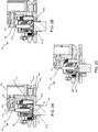
- FIGS. 1 and 2A-C show exemplary embodiments of an apparatus 100 for performing a light-absorption measurement of a specified amount of sample subject to pressure force.
- the apparatus 100 includes a surface 102 configured to receive a sample S thereon.
- the surface 102 is an upper surface of a base member 103.
- a light reflector 104 is mechanically coupled with the surface 102 and separated from the surface 102 by a separation distance. As such, the separation distance is defined as the shortest distance between the light reflector 104 and the surface 102.
- the light reflector 104 has at least one reflective surface.
- An actuator 106 is connected to at least one of the surface 102 and the light reflector 104 to change the separation distance, while the light reflector 104 remains mechanically coupled with the surface 102, to a first separation distance and to a second separation distance different from the first separation distance.
- a first stopping member 108 is arranged to stop a first change in the separation distance at the first separation distance
- a second stopping member 110 is arranged to stop a second change in the separation distance at the second separation distance.
- FIG. 1 shows an exemplary embodiment of the apparatus 100.
- FIG. 2A shows an exemplary embodiment of the apparatus 100 when the separation distance is equal to a distance D1.
- FIG. 2B shows an exemplary embodiment of the apparatus 100 when the separation distance is equal to a distance D2.
- FIG. 2C shows an exemplary embodiment of the apparatus 100 when the light reflector 104 and the surface 102 are accessible for cleaning by a user.
- the various components of the apparatus 100 are arranged to allow horizontal access to the light reflector 104, thereby facilitating cleaning of the light reflector 104 and the surface 102.
- a cam arrangement on a rotatable shaft 116 of the actuator 106 is configured such that the housing 126 is moved away from the surface 102 and the light reflector 104 projects downward from the housing.
- FIGS. 1 and 2A-C illustrate exemplary mechanical couplings between the light reflector 104 and the surface 102.
- a mechanical coupling between the light reflector 104 and the surface 102 includes a base member 103, a housing 126, a sample link member 122 having first and second ends 122A and 122B, a rotatable shaft 116 of the actuator 106, the rotatable shaft 116 having first and second cam profiles 118 and 120, and a light reflector link member 124 having first and second ends 124A and 124B.
- the surface 102 is an upper surface of the base member 103, and the base member 103 is in contact with the first end 122A of the sample link member 122.
- the second end 122B of the sample link member 122 interacts with the first cam profile 118 of the rotatable shaft 116, the rotatable shaft 116 is fixed to the housing 126 and is rotatable relative to the housing 126, and the light reflector link member 124 is fixed to the light reflector 104.
- the light reflector 104 is fixed to the second end 124B of the light reflector link member 124.
- the first end 122A of the sample link member 122 is directly attached or indirectly attached (i.e. attached via another component) to the surface 102.
- the first end 122A of the sample link member 122 and the surface 102 are arranged in any suitable manner such that as the separation distance changes, the sample link member 122 and the surface 102 do not move relative to one another.
- the sample S has a volume in a range of 1 microliter to 10 microliters, such as a volume in a range of 1 microliter to 3 microliters, but the sample S is not limited to this volume range.
- the sample S can have any suitable sample volume, which can include values smaller than 1 microliter and/or greater than 10 microliters.
- the sample S is subject to pressure force.
- pressure force can lead to compression, spreading, and/or displacement of the sample S, unlike tension force, which could lead to stretching of a sample. Stretching the sample into a column could result in a portion of the sample having a smaller diameter. This could lead to light leaking out of the sample, thereby deteriorating the measurement being performed.
- pressure force By using pressure force, the risk of light leaking out of the sample is reduced.
- the sample S is subject to pressure force by a portion of the surface 102 and/or a portion of the light reflector 104, causing the sample S to be compressed, to spread, and/or to displace.
- the mechanical coupling between the light reflector 104 and the surface 102 includes the housing 116, which contacts an upwardly-facing surface 124C of the light reflector link member 124.
- the mechanical coupling between the light reflector 104 and the surface 102 includes the second cam profile 120 of the rotatable shaft 116, which interacts with the first end 124A of the light reflector link member 124.
- the interactions between the link members and the cam profiles and/or the housing 126 can include, but are not limited to, direct or indirect (i.e. via another component) physical contact and/or magnetic attraction and/or repulsion.
- the surface 102 can be flat, curved, or of any desired shape.
- the surface 102 is a flat tray surface configured to receive a sample S.
- the first stopping member 108 is arranged to stop a first reduction in the separation distance at the first separation distance
- the second stopping member 110 arranged to stop a second reduction in the separation distance at the second separation distance.
- the first change in the separation distance is a first reduction in the separation distance
- the second change in the separation distance is a second reduction in the separation distance.
- the first and second changes in the separation distance can both be increases in the separation distance, or one can be a reduction and the other can be an increase, so long as the sample S remains subject to pressure force. By subjecting the sample S to pressure force, the sample S is less likely to be subject to ambient conditions, and is less likely to vibrate or otherwise change position.
- subjecting the sample S to pressure force can result in more desirable, repeatable, and accurate light-absorption measurements.
- a sample S placed on the surface 102 is subject to pressure force between the surface 102 and the light reflector 104 while these changes are occurring.
- the first and second stopping members allow for an open-loop operation of the apparatus 100.
- the light reflector 104 is configured to reflect ultraviolet light and visible light onto a sample S.
- the light reflector 104 can be arranged to reflect light of any suitable range or ranges of wavelength onto a sample S.
- the light reflector 104 can include or be combined with a filter than transmits or blocks light from any suitable range or ranges of wavelengths.
- the light reflector 104 can include or be combined with a material that reflects light from any suitable range or ranges of wavelengths.
- the light reflector 104 of the apparatus 100 can provide a light pathlength of at least twice the thickness of the sample S, since light originating from a source below the surface 102 is reflected by the light reflector 104 and thus travels the separation distance twice during one measurement. As a result, a smaller amount (e.g., half) of the sample S can be sufficient for a light-absorption measurement.
- An exemplary embodiment of the apparatus 100 includes a source 112 of at least one of ultraviolet light, visible light and/or infrared light.
- the source 112 can be a source of light from any suitable range or ranges of wavelengths.
- An exemplary embodiment of the apparatus 100 includes a sensor 114 disposed such that the surface 102 is disposed between the light reflector 104 and the sensor 114.
- the actuator 106 includes a rotatable shaft 116 having a first cam profile 118 at a first axial position and a second cam profile 120 at a second axial position, the rotatable shaft 116 being connected for rotation by the actuator 106.
- the cams can be mechanical cams, magnetic cams, or any suitable cam element known in the art.
- the cams provide a controlled descent of the light reflector 104 toward the sample S, thereby avoiding splashing.
- the cams also provide a controlled sequence of successive long- and short-pathlength measurements, and subsequently push out the light reflector 104 so that the light reflector 104 and the surface 102 are easily accessible for cleaning.
- An exemplary embodiment of the apparatus 100 for performing a spectroscopic measurement includes a sample link member 122 and a light reflector link member 124.
- the sample link member 122 has a first end 122A and a second end 122B.
- the first end 122A is fixedly linked to or in contact with the surface 102, and the second end 122B interacts with the first cam profile 118 of the rotatable shaft 116.
- a light reflector link member 124 has a first end 124A and a second end 124B, and the first end 124A interacts with the second cam profile 120 of the rotatable shaft 116.
- the light reflector 104 is disposed on the second end 124B of the light reflector link member 124.
- the interactions between the link members and the cam profiles can include, but are not limited to, direct or indirect physical contact and/or magnetic attraction and/or repulsion.
- the radius R1 of the first cam profile 118 of the rotatable shaft 116 at the contact point between the first cam profile 118 and the second end 122B of the sample link member 122 changes to vary a distance between the rotatable shaft 116 and the surface 102.
- this radius R1 increases (e.g., as it would from FIG. 2B to FIG. 2C )
- the distance between the shaft 116 and the sample link member 122 increases. Since the sample link member 122 is fixedly linked to or in contact with the surface 102, the distance between the surface 102 and the rotatable shaft 116 also increases.
- the radius R1 of the first cam profile 118 at the contact point decreases (e.g., from FIG. 2C to FIG. 2B )
- gravity and/or magnetic forces bring the rotatable shaft 116 down from its position shown in FIG. 2C , closer to the sample link member 122, and therefore closer to the surface 102 as shown in FIG. 2B .
- the two magnets 132 and 134 shown in FIGS 2A-C and the weight of the upper portion of the apparatus 100 bring the rotatable shaft 116 down closer to the surface 102.
- the rotatable shaft 116 and the sample link member 122 are biased toward one another such that the distance between them is reduced as the radius R1 decreases.
- a biasing element 129 reduces the distance between the shaft 116 and the sample support member 122.
- the radius R2 of the second cam profile 120 of the rotatable shaft 116 at the contact point between the second cam profile 120 and the first end 124A of the light reflector link member 124 changes to vary a distance between the rotatable shaft 116 and the light reflector 104.
- this radius R2 increases (e.g., from FIG. 2A to FIG. 2B )
- the distance between the shaft 116 and the light reflector link member 124 increases. Since the light reflector 104 is disposed on the second end 124B of the light reflector link member 124, the distance between the light reflector 104 and the rotatable shaft 116 also increases.
- a biasing element reduces the distance between the shaft 116 and the light reflector link member 124.
- a compression spring 128 disposed between a flange 1242 of the light reflector link member 124 and a ring 1262 fixed to the housing 126 biases the light reflector link member 124 from its position shown in FIG. 2B toward its position shown in FIG. 2A .
- the ring 1262 depicted in FIGS. 1 and 2A-C is attached to the housing 126 by an adjustment spring 130.
- the contact between the first stopping member 108 and the surface 102 maintains the first separation distance D1 as shown in FIG. 2A , so that a light-absorption measurement can be performed at that distance.
- the contact between the second stopping member 110 and the surface 102 maintains the second separation distance D2 as shown in FIG. 2B , so that a light-absorption measurement can be performed at that distance.
- An exemplary embodiment of the apparatus 100 includes first and second magnets 132 and 134.
- the first magnet is disposed on the base member 103
- the second magnet 134 is disposed on the housing 126.
- the first and second magnets 132 and 134 are configured to reduce the risk of an abrupt contact between the housing 126 and the base member 103 as the housing 126 is moved toward the base member 103.
- An abrupt contact could disturb the sample S and undesirably affect light-absorption measurements.
- the first and second magnets 132 and 134 do not make contact as the separation distance is changed from D1 to D2, and as the apparatus 100 is moved to a cleaning position.
- the actuator 106 can be connected to change a separation distance between the actuator 106 and the surface 102, and/or change a separation distance between the actuator 106 and the light reflector 104.
- the actuator 106 can cause any one of the surface 102, the light reflector 104, and/or the actuator 106 to be displaced relative to a user.
- the first stopping member 108 and/or the second stopping member 110 can be fixed to or integral with a particular feature of the apparatus.
- the stopping members can include one or more pins attached to the particular feature. Possible attachments between the pins and the feature include, but are not limited to, bolting, press-fitting, gluing, welding, or any other attachments known in the art.
- the stopping members can include one or more projections that are integral with the particular feature.
- the first stopping members 108 can include three pins
- the second stopping members 110 can include three projections.
- the stopping members can include any stops known in the art.
- An exemplary embodiment of the apparatus 100 includes a sample link member 122 fixedly linked to or in contact with the surface 102, and a light reflector link member 124 fixedly linked to the light reflector 104.
- the first stopping member 108 is fixed to or integral with the housing 126 and is arranged to make contact with the surface 102 or the sample link member 122 such that the separation distance will be equal to the first separation distance D1.
- the first stopping member 108 stops a relative displacement of the sample link member 122 with respect to the light reflector 104.
- the first stopping member 108 is fixedly linked to the housing 126, and stops the sample link member 122 by making contact with the sample link member 122, or alternatively any feature that is fixedly linked to the sample link member 122, including, but not limited to, the surface 102.
- the first stopping member 108 is instead fixedly linked to the surface 102.
- the second stopping member 110 is fixed to or integral with the light reflector link member 124 and is arranged to make contact with the surface 102 or the sample link member 122 such that the separation distance will be equal to the second separation distance D2.
- the second stopping member 110 stops a relative displacement of the light reflector link member 124 with respect to the surface 102.
- the second stopping member 110 is fixedly linked to the light reflector link member 124, and stops the light reflector link member 124 by making contact with the sample link member 122, or alternatively any feature that is fixedly linked to or in contact with the sample link member 122, including, but not limited to, the surface 102.
- the second stopping member 110 is instead fixedly linked to the surface 102.
- the first stopping member 108 includes pins that are fixed to the light reflector link member 124. The other end of each pin makes contact with the surface 102 or an adjacent surface to stop at the first separation distance D1 as shown in FIG. 2A .
- the second stopping member 110 includes projections on the light reflector link member 124. These projections make contact with the surface 102 or an adjacent surface to stop at the second separation distance D2 as shown in FIG. 2B .
- An exemplary embodiment of the apparatus 100 can include a power supply connected to drive the actuator 106.
- the actuator 106 can be manual.
- the actuator 106 includes a motor connected to the power supply.
- An exemplary embodiment of the apparatus 100 includes a housing 126, wherein the actuator 106 is connected to the at least one of the surface 102 and the light reflector 104 to change the separation distance while the light reflector 104 remains at least partially disposed in the housing 126 so that the light reflector 104 is protected from external disturbances.
- the light reflector 104 can be protected from a user bumping into the apparatus 100 and affecting the position and/or state of the light reflector 104.
- An exemplary embodiment of the apparatus 100 includes a housing 126 configured to shield the surface 102 from ambient conditions.
- the housing 126 can hermetically seal the surface 102 and/or the light reflector 104.
- the housing 126 can act as a shield protecting at least a portion of the surface 102 and/or the light reflector 104 from, for example, ambient particle contamination, or a user bumping into the sample.
- a housing 126 can be closed or partially open.
- the housing 126 can cover a portion or the entirety of one or more components of the apparatus 100.
- An exemplary embodiment of the apparatus 100 can be configured in combination with a sample S placed on the surface 102.
- additional stopping members can be arranged on the apparatus 100 and configured to stop the change in the separation distance between the light reflector 104 and the surface at various additional separation distance increments.
- FIG. 3 shows a block diagram of an exemplary embodiment of an apparatus 300 for performing a light-absorption measurement of a specified amount of sample subject to pressure force.
- the apparatus 300 includes a surface 102 configured to receive a sample S thereon, a light reflector 104 mechanically coupled with the surface 102 and separated from the surface 102 by a separation distance.
- An actuator 106 is connected to at least one of the surface 102 and the light reflector 104 to change the separation distance, while the light reflector 104 remains mechanically coupled with the surface 102, to a first separation distance and to a second separation distance different from the first separation distance.
- a first stopping member 108 can be arranged to stop a first change in the separation distance at the first separation distance
- a second stopping member 110 can be arranged to stop a second change in the separation distance at the second separation distance.
- the actuator 106 can be operated by any combinations of manual, electric and software operations.
- a processor can be configured to execute commands stored on non-transitory computer-readable media to control the position of the actuator 106 and/or the stopping members 108 and 110.
- additional stopping members can be arranged on the apparatus 300 and configured to stop the change in the separation distance between the light reflector 104 and the surface at various additional separation distance increments.
- the actuator 106 can be configured to stop at various separation distances.
- FIG. 4 shows a block diagram of an exemplary method 400 for performing a light-absorption measurement of a specified amount of sample S subject to pressure force.
- the method 400 includes placing the sample S on the surface 102 of an apparatus 100 including the surface 102 and a light reflector 104, the light reflector 104 being mechanically coupled with the surface 102 and separated from the surface 102 by a separation distance, at step 402.
- the method 400 includes changing the separation distance, while the light reflector 104 remains mechanically coupled with the surface 102, to a first separation distance, at step 404, and performing a first light-absorption measurement of the sample S via the apparatus 100, while the separation distance is equal to the first separation distance, and while the sample S is subject to pressure force, at step 406.
- This change in separation distance can be an increase or a reduction, so long as the sample S remains subject to pressure force.
- the sample S is less likely to be subject to ambient conditions, and is less likely to vibrate or otherwise change position.
- subjecting the sample S to pressure force can result in more desirable, repeatable, and accurate light-absorption measurements.
- the changing of the separation distance to the first separation distance includes stopping one of the surface 102 and the light reflector 104 using a first stopping member 108 such that the separation distance is equal to the first separation distance.
- An exemplary method 400 for performing a light-absorption measurement of a specified amount of sample S subject to pressure force includes changing the separation distance, while the light reflector 104 remains mechanically coupled with the surface 102, to a second separation distance different from the first separation distance, at step 408.
- the method 400 can include performing a second light-absorption measurement of the sample S via the apparatus 100, while the separation distance is equal to the second separation distance, and while the sample S is subject to pressure force, at step 410.
- This change in separation distance can be an increase or a reduction, so long as the sample S remains subject to pressure force.
- the changing of the separation distance to the second separation distance can include stopping one of the surface 102 and the light reflector 104 using a second stopping member 110 such that the separation distance is equal to the second separation distance.
Landscapes
- Physics & Mathematics (AREA)
- Health & Medical Sciences (AREA)
- Life Sciences & Earth Sciences (AREA)
- Chemical & Material Sciences (AREA)
- Analytical Chemistry (AREA)
- Biochemistry (AREA)
- General Health & Medical Sciences (AREA)
- General Physics & Mathematics (AREA)
- Immunology (AREA)
- Pathology (AREA)
- Spectroscopy & Molecular Physics (AREA)
- Investigating Or Analysing Materials By Optical Means (AREA)
- Engineering & Computer Science (AREA)
- Mathematical Physics (AREA)
- Theoretical Computer Science (AREA)
Applications Claiming Priority (2)
| Application Number | Priority Date | Filing Date | Title |
|---|---|---|---|
| US14/558,207 US9606051B2 (en) | 2014-12-02 | 2014-12-02 | Apparatus and method for performing a light-absorption measurement of a specified amount of sample subject to pressure force |
| PCT/EP2015/077248 WO2016087236A1 (en) | 2014-12-02 | 2015-11-20 | Apparatus and method for performing a light-absorption measurement of a specified amount of sample subject to pressure force |
Publications (2)
| Publication Number | Publication Date |
|---|---|
| EP3227665A1 EP3227665A1 (en) | 2017-10-11 |
| EP3227665B1 true EP3227665B1 (en) | 2019-04-17 |
Family
ID=54608538
Family Applications (1)
| Application Number | Title | Priority Date | Filing Date |
|---|---|---|---|
| EP15797676.2A Active EP3227665B1 (en) | 2014-12-02 | 2015-11-20 | Apparatus and method for performing a light-absorption measurement of a specified amount of sample subject to pressure force |
Country Status (5)
| Country | Link |
|---|---|
| US (1) | US9606051B2 (zh) |
| EP (1) | EP3227665B1 (zh) |
| JP (1) | JP6693956B2 (zh) |
| CN (1) | CN107003235B (zh) |
| WO (1) | WO2016087236A1 (zh) |
Families Citing this family (2)
| Publication number | Priority date | Publication date | Assignee | Title |
|---|---|---|---|---|
| US9778185B2 (en) * | 2015-10-27 | 2017-10-03 | Laxco Incorporated | Analytical instrument with collimated and adjustable length optical path |
| US12019014B2 (en) * | 2021-07-16 | 2024-06-25 | Thermo Electron Scientific Instruments Llc | Method and apparatus for determining a force applied to a sample during an optical interrogation technique |
Family Cites Families (20)
| Publication number | Priority date | Publication date | Assignee | Title |
|---|---|---|---|---|
| US4934816A (en) * | 1988-05-18 | 1990-06-19 | Southwest Sciences, Incorporated | Laser absorption detection enhancing apparatus and method |
| JPH02236147A (ja) | 1989-03-09 | 1990-09-19 | Suzuki Motor Co Ltd | オイル劣化検出装置 |
| US5739432A (en) * | 1996-05-30 | 1998-04-14 | The Regents Of The University Of California | Ultrasonic characterization of single drops of liquids |
| US6496260B1 (en) * | 1998-12-23 | 2002-12-17 | Molecular Devices Corp. | Vertical-beam photometer for determination of light absorption pathlength |
| WO2001014855A1 (en) | 1999-08-20 | 2001-03-01 | Charles William Robertson | Liquid photometer using surface tension to contain sample |
| DE102004023178B4 (de) * | 2004-05-07 | 2006-06-29 | Hellma Gmbh & Co. Kg | Vorrichtung für die Analyse oder Absorptionsmessung an einer kleinen Menge eines flüssigen Mediums mit Hilfe von Licht |
| US7902534B2 (en) * | 2004-09-28 | 2011-03-08 | Honeywell International Inc. | Cavity ring down system having a common input/output port |
| US7375815B2 (en) | 2004-10-12 | 2008-05-20 | Agilent Technologies, Inc. | Optical devices, systems and method for producing a collimated light path |
| US7259856B2 (en) * | 2005-02-16 | 2007-08-21 | Picarro, Inc. | Method for the precise measurement of the wavelength of light |
| DE102005036898B4 (de) | 2005-08-05 | 2008-01-10 | Hellma Gmbh & Co. Kg | Vorrichtung für die Analyse oder Absorptionsmessung an einer kleinen Flüssigkeitsmenge |
| GB0520207D0 (en) | 2005-10-05 | 2005-11-09 | Smiths Group Plc | Optical sampling arrangements |
| PL1792653T3 (pl) * | 2005-12-05 | 2008-05-30 | Foss Analytical As | Urządzenie i sposób do analizy spektrofotometrycznej |
| CN101523191B (zh) * | 2006-10-06 | 2012-06-06 | 株式会社岛津制作所 | 分光光度计 |
| CN102232181B (zh) | 2008-10-03 | 2014-09-17 | 纳诺多普科技有限责任公司 | 双采样模式的分光光度计 |
| EP2342549B1 (en) * | 2008-10-03 | 2014-06-04 | NanoDrop Technologies LLC | Optical path length sensor and method for optimal absorbance measurements |
| JP5669449B2 (ja) | 2009-06-26 | 2015-02-12 | メトラー−トレド アクチェンゲゼルシャフト | 屈折計 |
| CN102042961B (zh) | 2009-10-20 | 2013-03-27 | 博奥生物有限公司 | 一种光纤反射式微纳体系分光光度计及其应用 |
| EP2585814A1 (en) * | 2010-06-23 | 2013-05-01 | Commonwealth Scientific and Industrial Research Organisation | An absorption probe for measuring dissolved organic carbon in an aqueous sample |
| DE102010048651B3 (de) | 2010-10-15 | 2012-03-22 | Berthold Detection Systems Gmbh | Vorrichtung zur photometrischen Untersuchung einer Flüssigkeitsprobe |
| WO2012135044A1 (en) * | 2011-03-25 | 2012-10-04 | University Of Virginia Patent Foundation | Adaptable cell design for a spectroscopy apparatus |
-
2014
- 2014-12-02 US US14/558,207 patent/US9606051B2/en active Active
-
2015
- 2015-11-20 WO PCT/EP2015/077248 patent/WO2016087236A1/en active Application Filing
- 2015-11-20 EP EP15797676.2A patent/EP3227665B1/en active Active
- 2015-11-20 JP JP2017529337A patent/JP6693956B2/ja active Active
- 2015-11-20 CN CN201580062482.6A patent/CN107003235B/zh active Active
Non-Patent Citations (1)
| Title |
|---|
| None * |
Also Published As
| Publication number | Publication date |
|---|---|
| CN107003235A (zh) | 2017-08-01 |
| JP2018501476A (ja) | 2018-01-18 |
| US20160153895A1 (en) | 2016-06-02 |
| US9606051B2 (en) | 2017-03-28 |
| CN107003235B (zh) | 2020-09-04 |
| EP3227665A1 (en) | 2017-10-11 |
| JP6693956B2 (ja) | 2020-05-13 |
| WO2016087236A1 (en) | 2016-06-09 |
Similar Documents
| Publication | Publication Date | Title |
|---|---|---|
| EP2071317B1 (en) | Spectrophotometer | |
| US10551303B2 (en) | Flow cell optical detection system | |
| KR102318409B1 (ko) | 곡선부를 특징짓는 프리즘-커플링 시스템 및 방법 | |
| JP6351180B2 (ja) | 分光測定用電動光路長可変セル | |
| CN108955878B (zh) | 具有欠充满光纤样品接口的光学分光计 | |
| KR100621315B1 (ko) | 렌즈미터 | |
| US6476908B1 (en) | Optical probe | |
| EP3227665B1 (en) | Apparatus and method for performing a light-absorption measurement of a specified amount of sample subject to pressure force | |
| MX2012006523A (es) | Sonda de longitud de trayectoria variable. | |
| KR20200123001A (ko) | 광학 분석 장치 | |
| EP3039404B1 (en) | Improved motorized variable path length cell for spectroscopy | |
| US11486865B2 (en) | Systems for a modular multi-wavelength absorbance detector | |
| EP2713147B1 (en) | Optical detection instrument comprising triggering device | |
| KR102488587B1 (ko) | 광학 측정 장치 및 광학 측정 방법 | |
| KR102426076B1 (ko) | 자외선 감지용 광섬유 센서 모듈 및 이를 이용한 자외선 측정 장치 | |
| US20230077547A1 (en) | Apparatuses, systems, and methods for sample testing | |
| JPH1010042A (ja) | 赤外顕微鏡 |
Legal Events
| Date | Code | Title | Description |
|---|---|---|---|
| STAA | Information on the status of an ep patent application or granted ep patent |
Free format text: STATUS: THE INTERNATIONAL PUBLICATION HAS BEEN MADE |
|
| PUAI | Public reference made under article 153(3) epc to a published international application that has entered the european phase |
Free format text: ORIGINAL CODE: 0009012 |
|
| STAA | Information on the status of an ep patent application or granted ep patent |
Free format text: STATUS: REQUEST FOR EXAMINATION WAS MADE |
|
| 17P | Request for examination filed |
Effective date: 20170613 |
|
| AK | Designated contracting states |
Kind code of ref document: A1 Designated state(s): AL AT BE BG CH CY CZ DE DK EE ES FI FR GB GR HR HU IE IS IT LI LT LU LV MC MK MT NL NO PL PT RO RS SE SI SK SM TR |
|
| AX | Request for extension of the european patent |
Extension state: BA ME |
|
| DAV | Request for validation of the european patent (deleted) | ||
| DAX | Request for extension of the european patent (deleted) | ||
| GRAP | Despatch of communication of intention to grant a patent |
Free format text: ORIGINAL CODE: EPIDOSNIGR1 |
|
| STAA | Information on the status of an ep patent application or granted ep patent |
Free format text: STATUS: GRANT OF PATENT IS INTENDED |
|
| RIC1 | Information provided on ipc code assigned before grant |
Ipc: G01N 21/01 20060101AFI20180607BHEP Ipc: G01N 21/03 20060101ALI20180607BHEP Ipc: G01N 21/25 20060101ALI20180607BHEP |
|
| INTG | Intention to grant announced |
Effective date: 20180703 |
|
| GRAJ | Information related to disapproval of communication of intention to grant by the applicant or resumption of examination proceedings by the epo deleted |
Free format text: ORIGINAL CODE: EPIDOSDIGR1 |
|
| STAA | Information on the status of an ep patent application or granted ep patent |
Free format text: STATUS: REQUEST FOR EXAMINATION WAS MADE |
|
| GRAP | Despatch of communication of intention to grant a patent |
Free format text: ORIGINAL CODE: EPIDOSNIGR1 |
|
| STAA | Information on the status of an ep patent application or granted ep patent |
Free format text: STATUS: GRANT OF PATENT IS INTENDED |
|
| INTC | Intention to grant announced (deleted) | ||
| INTG | Intention to grant announced |
Effective date: 20181116 |
|
| GRAS | Grant fee paid |
Free format text: ORIGINAL CODE: EPIDOSNIGR3 |
|
| GRAA | (expected) grant |
Free format text: ORIGINAL CODE: 0009210 |
|
| STAA | Information on the status of an ep patent application or granted ep patent |
Free format text: STATUS: THE PATENT HAS BEEN GRANTED |
|
| AK | Designated contracting states |
Kind code of ref document: B1 Designated state(s): AL AT BE BG CH CY CZ DE DK EE ES FI FR GB GR HR HU IE IS IT LI LT LU LV MC MK MT NL NO PL PT RO RS SE SI SK SM TR |
|
| REG | Reference to a national code |
Ref country code: GB Ref legal event code: FG4D |
|
| REG | Reference to a national code |
Ref country code: CH Ref legal event code: EP |
|
| REG | Reference to a national code |
Ref country code: DE Ref legal event code: R096 Ref document number: 602015028564 Country of ref document: DE |
|
| REG | Reference to a national code |
Ref country code: AT Ref legal event code: REF Ref document number: 1122105 Country of ref document: AT Kind code of ref document: T Effective date: 20190515 Ref country code: IE Ref legal event code: FG4D |
|
| REG | Reference to a national code |
Ref country code: NL Ref legal event code: MP Effective date: 20190417 |
|
| REG | Reference to a national code |
Ref country code: LT Ref legal event code: MG4D |
|
| PG25 | Lapsed in a contracting state [announced via postgrant information from national office to epo] |
Ref country code: NL Free format text: LAPSE BECAUSE OF FAILURE TO SUBMIT A TRANSLATION OF THE DESCRIPTION OR TO PAY THE FEE WITHIN THE PRESCRIBED TIME-LIMIT Effective date: 20190417 |
|
| PG25 | Lapsed in a contracting state [announced via postgrant information from national office to epo] |
Ref country code: PT Free format text: LAPSE BECAUSE OF FAILURE TO SUBMIT A TRANSLATION OF THE DESCRIPTION OR TO PAY THE FEE WITHIN THE PRESCRIBED TIME-LIMIT Effective date: 20190817 Ref country code: NO Free format text: LAPSE BECAUSE OF FAILURE TO SUBMIT A TRANSLATION OF THE DESCRIPTION OR TO PAY THE FEE WITHIN THE PRESCRIBED TIME-LIMIT Effective date: 20190717 Ref country code: FI Free format text: LAPSE BECAUSE OF FAILURE TO SUBMIT A TRANSLATION OF THE DESCRIPTION OR TO PAY THE FEE WITHIN THE PRESCRIBED TIME-LIMIT Effective date: 20190417 Ref country code: SE Free format text: LAPSE BECAUSE OF FAILURE TO SUBMIT A TRANSLATION OF THE DESCRIPTION OR TO PAY THE FEE WITHIN THE PRESCRIBED TIME-LIMIT Effective date: 20190417 Ref country code: AL Free format text: LAPSE BECAUSE OF FAILURE TO SUBMIT A TRANSLATION OF THE DESCRIPTION OR TO PAY THE FEE WITHIN THE PRESCRIBED TIME-LIMIT Effective date: 20190417 Ref country code: HR Free format text: LAPSE BECAUSE OF FAILURE TO SUBMIT A TRANSLATION OF THE DESCRIPTION OR TO PAY THE FEE WITHIN THE PRESCRIBED TIME-LIMIT Effective date: 20190417 Ref country code: ES Free format text: LAPSE BECAUSE OF FAILURE TO SUBMIT A TRANSLATION OF THE DESCRIPTION OR TO PAY THE FEE WITHIN THE PRESCRIBED TIME-LIMIT Effective date: 20190417 Ref country code: LT Free format text: LAPSE BECAUSE OF FAILURE TO SUBMIT A TRANSLATION OF THE DESCRIPTION OR TO PAY THE FEE WITHIN THE PRESCRIBED TIME-LIMIT Effective date: 20190417 |
|
| PG25 | Lapsed in a contracting state [announced via postgrant information from national office to epo] |
Ref country code: LV Free format text: LAPSE BECAUSE OF FAILURE TO SUBMIT A TRANSLATION OF THE DESCRIPTION OR TO PAY THE FEE WITHIN THE PRESCRIBED TIME-LIMIT Effective date: 20190417 Ref country code: RS Free format text: LAPSE BECAUSE OF FAILURE TO SUBMIT A TRANSLATION OF THE DESCRIPTION OR TO PAY THE FEE WITHIN THE PRESCRIBED TIME-LIMIT Effective date: 20190417 Ref country code: BG Free format text: LAPSE BECAUSE OF FAILURE TO SUBMIT A TRANSLATION OF THE DESCRIPTION OR TO PAY THE FEE WITHIN THE PRESCRIBED TIME-LIMIT Effective date: 20190717 Ref country code: PL Free format text: LAPSE BECAUSE OF FAILURE TO SUBMIT A TRANSLATION OF THE DESCRIPTION OR TO PAY THE FEE WITHIN THE PRESCRIBED TIME-LIMIT Effective date: 20190417 Ref country code: GR Free format text: LAPSE BECAUSE OF FAILURE TO SUBMIT A TRANSLATION OF THE DESCRIPTION OR TO PAY THE FEE WITHIN THE PRESCRIBED TIME-LIMIT Effective date: 20190718 |
|
| REG | Reference to a national code |
Ref country code: AT Ref legal event code: MK05 Ref document number: 1122105 Country of ref document: AT Kind code of ref document: T Effective date: 20190417 |
|
| PG25 | Lapsed in a contracting state [announced via postgrant information from national office to epo] |
Ref country code: IS Free format text: LAPSE BECAUSE OF FAILURE TO SUBMIT A TRANSLATION OF THE DESCRIPTION OR TO PAY THE FEE WITHIN THE PRESCRIBED TIME-LIMIT Effective date: 20190817 |
|
| REG | Reference to a national code |
Ref country code: DE Ref legal event code: R097 Ref document number: 602015028564 Country of ref document: DE |
|
| PG25 | Lapsed in a contracting state [announced via postgrant information from national office to epo] |
Ref country code: CZ Free format text: LAPSE BECAUSE OF FAILURE TO SUBMIT A TRANSLATION OF THE DESCRIPTION OR TO PAY THE FEE WITHIN THE PRESCRIBED TIME-LIMIT Effective date: 20190417 Ref country code: RO Free format text: LAPSE BECAUSE OF FAILURE TO SUBMIT A TRANSLATION OF THE DESCRIPTION OR TO PAY THE FEE WITHIN THE PRESCRIBED TIME-LIMIT Effective date: 20190417 Ref country code: AT Free format text: LAPSE BECAUSE OF FAILURE TO SUBMIT A TRANSLATION OF THE DESCRIPTION OR TO PAY THE FEE WITHIN THE PRESCRIBED TIME-LIMIT Effective date: 20190417 Ref country code: DK Free format text: LAPSE BECAUSE OF FAILURE TO SUBMIT A TRANSLATION OF THE DESCRIPTION OR TO PAY THE FEE WITHIN THE PRESCRIBED TIME-LIMIT Effective date: 20190417 Ref country code: EE Free format text: LAPSE BECAUSE OF FAILURE TO SUBMIT A TRANSLATION OF THE DESCRIPTION OR TO PAY THE FEE WITHIN THE PRESCRIBED TIME-LIMIT Effective date: 20190417 Ref country code: SK Free format text: LAPSE BECAUSE OF FAILURE TO SUBMIT A TRANSLATION OF THE DESCRIPTION OR TO PAY THE FEE WITHIN THE PRESCRIBED TIME-LIMIT Effective date: 20190417 |
|
| PLBE | No opposition filed within time limit |
Free format text: ORIGINAL CODE: 0009261 |
|
| STAA | Information on the status of an ep patent application or granted ep patent |
Free format text: STATUS: NO OPPOSITION FILED WITHIN TIME LIMIT |
|
| PG25 | Lapsed in a contracting state [announced via postgrant information from national office to epo] |
Ref country code: IT Free format text: LAPSE BECAUSE OF FAILURE TO SUBMIT A TRANSLATION OF THE DESCRIPTION OR TO PAY THE FEE WITHIN THE PRESCRIBED TIME-LIMIT Effective date: 20190417 Ref country code: SM Free format text: LAPSE BECAUSE OF FAILURE TO SUBMIT A TRANSLATION OF THE DESCRIPTION OR TO PAY THE FEE WITHIN THE PRESCRIBED TIME-LIMIT Effective date: 20190417 |
|
| 26N | No opposition filed |
Effective date: 20200120 |
|
| PG25 | Lapsed in a contracting state [announced via postgrant information from national office to epo] |
Ref country code: TR Free format text: LAPSE BECAUSE OF FAILURE TO SUBMIT A TRANSLATION OF THE DESCRIPTION OR TO PAY THE FEE WITHIN THE PRESCRIBED TIME-LIMIT Effective date: 20190417 |
|
| PG25 | Lapsed in a contracting state [announced via postgrant information from national office to epo] |
Ref country code: SI Free format text: LAPSE BECAUSE OF FAILURE TO SUBMIT A TRANSLATION OF THE DESCRIPTION OR TO PAY THE FEE WITHIN THE PRESCRIBED TIME-LIMIT Effective date: 20190417 |
|
| PG25 | Lapsed in a contracting state [announced via postgrant information from national office to epo] |
Ref country code: LU Free format text: LAPSE BECAUSE OF NON-PAYMENT OF DUE FEES Effective date: 20191120 Ref country code: MC Free format text: LAPSE BECAUSE OF FAILURE TO SUBMIT A TRANSLATION OF THE DESCRIPTION OR TO PAY THE FEE WITHIN THE PRESCRIBED TIME-LIMIT Effective date: 20190417 |
|
| REG | Reference to a national code |
Ref country code: BE Ref legal event code: MM Effective date: 20191130 |
|
| PG25 | Lapsed in a contracting state [announced via postgrant information from national office to epo] |
Ref country code: IE Free format text: LAPSE BECAUSE OF NON-PAYMENT OF DUE FEES Effective date: 20191120 |
|
| PG25 | Lapsed in a contracting state [announced via postgrant information from national office to epo] |
Ref country code: BE Free format text: LAPSE BECAUSE OF NON-PAYMENT OF DUE FEES Effective date: 20191130 |
|
| PG25 | Lapsed in a contracting state [announced via postgrant information from national office to epo] |
Ref country code: CY Free format text: LAPSE BECAUSE OF FAILURE TO SUBMIT A TRANSLATION OF THE DESCRIPTION OR TO PAY THE FEE WITHIN THE PRESCRIBED TIME-LIMIT Effective date: 20190417 |
|
| PG25 | Lapsed in a contracting state [announced via postgrant information from national office to epo] |
Ref country code: MT Free format text: LAPSE BECAUSE OF FAILURE TO SUBMIT A TRANSLATION OF THE DESCRIPTION OR TO PAY THE FEE WITHIN THE PRESCRIBED TIME-LIMIT Effective date: 20190417 Ref country code: HU Free format text: LAPSE BECAUSE OF FAILURE TO SUBMIT A TRANSLATION OF THE DESCRIPTION OR TO PAY THE FEE WITHIN THE PRESCRIBED TIME-LIMIT; INVALID AB INITIO Effective date: 20151120 |
|
| PG25 | Lapsed in a contracting state [announced via postgrant information from national office to epo] |
Ref country code: MK Free format text: LAPSE BECAUSE OF FAILURE TO SUBMIT A TRANSLATION OF THE DESCRIPTION OR TO PAY THE FEE WITHIN THE PRESCRIBED TIME-LIMIT Effective date: 20190417 |
|
| PGFP | Annual fee paid to national office [announced via postgrant information from national office to epo] |
Ref country code: GB Payment date: 20231121 Year of fee payment: 9 |
|
| PGFP | Annual fee paid to national office [announced via postgrant information from national office to epo] |
Ref country code: FR Payment date: 20231123 Year of fee payment: 9 Ref country code: DE Payment date: 20231127 Year of fee payment: 9 Ref country code: CH Payment date: 20231201 Year of fee payment: 9 |