EP3227569B1 - Schwenkbarer aufhänger - Google Patents
Schwenkbarer aufhänger Download PDFInfo
- Publication number
- EP3227569B1 EP3227569B1 EP15865313.9A EP15865313A EP3227569B1 EP 3227569 B1 EP3227569 B1 EP 3227569B1 EP 15865313 A EP15865313 A EP 15865313A EP 3227569 B1 EP3227569 B1 EP 3227569B1
- Authority
- EP
- European Patent Office
- Prior art keywords
- swivel
- anchor
- tool
- swivel member
- anchor head
- Prior art date
- Legal status (The legal status is an assumption and is not a legal conclusion. Google has not performed a legal analysis and makes no representation as to the accuracy of the status listed.)
- Active
Links
Images





Classifications
-
- F—MECHANICAL ENGINEERING; LIGHTING; HEATING; WEAPONS; BLASTING
- F16—ENGINEERING ELEMENTS AND UNITS; GENERAL MEASURES FOR PRODUCING AND MAINTAINING EFFECTIVE FUNCTIONING OF MACHINES OR INSTALLATIONS; THERMAL INSULATION IN GENERAL
- F16C—SHAFTS; FLEXIBLE SHAFTS; ELEMENTS OR CRANKSHAFT MECHANISMS; ROTARY BODIES OTHER THAN GEARING ELEMENTS; BEARINGS
- F16C11/00—Pivots; Pivotal connections
- F16C11/04—Pivotal connections
- F16C11/06—Ball-joints; Other joints having more than one degree of angular freedom, i.e. universal joints
-
- F—MECHANICAL ENGINEERING; LIGHTING; HEATING; WEAPONS; BLASTING
- F16—ENGINEERING ELEMENTS AND UNITS; GENERAL MEASURES FOR PRODUCING AND MAINTAINING EFFECTIVE FUNCTIONING OF MACHINES OR INSTALLATIONS; THERMAL INSULATION IN GENERAL
- F16B—DEVICES FOR FASTENING OR SECURING CONSTRUCTIONAL ELEMENTS OR MACHINE PARTS TOGETHER, e.g. NAILS, BOLTS, CIRCLIPS, CLAMPS, CLIPS OR WEDGES; JOINTS OR JOINTING
- F16B25/00—Screws that cut thread in the body into which they are screwed, e.g. wood screws
- F16B25/10—Screws performing an additional function to thread-forming, e.g. drill screws or self-piercing screws
- F16B25/103—Screws performing an additional function to thread-forming, e.g. drill screws or self-piercing screws by means of a drilling screw-point, i.e. with a cutting and material removing action
-
- F—MECHANICAL ENGINEERING; LIGHTING; HEATING; WEAPONS; BLASTING
- F16—ENGINEERING ELEMENTS AND UNITS; GENERAL MEASURES FOR PRODUCING AND MAINTAINING EFFECTIVE FUNCTIONING OF MACHINES OR INSTALLATIONS; THERMAL INSULATION IN GENERAL
- F16B—DEVICES FOR FASTENING OR SECURING CONSTRUCTIONAL ELEMENTS OR MACHINE PARTS TOGETHER, e.g. NAILS, BOLTS, CIRCLIPS, CLAMPS, CLIPS OR WEDGES; JOINTS OR JOINTING
- F16B25/00—Screws that cut thread in the body into which they are screwed, e.g. wood screws
- F16B25/001—Screws that cut thread in the body into which they are screwed, e.g. wood screws characterised by the material of the body into which the screw is screwed
- F16B25/0031—Screws that cut thread in the body into which they are screwed, e.g. wood screws characterised by the material of the body into which the screw is screwed the screw being designed to be screwed into different materials, e.g. a layered structure or through metallic and wooden parts
-
- F—MECHANICAL ENGINEERING; LIGHTING; HEATING; WEAPONS; BLASTING
- F16—ENGINEERING ELEMENTS AND UNITS; GENERAL MEASURES FOR PRODUCING AND MAINTAINING EFFECTIVE FUNCTIONING OF MACHINES OR INSTALLATIONS; THERMAL INSULATION IN GENERAL
- F16B—DEVICES FOR FASTENING OR SECURING CONSTRUCTIONAL ELEMENTS OR MACHINE PARTS TOGETHER, e.g. NAILS, BOLTS, CIRCLIPS, CLAMPS, CLIPS OR WEDGES; JOINTS OR JOINTING
- F16B35/00—Screw-bolts; Stay-bolts; Screw-threaded studs; Screws; Set screws
- F16B35/04—Screw-bolts; Stay-bolts; Screw-threaded studs; Screws; Set screws with specially-shaped head or shaft in order to fix the bolt on or in an object
- F16B35/06—Specially-shaped heads
-
- F—MECHANICAL ENGINEERING; LIGHTING; HEATING; WEAPONS; BLASTING
- F16—ENGINEERING ELEMENTS AND UNITS; GENERAL MEASURES FOR PRODUCING AND MAINTAINING EFFECTIVE FUNCTIONING OF MACHINES OR INSTALLATIONS; THERMAL INSULATION IN GENERAL
- F16M—FRAMES, CASINGS OR BEDS OF ENGINES, MACHINES OR APPARATUS, NOT SPECIFIC TO ENGINES, MACHINES OR APPARATUS PROVIDED FOR ELSEWHERE; STANDS; SUPPORTS
- F16M13/00—Other supports for positioning apparatus or articles; Means for steadying hand-held apparatus or articles
- F16M13/02—Other supports for positioning apparatus or articles; Means for steadying hand-held apparatus or articles for supporting on, or attaching to, an object, e.g. tree, gate, window-frame, cycle
- F16M13/027—Ceiling supports
-
- F—MECHANICAL ENGINEERING; LIGHTING; HEATING; WEAPONS; BLASTING
- F16—ENGINEERING ELEMENTS AND UNITS; GENERAL MEASURES FOR PRODUCING AND MAINTAINING EFFECTIVE FUNCTIONING OF MACHINES OR INSTALLATIONS; THERMAL INSULATION IN GENERAL
- F16C—SHAFTS; FLEXIBLE SHAFTS; ELEMENTS OR CRANKSHAFT MECHANISMS; ROTARY BODIES OTHER THAN GEARING ELEMENTS; BEARINGS
- F16C11/00—Pivots; Pivotal connections
- F16C11/04—Pivotal connections
- F16C11/06—Ball-joints; Other joints having more than one degree of angular freedom, i.e. universal joints
- F16C11/0604—Construction of the male part
-
- F—MECHANICAL ENGINEERING; LIGHTING; HEATING; WEAPONS; BLASTING
- F16—ENGINEERING ELEMENTS AND UNITS; GENERAL MEASURES FOR PRODUCING AND MAINTAINING EFFECTIVE FUNCTIONING OF MACHINES OR INSTALLATIONS; THERMAL INSULATION IN GENERAL
- F16C—SHAFTS; FLEXIBLE SHAFTS; ELEMENTS OR CRANKSHAFT MECHANISMS; ROTARY BODIES OTHER THAN GEARING ELEMENTS; BEARINGS
- F16C11/00—Pivots; Pivotal connections
- F16C11/04—Pivotal connections
- F16C11/06—Ball-joints; Other joints having more than one degree of angular freedom, i.e. universal joints
- F16C11/0619—Ball-joints; Other joints having more than one degree of angular freedom, i.e. universal joints the female part comprising a blind socket receiving the male part
- F16C11/0623—Construction or details of the socket member
-
- Y—GENERAL TAGGING OF NEW TECHNOLOGICAL DEVELOPMENTS; GENERAL TAGGING OF CROSS-SECTIONAL TECHNOLOGIES SPANNING OVER SEVERAL SECTIONS OF THE IPC; TECHNICAL SUBJECTS COVERED BY FORMER USPC CROSS-REFERENCE ART COLLECTIONS [XRACs] AND DIGESTS
- Y10—TECHNICAL SUBJECTS COVERED BY FORMER USPC
- Y10T—TECHNICAL SUBJECTS COVERED BY FORMER US CLASSIFICATION
- Y10T403/00—Joints and connections
- Y10T403/32—Articulated members
- Y10T403/32114—Articulated members including static joint
- Y10T403/32196—Articulate joint is ball and socket
- Y10T403/32204—Articulate joint is ball and socket with threaded joint
Definitions
- the present invention is directed toward a swivel hanger for hanging items from support surfaces.
- Fastening hardware is used to hang objects (for example, wall art, shelving structure, etc.) from support surfaces such as walls and ceilings of rooms.
- Fastening hardware that includes a swivel component is particularly useful, for example, to allow an object to be movably suspended from a support surface.
- swivel hangers There are many different types of swivel hangers, some including a number of components to facilitate a swivel connection between anchoring structure and an item to be supported by the swivel hanger.
- a swivel hanger having few components and that is easy to install would be useful for hanging household objects.
- US2008/0213034A1 relates to a swivel fitting attachment apparatus.
- DE20005059U1 relates to a fixing device.
- US2003/0190211A1 relates to a mushrooming expandable anchor.
- a swivel hanger system includes a swivel member 4 and an anchor member 20, where the swivel member 4 is suitably dimensioned and configured to rotatably couple with the anchor member 20 during system use.
- an anchoring tool 40 which may or may not be part of the system 2, is utilized to secure the anchor member 20 with swivel member 4 to a suitable support member 50.
- the swivel member 4, anchor member 20 and tool 40 can be constructed of any suitable and sufficiently rigid materials to facilitate installation and use of the anchor system, where some non-limiting examples of suitable materials include metal materials (for example, steels or steel alloys, such as stainless steel, carbon steel, etc.) and rigid plastic materials (for example, polyester resins).
- suitable materials include metal materials (for example, steels or steel alloys, such as stainless steel, carbon steel, etc.) and rigid plastic materials (for example, polyester resins).
- the anchor member 20 of the system 2 includes a threaded elongated main body portion 28 that terminates at a pointed or lower first end 24 to facilitate engagement and anchoring of the main body portion 28 within an opening or bore 52 formed in a support member 50 by rotation or screwing of the main body portion 28 into the bore 52.
- the anchor member 20 can further be configured to form the bore 52 within support member 50 as the anchor member 20 is moved toward and into the support member 50 during installation.
- the anchor member 20 is configured such that the pointed first end 24 pierces a support member 50 to create a pilot hole in the surface, where the threaded main body portion 28 is then rotated while force is applied to the anchor member 20 to force the anchor member into the support member 50, thus forming the bore 52 (where the bore becomes threaded as the anchor member is rotated into the support member 50 ) .
- the bore 52 may be initially formed by a pilot hole (a hole formed in the support member 50 having a smaller diameter or cross-sectional dimension in relation to the diameter or cross-sectional dimension of the main body portion 28 ) .
- the body portion of the anchor member 20 can also be configured to secure to the support member 50 in any other suitable manner instead of utilizing a threaded surface for a screw-like anchoring engagement.
- the body portion of the anchor member can instead have a smooth outer periphery that terminates at a point (for example, configured like a nail) to facilitate pounding of the anchor member (e.g., utilizing a hammer or other tool) into the bore 52.
- Other alternative configurations of the body portion of the anchor member can also be implemented to suitably secure the body portion within the bore 52 of the support member 50.
- the main body portion 28 also includes an upper or second end 26 that opposes the lower or first end 24.
- a flange is defined at the second end 26 (also referred to herein as the flange end 26 ) that has a cross-sectional dimension that is greater than the cross-sectional dimension of the rest of the main body portion 28, such that the flange end abuts a surface 51 of the support member 50 when the rest of the threaded main body portion 28 is secured within the bore 52.
- An anchor head 22 extends from the flange end 26.
- a column or pillar member 25 extends between the anchor head 22 from the flange end 26.
- the pillar member 25 can have a cross-sectional dimension that is less than the cross-sectional dimension of each of the anchor head 22 and flange end 26 of the main body portion 28.
- the anchor head 22 includes a flat upper surface including a patterned or shaped depression or indentation 23.
- the patterned indentation 23 can be in the shape of a six pointed star as shown in the figures.
- the indentation can also have any other suitable pattern (for example, a linear or slotted indentation, a cross or X-shaped/Phillips type indentation, etc.).
- the underside of the anchor head 22 extending from its flat upper surface to the pillar member 25 has a curved configuration that is generally hemispherical in shape (i.e., has the general shape of a cut-in-half sphere).
- the swivel member 4 is hollow and includes a rounded lower or first end 8 that has a contour generally conforming to the hemispherical underside of the anchor head 22 and further includes an opening that extends to the hollow interior of the swivel member.
- the swivel member 4 further includes a flat upper or second end 6 that includes an opening to the hollow interior of the swivel member.
- the lower or first end 8 of the swivel member 4 further includes a rotation slot or cut-out section 12 that extends from the opening at the first end 8 a selected distance along the lengthwise dimension of the swivel member 4.
- the cut-out section 12 and opening at the first end 8 are both suitably dimensioned to receive the anchor head 22 of the anchor member 20 within the hollow interior of the swivel member 4 such that the swivel member is movably secured to the anchor member, where the swivel member 4 is free to pivot or swivel about the anchor head 22 (i.e., swivel movement refers to vertical and/or horizontal rotational movements) in various directions and at various angles of in relation to the anchor member 20.
- swivel movement refers to vertical and/or horizontal rotational movements
- the relationship between anchor head 22 and first end 8 of swivel member 4 can also be described as a ball and socket respectively, where first end 8 forms an interior socket.
- Receipt of tool 40 into anchor head 22 within the hollow interior at the first end 8 of the swivel member 4 can be made possible, for example, by first aligning the swivel member 4 such that its lengthwise dimension is transverse the lengthwise dimension of the anchor member 20 and then fitting the anchor head 22 through the cut-out section 12 such that the anchor head is located within the hollow interior of the swivel member 4 at the first end 8.
- the anchor head 22 is fit inside the swivel member 4 in this manner (and as depicted in the figures), the hemispherical contour of the anchor head 22 engages with the interior rounded first end 8 of the swivel member 4 in a manner similar to a ball-and-socket type joint.
- This engagement facilitates pivotal or swiveling movement of the swivel member 4 in a variety of positions in relation to the anchor member 20 while maintaining the coupling of the swivel and anchor members via the anchor head being trapped within the swivel member hollow interior.
- the swivel member 4 further includes a threaded interior surface 10 within its hollow interior at a location proximate the upper or second end 6.
- the threaded interior surface 10 provides a connection for an object to be hung from the swivel member (for example, via connection with a threaded connector having a diameter that matches the inner diameter dimension of the threaded interior surface) when the anchor member 20 is secured with a support member 50.
- Threaded interior surface 10 may be stepped threaded so that surface 10 is replaced by multiple threads surfaces of different diameters with threads increasing in size from end 8 to end 6 enabling surface 10 to receive multiple size threaded connectors (e.g., threaded rods).
- the hollow interior of the swivel member 4 is further suitably dimensioned to facilitate insertion of at least a portion of the tool 40 lengthwise into the hollow interior via the opening at the upper of second end 6 such that tool 40 can engage with the anchor head 22 during installation as described herein.
- the tool 40 has an elongated configuration including a lower or first end 44 and an upper or second end 42 that opposes the first end 44.
- the tool 40 further has a main body portion 45 with a multi-faceted or shaped exterior periphery having a polygonal cross-section (for example, a hexagonal cross-section as shown in the figures).
- a grip or handle member such as a screw driver handle or powered tool such as a drill (not shown)
- the external periphery of the tool can be of any suitable shape (for example, circular or rounded, polygonal, irregular, etc.) that facilitates a releasable coupling or complementary shaped connection between the tool and handle member or powered tool.
- the lower or first end 44 of the tool 40 can have a reduced cross-sectional dimension in relation to the tool main body portion 45 and further has a cross-sectional geometric shape that corresponds with the indentation 23 of the anchor head 22.
- the first end 44 can have a six pointed star-shaped configuration (as shown in the figures) to correspond with the six pointed star-shape configuration of the anchor head indentation 23.
- the first end 44 can have any other suitable shape (e.g., the shape of a conventional screwdriver head, such as slotted, Phillips or cross-shaped, etc.) that corresponds with the shape of the anchor head indentation.
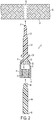
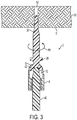
- FIGs. 1 - 4 Installation of the swivel hanger system to secure the anchor and swivel members to a support member is now described with reference to FIGs. 1 - 4 .
- Attachment of the swivel member 4 with the anchor member 20 to facilitate swivel movements of the swivel member about the anchor head 22 has been described herein.
- the tool 40 can be inserted at its second end 42 into a screw driver handle or other tool driving device (for example, in the bit holder of an electronic power drill). Referring to FIGs.
- the tool 40 is inserted into the swivel member 4, via the opening at the swivel member upper or second end 6, when the swivel member 4 is aligned generally in the same or similar lengthwise direction as the anchor member 20.
- the lower or first end 44 of the tool is engaged with the receptacle or indentation 23 at the anchor head 22.
- the lower or first end 24 of the anchor member 20 abuts against a surface 51 of the support member 50, where the support member can be, for example, a side wall or top/ceiling wall of a room or other structure such as a steel beam.
- the tool 40 is rotated while force is applied to the anchor member 20 via the tool 40.
- the swivel member 4 is free to rotate or swivel in various directions in relation to the anchor member 20 and support member 50 when the anchor member is secured with the support member, and this is possible regardless of how the support member is aligned in relation to a ground surface (for example, regardless of whether the support surface is a ceiling wall that is generally parallel with a ground surface as shown in FIG. 4 , or a sidewall as shown in FIGs.
- FIG. 5 shows how the swivel member 4 can achieve swivel movements in relation to the anchor member 20 are shown in FIG. 5 (see rotational arrow R2 ) and FIG. 6 (see rotational arrow R3 ).
- This configuration provides a distance D1 (defined as the distance between the flat upper surface of the anchor head 22 including the indentation 23 and the support surface 51 ) that is sufficiently greater than a maximum distance D2 (defined as the distance between the rounded first end 8 of the swivel member 4 and the support surface 51 when the swivel member 4 is generally aligned in the same lengthwise direction as the anchor member 20 ) .
- this provides a maximum insertion distance at which the anchor member 20 can be inserted into the support member 50 and also ensures a sufficient spacing (distance D2 ) is maintained that prevents pinching or restricted swivel movement of the swivel member 4 by either or both the anchor member 20 and the support surface 51.
- the flange end 26 of the anchor member 20 provides a stop to prevent further insertion of the anchor member 20 into the support member bore 52 during installation, thus ensuring the sufficient spacing (distance D2 ) is always maintained.
- An object can be supported by the swing hanger system 2 by connecting the object to the swivel member 4, such that the object is suspended in the same general orientation from the support member 50 as the swivel member 4.
- an object (such as a potted plant, a decorative art structure, a shelving structure, or any other selected device or component) can include a threaded connector that secures (via threaded engagement) within the threaded interior surface 10 of the swivel member 4 to facilitate a suspended connection between the object and the support surface 50 via the swivel hanger system 2.
- FIGs. 7 - 12 A swivel hanger system 102 in accordance with the present invention is depicted in FIGs. 7 - 12 .
- the tool 140, swivel member 104 and anchor member 120 are similar to those components described for the system 2 of FIGs. 1 - 6 , with the exception that the anchor member 120 does not include a flange (which serves as a stop for insertion of the anchor member into the bore of a support member) at an end of the threaded main body portion 128. Instead, a flange 146 is provided on the tool 140, and (as described herein) this flange provides a stop to prevent insertion of the anchor member 120 beyond a certain distance within the support member 50.
- swivel member 104 of system 102 has a substantially similar configuration as swivel member 4 of system 2, including a flat, upper or second end 106 with an opening to a hollow interior and a rounded, lower or first end 108 also having an opening to the hollow interior and a slot or cut-out section 112 at the first end 108.
- Anchor member 120 of system 102 also has a similar configuration as anchor member 20 of system 2, including a threaded main body portion 128 that extends between a pillar member 125 and a pointed first end 124.
- the anchor member 120 differs from anchor member 20 of system 2 in that anchor member 120 does not include any flange end for the main body portion 128.
- the upper or second end of the main body portion 128 extends to the pillar 125, where the pillar 125 connects the upper/second end of the main body portion 128 and the anchor head 122.
- the anchor head 122 is substantially similar to the anchor head 22 of system 2, including a flat upper side with a patterned depression or indentation 123 (for example, in the shape of a six pointed star) and a hemispherical shaped underside that corresponds with the rounded first end 108 of the swivel member 104 (so as to form a ball-and-socket type joint when these components are coupled together as shown in the figures).
- the tool 140 of system 102 is similar to tool 40 of system 2, including a lower or first end 144, an upper or second end 142, and a main body portion 145 having a multi-faceted exterior periphery, where the first end 144 has a reduced cross-sectional dimension in relation to the tool main body portion 145 and further has a cross-sectional geometric shape that corresponds with the indentation 123 of the anchor head 122 (e.g., a six pointed star-shaped configuration).
- Tool 140 further includes a flange 146 that extends transversely from the main body portion 145 at a selected location from each of the ends 142, 144.
- the size of the flange 146 is dimensioned such that its diameter or greatest width is larger than the opening at the upper or second end 106 of the swivel member 104.
- the first end 144 of the tool 140 can sufficiently engage with the indentation 123 of the anchor head 122 within the swivel member 104 during installation (in which a portion of the anchor member 120 is inserted within the bore 52 of the support surface 50).
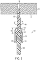
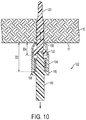
- FIGs. 7 - 10 Installation of the system 102 is now described with reference to FIGs. 7 - 10 .
- the coupling of the swivel member 104 and the anchor member 120 is achieved in a substantially similar manner as that previously described for system 2.
- the swivel member 104 and anchor member 120 are aligned such that the lower or first end 144 of tool 140 can be inserted into the opening at the upper or second end 106 of the swivel member 104 so as to engage with the indentation 123 of anchor head 122.
- FIG. 7 - 9 the swivel member 104 and anchor member 120 are aligned such that the lower or first end 144 of tool 140 can be inserted into the opening at the upper or second end 106 of the swivel member 104 so as to engage with the indentation 123 of anchor head 122.
- a spacing or gap distance D4 is defined between the flat upper side of the anchor head 122 and the lower or first end 108 of the swivel member 104 (when the anchor member 120 and swivel member 104 are generally aligned in the same lengthwise direction).
- This gap distance D4 allows for engagement of the tool first end 144 with the anchor head indentation 123 to facilitate transfer of linear and/or rotational forces from the tool 140 to the anchor member 120 (so as to insert the anchor member into the support surface bore 52).
- Anchor insertion is initiated by abutting the lower or first end 124 of the anchor member 120 against the surface 51 of the support member 50 (for example, a side wall or top/ceiling wall of a room).
- the tool 140 is rotated while force is applied to the anchor member 20 via the tool 40 (due to engagement of the tool first end 144 with the anchor head indentation 123). This causes rotation of the anchor member 120 (for example, in rotational direction R4 ) and movement of the anchor member into the bore 52.
- the anchor member 120 has been inserted into the support surface bore 52 (via action of the tool 140 ) to the point where first end 108 abuts support surface 51.
- the tool 140 cannot move any further toward surface 51 due to the intervening swivel member 104.
- rotation of tool 140 still advances anchor member 120 further into surface 51. This advancement via tool 140 rotation will continue until anchor member 120 moves forward (into support surface 50 ) enough that first end 144 is no longer engaged in head indentation 123 and can therefore no longer transfer rotational force to anchor member 120.
- the anchor member 120 has been inserted within the support surface bore 52 (via action of the tool 140 ) to the furthest permissible extent (i.e., a maximum insertion distance of the anchor member has been reached) based upon the system configuration.
- the anchor member 120 is prevented from further movement into the bore 152 when the lower or first end 108 of the swivel member 104 engages the support surface 51.
- the present systems limits the amount anchor member 120 can be driven into a support surface to ensure that there is sufficient gap between anchor head 122 and the support surface so that end 108 of swivel member has sufficient space to swivel without obstruction.
- the present system allows for this over tightening prevention system to be achieved without a stop structure such as flange end 26 on anchor member 20.
- the swivel member 104 can rotate at a variety of different orientations in relation to the anchor member 120 and support surface 51 (as indicated by rotation arrows R5 and R6 in FIGs. 11 and 12 ).
- An object can be supported by the swivel system 102 via connection between a threaded connector of the object and the threaded interior surface 110 at the upper or second end 106 of the swivel member 104.
- the swivel hanger system of the present invention facilitates an easy connection to a support member with a built-in stop mechanism that prevents securing of the anchor member too far within the support member. This in turn ensures free swivel movements (i.e., horizontal and/or vertical rotational movements) of the swivel member in relation to the anchor member and support member after installation.
Landscapes
- Engineering & Computer Science (AREA)
- General Engineering & Computer Science (AREA)
- Mechanical Engineering (AREA)
- Supports Or Holders For Household Use (AREA)
- Joining Of Building Structures In Genera (AREA)
- Dowels (AREA)
Claims (6)
- Drehaufhängersystem (102), umfassend:ein Dübelelement (120), umfassend ein erstes Ende und ein zweites Ende, einen Dübelkopf, der an dem zweiten Ende des Dübelelements angeordnet ist, und einen verlängerten Körper, der zwischen den ersten und zweiten Enden des Dübelelements angeordnet ist, wobei das erste Ende und mindestens ein Abschnitt des verlängerten Körpers konfiguriert sind, um in ein Stützelement eingesetzt zu werden, wenn das System mit dem Stützelement verbunden wird,ein Drehelement (104), das ein erstes Ende und ein zweites Ende aufweist, wobei jedes der ersten und zweiten Enden des Drehelements eine Öffnung beinhaltet, die sich in einen hohlen Innenraum des Drehelements erstreckt, und das erste Ende davon eine Steckbuchse beinhaltet, die konfiguriert ist, um sich drehend an den Dübelkopf zu koppeln, sodass sich der Dübelkopf innerhalb des hohlen Innenraums befindet und sich der verlängerte Körper durch die Öffnung an dem ersten Ende des Drehelements hindurch erstreckt, undein Werkzeug (140), das konfiguriert ist, um das Dübelelement in das Stützelement einzusetzen, wobei das Werkzeug konfiguriert ist, um sich in den hohlen Innenraum des Drehelements über die Öffnung des zweiten Endes des Drehelements zu erstrecken, um in ein Ende des Werkzeugs mit dem Dübelkopf einzugreifen, dadurch gekennzeichnet, dass das Werkzeug einen Flansch (146) aufweist, der sich zwischen einem ersten Ende und einem zweiten Ende des Werkzeugs befindet, und wobei ein erster Teil einer zweiteiligen Arretierstruktur das zweite Ende (106) des Drehelements umfasst und ein zweiter Teil der zweiteiligen Arretierstruktur den an dem Werkzeug bereitgestellten Flansch umfasst, wobei die ersten und zweiten Teile der zweiteiligen Arretierstruktur konfiguriert sind, um ineinander einzugreifen, wenn ein Abschnitt des Werkzeugs, welcher das erste Ende des Werkzeugs beinhaltet, innerhalb des hohlen Innenraums des Drehelements eingesetzt wird, um einen Einsatzabstand zu begrenzen, bis zu welchem das Dübelelement in das Stützelement eingesetzt werden kann.
- Drehaufhängersystem nach Anspruch 1, wobei der Dübelkopf eine Oberfläche (123) beinhaltet, die eine gemusterte Einkerbung aufweist und das Werkzeugende eine gemusterte Außenfläche beinhaltet, die der gemusterten Einkerbung entspricht.
- Drehaufhängersystem nach Anspruch 1, wobei der Dübelkopf eine Eingriffstruktur (123) aufweist, die in das Werkzeug (140) eingreift, um eine Rotation des Dübelelements über einen Gewindeschraubeneingriff in das Stützelement ermöglicht.
- Drehaufhängersystem nach Anspruch 1, wobei das erste Ende (108) des Drehelements abgerundet ist und das Drehelement einen Ausschnitt (112) beinhaltet, der sich bis zu der Öffnung an dem abgerundeten ersten Ende erstreckt und der Dübelkopf passend dimensioniert ist, um in den hohlen Innenraum des Drehelements über den Ausschnitt und die abgerundete Öffnung des ersten Endes eingesetzt zu werden.
- Drehaufhängersystem nach Anspruch 1, wobei der hohle Innenraum des Drehelements eine Gewinde-Innenfläche (110) beinhaltet, die sich benachbart der Öffnung des zweiten Endes des Drehelements (104) derart erstreckt, um eine Befestigung eines Objekts an dem Drehelement während der Verwendung des Systems zu ermöglichen.
- Drehaufhängersystem nach Anspruch 1, wobei das erste Ende (108) des Drehelements abgerundet ist und der Dübelkopf eine halbkugelförmige Gestalt aufweist, die dem abgerundeten ersten Ende des Drehelements (104) entspricht, sodass ein Koppeln des abgerundeten ersten Endes Drehbewegungen des Drehelements in Bezug auf den Dübelkopf ermöglicht.
Applications Claiming Priority (2)
| Application Number | Priority Date | Filing Date | Title |
|---|---|---|---|
| US14/561,590 US20160160906A1 (en) | 2014-12-05 | 2014-12-05 | Swivel hanger |
| PCT/US2015/062976 WO2016089761A1 (en) | 2014-12-05 | 2015-11-30 | Swivel hanger |
Publications (3)
| Publication Number | Publication Date |
|---|---|
| EP3227569A1 EP3227569A1 (de) | 2017-10-11 |
| EP3227569A4 EP3227569A4 (de) | 2018-07-11 |
| EP3227569B1 true EP3227569B1 (de) | 2021-03-24 |
Family
ID=56092290
Family Applications (1)
| Application Number | Title | Priority Date | Filing Date |
|---|---|---|---|
| EP15865313.9A Active EP3227569B1 (de) | 2014-12-05 | 2015-11-30 | Schwenkbarer aufhänger |
Country Status (5)
| Country | Link |
|---|---|
| US (3) | US20160160906A1 (de) |
| EP (1) | EP3227569B1 (de) |
| CN (1) | CN107002734B (de) |
| TW (1) | TWI686559B (de) |
| WO (1) | WO2016089761A1 (de) |
Families Citing this family (8)
| Publication number | Priority date | Publication date | Assignee | Title |
|---|---|---|---|---|
| US20160160906A1 (en) * | 2014-12-05 | 2016-06-09 | Black & Decker Inc. | Swivel hanger |
| AU2017210491B2 (en) * | 2016-08-04 | 2022-10-13 | Black & Decker Inc. | Swivel hanger system |
| TWM567818U (zh) * | 2018-07-03 | 2018-10-01 | 宇加工業股份有限公司 | 壁釘 |
| US10619344B1 (en) * | 2019-04-12 | 2020-04-14 | Kaoru Taneichi | Reinforcing hardware for wooden housing |
| US12168989B2 (en) * | 2020-05-28 | 2024-12-17 | Illinois Tool Works Inc. | Self-drilling expandable anchor and methods of use and installation thereof |
| AU2021342148B2 (en) * | 2020-09-11 | 2024-11-14 | Kyocera Senco Industrial Tools, Inc. | Fastener driver tool with rafter hanger |
| US12258989B2 (en) * | 2020-11-13 | 2025-03-25 | Guangzhou Metro Design & Research Institute Co., Ltd. | Connection lock for prefabricated components |
| US12305678B2 (en) | 2022-04-05 | 2025-05-20 | Illinois Tool Works Inc. | Expandable anchor installation tool and methods of use thereof |
Family Cites Families (46)
| Publication number | Priority date | Publication date | Assignee | Title |
|---|---|---|---|---|
| US1032347A (en) | 1911-07-15 | 1912-07-09 | Union Typewriter Co | Type-writing and computing machine. |
| GB393090A (en) * | 1932-06-14 | 1933-06-01 | Amal Ltd | Swivel linkage joints |
| US2765134A (en) * | 1953-10-09 | 1956-10-02 | Arthur R Hill | Anchor bolt structure with supporting member |
| US3002466A (en) * | 1958-03-25 | 1961-10-03 | Guiberson Corp | Swab cup support |
| US3435729A (en) * | 1967-01-20 | 1969-04-01 | Burr Ban Tool Service Co | Hole grooving device |
| JPS5544936B2 (de) | 1973-03-20 | 1980-11-14 | ||
| DE3923996A1 (de) * | 1989-07-20 | 1991-01-31 | Lutz Biedermann | Aufnahmeteil zum gelenkigen verbinden mit einer schraube zum bilden einer pedikelschraube |
| US5101698A (en) * | 1990-05-24 | 1992-04-07 | Bernardo Paradiso | Screw head depth limiter |
| DE4214343A1 (de) * | 1992-05-05 | 1993-11-11 | Fischer Artur Werke Gmbh | Vorrichtung zur Herstellung von Bohrlöchern mit Hinterschneidung |
| US6176861B1 (en) * | 1994-10-25 | 2001-01-23 | Sdgi Holdings, Inc. | Modular spinal system |
| US5624198A (en) * | 1996-02-06 | 1997-04-29 | Zumtobel Staff Lighting, Inc. | Swivel connector |
| US6019555A (en) * | 1997-11-20 | 2000-02-01 | Hudson Products Corporation | Debur tool for simultaneously removing burrs from and chamfering a hole in a workpiece |
| US6280442B1 (en) * | 1999-09-01 | 2001-08-28 | Sdgi Holdings, Inc. | Multi-axial bone screw assembly |
| DE20005059U1 (de) | 2000-03-20 | 2000-05-25 | Feigl, Bernhard, Lochau | Befestigungsvorrichtung |
| US6443680B1 (en) * | 2001-05-04 | 2002-09-03 | Illinois Tool Works Inc. | Mounting apparatus having a swivel head |
| US6520963B1 (en) * | 2001-08-13 | 2003-02-18 | Mckinley Lawrence M. | Vertebral alignment and fixation assembly |
| US6722826B2 (en) * | 2001-09-11 | 2004-04-20 | Brian M. Cavanaugh | Internal cavity cutting tool with stable support |
| US6935821B2 (en) | 2002-04-05 | 2005-08-30 | Illinois Tool Works, Inc. | Mushrooming expandable anchor |
| US6868757B2 (en) * | 2003-05-20 | 2005-03-22 | Huck International, Inc. | Blind fastener and nose assembly for installation of the blind fastener |
| US6848346B1 (en) * | 2003-07-09 | 2005-02-01 | Illinois Tool Work Inc | Hurricane shutter fastener installation bit |
| GB2426804B (en) * | 2004-02-26 | 2007-02-28 | Stefan Joseph Szoke | A fastener |
| DE102004010380A1 (de) * | 2004-03-03 | 2005-09-22 | Biedermann Motech Gmbh | Verankerungselement und Stabilisierungseinrichtung zur dynamischen Stabilisierung von Wirbeln bzw. Knochen mit einem solchen Verankerungselement |
| US7722654B2 (en) * | 2004-10-05 | 2010-05-25 | Warsaw Orthopedic, Inc. | Spinal implants with multi-axial anchor assembly and methods |
| US8221472B2 (en) * | 2005-04-25 | 2012-07-17 | Synthes Usa, Llc | Bone anchor with locking cap and method of spinal fixation |
| US7188554B2 (en) | 2005-06-09 | 2007-03-13 | Atlas Spine, Inc. | Medical fastener and tool |
| US7607854B1 (en) * | 2005-06-15 | 2009-10-27 | 3Form, Inc. | Variable angle standoff |
| US8002806B2 (en) * | 2005-10-20 | 2011-08-23 | Warsaw Orthopedic, Inc. | Bottom loading multi-axial screw assembly |
| US8100946B2 (en) * | 2005-11-21 | 2012-01-24 | Synthes Usa, Llc | Polyaxial bone anchors with increased angulation |
| US7857563B2 (en) * | 2006-02-28 | 2010-12-28 | Monogram Aerospace Fasteners, Inc. | Mechanically locked blind bolt fastener |
| US7780134B2 (en) * | 2006-06-14 | 2010-08-24 | Illinois Tool Works Inc. | Anchor assembly with large range of motion suspension members, and restraint systems for suspended components |
| US20080008553A1 (en) * | 2006-07-10 | 2008-01-10 | Robert Andrew Gillis | Self-drilling anchor screw and method of using the same |
| ITMI20061401A1 (it) * | 2006-07-19 | 2008-01-20 | Ruotemilano S R L | Dispositivo per fissare un raggio al cerchione di una ruota a raggi |
| US7637686B2 (en) * | 2007-03-02 | 2009-12-29 | The Boeing Company | Swivel fitting attachment apparatus |
| US7467477B1 (en) * | 2007-07-26 | 2008-12-23 | Shimano Inc. | Rear derailleur hanger alignment tool |
| US8636778B2 (en) * | 2009-02-11 | 2014-01-28 | Pioneer Surgical Technology, Inc. | Wide angulation coupling members for bone fixation system |
| US9358050B2 (en) * | 2011-10-14 | 2016-06-07 | Globus Medical, Inc. | Orthopedic anchor assembly |
| DE102009050139A1 (de) * | 2009-10-20 | 2011-04-21 | Carl Stahl Gmbh | Anschlagmittel sowie Lasthebesystem für die Benutzung mit einem solchen Anschlagmittel |
| CN102562755A (zh) | 2010-12-28 | 2012-07-11 | 鸿富锦精密工业(深圳)有限公司 | 紧固件、与其配合的驱动件及成型该紧固件的冲子 |
| US8337530B2 (en) | 2011-03-09 | 2012-12-25 | Zimmer Spine, Inc. | Polyaxial pedicle screw with increased angulation |
| CA2842324C (en) | 2011-07-20 | 2020-02-25 | Michael H. Horwitz | Minimal incision removable bone screw, driver, and method of use |
| US9198769B2 (en) * | 2011-12-23 | 2015-12-01 | Pioneer Surgical Technology, Inc. | Bone anchor assembly, bone plate system, and method |
| US20140277159A1 (en) * | 2013-03-14 | 2014-09-18 | DePuy Synthes Products, LLC | Bottom-loading bone anchor assemblies |
| US9367317B2 (en) * | 2013-07-03 | 2016-06-14 | Intel Corporation | Loop streaming detector for standard and complex instruction types |
| US9433451B2 (en) | 2013-12-09 | 2016-09-06 | Acumed Llc | Hip fixation system with a compliant fixation element |
| US20160160906A1 (en) * | 2014-12-05 | 2016-06-09 | Black & Decker Inc. | Swivel hanger |
| US10132347B2 (en) * | 2014-12-05 | 2018-11-20 | Black & Decker Inc. | Swivel hanger system |
-
2014
- 2014-12-05 US US14/561,590 patent/US20160160906A1/en not_active Abandoned
-
2015
- 2015-11-30 CN CN201580066062.5A patent/CN107002734B/zh active Active
- 2015-11-30 WO PCT/US2015/062976 patent/WO2016089761A1/en not_active Ceased
- 2015-11-30 EP EP15865313.9A patent/EP3227569B1/de active Active
- 2015-12-04 TW TW104140821A patent/TWI686559B/zh not_active IP Right Cessation
-
2018
- 2018-06-06 US US16/001,567 patent/US10816031B2/en active Active
-
2020
- 2020-10-12 US US17/067,940 patent/US12504039B2/en active Active
Non-Patent Citations (1)
| Title |
|---|
| None * |
Also Published As
| Publication number | Publication date |
|---|---|
| TW201632740A (zh) | 2016-09-16 |
| EP3227569A4 (de) | 2018-07-11 |
| US20210025442A1 (en) | 2021-01-28 |
| US20160160906A1 (en) | 2016-06-09 |
| TWI686559B (zh) | 2020-03-01 |
| US20180283443A1 (en) | 2018-10-04 |
| US12504039B2 (en) | 2025-12-23 |
| WO2016089761A1 (en) | 2016-06-09 |
| CN107002734A (zh) | 2017-08-01 |
| EP3227569A1 (de) | 2017-10-11 |
| CN107002734B (zh) | 2022-12-30 |
| US10816031B2 (en) | 2020-10-27 |
Similar Documents
| Publication | Publication Date | Title |
|---|---|---|
| US12504039B2 (en) | Swivel hanger | |
| US20180258977A1 (en) | Fastener with Loop or Hook | |
| US8448910B2 (en) | Wall mountable holder system | |
| US8333356B2 (en) | Wall mountable holder system | |
| US8844886B2 (en) | Wall hanger | |
| US10132347B2 (en) | Swivel hanger system | |
| US9364903B2 (en) | Drilling apparatus and method | |
| US9511482B2 (en) | Drive bit | |
| US9221155B1 (en) | Lag driver | |
| US20130269169A1 (en) | Hinged arm mechanically activated fastener | |
| US9850938B2 (en) | Fastener with loop or hook | |
| US20050132848A1 (en) | Eye screw and eye screw socket | |
| US6854364B1 (en) | Screw hook socket | |
| EP3279484B1 (de) | Schwenkbares aufhängungssystem | |
| TWM369830U (en) | Tool extender bar with universal joint | |
| US20220412392A1 (en) | Multifunctional fastener | |
| CA3057952A1 (en) | A fixing, kit, and method | |
| US20240391062A1 (en) | Multi-function socket tool | |
| US20050155156A1 (en) | Screw hook tool | |
| EP4592536A2 (de) | Gewindestangenbügel | |
| EP2941573B1 (de) | Länglicher stecker mit einem stiftartigen körper mit einer länglichen bohrung zur aufnahme eines nagels, einer schraube oder dergleichen | |
| JP2019100067A (ja) | 木造住宅用補強金物 |
Legal Events
| Date | Code | Title | Description |
|---|---|---|---|
| STAA | Information on the status of an ep patent application or granted ep patent |
Free format text: STATUS: THE INTERNATIONAL PUBLICATION HAS BEEN MADE |
|
| PUAI | Public reference made under article 153(3) epc to a published international application that has entered the european phase |
Free format text: ORIGINAL CODE: 0009012 |
|
| STAA | Information on the status of an ep patent application or granted ep patent |
Free format text: STATUS: REQUEST FOR EXAMINATION WAS MADE |
|
| 17P | Request for examination filed |
Effective date: 20170615 |
|
| AK | Designated contracting states |
Kind code of ref document: A1 Designated state(s): AL AT BE BG CH CY CZ DE DK EE ES FI FR GB GR HR HU IE IS IT LI LT LU LV MC MK MT NL NO PL PT RO RS SE SI SK SM TR |
|
| AX | Request for extension of the european patent |
Extension state: BA ME |
|
| RIN1 | Information on inventor provided before grant (corrected) |
Inventor name: BAUER, ADAM P. Inventor name: BLAESS, DONALD K. Inventor name: THEISMANN, MARK |
|
| DAV | Request for validation of the european patent (deleted) | ||
| DAX | Request for extension of the european patent (deleted) | ||
| A4 | Supplementary search report drawn up and despatched |
Effective date: 20180613 |
|
| RIC1 | Information provided on ipc code assigned before grant |
Ipc: F16B 13/04 20060101AFI20180607BHEP |
|
| STAA | Information on the status of an ep patent application or granted ep patent |
Free format text: STATUS: EXAMINATION IS IN PROGRESS |
|
| 17Q | First examination report despatched |
Effective date: 20190704 |
|
| RIC1 | Information provided on ipc code assigned before grant |
Ipc: F16B 25/10 20060101ALI20200827BHEP Ipc: F16B 45/00 20060101ALI20200827BHEP Ipc: F16B 35/06 20060101ALI20200827BHEP Ipc: F16B 25/00 20060101ALI20200827BHEP Ipc: F16B 13/04 20060101AFI20200827BHEP Ipc: F16C 11/06 20060101ALI20200827BHEP |
|
| GRAP | Despatch of communication of intention to grant a patent |
Free format text: ORIGINAL CODE: EPIDOSNIGR1 |
|
| STAA | Information on the status of an ep patent application or granted ep patent |
Free format text: STATUS: GRANT OF PATENT IS INTENDED |
|
| INTG | Intention to grant announced |
Effective date: 20201013 |
|
| GRAJ | Information related to disapproval of communication of intention to grant by the applicant or resumption of examination proceedings by the epo deleted |
Free format text: ORIGINAL CODE: EPIDOSDIGR1 |
|
| STAA | Information on the status of an ep patent application or granted ep patent |
Free format text: STATUS: EXAMINATION IS IN PROGRESS |
|
| GRAP | Despatch of communication of intention to grant a patent |
Free format text: ORIGINAL CODE: EPIDOSNIGR1 |
|
| STAA | Information on the status of an ep patent application or granted ep patent |
Free format text: STATUS: GRANT OF PATENT IS INTENDED |
|
| INTC | Intention to grant announced (deleted) | ||
| INTG | Intention to grant announced |
Effective date: 20201216 |
|
| GRAS | Grant fee paid |
Free format text: ORIGINAL CODE: EPIDOSNIGR3 |
|
| GRAA | (expected) grant |
Free format text: ORIGINAL CODE: 0009210 |
|
| STAA | Information on the status of an ep patent application or granted ep patent |
Free format text: STATUS: THE PATENT HAS BEEN GRANTED |
|
| AK | Designated contracting states |
Kind code of ref document: B1 Designated state(s): AL AT BE BG CH CY CZ DE DK EE ES FI FR GB GR HR HU IE IS IT LI LT LU LV MC MK MT NL NO PL PT RO RS SE SI SK SM TR |
|
| REG | Reference to a national code |
Ref country code: GB Ref legal event code: FG4D |
|
| REG | Reference to a national code |
Ref country code: CH Ref legal event code: EP |
|
| REG | Reference to a national code |
Ref country code: IE Ref legal event code: FG4D |
|
| REG | Reference to a national code |
Ref country code: AT Ref legal event code: REF Ref document number: 1374763 Country of ref document: AT Kind code of ref document: T Effective date: 20210415 Ref country code: DE Ref legal event code: R096 Ref document number: 602015067318 Country of ref document: DE |
|
| REG | Reference to a national code |
Ref country code: LT Ref legal event code: MG9D |
|
| PG25 | Lapsed in a contracting state [announced via postgrant information from national office to epo] |
Ref country code: GR Free format text: LAPSE BECAUSE OF FAILURE TO SUBMIT A TRANSLATION OF THE DESCRIPTION OR TO PAY THE FEE WITHIN THE PRESCRIBED TIME-LIMIT Effective date: 20210625 Ref country code: FI Free format text: LAPSE BECAUSE OF FAILURE TO SUBMIT A TRANSLATION OF THE DESCRIPTION OR TO PAY THE FEE WITHIN THE PRESCRIBED TIME-LIMIT Effective date: 20210324 Ref country code: HR Free format text: LAPSE BECAUSE OF FAILURE TO SUBMIT A TRANSLATION OF THE DESCRIPTION OR TO PAY THE FEE WITHIN THE PRESCRIBED TIME-LIMIT Effective date: 20210324 Ref country code: BG Free format text: LAPSE BECAUSE OF FAILURE TO SUBMIT A TRANSLATION OF THE DESCRIPTION OR TO PAY THE FEE WITHIN THE PRESCRIBED TIME-LIMIT Effective date: 20210624 Ref country code: NO Free format text: LAPSE BECAUSE OF FAILURE TO SUBMIT A TRANSLATION OF THE DESCRIPTION OR TO PAY THE FEE WITHIN THE PRESCRIBED TIME-LIMIT Effective date: 20210624 |
|
| PG25 | Lapsed in a contracting state [announced via postgrant information from national office to epo] |
Ref country code: SE Free format text: LAPSE BECAUSE OF FAILURE TO SUBMIT A TRANSLATION OF THE DESCRIPTION OR TO PAY THE FEE WITHIN THE PRESCRIBED TIME-LIMIT Effective date: 20210324 Ref country code: RS Free format text: LAPSE BECAUSE OF FAILURE TO SUBMIT A TRANSLATION OF THE DESCRIPTION OR TO PAY THE FEE WITHIN THE PRESCRIBED TIME-LIMIT Effective date: 20210324 Ref country code: LV Free format text: LAPSE BECAUSE OF FAILURE TO SUBMIT A TRANSLATION OF THE DESCRIPTION OR TO PAY THE FEE WITHIN THE PRESCRIBED TIME-LIMIT Effective date: 20210324 |
|
| REG | Reference to a national code |
Ref country code: NL Ref legal event code: MP Effective date: 20210324 |
|
| REG | Reference to a national code |
Ref country code: AT Ref legal event code: MK05 Ref document number: 1374763 Country of ref document: AT Kind code of ref document: T Effective date: 20210324 |
|
| PG25 | Lapsed in a contracting state [announced via postgrant information from national office to epo] |
Ref country code: NL Free format text: LAPSE BECAUSE OF FAILURE TO SUBMIT A TRANSLATION OF THE DESCRIPTION OR TO PAY THE FEE WITHIN THE PRESCRIBED TIME-LIMIT Effective date: 20210324 |
|
| PG25 | Lapsed in a contracting state [announced via postgrant information from national office to epo] |
Ref country code: CZ Free format text: LAPSE BECAUSE OF FAILURE TO SUBMIT A TRANSLATION OF THE DESCRIPTION OR TO PAY THE FEE WITHIN THE PRESCRIBED TIME-LIMIT Effective date: 20210324 Ref country code: EE Free format text: LAPSE BECAUSE OF FAILURE TO SUBMIT A TRANSLATION OF THE DESCRIPTION OR TO PAY THE FEE WITHIN THE PRESCRIBED TIME-LIMIT Effective date: 20210324 Ref country code: LT Free format text: LAPSE BECAUSE OF FAILURE TO SUBMIT A TRANSLATION OF THE DESCRIPTION OR TO PAY THE FEE WITHIN THE PRESCRIBED TIME-LIMIT Effective date: 20210324 Ref country code: SM Free format text: LAPSE BECAUSE OF FAILURE TO SUBMIT A TRANSLATION OF THE DESCRIPTION OR TO PAY THE FEE WITHIN THE PRESCRIBED TIME-LIMIT Effective date: 20210324 Ref country code: AT Free format text: LAPSE BECAUSE OF FAILURE TO SUBMIT A TRANSLATION OF THE DESCRIPTION OR TO PAY THE FEE WITHIN THE PRESCRIBED TIME-LIMIT Effective date: 20210324 |
|
| PG25 | Lapsed in a contracting state [announced via postgrant information from national office to epo] |
Ref country code: RO Free format text: LAPSE BECAUSE OF FAILURE TO SUBMIT A TRANSLATION OF THE DESCRIPTION OR TO PAY THE FEE WITHIN THE PRESCRIBED TIME-LIMIT Effective date: 20210324 Ref country code: SK Free format text: LAPSE BECAUSE OF FAILURE TO SUBMIT A TRANSLATION OF THE DESCRIPTION OR TO PAY THE FEE WITHIN THE PRESCRIBED TIME-LIMIT Effective date: 20210324 Ref country code: PT Free format text: LAPSE BECAUSE OF FAILURE TO SUBMIT A TRANSLATION OF THE DESCRIPTION OR TO PAY THE FEE WITHIN THE PRESCRIBED TIME-LIMIT Effective date: 20210726 Ref country code: PL Free format text: LAPSE BECAUSE OF FAILURE TO SUBMIT A TRANSLATION OF THE DESCRIPTION OR TO PAY THE FEE WITHIN THE PRESCRIBED TIME-LIMIT Effective date: 20210324 Ref country code: IS Free format text: LAPSE BECAUSE OF FAILURE TO SUBMIT A TRANSLATION OF THE DESCRIPTION OR TO PAY THE FEE WITHIN THE PRESCRIBED TIME-LIMIT Effective date: 20210724 |
|
| REG | Reference to a national code |
Ref country code: DE Ref legal event code: R097 Ref document number: 602015067318 Country of ref document: DE |
|
| PG25 | Lapsed in a contracting state [announced via postgrant information from national office to epo] |
Ref country code: AL Free format text: LAPSE BECAUSE OF FAILURE TO SUBMIT A TRANSLATION OF THE DESCRIPTION OR TO PAY THE FEE WITHIN THE PRESCRIBED TIME-LIMIT Effective date: 20210324 Ref country code: ES Free format text: LAPSE BECAUSE OF FAILURE TO SUBMIT A TRANSLATION OF THE DESCRIPTION OR TO PAY THE FEE WITHIN THE PRESCRIBED TIME-LIMIT Effective date: 20210324 Ref country code: DK Free format text: LAPSE BECAUSE OF FAILURE TO SUBMIT A TRANSLATION OF THE DESCRIPTION OR TO PAY THE FEE WITHIN THE PRESCRIBED TIME-LIMIT Effective date: 20210324 |
|
| PLBE | No opposition filed within time limit |
Free format text: ORIGINAL CODE: 0009261 |
|
| STAA | Information on the status of an ep patent application or granted ep patent |
Free format text: STATUS: NO OPPOSITION FILED WITHIN TIME LIMIT |
|
| PG25 | Lapsed in a contracting state [announced via postgrant information from national office to epo] |
Ref country code: SI Free format text: LAPSE BECAUSE OF FAILURE TO SUBMIT A TRANSLATION OF THE DESCRIPTION OR TO PAY THE FEE WITHIN THE PRESCRIBED TIME-LIMIT Effective date: 20210324 |
|
| 26N | No opposition filed |
Effective date: 20220104 |
|
| PG25 | Lapsed in a contracting state [announced via postgrant information from national office to epo] |
Ref country code: IS Free format text: LAPSE BECAUSE OF FAILURE TO SUBMIT A TRANSLATION OF THE DESCRIPTION OR TO PAY THE FEE WITHIN THE PRESCRIBED TIME-LIMIT Effective date: 20210724 |
|
| PG25 | Lapsed in a contracting state [announced via postgrant information from national office to epo] |
Ref country code: MC Free format text: LAPSE BECAUSE OF FAILURE TO SUBMIT A TRANSLATION OF THE DESCRIPTION OR TO PAY THE FEE WITHIN THE PRESCRIBED TIME-LIMIT Effective date: 20210324 |
|
| REG | Reference to a national code |
Ref country code: CH Ref legal event code: PL |
|
| PG25 | Lapsed in a contracting state [announced via postgrant information from national office to epo] |
Ref country code: BE Free format text: LAPSE BECAUSE OF NON-PAYMENT OF DUE FEES Effective date: 20211130 Ref country code: LU Free format text: LAPSE BECAUSE OF NON-PAYMENT OF DUE FEES Effective date: 20211130 |
|
| REG | Reference to a national code |
Ref country code: BE Ref legal event code: MM Effective date: 20211130 |
|
| PG25 | Lapsed in a contracting state [announced via postgrant information from national office to epo] |
Ref country code: IE Free format text: LAPSE BECAUSE OF NON-PAYMENT OF DUE FEES Effective date: 20211130 |
|
| PG25 | Lapsed in a contracting state [announced via postgrant information from national office to epo] |
Ref country code: FR Free format text: LAPSE BECAUSE OF NON-PAYMENT OF DUE FEES Effective date: 20211130 |
|
| PG25 | Lapsed in a contracting state [announced via postgrant information from national office to epo] |
Ref country code: IT Free format text: LAPSE BECAUSE OF FAILURE TO SUBMIT A TRANSLATION OF THE DESCRIPTION OR TO PAY THE FEE WITHIN THE PRESCRIBED TIME-LIMIT Effective date: 20210324 |
|
| PG25 | Lapsed in a contracting state [announced via postgrant information from national office to epo] |
Ref country code: HU Free format text: LAPSE BECAUSE OF FAILURE TO SUBMIT A TRANSLATION OF THE DESCRIPTION OR TO PAY THE FEE WITHIN THE PRESCRIBED TIME-LIMIT; INVALID AB INITIO Effective date: 20151130 |
|
| PG25 | Lapsed in a contracting state [announced via postgrant information from national office to epo] |
Ref country code: CY Free format text: LAPSE BECAUSE OF FAILURE TO SUBMIT A TRANSLATION OF THE DESCRIPTION OR TO PAY THE FEE WITHIN THE PRESCRIBED TIME-LIMIT Effective date: 20210324 |
|
| PG25 | Lapsed in a contracting state [announced via postgrant information from national office to epo] |
Ref country code: LI Free format text: LAPSE BECAUSE OF NON-PAYMENT OF DUE FEES Effective date: 20220701 Ref country code: CH Free format text: LAPSE BECAUSE OF NON-PAYMENT OF DUE FEES Effective date: 20220701 |
|
| PG25 | Lapsed in a contracting state [announced via postgrant information from national office to epo] |
Ref country code: MK Free format text: LAPSE BECAUSE OF FAILURE TO SUBMIT A TRANSLATION OF THE DESCRIPTION OR TO PAY THE FEE WITHIN THE PRESCRIBED TIME-LIMIT Effective date: 20210324 |
|
| PG25 | Lapsed in a contracting state [announced via postgrant information from national office to epo] |
Ref country code: MT Free format text: LAPSE BECAUSE OF FAILURE TO SUBMIT A TRANSLATION OF THE DESCRIPTION OR TO PAY THE FEE WITHIN THE PRESCRIBED TIME-LIMIT Effective date: 20210324 |
|
| PG25 | Lapsed in a contracting state [announced via postgrant information from national office to epo] |
Ref country code: TR Free format text: LAPSE BECAUSE OF FAILURE TO SUBMIT A TRANSLATION OF THE DESCRIPTION OR TO PAY THE FEE WITHIN THE PRESCRIBED TIME-LIMIT Effective date: 20210324 |
|
| PGFP | Annual fee paid to national office [announced via postgrant information from national office to epo] |
Ref country code: DE Payment date: 20251118 Year of fee payment: 11 |
|
| PGFP | Annual fee paid to national office [announced via postgrant information from national office to epo] |
Ref country code: GB Payment date: 20251120 Year of fee payment: 11 |