EP2941573B1 - Länglicher stecker mit einem stiftartigen körper mit einer länglichen bohrung zur aufnahme eines nagels, einer schraube oder dergleichen - Google Patents
Länglicher stecker mit einem stiftartigen körper mit einer länglichen bohrung zur aufnahme eines nagels, einer schraube oder dergleichen Download PDFInfo
- Publication number
- EP2941573B1 EP2941573B1 EP14739575.0A EP14739575A EP2941573B1 EP 2941573 B1 EP2941573 B1 EP 2941573B1 EP 14739575 A EP14739575 A EP 14739575A EP 2941573 B1 EP2941573 B1 EP 2941573B1
- Authority
- EP
- European Patent Office
- Prior art keywords
- lips
- elongate plug
- screw
- plug
- longitudinal bore
- Prior art date
- Legal status (The legal status is an assumption and is not a legal conclusion. Google has not performed a legal analysis and makes no representation as to the accuracy of the status listed.)
- Active
Links
Images




Classifications
-
- F—MECHANICAL ENGINEERING; LIGHTING; HEATING; WEAPONS; BLASTING
- F16—ENGINEERING ELEMENTS AND UNITS; GENERAL MEASURES FOR PRODUCING AND MAINTAINING EFFECTIVE FUNCTIONING OF MACHINES OR INSTALLATIONS; THERMAL INSULATION IN GENERAL
- F16B—DEVICES FOR FASTENING OR SECURING CONSTRUCTIONAL ELEMENTS OR MACHINE PARTS TOGETHER, e.g. NAILS, BOLTS, CIRCLIPS, CLAMPS, CLIPS OR WEDGES; JOINTS OR JOINTING
- F16B13/00—Dowels or other devices fastened in walls or the like by inserting them in holes made therein for that purpose
- F16B13/12—Separate metal or non-separate or non-metal dowel sleeves fastened by inserting the screw, nail or the like
- F16B13/124—Separate metal or non-separate or non-metal dowel sleeves fastened by inserting the screw, nail or the like fastened by inserting a threaded element, e.g. screw or bolt
-
- F—MECHANICAL ENGINEERING; LIGHTING; HEATING; WEAPONS; BLASTING
- F16—ENGINEERING ELEMENTS AND UNITS; GENERAL MEASURES FOR PRODUCING AND MAINTAINING EFFECTIVE FUNCTIONING OF MACHINES OR INSTALLATIONS; THERMAL INSULATION IN GENERAL
- F16B—DEVICES FOR FASTENING OR SECURING CONSTRUCTIONAL ELEMENTS OR MACHINE PARTS TOGETHER, e.g. NAILS, BOLTS, CIRCLIPS, CLAMPS, CLIPS OR WEDGES; JOINTS OR JOINTING
- F16B13/00—Dowels or other devices fastened in walls or the like by inserting them in holes made therein for that purpose
- F16B13/12—Separate metal or non-separate or non-metal dowel sleeves fastened by inserting the screw, nail or the like
- F16B13/126—Separate metal or non-separate or non-metal dowel sleeves fastened by inserting the screw, nail or the like fastened by inserting an unthreaded element, e.g. pin or nail
-
- F—MECHANICAL ENGINEERING; LIGHTING; HEATING; WEAPONS; BLASTING
- F16—ENGINEERING ELEMENTS AND UNITS; GENERAL MEASURES FOR PRODUCING AND MAINTAINING EFFECTIVE FUNCTIONING OF MACHINES OR INSTALLATIONS; THERMAL INSULATION IN GENERAL
- F16B—DEVICES FOR FASTENING OR SECURING CONSTRUCTIONAL ELEMENTS OR MACHINE PARTS TOGETHER, e.g. NAILS, BOLTS, CIRCLIPS, CLAMPS, CLIPS OR WEDGES; JOINTS OR JOINTING
- F16B13/00—Dowels or other devices fastened in walls or the like by inserting them in holes made therein for that purpose
- F16B13/12—Separate metal or non-separate or non-metal dowel sleeves fastened by inserting the screw, nail or the like
- F16B13/128—Separate metal or non-separate or non-metal dowel sleeves fastened by inserting the screw, nail or the like with extending protrusions, e.g. discs, segments, ridges, fingers or tongues
Definitions
- the invention relates to an elongate plug provided with a pin-like body with a longitudinal bore for receiving a nail, screw or the like therein.
- the plug according to the invention serves particularly for fastening to a surface of concrete or other construction materials such as bricks which may or may not be hollow.
- Such a plug is generally known (see the document AT 292280B ).
- the known plug is usually embodied as an "expansion plug", wherein the plug has a diameter smaller than a diameter of a hole drilled in a surface so that it can be inserted easily therein by hand or with a hammer.
- An "expansion nail” or “expansion screw” inserted into the central bore of the plug ensures that the plug is wedged fixedly in the hole drilled in the surface by means of expansion forces enabled by the design of the plug.
- the drawback of the known plug is that it is often found in practice to be insufficiently capable of withstanding a force attempting to drive it out, wherein insufficient reaction forces are generated.
- an elongate plug of the invention has the features of claim 1.
- the body is provided along at least a part of its length with lips which, under the influence of the nail, screw or the like being received therein, are pivotable from a rest position, in which the lips lie at least substantially in the outer surface of the body or extend inward relative to the outer surface of the body, and an active position in which the lips extend outward relative to the outer surface of the body.
- the lips will press themselves fixedly here into the concrete around the pre-drilled hole and be capable of withstanding practically any drive-out force. In the active position the lips therefore protrude outside the outer diameter of the plug (when inactive).
- the lips are particularly pivotable about a pivot axis extending parallel to the longitudinal direction of the elongate plug.
- the elongate plug is manufactured particularly from a plastic, preferably elastically deformable plastic such as polyamide.
- the lips comprise lips of the first type, which are pivotable about the pivot axis in the same direction as a screw-in direction of the screw or the like in the longitudinal bore of the body, and lips of the second type which are pivotable about the pivot axis in a direction opposite to the screw-in direction of the screw or the like in the longitudinal bore of the body.
- the elongate plug is thus prevented from being able to rotate or slip in the pre-drilled hole, for instance as a result of a screw being screwed into the central bore of the plug.
- the lips of the first type on the one hand and the lips of the second type on the other are preferably arranged offset opposite each other in the body.
- the lips are formed in the body by staple-like incisions in the body.
- the incisions in the shape of staples provide for block-shaped lips, wherein the lips guarantee a uniformly distributed expansion force as a result of a screw being screwed into the central bore of the plug.
- the longitudinal bore in the body preferably comprises at the position of the part thereof provided with the lips an oval, preferably elliptical cross-section. The direction of the expansion force is hereby optimally controlled and guided.
- the part of the body provided with the lips comprises grooves extending transversely of the longitudinal direction of the elongate plug for the purpose of receiving drilling dust therein.
- This drilling dust is also referred to as bore meal.
- This part of the body particularly has an oval cross-section to enable optimum control of the expansion of the lips from the rest position to the active position.
- an elongate plug in a further preferred embodiment of an elongate plug according to the invention the body is provided over at least a part of its length with outward extending wings which each comprise an oblique side oriented toward a screw-in direction of the screw or the like in the longitudinal bore of the body, and a standing side oriented away from the screw-in direction of the screw or the like in the longitudinal bore of the body, wherein the wings narrow toward an insertion outer end of the elongate plug.
- the wings are arranged particularly on the part of the body remote from an insertion outer end of the elongate plug and/or a central part of the body.
- the wings function as rotation block, wherein the elongate plug is prevented from being able to rotate in the pre-drilled hole, for instance as a result of a screw being screwed into the central bore of the plug.
- the body is provided along at least a part of its length with outward extending ribs. These ribs also function as rotation block.
- the part of the body provided with the lips preferably also comprises the wings and the ribs.
- the ribs preferably have an increasing diameter as seen from the insertion outer end of the plug.
- an elongate plug in a further preferred embodiment of an elongate plug according to the invention the body narrows toward an insertion outer end, or tip, of the elongate plug.
- the insertion outer end of the elongate plug preferably comprises various resilient parts. When for instance a screw is screwed into the central bore of the plug, the parts will expand symmetrically.
- the parts are particularly provided with grooves extending transversely of the longitudinal direction of the elongate plug for the purpose of receiving drilling dust therein and for improving pressure distribution.
- an elongate plug in a further preferred embodiment of an elongate plug according to the invention is provided close to an outer end thereof remote from an insertion outer end of the elongate plug with two protrusions which are arranged at a distance from each other and which extend inwardly into the longitudinal bore, wherein the protrusions are configured to prevent an axial impact displacement of the nail, screw or the like in the longitudinal bore of the body.
- the distance between the protrusions is preferably equal to a pitch of a screw received in the longitudinal bore.
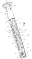
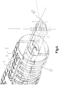
- Figures 1 , 2 and 3 show an elongate plug 1 consisting of a pin-like body 2 with a longitudinal bore 3 for receiving a nail, screw or the like (not shown) therein.
- Body 2 is manufactured from one piece of polyamide and consists of three parts: an insertion outer end A, an expansion part B and an outer end C remote from the insertion outer end.
- body 2 is equipped with lips 4 of the first type and lips 5 of the second type. Lips 4,5 of both types can pivot or swivel about pivot or swivel axes 6 extending parallel to the longitudinal direction of body 2.
- a hole is first drilled in a surface of for instance concrete, after which plug 1 is arranged manually or with a hammer in the pre-drilled hole.
- a screw for instance (not shown) is subsequently inserted into longitudinal bore 3 and then screwed into body 2.
- Lips 4, 5 of both types will as a result pivot or swivel in expansion part B from a rest position, in which lips 4,5 extend in the outer surface of body 2, and an active position in which lips 4,5 protrude outward relative to the outer surface of body 2.
- the lips 4,5 of both types will hereby engage fixedly by means of expansion in the concrete around the pre-drilled hole and thus anchor plug 1 in the hole.
- the lips 4 of the first type can pivot about the pivot axes 6 by means of expansion forces in the same direction as a screw-in direction of the screw, while lips 5 of the second type can pivot about pivot axes 6 in a direction opposite to the screw-in direction of the screw.
- Body 2 is hereby secured in both directions. Lips 4,5 of both types are otherwise formed by incisions 7 in body 2 in the form of staples, wherein lips 4 of the first type on the one hand and lips 5 of the second type on the other are arranged offset opposite each other in body 2.
- Also arranged in body 2 at the position of expansion part B are grooves 8 which extend transversely of the longitudinal direction of body 2 and which serve to receive drilling dust therein. A locally easier deformability is hereby also realized to enable better engagement in grooves of the surface via expansion forces.
- the body is provided at the position of expansion part B with outward extending wings 9.
- Each wing 9 has an oblique side 10 oriented toward the screw-in direction of the screw and a standing side 11 oriented away from the screw-in direction of the screw. The body is thus locked in a direction opposite to the screw-in direction. Wings 9 narrow toward the insertion outer end A of body 2.
- Body 2 likewise comprises at the position of expansion part B outward extending ribs 12 for the purpose of securing body 2 in the hole.
- body 2 has an insertion outer end A narrowing toward the outside.
- the symmetrical insertion outer end A has four resilient parts or tongues 13 of similar form provided with grooves 14 extending transversely of the longitudinal direction of the body for the purpose of receiving drilling dust therein and for realizing a better local deformability.
- the outer end C remote from insertion outer end A comprises wings 15 of a type other than that of wings 9, i.e. each wing 15 likewise has an oblique side 16 oriented toward a screw-in direction of the screw as well as a standing side 17 oriented away from the screw-in direction of the screw.
- outer end C comprises a standing flange in order to prevent the possibility of plug 1 being inserted too far into the hole.
- the flange also serves as cold bridge resistance.
- the longitudinal bore 3 in body 2 has an elliptical cross-section 18 at the position of expansion part B.
- the elliptical form is designed to enable forces to be guided in controlled manner in four directions (laterally and upward and downward), while the elliptical form in part A runs conically.
- FIG. 7 body 2 is provided with two protrusions 19,20 which are arranged at a distance from each other and which extend inwardly into the longitudinal bore. Protrusions 19, 20 serve to prevent an axial impact displacement (in part B) of the screw in longitudinal bore 3 of body 2.
- the distance 1.9,20 between the protrusions is equal to a pitch of the screw.
- the angle is likewise equal to the applied pitch.
Landscapes
- Engineering & Computer Science (AREA)
- General Engineering & Computer Science (AREA)
- Mechanical Engineering (AREA)
- Dowels (AREA)
- Percussive Tools And Related Accessories (AREA)
Claims (13)
- Länglicher Dübel (1), der mit einem stiftartigen Körper (2) mit einer länglichen Bohrung (3) zur Aufnahme eines Nagels, einer Schraube oder Ähnlichem darin versehen ist, wobei der Körper (2) aus einem Stück hergestellt ist und entlang wenigstens eines Teils seiner Länge mit Lippen (4, 5) versehen ist, die zwischen einer Ruheposition, in der die Lippen (4, 5) im Wesentlichen in der Außenoberfläche des Körpers (2) liegen oder sich relativ zu der Außenoberfläche des Körpers (2) einwärts erstrecken, und einer aktiven Position, in der die Lippen (4, 5) sich relativ zu der Außenoberfläche des Körpers (2) auswärts erstrecken, schwenkbar ist, wobei die Lippen (4, 5) um eine Drehachse, die sich parallel zu der Längsrichtung des länglichen Dübels (1) erstreckt, schwenkbar sind,
dadurch gekennzeichnet, dass die Lippen (4, 5) Lippen (4) der ersten Art, die nach dem Einsetzen des Nagels, der Schraube oder Ähnlichem in die Bohrung im Uhrzeigersinn um die Drehachse schwenkbar sind, und Lippen (5) der zweiten Art aufweisen, die nach dem Einsetzen des Nagels, der Schraube oder Ähnlichem in die Bohrung im Gegenuhrzeigersinn um die Drehachse schwenkbar sind, und dass die Lippen (4) der ersten Art einerseits und die Lippen (5) der zweiten Art anderseits entgegengesetzt zueinander versetzt in dem Körper (2) angeordnet sind. - Länglicher Dübel (1) nach Anspruch 1, wobei die Lippen (4, 5) in dem Körper durch klammerartige Einschnitte (7) in dem Körper (2) ausgebildet sind.
- Länglicher Dübel (1) nach Anspruch 1 oder 2, wobei die Längsbohrung (3) in dem Körper an der Position seines Teils (B), der mit den Lippen (4, 5) versehen ist, einen ovalen, vorzugsweise elliptischen Querschnitt (18), aufweist.
- Länglicher Dübel (1) nach einem der vorhergehenden Ansprüche 1 - 3, wobei der Teil (B) des Körpers (2), der mit den Lippen (4, 5) versehen ist, Nuten (8) aufweist, die sich zu dem Zweck, Bohrstaub darin aufzunehmen, quer zu der Längsrichtung des länglichen Dübels (1) erstrecken.
- Länglicher Dübel (1) nach einem der vorhergehenden Ansprüche 1 - 4, wobei der Körper (2) wenigstens über einen Teil seiner Länge mit sich auswärts erstreckenden Flügeln (9) versehen ist, die jeweils eine schräge Seite (10), die in Richtung einer Einschraubrichtung der Schraube oder Ähnlichem in der länglichen Bohrung (3) des Körpers (2) orientiert sind, und eine stehende Seite (11), die weg von der Einschraubrichtung des Nagels, der Schraube oder Ähnlichem in der länglichen Bohrung (3) des Körpers (2) orientiert ist, aufweisen, und wobei die Flügel (9) sich in Richtung eines äußeren Einsetzendes (A) des länglichen Dübels (1) verschmälern.
- Länglicher Dübel (1) nach Anspruch 5, wobei die Flügel (9) auf einem Teil (C) des Körpers (2) entfernt von einem äußeren Einsetzende (A) des länglichen Dübels (1) und/oder einem mittleren Teil (B) des Körpers (2) angeordnet sind.
- Länglicher Dübel (1) nach einem der vorhergehenden Ansprüche 1 - 6, wobei der Körper (2) entlang wenigstens eines Teils seiner Länge mit sich auswärts erstreckenden Rippen (12) versehen ist.
- Länglicher Dübel (1) nach Anspruch 5, 6 oder 7, wobei der Teil (B) des Körpers (2), der mit den Lippen (4, 5) versehen ist, auch die Flügel (9) und die Rippen (12) aufweist.
- Länglicher Dübel (1) nach einem der vorhergehenden Ansprüche 1 - 8, wobei der Körper (2) sich in Richtung eines äußeren Einsetzendes (A) des länglichen Dübels (1) verschmälert.
- Länglicher Dübel (1) nach Anspruch 9, wobei das äußere Einsetzende (A) des länglichen Dübels (1) verschiedene elastische Teile (13) aufweist.
- Länglicher Dübel (1) nach Anspruch 10, wobei die Teile (13) mit Nuten (14) versehen sind, die sich dem Zweck, Bohrstaub darin aufzunehmen, quer zu der Längsrichtung des länglichen Dübels erstrecken.
- Länglicher Dübel (1) nach einem der vorhergehenden Ansprüche 1 - 11, wobei der Körper (2) nahe seinem äußeren Ende (C) entfernt von einem äußeren Einsetzende (A) des länglichen Dübels (1) mit zwei Vorsprüngen (19, 20) versehen ist, die in einem Abstand voneinander angeordnet sind und die sich einwärts in die Längsbohrung (3) erstrecken, wobei die Vorsprünge (19, 20) konfiguriert sind, um eine axiale Stoßverschiebung der Schraube oder Ähnlichem in der Längsbohrung (3) des Körpers (2) zu verhindern.
- Länglicher Dübel (1) nach Anspruch 12, wobei der Abstand zwischen den Vorsprüngen (19, 20) gleich einer Gewindesteigung einer in der Längsbohrung (3) aufgenommenen Schraube ist.
Applications Claiming Priority (2)
| Application Number | Priority Date | Filing Date | Title |
|---|---|---|---|
| NL2011125A NL2011125C2 (nl) | 2013-07-09 | 2013-07-09 | Langwerpige plug voorzien van een penvormig lijf met een longitudinale boring voor het daarin opnemen van een nagel, schroef of dergelijke. |
| PCT/NL2014/050440 WO2015005773A1 (en) | 2013-07-09 | 2014-07-03 | Elongated plug provided with a pin-shaped body haying a longitudinal bore for receiving a nail, screw or the like therein |
Publications (2)
| Publication Number | Publication Date |
|---|---|
| EP2941573A1 EP2941573A1 (de) | 2015-11-11 |
| EP2941573B1 true EP2941573B1 (de) | 2020-06-10 |
Family
ID=51205539
Family Applications (1)
| Application Number | Title | Priority Date | Filing Date |
|---|---|---|---|
| EP14739575.0A Active EP2941573B1 (de) | 2013-07-09 | 2014-07-03 | Länglicher stecker mit einem stiftartigen körper mit einer länglichen bohrung zur aufnahme eines nagels, einer schraube oder dergleichen |
Country Status (4)
| Country | Link |
|---|---|
| EP (1) | EP2941573B1 (de) |
| BR (1) | BR112015032924B1 (de) |
| NL (1) | NL2011125C2 (de) |
| WO (1) | WO2015005773A1 (de) |
Citations (2)
| Publication number | Priority date | Publication date | Assignee | Title |
|---|---|---|---|---|
| EP0934469B1 (de) * | 1996-11-15 | 2002-02-13 | Fischerwerke Arthur Fischer GmbH & Co. KG | Schraubenanker |
| WO2014079546A1 (de) * | 2012-11-21 | 2014-05-30 | Fischerwerke Gmbh & Co. Kg | Spreizdübel |
Family Cites Families (4)
| Publication number | Priority date | Publication date | Assignee | Title |
|---|---|---|---|---|
| AT292280B (de) * | 1968-08-30 | 1971-08-25 | Langensiepen Kg M | Dübel |
| DE3317937A1 (de) * | 1982-11-10 | 1984-05-10 | Hilti Ag, Schaan | Huelsenfoermiger spreizduebel |
| DE3416797A1 (de) * | 1984-05-07 | 1985-11-07 | Hilti Ag, Schaan | Kunststoff-spreizduebel |
| DE19825689A1 (de) * | 1998-06-09 | 1999-12-16 | Adolf Wuerth Gmbh & Co Kg | Rahmendübel |
-
2013
- 2013-07-09 NL NL2011125A patent/NL2011125C2/nl not_active IP Right Cessation
-
2014
- 2014-07-03 WO PCT/NL2014/050440 patent/WO2015005773A1/en not_active Ceased
- 2014-07-03 BR BR112015032924-1A patent/BR112015032924B1/pt active IP Right Grant
- 2014-07-03 EP EP14739575.0A patent/EP2941573B1/de active Active
Patent Citations (2)
| Publication number | Priority date | Publication date | Assignee | Title |
|---|---|---|---|---|
| EP0934469B1 (de) * | 1996-11-15 | 2002-02-13 | Fischerwerke Arthur Fischer GmbH & Co. KG | Schraubenanker |
| WO2014079546A1 (de) * | 2012-11-21 | 2014-05-30 | Fischerwerke Gmbh & Co. Kg | Spreizdübel |
Also Published As
| Publication number | Publication date |
|---|---|
| WO2015005773A1 (en) | 2015-01-15 |
| WO2015005773A9 (en) | 2015-03-12 |
| EP2941573A1 (de) | 2015-11-11 |
| BR112015032924B1 (pt) | 2021-04-06 |
| NL2011125C2 (nl) | 2015-01-12 |
Similar Documents
| Publication | Publication Date | Title |
|---|---|---|
| US5224805A (en) | Anchoring plug | |
| JP6071412B2 (ja) | ロックアセンブリ、多軸骨固定装置、および骨または脊椎を安定させる方法 | |
| EP0165674B1 (de) | Einsatzbuchse für poröse Wände | |
| US7959379B2 (en) | Bolt anchor | |
| EP2580486B1 (de) | Schraube mit doppelter gewindekante | |
| CA2392892A1 (en) | Wood screw | |
| US20190309783A1 (en) | Toolless screw type fastener | |
| EP3227569B1 (de) | Schwenkbarer aufhänger | |
| US20190032694A1 (en) | Fastener with transition zone and method of use | |
| US20170030394A1 (en) | Fastener with transition zone and method of use | |
| US20040170484A1 (en) | Striking plug | |
| US9080291B2 (en) | Embedded receiver for fasteners | |
| US20100230909A1 (en) | Adapter for self-drilling, chemically anchorable fastening element | |
| US20060110237A1 (en) | Spline drive fastener system | |
| EP2265778B1 (de) | Wandanker | |
| WO2015005773A1 (en) | Elongated plug provided with a pin-shaped body haying a longitudinal bore for receiving a nail, screw or the like therein | |
| GB2453010A (en) | Plasterboard anchor | |
| EP2800911B1 (de) | Blindbolzen | |
| JP6172635B2 (ja) | 手摺取付構造 | |
| US20170241458A1 (en) | Masonry anchor of the expansion type | |
| EP1977118B1 (de) | Anker für sprödes material | |
| US20070140811A1 (en) | High strength screw head and driver bit | |
| EP3260710B1 (de) | Maureranker mit spreizkörper | |
| CN205823875U (zh) | 一种新型螺钉 | |
| KR20190090909A (ko) | 스크류 앵커용 플러그 |
Legal Events
| Date | Code | Title | Description |
|---|---|---|---|
| PUAI | Public reference made under article 153(3) epc to a published international application that has entered the european phase |
Free format text: ORIGINAL CODE: 0009012 |
|
| 17P | Request for examination filed |
Effective date: 20150804 |
|
| AK | Designated contracting states |
Kind code of ref document: A1 Designated state(s): AL AT BE BG CH CY CZ DE DK EE ES FI FR GB GR HR HU IE IS IT LI LT LU LV MC MK MT NL NO PL PT RO RS SE SI SK SM TR |
|
| AX | Request for extension of the european patent |
Extension state: BA ME |
|
| TPAC | Observations filed by third parties |
Free format text: ORIGINAL CODE: EPIDOSNTIPA |
|
| RIN1 | Information on inventor provided before grant (corrected) |
Inventor name: BALEN, FRANK PIETER JACOBUS Inventor name: JANSEN, ING. STEFAN |
|
| 17Q | First examination report despatched |
Effective date: 20160713 |
|
| DAX | Request for extension of the european patent (deleted) | ||
| STAA | Information on the status of an ep patent application or granted ep patent |
Free format text: STATUS: EXAMINATION IS IN PROGRESS |
|
| GRAP | Despatch of communication of intention to grant a patent |
Free format text: ORIGINAL CODE: EPIDOSNIGR1 |
|
| STAA | Information on the status of an ep patent application or granted ep patent |
Free format text: STATUS: GRANT OF PATENT IS INTENDED |
|
| RAP1 | Party data changed (applicant data changed or rights of an application transferred) |
Owner name: JANSEN, STEFAN Owner name: BALEN, FRANK PIETER JACOBUS Owner name: MIREKAJA A.G. |
|
| INTG | Intention to grant announced |
Effective date: 20200204 |
|
| GRAS | Grant fee paid |
Free format text: ORIGINAL CODE: EPIDOSNIGR3 |
|
| GRAA | (expected) grant |
Free format text: ORIGINAL CODE: 0009210 |
|
| STAA | Information on the status of an ep patent application or granted ep patent |
Free format text: STATUS: THE PATENT HAS BEEN GRANTED |
|
| AK | Designated contracting states |
Kind code of ref document: B1 Designated state(s): AL AT BE BG CH CY CZ DE DK EE ES FI FR GB GR HR HU IE IS IT LI LT LU LV MC MK MT NL NO PL PT RO RS SE SI SK SM TR |
|
| REG | Reference to a national code |
Ref country code: GB Ref legal event code: FG4D |
|
| REG | Reference to a national code |
Ref country code: AT Ref legal event code: REF Ref document number: 1279427 Country of ref document: AT Kind code of ref document: T Effective date: 20200615 Ref country code: CH Ref legal event code: EP |
|
| REG | Reference to a national code |
Ref country code: DE Ref legal event code: R096 Ref document number: 602014066474 Country of ref document: DE |
|
| REG | Reference to a national code |
Ref country code: IE Ref legal event code: FG4D |
|
| REG | Reference to a national code |
Ref country code: NL Ref legal event code: FP |
|
| REG | Reference to a national code |
Ref country code: LT Ref legal event code: MG4D |
|
| PG25 | Lapsed in a contracting state [announced via postgrant information from national office to epo] |
Ref country code: LT Free format text: LAPSE BECAUSE OF FAILURE TO SUBMIT A TRANSLATION OF THE DESCRIPTION OR TO PAY THE FEE WITHIN THE PRESCRIBED TIME-LIMIT Effective date: 20200610 Ref country code: GR Free format text: LAPSE BECAUSE OF FAILURE TO SUBMIT A TRANSLATION OF THE DESCRIPTION OR TO PAY THE FEE WITHIN THE PRESCRIBED TIME-LIMIT Effective date: 20200911 Ref country code: NO Free format text: LAPSE BECAUSE OF FAILURE TO SUBMIT A TRANSLATION OF THE DESCRIPTION OR TO PAY THE FEE WITHIN THE PRESCRIBED TIME-LIMIT Effective date: 20200910 Ref country code: FI Free format text: LAPSE BECAUSE OF FAILURE TO SUBMIT A TRANSLATION OF THE DESCRIPTION OR TO PAY THE FEE WITHIN THE PRESCRIBED TIME-LIMIT Effective date: 20200610 Ref country code: SE Free format text: LAPSE BECAUSE OF FAILURE TO SUBMIT A TRANSLATION OF THE DESCRIPTION OR TO PAY THE FEE WITHIN THE PRESCRIBED TIME-LIMIT Effective date: 20200610 |
|
| PG25 | Lapsed in a contracting state [announced via postgrant information from national office to epo] |
Ref country code: HR Free format text: LAPSE BECAUSE OF FAILURE TO SUBMIT A TRANSLATION OF THE DESCRIPTION OR TO PAY THE FEE WITHIN THE PRESCRIBED TIME-LIMIT Effective date: 20200610 Ref country code: BG Free format text: LAPSE BECAUSE OF FAILURE TO SUBMIT A TRANSLATION OF THE DESCRIPTION OR TO PAY THE FEE WITHIN THE PRESCRIBED TIME-LIMIT Effective date: 20200910 Ref country code: RS Free format text: LAPSE BECAUSE OF FAILURE TO SUBMIT A TRANSLATION OF THE DESCRIPTION OR TO PAY THE FEE WITHIN THE PRESCRIBED TIME-LIMIT Effective date: 20200610 Ref country code: LV Free format text: LAPSE BECAUSE OF FAILURE TO SUBMIT A TRANSLATION OF THE DESCRIPTION OR TO PAY THE FEE WITHIN THE PRESCRIBED TIME-LIMIT Effective date: 20200610 |
|
| REG | Reference to a national code |
Ref country code: CH Ref legal event code: NV Representative=s name: ARNOLD AND SIEDSMA AG, CH Ref country code: AT Ref legal event code: MK05 Ref document number: 1279427 Country of ref document: AT Kind code of ref document: T Effective date: 20200610 |
|
| PG25 | Lapsed in a contracting state [announced via postgrant information from national office to epo] |
Ref country code: AL Free format text: LAPSE BECAUSE OF FAILURE TO SUBMIT A TRANSLATION OF THE DESCRIPTION OR TO PAY THE FEE WITHIN THE PRESCRIBED TIME-LIMIT Effective date: 20200610 |
|
| PG25 | Lapsed in a contracting state [announced via postgrant information from national office to epo] |
Ref country code: ES Free format text: LAPSE BECAUSE OF FAILURE TO SUBMIT A TRANSLATION OF THE DESCRIPTION OR TO PAY THE FEE WITHIN THE PRESCRIBED TIME-LIMIT Effective date: 20200610 Ref country code: PT Free format text: LAPSE BECAUSE OF FAILURE TO SUBMIT A TRANSLATION OF THE DESCRIPTION OR TO PAY THE FEE WITHIN THE PRESCRIBED TIME-LIMIT Effective date: 20201012 Ref country code: AT Free format text: LAPSE BECAUSE OF FAILURE TO SUBMIT A TRANSLATION OF THE DESCRIPTION OR TO PAY THE FEE WITHIN THE PRESCRIBED TIME-LIMIT Effective date: 20200610 Ref country code: EE Free format text: LAPSE BECAUSE OF FAILURE TO SUBMIT A TRANSLATION OF THE DESCRIPTION OR TO PAY THE FEE WITHIN THE PRESCRIBED TIME-LIMIT Effective date: 20200610 Ref country code: SM Free format text: LAPSE BECAUSE OF FAILURE TO SUBMIT A TRANSLATION OF THE DESCRIPTION OR TO PAY THE FEE WITHIN THE PRESCRIBED TIME-LIMIT Effective date: 20200610 Ref country code: CZ Free format text: LAPSE BECAUSE OF FAILURE TO SUBMIT A TRANSLATION OF THE DESCRIPTION OR TO PAY THE FEE WITHIN THE PRESCRIBED TIME-LIMIT Effective date: 20200610 Ref country code: IT Free format text: LAPSE BECAUSE OF FAILURE TO SUBMIT A TRANSLATION OF THE DESCRIPTION OR TO PAY THE FEE WITHIN THE PRESCRIBED TIME-LIMIT Effective date: 20200610 Ref country code: RO Free format text: LAPSE BECAUSE OF FAILURE TO SUBMIT A TRANSLATION OF THE DESCRIPTION OR TO PAY THE FEE WITHIN THE PRESCRIBED TIME-LIMIT Effective date: 20200610 |
|
| PG25 | Lapsed in a contracting state [announced via postgrant information from national office to epo] |
Ref country code: IS Free format text: LAPSE BECAUSE OF FAILURE TO SUBMIT A TRANSLATION OF THE DESCRIPTION OR TO PAY THE FEE WITHIN THE PRESCRIBED TIME-LIMIT Effective date: 20201010 Ref country code: PL Free format text: LAPSE BECAUSE OF FAILURE TO SUBMIT A TRANSLATION OF THE DESCRIPTION OR TO PAY THE FEE WITHIN THE PRESCRIBED TIME-LIMIT Effective date: 20200610 Ref country code: SK Free format text: LAPSE BECAUSE OF FAILURE TO SUBMIT A TRANSLATION OF THE DESCRIPTION OR TO PAY THE FEE WITHIN THE PRESCRIBED TIME-LIMIT Effective date: 20200610 |
|
| REG | Reference to a national code |
Ref country code: DE Ref legal event code: R097 Ref document number: 602014066474 Country of ref document: DE |
|
| PG25 | Lapsed in a contracting state [announced via postgrant information from national office to epo] |
Ref country code: MC Free format text: LAPSE BECAUSE OF FAILURE TO SUBMIT A TRANSLATION OF THE DESCRIPTION OR TO PAY THE FEE WITHIN THE PRESCRIBED TIME-LIMIT Effective date: 20200610 |
|
| PLBE | No opposition filed within time limit |
Free format text: ORIGINAL CODE: 0009261 |
|
| STAA | Information on the status of an ep patent application or granted ep patent |
Free format text: STATUS: NO OPPOSITION FILED WITHIN TIME LIMIT |
|
| PG25 | Lapsed in a contracting state [announced via postgrant information from national office to epo] |
Ref country code: LU Free format text: LAPSE BECAUSE OF NON-PAYMENT OF DUE FEES Effective date: 20200703 Ref country code: DK Free format text: LAPSE BECAUSE OF FAILURE TO SUBMIT A TRANSLATION OF THE DESCRIPTION OR TO PAY THE FEE WITHIN THE PRESCRIBED TIME-LIMIT Effective date: 20200610 Ref country code: IE Free format text: LAPSE BECAUSE OF NON-PAYMENT OF DUE FEES Effective date: 20200703 |
|
| 26N | No opposition filed |
Effective date: 20210311 |
|
| GBPC | Gb: european patent ceased through non-payment of renewal fee |
Effective date: 20200910 |
|
| PG25 | Lapsed in a contracting state [announced via postgrant information from national office to epo] |
Ref country code: SI Free format text: LAPSE BECAUSE OF FAILURE TO SUBMIT A TRANSLATION OF THE DESCRIPTION OR TO PAY THE FEE WITHIN THE PRESCRIBED TIME-LIMIT Effective date: 20200610 |
|
| PG25 | Lapsed in a contracting state [announced via postgrant information from national office to epo] |
Ref country code: GB Free format text: LAPSE BECAUSE OF NON-PAYMENT OF DUE FEES Effective date: 20200910 |
|
| PG25 | Lapsed in a contracting state [announced via postgrant information from national office to epo] |
Ref country code: TR Free format text: LAPSE BECAUSE OF FAILURE TO SUBMIT A TRANSLATION OF THE DESCRIPTION OR TO PAY THE FEE WITHIN THE PRESCRIBED TIME-LIMIT Effective date: 20200610 Ref country code: MT Free format text: LAPSE BECAUSE OF FAILURE TO SUBMIT A TRANSLATION OF THE DESCRIPTION OR TO PAY THE FEE WITHIN THE PRESCRIBED TIME-LIMIT Effective date: 20200610 Ref country code: CY Free format text: LAPSE BECAUSE OF FAILURE TO SUBMIT A TRANSLATION OF THE DESCRIPTION OR TO PAY THE FEE WITHIN THE PRESCRIBED TIME-LIMIT Effective date: 20200610 |
|
| PG25 | Lapsed in a contracting state [announced via postgrant information from national office to epo] |
Ref country code: MK Free format text: LAPSE BECAUSE OF FAILURE TO SUBMIT A TRANSLATION OF THE DESCRIPTION OR TO PAY THE FEE WITHIN THE PRESCRIBED TIME-LIMIT Effective date: 20200610 |
|
| P01 | Opt-out of the competence of the unified patent court (upc) registered |
Effective date: 20230518 |
|
| PGFP | Annual fee paid to national office [announced via postgrant information from national office to epo] |
Ref country code: NL Payment date: 20250726 Year of fee payment: 12 |
|
| PGFP | Annual fee paid to national office [announced via postgrant information from national office to epo] |
Ref country code: DE Payment date: 20250729 Year of fee payment: 12 |
|
| PGFP | Annual fee paid to national office [announced via postgrant information from national office to epo] |
Ref country code: BE Payment date: 20250728 Year of fee payment: 12 |
|
| PGFP | Annual fee paid to national office [announced via postgrant information from national office to epo] |
Ref country code: FR Payment date: 20250725 Year of fee payment: 12 |
|
| PGFP | Annual fee paid to national office [announced via postgrant information from national office to epo] |
Ref country code: CH Payment date: 20250801 Year of fee payment: 12 |