EP3227559B1 - Elektronische wandlereinheit für eine pumpe und verfahren zur kommunikation mit der elektronischen wandlereinheit - Google Patents
Elektronische wandlereinheit für eine pumpe und verfahren zur kommunikation mit der elektronischen wandlereinheit Download PDFInfo
- Publication number
- EP3227559B1 EP3227559B1 EP15804512.0A EP15804512A EP3227559B1 EP 3227559 B1 EP3227559 B1 EP 3227559B1 EP 15804512 A EP15804512 A EP 15804512A EP 3227559 B1 EP3227559 B1 EP 3227559B1
- Authority
- EP
- European Patent Office
- Prior art keywords
- unit
- electronic converter
- converter unit
- signal
- pump
- Prior art date
- Legal status (The legal status is an assumption and is not a legal conclusion. Google has not performed a legal analysis and makes no representation as to the accuracy of the status listed.)
- Active
Links
- 230000006854 communication Effects 0.000 title claims description 130
- 238000004891 communication Methods 0.000 title claims description 130
- 230000003287 optical effect Effects 0.000 claims description 44
- 238000010438 heat treatment Methods 0.000 claims description 29
- 238000000034 method Methods 0.000 claims description 29
- 230000005540 biological transmission Effects 0.000 claims description 14
- 230000003068 static effect Effects 0.000 claims description 7
- 230000001360 synchronised effect Effects 0.000 claims description 3
- 239000010410 layer Substances 0.000 description 24
- 239000004020 conductor Substances 0.000 description 18
- 230000008569 process Effects 0.000 description 8
- 238000004519 manufacturing process Methods 0.000 description 6
- 238000013461 design Methods 0.000 description 5
- 238000005516 engineering process Methods 0.000 description 5
- 238000012545 processing Methods 0.000 description 5
- 230000008054 signal transmission Effects 0.000 description 5
- 230000001276 controlling effect Effects 0.000 description 4
- 239000012530 fluid Substances 0.000 description 4
- 239000011521 glass Substances 0.000 description 4
- 239000007788 liquid Substances 0.000 description 4
- 230000000007 visual effect Effects 0.000 description 4
- 239000000853 adhesive Substances 0.000 description 3
- 230000001070 adhesive effect Effects 0.000 description 3
- 230000008901 benefit Effects 0.000 description 3
- 230000007175 bidirectional communication Effects 0.000 description 3
- 229910001369 Brass Inorganic materials 0.000 description 2
- RYGMFSIKBFXOCR-UHFFFAOYSA-N Copper Chemical compound [Cu] RYGMFSIKBFXOCR-UHFFFAOYSA-N 0.000 description 2
- 239000002390 adhesive tape Substances 0.000 description 2
- 239000010951 brass Substances 0.000 description 2
- 238000004422 calculation algorithm Methods 0.000 description 2
- 238000006243 chemical reaction Methods 0.000 description 2
- 229910052802 copper Inorganic materials 0.000 description 2
- 239000010949 copper Substances 0.000 description 2
- 238000005265 energy consumption Methods 0.000 description 2
- 210000000497 foam cell Anatomy 0.000 description 2
- 239000002184 metal Substances 0.000 description 2
- 229910052751 metal Inorganic materials 0.000 description 2
- 230000009467 reduction Effects 0.000 description 2
- 230000001105 regulatory effect Effects 0.000 description 2
- 238000012360 testing method Methods 0.000 description 2
- 238000012546 transfer Methods 0.000 description 2
- NIXOWILDQLNWCW-UHFFFAOYSA-N acrylic acid group Chemical group C(C=C)(=O)O NIXOWILDQLNWCW-UHFFFAOYSA-N 0.000 description 1
- 230000004075 alteration Effects 0.000 description 1
- 230000003321 amplification Effects 0.000 description 1
- 230000008859 change Effects 0.000 description 1
- 238000001514 detection method Methods 0.000 description 1
- 230000023077 detection of light stimulus Effects 0.000 description 1
- 230000009977 dual effect Effects 0.000 description 1
- 239000000284 extract Substances 0.000 description 1
- 230000006698 induction Effects 0.000 description 1
- 230000001939 inductive effect Effects 0.000 description 1
- 238000012423 maintenance Methods 0.000 description 1
- 238000012986 modification Methods 0.000 description 1
- 230000004048 modification Effects 0.000 description 1
- 238000012544 monitoring process Methods 0.000 description 1
- 238000003199 nucleic acid amplification method Methods 0.000 description 1
- 239000002356 single layer Substances 0.000 description 1
- 230000005236 sound signal Effects 0.000 description 1
- XLYOFNOQVPJJNP-UHFFFAOYSA-N water Substances O XLYOFNOQVPJJNP-UHFFFAOYSA-N 0.000 description 1
- 230000003313 weakening effect Effects 0.000 description 1
Images


Classifications
-
- F—MECHANICAL ENGINEERING; LIGHTING; HEATING; WEAPONS; BLASTING
- F24—HEATING; RANGES; VENTILATING
- F24D—DOMESTIC- OR SPACE-HEATING SYSTEMS, e.g. CENTRAL HEATING SYSTEMS; DOMESTIC HOT-WATER SUPPLY SYSTEMS; ELEMENTS OR COMPONENTS THEREFOR
- F24D19/00—Details
- F24D19/10—Arrangement or mounting of control or safety devices
- F24D19/1006—Arrangement or mounting of control or safety devices for water heating systems
- F24D19/1009—Arrangement or mounting of control or safety devices for water heating systems for central heating
- F24D19/1012—Arrangement or mounting of control or safety devices for water heating systems for central heating by regulating the speed of a pump
-
- F—MECHANICAL ENGINEERING; LIGHTING; HEATING; WEAPONS; BLASTING
- F04—POSITIVE - DISPLACEMENT MACHINES FOR LIQUIDS; PUMPS FOR LIQUIDS OR ELASTIC FLUIDS
- F04D—NON-POSITIVE-DISPLACEMENT PUMPS
- F04D13/00—Pumping installations or systems
- F04D13/02—Units comprising pumps and their driving means
- F04D13/06—Units comprising pumps and their driving means the pump being electrically driven
- F04D13/0686—Mechanical details of the pump control unit
-
- F—MECHANICAL ENGINEERING; LIGHTING; HEATING; WEAPONS; BLASTING
- F04—POSITIVE - DISPLACEMENT MACHINES FOR LIQUIDS; PUMPS FOR LIQUIDS OR ELASTIC FLUIDS
- F04D—NON-POSITIVE-DISPLACEMENT PUMPS
- F04D15/00—Control, e.g. regulation, of pumps, pumping installations or systems
- F04D15/0066—Control, e.g. regulation, of pumps, pumping installations or systems by changing the speed, e.g. of the driving engine
-
- F—MECHANICAL ENGINEERING; LIGHTING; HEATING; WEAPONS; BLASTING
- F04—POSITIVE - DISPLACEMENT MACHINES FOR LIQUIDS; PUMPS FOR LIQUIDS OR ELASTIC FLUIDS
- F04D—NON-POSITIVE-DISPLACEMENT PUMPS
- F04D15/00—Control, e.g. regulation, of pumps, pumping installations or systems
- F04D15/0088—Testing machines
-
- F—MECHANICAL ENGINEERING; LIGHTING; HEATING; WEAPONS; BLASTING
- F24—HEATING; RANGES; VENTILATING
- F24D—DOMESTIC- OR SPACE-HEATING SYSTEMS, e.g. CENTRAL HEATING SYSTEMS; DOMESTIC HOT-WATER SUPPLY SYSTEMS; ELEMENTS OR COMPONENTS THEREFOR
- F24D19/00—Details
- F24D19/10—Arrangement or mounting of control or safety devices
- F24D19/1006—Arrangement or mounting of control or safety devices for water heating systems
- F24D19/1009—Arrangement or mounting of control or safety devices for water heating systems for central heating
- F24D19/1015—Arrangement or mounting of control or safety devices for water heating systems for central heating using a valve or valves
-
- F—MECHANICAL ENGINEERING; LIGHTING; HEATING; WEAPONS; BLASTING
- F24—HEATING; RANGES; VENTILATING
- F24D—DOMESTIC- OR SPACE-HEATING SYSTEMS, e.g. CENTRAL HEATING SYSTEMS; DOMESTIC HOT-WATER SUPPLY SYSTEMS; ELEMENTS OR COMPONENTS THEREFOR
- F24D19/00—Details
- F24D19/10—Arrangement or mounting of control or safety devices
- F24D19/1006—Arrangement or mounting of control or safety devices for water heating systems
- F24D19/1009—Arrangement or mounting of control or safety devices for water heating systems for central heating
- F24D19/1048—Counting of energy consumption
-
- F—MECHANICAL ENGINEERING; LIGHTING; HEATING; WEAPONS; BLASTING
- F24—HEATING; RANGES; VENTILATING
- F24D—DOMESTIC- OR SPACE-HEATING SYSTEMS, e.g. CENTRAL HEATING SYSTEMS; DOMESTIC HOT-WATER SUPPLY SYSTEMS; ELEMENTS OR COMPONENTS THEREFOR
- F24D3/00—Hot-water central heating systems
- F24D3/10—Feed-line arrangements, e.g. providing for heat-accumulator tanks, expansion tanks ; Hydraulic components of a central heating system
-
- H—ELECTRICITY
- H04—ELECTRIC COMMUNICATION TECHNIQUE
- H04L—TRANSMISSION OF DIGITAL INFORMATION, e.g. TELEGRAPHIC COMMUNICATION
- H04L12/00—Data switching networks
- H04L12/02—Details
- H04L12/16—Arrangements for providing special services to substations
- H04L12/18—Arrangements for providing special services to substations for broadcast or conference, e.g. multicast
- H04L12/1854—Arrangements for providing special services to substations for broadcast or conference, e.g. multicast with non-centralised forwarding system, e.g. chaincast
-
- H—ELECTRICITY
- H04—ELECTRIC COMMUNICATION TECHNIQUE
- H04W—WIRELESS COMMUNICATION NETWORKS
- H04W84/00—Network topologies
- H04W84/18—Self-organising networks, e.g. ad-hoc networks or sensor networks
-
- H—ELECTRICITY
- H04—ELECTRIC COMMUNICATION TECHNIQUE
- H04Q—SELECTING
- H04Q2209/00—Arrangements in telecontrol or telemetry systems
-
- H—ELECTRICITY
- H04—ELECTRIC COMMUNICATION TECHNIQUE
- H04Q—SELECTING
- H04Q2209/00—Arrangements in telecontrol or telemetry systems
- H04Q2209/40—Arrangements in telecontrol or telemetry systems using a wireless architecture
-
- H—ELECTRICITY
- H04—ELECTRIC COMMUNICATION TECHNIQUE
- H04Q—SELECTING
- H04Q9/00—Arrangements in telecontrol or telemetry systems for selectively calling a substation from a main station, in which substation desired apparatus is selected for applying a control signal thereto or for obtaining measured values therefrom
-
- Y—GENERAL TAGGING OF NEW TECHNOLOGICAL DEVELOPMENTS; GENERAL TAGGING OF CROSS-SECTIONAL TECHNOLOGIES SPANNING OVER SEVERAL SECTIONS OF THE IPC; TECHNICAL SUBJECTS COVERED BY FORMER USPC CROSS-REFERENCE ART COLLECTIONS [XRACs] AND DIGESTS
- Y02—TECHNOLOGIES OR APPLICATIONS FOR MITIGATION OR ADAPTATION AGAINST CLIMATE CHANGE
- Y02B—CLIMATE CHANGE MITIGATION TECHNOLOGIES RELATED TO BUILDINGS, e.g. HOUSING, HOUSE APPLIANCES OR RELATED END-USER APPLICATIONS
- Y02B30/00—Energy efficient heating, ventilation or air conditioning [HVAC]
- Y02B30/70—Efficient control or regulation technologies, e.g. for control of refrigerant flow, motor or heating
Definitions
- the present invention relates to an electronic converter unit for use with a pump unit, such as a centrifugal pump.
- the invention further relates to a kit of parts comprising a pump unit and at least two electronic converter units.
- the invention additionally relates to a system comprising a pump unit, at least two electronic converter units, and an external communication device, such as a smart phone.
- the invention relates to a method for communicating with the electronic converter unit.
- Circulation pumps are often intended to deliver a specific head and flow rate at given circumstances in order to meet particular requirements.
- the pump units may be controlled according to different control patterns by changing one or more drive parameters. This may be done by the user of the pump by use of input means provided on the pump itself, e.g. via an interface, such as a touch screen, on the pump unit.
- input means provided on the pump itself, e.g. via an interface, such as a touch screen, on the pump unit.
- providing a pump unit with a display or a touch screen adds costs to the production price of the pump unit and thus also to the purchase price for the end consumer. Further, it entails a security risk, if anybody can gain access to the control system and to control the system to drive the pump unit at erroneous drive conditions.
- EP 1 321 912 discloses a pump unit with a control or regulating device for controlling or regulating a drive of the pump, wherein the device has a light source for emitting light, which can be used for the transmission of data to a reader device.
- WO 2013/041616 discloses a pump unit having an electrical drive motor and a control device for controlling the drive motor.
- WO 2013/117401 discloses an electric motor, which is provided with a signal device for indicating at least two different operating states.
- the signal device has six light-emitting diodes, which are connected to flash mutually offset in time from one another, when the motor is running, so that they represent the rotary motion of the motor.
- a simple diode display may provide a simple visual indication to a user, e.g. green light for correct operating conditions and red light for faulty operating conditions, it is difficult to extract more detailed information about the operating condition of the pump.
- Information about pump status can be extracted by wired transfer of information according to standardized data protocols.
- the Applicant thus manufactures and markets a product called "Grundfos Go", which is a communication solution between a centrifugal pump and a smart phone.
- the communication is done via an electronic converter unit - a dongle - which can be inserted in an input port of the smart phone or be placed remotely from the smart phone.
- the control housing of the pump comprises a built-in communication module for wireless radio frequency communication with the electronic converter unit via the GLoWPAN protocol.
- the electronic converter then converts the data from GLoWPAN format to Bluetooth® format and transmits the data to the smart phone.
- This solution has the drawback that the pump needs a relatively expensive radio frequency transmission module. Further, the transmission distance between pump, dongle and smart phone is limited. Based on these drawbacks the present invention aims at providing a simple communication solution between a pump and a smart device (such as phone or a tablet), which solution is versatile, easy to handle and gives a satisfactory transmission range.
- US 2005/0054292 discloses a method and system for transmitting, receiving, and collecting information related to a plurality of working components, such as street lamps, allows for efficient and effective monitoring and controlling of working components through short-distance radio communications at low power levels.
- a communications network includes a plurality of transceiver modules, each of which is secured and operably connected to a working component. These transceiver modules transmit and receive radio communications or "messages" representative of the status of the working component from one another in a controlled manner, with each message ultimately being directed to an area control module.
- the invention provides an electronic converter unit to be arranged external to a pump unit, wherein the pump unit includes a housing, which comprises a signal source for emitting a signal.
- the electronic converter unit comprises:
- the same communication unit i.e. the electronic converter unit
- the electronic converter unit may be used either as a converter unit or a repeater and combined the reach of the communication unit may be extended, which can be a huge benefit in for instance multi-storey houses.
- the communication units may be interchanged without impairing the signal path between the pump unit and the external communication device, such as a smart phone.
- the invention has the advantage that the pump unit does not have to be equipped with relatively expensive radio frequency communication circuitry. Instead a low cost communication solution is found by letting the electronic converter unit taking over the long distance signal transmission while the pump is equipped with relatively low cost and low range communication circuitry. In manufacturing this means a considerable cost reduction.
- the invention enables read out of internal pump parameters to the outside world with a versatile solution where a service technician can create an on-the-spot communication interface with the pump also over a long communication distance.
- the unit is in the following mostly defined as an electronic converter unit, it is clear that the invention relates to an electronic communication unit, which is configured to operate as an electronic converter unit (in the converter mode) and as a repeater (in repeater mode).
- an electronic converter unit in the converter mode
- a communication unit in the following description, there may be referred to an electronic converter unit, a communication unit, or a repeater.
- Signal converter mode is to be understood as a mode where one physical signal is converted into another physical signal, e.g. a light signal into a radio frequency signal, or as a protocol conversion from one digital protocol into another digital protocol.
- Synignal repeater mode is to be understood as a mode, where an incoming signal is repeated by the electronic converter unit, i.e. the contents of a data telegram remains the same.
- the electronic converter unit may be arranged near or at or on the pump unit and is not part of the pump unit itself.
- the electronic converter unit is configured to set itself to signal converter mode, if it detects the signal from the signal source of the pump unit. Thus, an operator merely has to position the electronic converter unit near or at the pump and it automatically sets itself up to function as a signal converter. Also, the electronic converter unit is configured to set itself to signal repeater mode, if it does not detect signals from the signal source of the pump unit. Thus, an electronic converter unit will automatically start to listen for signals to be repeated and sent from another unit, if is not arranged within the signal reach of a pump unit. The automated detection and shift into the correct mode makes it easy for the service technician using the inventive electronic converter unit. He or she does not have to program anything.
- the dual functions of the electronic converter unit may be achieved by designing two communication inputs - first and second signal detectors - into the converter unit.
- the first input is a signal input for a first type of signals such as optical signals.
- the frequency range of this input is in a low range 1 Hz to 1 MHz.
- the second input receives a wireless high frequency signal in the range from 100 MHz to 3 GHz.
- the electronic converter unit has an antenna used for both receiving and sending data.
- the electronic converter unit has one input for signals to be converted, and another input for signals to be repeated.
- the electronic converter unit in signal converter mode receives the signal from the signal source of the pump unit, which signal is to be sent to the external communication unit, and wherein the converter unit in signal repeater mode is configured to receive electrical signals from an identical converter unit and relays the electrical signal to a further identical converter unit or the external communication unit.
- the electronic converter unit operates in signal converter mode or signal repeater mode. In the latter mode several units can be connected, e.g. four units giving a wide signal range.
- the electronic converter unit is configured to send telegrams in a broadcasting mode, preferably as unidirectional communication.
- the Bluetooth® broadcasting function is preferably used instead of the commonly used bidirectional communication (Bluetooth® pairing) between two communicating units.
- Bluetooth® pairing the bidirectional communication enhances robustness in the exchange of data, tests have shown that unidirectional communication with sufficient high frequency of digital telegrams suffices to get a satisfactory result. Thereby, the service technician may save time in setting up a communication path without having to pair devices.
- the Bluetooth® Low Energy protocol also called BLE or Bluetooth® Smart or 4.0, is used in its non-connectable mode where advertise messages are broadcasted to other repeaters or handheld devices according to the invention.
- the electronic converter unit in signal repeater mode is configured to be synchronised with another identical electronic converter unit.
- a repeater may be synchronised with an electronic converter unit or another repeater to be only activated at timing instants, where the electronic converter unit or another repeater is expected to send a telegram or data package.
- the repeater only listens when an expected package or telegram is to be sent. This saves energy and battery life.
- the electronic converter unit is configured to receive and transmit telegrams including data packages comprising at least first data packages and second data packages, and wherein the first data packages are transmitted according to a first repetition rate and the second data packages are sent according to a second repetition rate.
- the data packages or telegrams are prioritised. Higher prioritised telegrams may then be sent more frequently than lower prioritised telegrams.
- the first packages may comprise variable data, such as measured flow rate, measured pressure and the like
- the second packages may comprise static data, such as pump model type, serial number and the like, and wherein the first repetition rate is higher than the second repetition rate. It is seen that the variable data that changes rapidly may then be transmitted often, while static or constant data is only sent out less often.
- the static data may be sent out sequentially as partial data packages and the receiver may build the static data from the sequentially sent partial data packages.
- the first repetition rate may be at least three times larger and advantageously at least five times larger than the second repetition rate. Accordingly, the highly variable data is updated often and static data may need only to be updated or checked at a lower repetition rate.
- the electronic converter unit provides an optimised data flow and an operator may quickly see the highly variable data on the external communication device.
- the electronic converter unit is adapted to be detachably coupled to the pump unit.
- the unit may for instance be configured to be arranged at a certain position on the housing of the pump unit. This provides a simple way to align detector parts of the electronic converter unit with signal sources of the pump unit.
- the signal source of the pump unit may be a light source
- the first signal detector may be a photo detector for measuring the light emitted from the light source of the pump, wherein the converter unit is adapted to converting optical signals to electrical signals.
- the second signal detector is an antenna.
- the electronic converter unit comprises an RFID or near-field communication receiver, and a converter unit for converting RFID or NFC signals to electrical signals, as well as transmitting means for transmitting the electrical signals to an external communication unit.
- the pump unit and converter unit may be set up to automatically communicate via RFID or NFC protocols.
- the converter device is adapted to wirelessly transmit the electrical signals as infrared or as a radio signal, such as GSM, CDMA, 3G, 4G and Bluetooth®.
- a service technician may set the electronic converter unit to operate in signal converter mode or in repeater mode.
- the electronic converter unit may be configured to be set to a particular mode based on a manual input. Thereby, the service technician may force the electronic converter unit to operate in a certain mode.
- the invention also provides a kit of parts comprising a pump unit, a first electronic converter unit according to any of the aforementioned embodiments configured to operate in signal converter mode, and a number of second electronic converter units according to any of the aforementioned embodiments and configured to operate in signal repeater mode.
- the invention further provides a system for checking the operating status of a pump unit, wherein the system comprises: a pump unit, an external communication unit, a first electronic converter unit according to any of the aforementioned embodiments and configurable to operating in converter mode, and at least one second electronic converter unit according to any of the aforementioned embodiments and configurable to operating in repeater mode.
- the invention additionally provides a method of communicating between a pump unit and an external communication unit, such as a smart phone, wherein the method comprises the steps of:
- the electronic converter unit after being activated inspects a first signal detector input on the unit and if the first signal detector input is idle then switches to signal repeater mode to receive digital telegrams or data packages on the second input input. This provides a simple method for changing between operating modes.
- the method and the electronic converter device according to the invention are particular suited for use in balancing heating elements in a heating system.
- This method for balancing a heating system comprising heating elements and a centrifugal pump is advantageous, where the balancing is made by means of a handheld device such as a smart phone or a tablet and the method being characterized in that an electronic converter unit wirelessly sends information about operational parameters and status parameters of the centrifugal pump to a repeater unit, which repeater unit relays the information to a further repeater or to the handheld device.
- the repeater unit and the electronic converter unit are identical, and comprises means for detecting if a unit must operate as a converter or as a repeater.
- said method is further characterized in that the wireless communication between electronic converter and repeater is done with digital telegrams sent in a broadcast mode.
- a broadcast mode of the Bluetooth® protocol without any pairing.
- the digital telegrams are prioritized, whereby higher prioritized telegrams containing pump operational parameters (such as actual electrical current or actual flow rate) are sent more frequently by the electronic converter unit than lower prioritized digital telegrams containg pump related parameters which are relatively static (such as pump type, manufacturing year, pump ID).
- pump operational parameters such as actual electrical current or actual flow rate
- an electronic converter unit for a pump unit wherein the pump unit includes a housing, which comprises a signal source for emitting a signal, wherein the electronic converter unit comprises: a signal detector for measuring the signal emitted from the signal source of the pump unit, and wherein the electronic converter unit is adapted to be detachably coupled to the pump unit and in that the electronic converter unit further comprises:
- the signal source is a light source
- the signal detector is a photo detector for measuring the light emitted from the light source of the pump
- the converter unit is adapted to converting optical signals to electrical signals.
- the signal source may also be a sound generator, e.g. a loudspeaker, and the signal detector being a microphone.
- electrical communication such as RFID or NFC between the pump and the electronic converter unit.
- the invention allows a user or service worker having a handheld communication device, such as a smart phone, to read out information about the operating status from the pump unit.
- a handheld communication device such as a smart phone
- the necessity of having an expensive user interface provided on the pump unit is further eliminated. Thereby, the production price for the manufacturer and the purchase price for the end consumer may be lowered.
- the electronic converter unit communicates unidirectionally with the pump unit, and unidirectionally or bidirectionally with the handheld device.
- the invention provides a secure access to the pump unit, since the user both have to have an electronic converter unit and a handheld communication device with the correct app installed on the handheld communication device. Further, by removing the option to program the pump unit via a control panel, the security of the system is improved and ensures that the pump unit cannot be tampered with or reprogrammed without proper permission. In this case the electronic converter unit communicates bidirectionally with the pump unit, and unidirectionally or bidirectionally with the handheld device.
- the electronic converter unit is retrofitted to the pump unit and accordingly is a separate device. Accordingly, the electronic converter unit may preferably be detachably coupled to the housing of the pump unit.
- the status or operational parameters that can be read out from the pump unit into the electronic converter unit are parameters, such as flow (m3/hour), pressure (metres or bar), electrical current (ampere) used by the motor of the pump or the rotational speed of the rotor and impeller (RPM).
- flow m3/hour
- pressure metres or bar
- electrical current ampere
- RPM rotational speed of the rotor and impeller
- the term "handheld communication device” may cover a number of portable devices of a limited size and may for instance be chosen from the group consisting of: a smart phone, a tablet, a PDA, and a wearable device, such as a smart watch.
- the pump unit preferably comprises a pump and an electrical motor. Further, the pump unit may comprise a control box.
- the pump and electrical motor may be integrated in a common housing, or be separated into a pump housing and a motor housing.
- the control box also called terminal box or frontend
- the control box may be integrated into one of the housings or it may be a separate unit.
- the control box may thus be an external unit having a separate housing, and it is recognised that the electronic converter unit may be retrofitted to the housing of the control box.
- the control box may be arranged at any position of the pump, e.g. in the front or at the side of the pump unit.
- the control box may include electronics for controlling the pump unit.
- the electronic converter unit is adapted to be detachably coupled to the housing of the pump unit. Accordingly, the electronic converter unit may easily be attached and detached from the housing of the pump unit and be used for reading out the operating status from a plurality of pump units.
- the electronic converter unit is provided with a housing having an aperture, and wherein the photo detector is arranged within the housing behind the aperture. Accordingly, the photo detector of the electronic converter unit may be arranged so that a minimum of surrounding light enters the housing an affects the detection of light emitted from the pump unit.
- the photo detector may be arranged in a range of 0.5 mm to 5 mm from the aperture, advantageously in a range of 1 mm to 2.5 mm from the aperture.
- the aperture may advantageously be provided with an optical transparent cover, such as glass, artificial glass or plastic, i.e. a window or the like.
- an optical transparent cover such as glass, artificial glass or plastic, i.e. a window or the like.
- the aperture is further provided with a sheet or layer of conductive material, the sheet having a number of apertures.
- the apertures ensure that light may pass the sheet or layer of conductive material and be detected by the photo detector.
- the sheet or layer of conductive material is may be an opaque sheet with an aperture for the light to enter, or it may be a mesh structure. Accordingly, the sheet or layer of conductive material may effectively function as a Faraday cage, which allows light to enter but not electrical noise. Accordingly, the electronic converter unit is shielded against interference from a switch-mode converter of the pump unit.
- the conductive material may for instance be made of metal, such as copper or brass, but any conductive material is in principle applicable.
- the sheet or layer must provide a closed shielded surface towards the incoming signals incorporating information and electrical noise.
- a pitch size of the mesh is larger than a wavelength of the transmitted light but smaller than a wavelength of electric noise emitted from the nearby electronic converter unit.
- the openings in the mesh has to be large enough for light at the wavelength of the light source to be able to be detected by the photo sensor, but small enough to provide an efficient shielding to electric noise.
- the conductive material is integrated into the optical transparent cover.
- the optical transparent cover and the sheet of conductive material are provided as two separate layers.
- the conductive material may be in-moulded or embedded within a transparent cover, i.e. a cover that is transparent to the wavelength of the emitted light from the light sources of the pump unit.
- the conductive material is connected to electrical ground.
- the housing of the electronic converter unit is covered by a conductive material, and the sheet of conductive material is grounded to said housing.
- the entire interior surface of the housing may for instance be covered by a conductive material, and the aperture be provided with the sheet or mesh of conductive material.
- the housing may provide a large ground plane.
- the conductive material of the housing may also be provided as a mesh structure, thus providing a large Faraday cage.
- the electronic circuitry of the electronic converter unit may be grounded to the same ground as the conductive layer of the aperture and the housing. Alternatively, the circuitry may be grounded to a separate ground.
- the electronic converter unit is advantageously provided with attachment means for attaching the electronic converter unit to the housing of the pump unit.
- the attachment means may for instance be chosen from the group of: mechanical fasteners, magnetic fasteners, and adhesive fasteners.
- the adhesive fastener may for instance be a double-adhesive tape, such as a double-adhesive tape having a layer of foam cells, e.g. acrylic based foam cells.
- the adhesive is preferably releasable, such that the electronic converter unit may easily be removed from the housing of the pump unit.
- the fastening means are adapted to align the aperture of the electronic converter unit with the light source of the pump unit. Accordingly, the fastening means may provide an easy relative alignment between the electronic converter unit and the pump unit in order to ensure an efficient readout of light emitted from the pump unit.
- the electronic converter unit comprises an electronic signal amplification circuit, and optionally further comprises means for shutting off the unit or lowering its energy consumption, if a communication idle-time-limit has been reached.
- the invention also provides a pump unit, which includes a housing provided with a signal source for emitting a signal, advantageously indicative of an operating status of the pump, wherein the pump via said signal source is adapted to communicate with an electronic converter unit, which may be detachably coupled to the pump.
- the signal source may be specially designed for communicating with the electronic converter unit, e.g. having no other purpose.
- the pump is adapted to communicate with the electronic converter unit via said signal source in near field communication only. Accordingly, the pump may be adapted to communicate with the electronic converter unit only when it is attached to the housing of the pump, or at least arranged in near vicinity of the pump.
- the invention provides a kit of parts comprising a pump unit and an electronic converter unit according to any of the aforementioned embodiments, wherein the pump unit comprises a housing and a signal source, advantageously a light source, for emitting a signal, advantageously light, and further advantageously to display or communicate an operating status of the pump unit, and wherein the electronic converter unit is adapted to be retrofitted to an external part of the housing of the pump unit.
- the pump unit comprises a housing and a signal source, advantageously a light source, for emitting a signal, advantageously light, and further advantageously to display or communicate an operating status of the pump unit
- the electronic converter unit is adapted to be retrofitted to an external part of the housing of the pump unit.
- the invention provides a kit of parts comprising a pump unit and an electronic converter unit according to any of the aforementioned embodiments, wherein the pump unit comprises a housing and a light source for emitting light to display an operating status of the pump unit, and wherein the electronic converter unit is adapted to be retrofitted to an external part of the housing of the pump unit.
- the light source is accessible from the housing of the pump unit and provides an optical signal indicative of the operating condition of the pump unit.
- a simple diode display may provide a simple visual indication to a user, e.g. green light for correct operating conditions and red light for faulty operating conditions, it is difficult to extract more detailed information about the operating condition of the pump.
- the invention provides a simple system, where a retrofitted device may be used for extracting such information from a simple light display, such as a diode display comprising only a limited number of diodes. Thereby, the necessity of having an expensive user interface or display provided on the unit is eliminated. Thereby, the production price and the purchase price for the end consumer may be lowered.
- the optical signal may be provided as a simple binary signal or the like.
- the pump unit may comprise an electric motor and at least one rotating shaft.
- the pump unit may display an operational state of the pump unit by use of the light source.
- the operational state may comprise information about the electric motor and the at least one rotating shaft, e.g. the current rotational speed of the shaft.
- the pump unit may further be provided with a receiver for receiving instructions from the electronic converter unit, and wherein the electronic converter unit is provided with a transmitter for transmitting instructions to the pump unit.
- the converter unit may provide two-way communication and act as an intermediate communication device, which enables an external communication device to receive and transmit information between the external communication device and the pump unit and inter alia to control the pump unit. This provides a highly secure system, where a user can only access the working parameters of the pump system, if the user both have to have an electronic converter unit and a handheld communication device with the correct app installed on the handheld communication device.
- the pump unit may comprise an electronic switch-mode converter or power supply, e.g. operating in the frequency range of 100 kHz to 200 kHz.
- a system for checking the operating status of a pump unit comprising a pump unit, an external communication unit, and an electronic converter unit, wherein
- a system for checking the operating status of a pump unit comprises a pump unit, an external communication unit, and an electronic converter unit according to any of the aforementioned embodiments, wherein
- the external communication device may be provided with a receiver for receiving electrical signals sent from the electronic converter unit, and a processing unit for processing the electrical signals received.
- the external communication device is further adapted to control the pump unit via the electronic converter unit.
- the electronic converter unit may provide a two-way communication between an external communication device and a pump unit.
- a method for checking the operating status of a pump unit with an external communication unit comprises the steps of:
- the design may also more broadly refer to a general signal source and a corresponding detector, e.g. a sound generator and microphone or an RFID or NFC signal source and an RFID or NFC receiver.
- a general signal source and a corresponding detector e.g. a sound generator and microphone or an RFID or NFC signal source and an RFID or NFC receiver.
- the pump unit in a subsequent step is controlled by: i) the external communication device sending instructions to the pump unit, and j) the pump unit setting driving conditions of the pump unit based on said instructions.
- a two-way communication is established between the external communication device and the pump unit, which may thus be controlled or operational parameters may be changed via the app on the external communication device.
- the instructions are sent to the electronic converter unit, which converts the instructions and emits the converted instructions via a light source of the electronic converter unit, which in turn is received by a photo detector on the pump unit.
- the electronic converter unit provides the two-way communication. Accordingly, a highly secure system is provided, where the settings of the pump unit may only be changed, if the user has an electronic converter unit and is running the correct app on the external communication device.
- the operating status received from the electronic converter unit and displayed on the handheld device is chosen from the group of: a flow information, a speed information, an electrical current information or a pressure information relating to the liquid flowing in pipes connected to the pump, a temperature of the liquid, a rotational speed of a shaft of the pump unit, and wherein said information is optionally used by an app in the handheld device to guide a service technician to balance said liquid flow or pressure in a heating system comprising a plurality of radiators or heat radiating pipes.
- an electronic converter unit for a pump unit wherein the pump unit includes a housing and comprises a communication system for transmitting an operating status of the pump unit, wherein the communication system comprises an RFID or near-field communication (NFC) unit, and wherein the electronic converter unit is adapted to be retrofitted to an external part of the housing of the pump unit and in that the electronic converter unit comprises:
- first aspect The only difference between the first aspect and the first additional aspect is that the technology for the retrofitted electronic converter is based on RFID or NFC technology instead of an optical readout or display from the pump unit. All the afore-mentioned embodiments are also applicable to the first additional aspect.
- kit of parts comprises a pump unit and an electronic converter unit to be retrofitted to the housing of the pump unit, and wherein the communication is based on RFID or NFC technology.
- a system for checking the operating status of a pump unit comprising a pump unit, an external communication unit, and an electronic converter unit, wherein
- the communication between the pump unit and the electronic converter unit may for instance be based on induction coils or loop antennas.
- the systems utilising optical readout and the RFID or NFC based communication are linked by a common inventive concept in that the display of the pump unit may be simplified and in that a retrofitted electronic converter unit is utilised to convert the output from the pump unit, which may also provide additional improved security aspects.
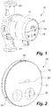
- Fig. 1 shows a perspective view of a pump unit 10 or pump assembly.
- the pump unit 10 comprises a housing 12 or terminal box, which has a front end 14 or display, which may be provided with a number of display units 16, which may provide a simple indication of an operating status of the pump unit.
- the invention also makes it possible to simplify the front end 14 even further, as the necessity of having a display is alleviated, whereby the production cost and thereby the price for the end-consumer may be lowered considerably.
- the front end 14 may be provided without the display units 16.
- the front end 14 is further provided with a light source 18, e.g. in form of a single photo diode or a plurality of photo diodes.
- the pump unit 10 is under operation installed in a pipe system via the pipe flanges 20, 21.
- the housing 12 or terminal box of the pump unit 10 houses an electrical motor and a drive shaft as well as control circuitry of the pump unit 10.
- the electric motor and pump parts are integrated into a common housing.
- the electrical motor and the pump may be arranged in separate housings.
- the control circuitry may control the light source 18 to emit light to display an operating status of the pump unit 10, whereby more detailed information about the operating status may be read out from the pump unit 10, e.g. as binary optical signals.
- the front end 14 of the pump unit 10 may further be provided with one or more buttons, which may be pressed in order to initialise a sequence, where the light source 18 is brought to emit light in order to display the operating status of the pump unit 10.
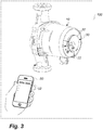
- Fig. 2 shows a perspective view of an electronic converter unit 30 according to the invention.
- the electronic converter unit 30 comprises a housing 31, which houses the electronic circuitry of the electronic converter unit 30.
- the electronic converter unit 30 is adapted to be attached or retrofitted to an external part of the housing 12 of the pump unit 10, preferably adapted to being detachably coupled to the housing 12 of the pump unit 10.
- the electronic converter unit 30 is shown as a circular shaped device, but can also have the shape of a rectangular box. For reasons of handiness, the outer contour of the unit 30 is smaller than the contour of the front end 14.
- the electronic converter unit 10 comprises a photo detector (not shown in Fig. 2 ) for detecting light emitted from the light source 18 of the pump unit 10, and which is arranged on or near a side of the electronic converter unit 30, which when attached to the housing 12 of the pump unit 10 faces towards the housing 12 of the pump unit 10.
- the electronic converter unit 30 may further comprise a number of attachment parts 32, e.g. in form of retractable mechanical fasteners (not shown in Fig. 2 ).
- a front end of the electronic converter unit 30 may further be provided with an indicator or display 34, e.g. for giving an indication of a signal strength of the measured optical signal emitted from the light source 18 of the pump unit 10.
- the display 34 may thus provide a visual feedback to a user providing information about the alignment of the photo detector relative to the light source 18 of the pump unit 10.
- the front end 14 does not contain the light source 18.
- the segments can be turned on or off in a predetermined pattern that can be read and interpreted by the electronic converter unit 30.
- the electronic converter unit 30 is further provided with a communication unit for converting the detected optical signal to an electrical signal, such as infrared or a radio signal, e.g. based on GSM, CDMA, 3G, 4G, , and Bluetooth® 36.
- a communication unit for converting the detected optical signal to an electrical signal, such as infrared or a radio signal, e.g. based on GSM, CDMA, 3G, 4G, , and Bluetooth® 36.
- the front end of the electronic converter unit 30 may be provided with one or more buttons to initialise a sequence, where the electronic converter unit 30 detects optical signals emitted from the light source 18 of the pump unit 10 and converts the optical signals to electrical signals and transmits the electrical signals to an external communication unit, such as a smart phone.
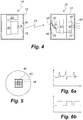
- Fig. 3 shows a system 100 for checking the operating status of a pump unit 10.
- the system 10 comprises the afore-mentioned pump unit 10 and the electronic converter unit 30.
- the electronic converter unit 30 is here shown attached to the front end 14 of the housing 12 of the pump unit 10, such that the photo detector of the electronic converter unit 30 is aligned with the light source 18 of the pump unit 10.
- the electronic converter unit 10 is attached to the front end 14 of the pump unit 10 by use of mechanical fasteners 32, which are connected to sides of the housing 12 of the pump unit 10.
- the electronic converter unit 10 detects the optical signals emitted from the pump unit 10 and converts them to radio signals, which are transmitted to an external communication unit 50 in form of a smart phone having a display 52.
- the smart phone 50 comprises an app, which is installed and running on the smart phone 50.
- the smart phone 50 and app are adapted to receive and process the radio signals sent from the electronic converter unit 30 so as to display the operating status of the pump unit 10 on the display 52 of the smart phone 50.
- the app may further be provided with a function to control the pump unit by setting the operating or drive parameters of the pump unit 10.
- the smart phone 50 may send the control instructions via the electronic converter unit 30.
- Figs. 8a-d show an alternative design for an electronic converter unit 30' for use in the invention, where the electronic converter unit 30' is shaped as an elongated unit.
- the electronic converter unit 30' comprises the same features as the electronic converter unit shown in Fig. 2 . Accordingly, only the differences between the two embodiments are described in the following. Similar to the embodiment of Fig. 2 , the electronic converter unit 30' comprises a housing 31', which houses the electronic circuitry of the electronic converter unit 30'. A front end of the electronic converter unit 30' may further be provided with an indicator or display 34', e.g. for giving an indication of a signal strength of the measured optical signal emitted from the light source 18 of the pump unit 10. The display 34' may thus provide a visual feedback to a user providing information about the alignment of the photo detector relative to the light source 18 of the pump unit 10.
- the electronic converter unit 30' comprises a first mechanical fastener 32', which may advantageously be slidable engaged with a main part of the electronic converter unit and may be extended from a first end of the electronic converter unit 30'.
- the electronic converter unit 30' further comprises a second mechanical fastener 32" at a second end of the unit 30'.
- the distance between the two mechanical fasteners 32', 32" may be varied so that they can mechanical engage sides of the frontend of the pump unit 10.
- the electronic converter unit 30' may further be designed such that the first mechanical fastener 32', when arranged in a closed state, covers and protects an aperture (e.g.
- the mechanical fasteners 32' and 32" may be provided with small rubber pads, placed in the area where they engage with the pump housing. In this way the electronic converter unit 30 is mechanically better fixated to the pump housing and accommodate the shape of the housing.
- the electronic converter unit 30' may further be designed such that a small part 35' of the unit 30' protrudes beyond the housing of the pump unit 10, when the electronic converter unit 30' is arranged on the front end 14 of the pump unit, as shown in Fig. 8d . This may for instance be achieved by letting the second mechanical fastener 32" being spaced slightly from an end face of the unit 30'.
- An antenna may be arranged in the protruding part 35' of the electronic converter unit 30', which may in some instances provide a stronger signal to the handheld communication device.
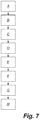
- Fig. 4 shows a schematic drawing of components of the pump unit 10 and the electronic converter unit 30, and Fig. 5 shows a part of the side of the electronic converter unit 30, which faces towards the housing 12 of the pump unit 10, when the electronic converter unit 30 is attached to the pump unit 10.
- the electronic converter unit may for instance correspond to the embodiment of Fig. 2 or Fig. 8 .
- the housing 12 of the pump unit comprises a control circuitry.
- the control circuitry comprises a control unit 24, which controls the emission of light from the light source 18, and which may be instructed to read out the operational status of the pump unit 10 via optical signals 29 or optical data transmitted from the light source 18.
- the light source 18, e.g. in form of one or more photo diodes may be accessible from the housing 12 of the pump unit 10, or it may be arranged behind a window 28. In the preferred embodiment the transmission speed of the diode is 9600 baud.
- the control circuitry further comprises a switch-mode converter or power supply, which comprises a frequency transformer 22.
- the switch-mode converter may for instance be operating in the frequency range of 100 kHz to 200 kHz and may be the source of electrical noise from the pump unit 10.
- the housing 31 of the electronic converter unit 30 also comprises an electronic circuitry.
- the electronic circuitry comprises a first signal detector 40 embodied as a photo detector, e.g. in form of a photo transistor or photo diode, which is connected to a communication unit 41 for detecting and converting the detected optical signal 29.
- the electronic circuitry further comprises a Bluetooth® unit 42, such that the detected signal may be transmitted as a wireless signal transmission 43 to the external communication device 50 via the Bluetooth® protocol.
- Bluetooth® unit 42 comprises an antenna 46, which is used for transmitting a converted signal from the communication unit 41, but also used for receiving airborne signals from outside. Antenna 46 is used as the second signal detector of the electronic converter unit 30.
- the software of the electronic converter unit can be updated by way of antenna 46.
- the electronic converter unit 30 has two input channels, namely a first receiving channel for receiving optical input and a second receiving channel for receiving airborne electrical signals.
- the first receiving channel has an low frequency input range between 1 Hz and 1 MHz
- the second receiving input based on antenna technology has a high frequency input range between 100 MHz and 3 GHz.
- the transmitter or Bluetooth® unit 42 of the electronic converter unit 30 may also use other conventional communication protocols, such as GSM, CDMA, 3G, 4G, or infrared light.
- an electronic amplifier (not shown) increases signal strength. This is relevant for the application of the invention in buildings, where walls separate the electronic converter unit 30 from the handheld device 50. Signal 43 should also reach the handheld device of the service technician from the cellar, even if he is on the third floor.
- An energy supply (not shown), preferably in the form of batteries, are included in the electronic converter unit 30. They supply 40, 41 and 42 with electrical energy. As converter unit 30 in the preferred embodiment is a stand-alone unit supplied by batteries only, energy saving is important.
- the energy supply is shut off, or lowered in the level of supply energy, if detector 40 does not receive an optical signal, or if a transmission-idle-time-limit has been reached, e.g. 30 seconds.
- energy can be supplied by the pump unit itself to the electronic converter unit. This can be achieved by wireless and inductive energy transfer from a coil placed behind the front end 14, said coil then inductively energises a coil placed inside the housing 31 of electronic converter unit 30.
- the photo detector 40 is arranged behind an aperture 45 in the housing 31 of the electronic converter unit 30.
- the aperture may be provided with an optical transparent layer 37, e.g. made of glass, artificial glass, or plastic, and further a conductive layer 38, which is provided with an aperture to allow light to enter and be detected by the photo detector 40.
- the aperture may also comprise a condensing lens or a Fresnel lens in order to ensure that the light from the pump unit 10 reaches the photo detector 40.
- the conductive layer 38 is preferably formed as a mesh structure or an opaque layer with an aperture, such that the conductive layer 38 provides a Faraday cage like mesh structure, which allows light to enter but not electrical noise or interference.
- the Bluetooth® unit 42 is arranged outside the Faraday cage so that it is able to send the converted signal to the external communication device 50.
- the optical transparent layer 37 and the conductive layer 38 may be provided as two separate layers as shown in Fig. 4 , or they may be integrated into a single layer.
- the aperture 45 is shown as being substantially square. However, it may be of any suitable shape, e.g. being round.
- the conductive layer 38 is preferably connected to ground 39.
- the internal part of the housing 31 of the electronic converter device 30 may also be covered by an electric conductive layer, e.g. also in form of a mesh structure.
- the conductive layer or mesh structure 38 may then be grounded to the conductive layer of the housing, which provides a large ground plane.
- the conductive material of the conductive layer and the interior of the housing 31 may for instance be made of metal, such as copper or brass, but any conductive material is in principle applicable.
- the electronic circuitry is preferably also connected to ground.
- the conductive layer 38 and the electronic circuitry may be connected to a common ground or to separate grounds.
- Figs. 6a and 6b illustrate detected signals without and without the mesh structure provided in the aperture 45, respectively.
- the detected signal is very noisy, if the aperture is not provided with an electrical conductive mesh structure.
- the noise may influence the conversion of the detected optical signal 29 to the radio signal transmission 43.
- the electrical noise may be removed and the optical readout may be converted by detector 40, e.g. to clear binary signal as shown in Fig. 6b .
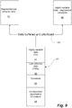
- Fig. 7 illustrates the steps in a method for checking the operating status of the pump unit 10 on the external communication unit 50.
- a first step (A) the pump unit 10 is provided.
- the electronic converter unit 30 for converting an optical data output from the light source of the pump unit to an electrical data signal is arranged on the housing 12 of the pump unit 10 so that the photo detector 40 of the electronic converter unit 30 is aligned with the light source 18 of the pump unit 10.
- a third step (C) the pump unit 10 is brought to a state, where an optical data output is emitted via the light source 18 in order to read out the operating status of the pump unit 10.
- the control unit 24 inside the pump housing 12 sends a data package containing 100 bytes. These 100 bytes are sent in one continuous stream of data, which incorporates relevant information about the pump and its operational status. More precisely the data package contains three types of information namely non-varying or constant information as e.g. pump type or serial number of the pump (pump ID), seldomly varying information and frequently varying information. Frequently varying information is information like pressure in a pipe, liquid flow rate, electrical power or current consumed by the pump motor or rotational speed of the impeller of the pump.
- Figure 9 shows in position number 60 the 100 bytes data package sent from pump diode 18 to the electronic converter unit 30.
- the data package contains the frequently varying data 61, seldomly varying data 62, and two types of constant data 63 and 64.
- the 100 bytes are updated every second and the transmission time from pump to electronic converter unit 30 is 100 milliseconds.
- a fourth step (D) the electronic converter unit 30 detects the optical data output via the photo detector 40.
- a fifth step (E) of Fig.7 the electronic converter unit 30 converts the optical data output to an electrical data signal.
- this is shown with the text "Data buffered and prioritized", pos. no. 65.
- the communication unit 41 of the electronic converter unit 30 re-arranges the data from the 100 bytes data package into a number of telegrams. These telegrams, once finished, are to be transmitted wirelessly from the electronic converter unit to the outside world. More specific a total of four telegrams are formed. One telegram is a so-called "initial telegram", which is sent immediately after the converter unit 30 is activated.
- This telegram informs smart devices, such as smart phones, in the vicinity that the converter unit 30 has arrived on the scene and establishes contact.
- Another telegram type contains information about the Bluetooth® address.
- the last two of the four telegrams contain the operational information from the pump. These two telegrams are shown in Fig.9 with numbers 66 and 67.
- Telegram 66 contains those pump and process parameter values that change frequently, e.g. the electrical current of the motor of the pump, or the rotational speed of the impeller.
- Telegram 67 contains data which are not so frequently updated in the pump.
- the electronic converter unit first takes the highly variable data shown in 61 of Fig.9 and transmits them in telegram 66.
- the electronic converter unit selects portions of the signal from the pump unit and allocates the selected portions either to telegrams to be sent frequently or to telegrams to be sent less frequently.
- a signal transmission 43 to the external communication device 50 takes place.
- the transmission frequency is 2.4 GHz, e.g. via Bluetooth Core Specification 4.0 or 4.1 (also called Bluetooth® smart).
- the transmission mode is the broadcast mode meaning that communication unit 30 sends out the telegrams without establishing pairing or a bidirectional communication link between unit 30 and smart phone 50. Instead, it is a unidirectional communication.
- the telegrams have a length of 31 bytes.
- the electronic unit 30 sends out ten telegrams per second which obviously is more than needed because the pump only updates data every one second.
- a seventh step (G) the external communication device 50 processes the received electrical data signal via an app installed and running on the external communication device 50 and extracts the operating status of the pump unit.
- the external communication device 50 displays the operating status of the pump unit 10 and the display 52 of the external communication device 50.
- the pump unit 10 may further be provided with a receiver for receiving instructions from the electronic converter unit 30, and the electronic converter unit 30 may be provided with a transmitter for transmitting instructions to the pump unit.
- the pump unit may in one embodiment be equipped with a CCD device on the front end 14, and electronic processing devices inside the pump unit would then perform digital image processing.
- a photo detector like detector 40 may be placed in front end 14 instead.
- the electronic converter unit 30 may provide two-way communication and act as an intermediate communication device, which enables the external communication device 50 to receive and transmit information between the external communication device 50 and the pump unit 10 and inter alia to control the pump unit 10. This provides a highly secure system, where a user can only access and control the working parameters of the pump unit 10, if the user both have an electronic converter unit according to the invention and e.g. a smart phone 50 with the correct app installed on the smart phone 50.
- the invention is used in a method for balancing the fluid flow and/or fluid pressure in the pipes of a heating system, such as a system with a plurality of parallel radiators, or parallel heating tubes for floor heating.
- a heating system such as a system with a plurality of parallel radiators, or parallel heating tubes for floor heating.
- the service technician detects an unbalance in the system, and adjusts for example the flow through a radiator by adjusting a valve on the radiator. In this way a radiator, which receives too high flow, experiences a reduced flow due to the adjustment of the valve, and the other radiator(s) receive more flow. Balancing is a way to obtain better heating comfort for the homeowner, and a way to reduce energy consumption.
- the service technician can advantageously use the current invention.
- the service technician When commissioning the heating system in a house, or when later performing maintenance on the system, the service technician places the electronic converter unit 30 on the front end 14 of the pump. He initializes the converter unit 30 to read out the flow and/or pressure through the pump and leaves the site of the pump and goes to the radiators, e.g. on the 3 rd floor of the house. When adjusting the valve of a radiator the adjusted value of flow and/or pressure can be read in the display of the handheld device 50. Based on this information the service technician can perform an easy balancing of the system.
- the handheld device includes an app, which is dedicated to assist the service technician in balancing heating systems.
- the dedicated balancing app instructs the service technician about the steps to be taken when performing balancing and also includes calculation algorithms for calculating optimum heating and energy conditions.
- the service technician informs the app about the number of radiators.
- a second step he closes all radiators, i.e. shuts off the valves, except for one radiator.
- the electronic converter unit 30 then reads the flow and/or pressure through the pump, and informs the handheld device, or more precisely the app of the handheld device.
- the app stores this information.
- the radiator just measured is closed, and another radiator is opened.
- the electronic converter unit makes a new reading and sends this to the app in the handheld device.
- This closing-opening process is repeated until all radiators have been measured, and the most inefficient radiators have been identified by the app.
- the app will then inform the service technician about which radiator is to be adjusted. Instead of sending information about flow or pressure, information about the electrical current of the pump can also be sent.
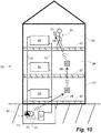
- a house 70 comprises three storeys 93, 94 and 95 and a heating system.
- the heating system comprises a centrifugal pump 72 controlled by a pump controller placed inside housing 73.
- An electronic converter unit 30 is placed on the housing of the pump controller and communicates via optical signals as already described.
- a boiler 75 feeds hot water via pump 72 and pipes 78 and 79 to and from radiators 80.
- the boiler 75 and the centrifugal pump 72 may for instance be installed in a basement 96 of the house 70.
- a service technician 90 reads a radiator balancing app in his handheld device 50, where he can see pump parameter values and be guided into a correct balancing of the radiators.
- Concrete floors 92 between the storeys 93, 94 and 95 of the house are dampening the signal strength of the Bluetooth® signal 85 sent from the electronic unit 30.
- a repeater 86 is placed in storey 93. The repeater reads the signal 85 and relays it to the next repeater 87 at floor 94. This repeater relays the signal as signal 89 to the smart phone 50.
- the repeaters 86 and 87 are identical copies of electronic converter unit 30.
- repeater 86 and 87 can be interchanged freely with unit 30 and be mounted on the pump controller 73.
- Using identical devices for mounting on the pump and for use as a repeater gives large advantages for the manufacturer. Also, the customer and user of such a communication system will not have to learn to products but can stay with one. Once the service technician has switched the repeaters 86, 87 on and placed them in places, where the signals 85 and 88 can be unhindered received, the electronic unit 30 is switched on.
- Figure 11 shows what happens in the software of repeaters 86 and 87.
- the repeater 86 looks for optical input, 111. As there is no optical input because the repeater is not placed on a pump, the repeater realizes that it is a repeater. It starts looking for telegrams. Such telegrams are caught by an antenna inside the repeater 86, more precisely the antenna placed inside Bluetooth® unit 42 (see Fig. 4 ). Once a telegram is detected (112, Fig.11 ) the repeater 86 stores the Bluetooth® address of the sender (the electronic converter unit 30 mounted on the pump), and also stores an identifying number (or sequence number) of the telegram. Pos. 113 shows this.
- the communication line is now established, and a synchronization between repeater 86 and electronic converter unit 30 is made. More precisely the communication between these two units is aligned so that repeater 86 is active exactly at those timings where a new telegram from electronic converter unit 30 is sent. In all other idle periods the repeater 86 is sleeping, see pos.114 and 115 of Fig.11 . This saves battery power in repeater 86.
- Repeater 86 is now ready to receive telegrams to be relayed to other units (116 and 117). It will awaken or listen only once per second.
- the repeater 86 copies the telegram and passes it on to the next level, either repeater 87 or smart phone 50.
- the repeater checks the sequence number of the telegram, which number was allocated to the telegram by the first electronic converter unit 30. The sequence numbers are unique and between 1 and 127 and may be incremented each time a telegram is sent out. If the repeater receives a telegram twice with the same sequence number it will discard the second telegram because this telegram probably is sent by another repeater. It must be avoided that two repeaters are locked together in an eternal messaging.
- the antenna of the repeater 86 is preferably made as a conductor on a printed circuit board.
- the antenna is optimized and designed for functioning as sender when placed on the pump control housing 73. However, when sending as a repeater the signal strength is lower because the repeater is not placed in its optimum transmission environment.
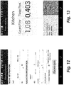
- Fig. 12 shows the balancing app in use on smart phone 50.
- the screen is prompting the service technician for input about heating relevant parameters describing a kitchen room at storey 95. Relevant information is e.g. the size in square meters of the room. Further he is prompted for information about the radiator height. Other parameter values are input in the app on screens not shown.
- the app is ready to calculate and assist the service technician in the balancing process. Based on the input values, the needed emission power or heat for the heating element is thus calculated by the app, which in turn makes it possible to calculate a design flow, which is needed in order to achieve the required emission of heat from the heating element, as the heating fluid passes through the heating element. As already described all but one radiator is closed when doing a balancing.
- Pump 72 is then started.
- the pump controller placed in housing 73 sends via diode 18 a data package to electronic converter unit 30.
- Electronic converter unit 30 converts the optical signal to a Bluetooth® signal, which is received by repeater 86 ( Fig.10 ) via its antenna.
- the signal is relayed to repeater 87 and then to smart phone 50.
- the current flow through the pump is displayed in the app and shown in the left hand side of Fig.13 and compared to the calculated target or optimum flow. During the balancing operation the current flow, i.e. the actual flow, through the kitchen line is thus shown on the screen.
- the operator Once the current flow is equal to or close to the target flow the operator must press the "Done” button, and can via "Next” continue to balance the radiator in the next room.
- Each of the balancing valves (not shown) on the radiators are adjusted in sequence so as to meet the design flow for each heating element by tracking the current flow rate in the app as the corresponding balancing valve is adjusted.
- a report is generated by the app, and the report can be accessed from the app or sent by email to relevant recipients.
- the invention has been described with reference to advantageous embodiments. Thus, instead of balancing the invention can also be used solely for logging of data from the pump. Further the invention is not limited to heating systems with radiators but can as well be used in floor heating systems. The scope of the invention is thus not limited to the illustrated embodiments, and alterations and modifications can be carried out without deviating from the scope of the invention, which is defined by the following claims.
- the invention has for instance been described with reference to embodiments based on an optical readout of the operating status of the pump unit. However, it is recognised that the communication may also be based on other proximity sensor systems.
- the communication between the pump unit and the electronic converter unit may for instance be based on RFID or NFC technology.
- the communication between the pump unit and the electronic converter unit may also be based on sound signals or other suitable signals.
- Reference Numerals 10 Pump unit 12 Housing / terminal box 14 Front end / display 16 Display units 18 Light source / diode 20, 21 Pipe flanges 22 Frequency transformer 24 Control unit 28 Window 29 Light / Optical signal / optical data 30 Electronic converter unit 31 Housing 32 Fasteners 34 Display / Indicator 36 Bluetooth 37 Optical transparent layer 38 Mesh structure / conductive layer 39 Ground 40 Photo detector 41 Communication unit 42 Bluetooth converter / transmitting means 43 Radio signal transmission 45 Apertu re 46 Second signal detector / antenna 47 Anten na 50 External communication device / smart phone 52 Display 60-67 Data packages, telegrams, and data contents 70 house 72 Centrifugal pump 73 Pump housing 75 Boiler 78, 79 Pipes 80 Radiators 85, 88, 89 Signals 86, 87 Electronic converter unit operating as repeater 90 Service technician 92 Concrete floors 93-95 Storeys 96 Basement 100 System for checking the operating
Landscapes
- Engineering & Computer Science (AREA)
- Mechanical Engineering (AREA)
- General Engineering & Computer Science (AREA)
- Physics & Mathematics (AREA)
- Thermal Sciences (AREA)
- Chemical & Material Sciences (AREA)
- Combustion & Propulsion (AREA)
- Computer Networks & Wireless Communication (AREA)
- Signal Processing (AREA)
- Structures Of Non-Positive Displacement Pumps (AREA)
- Control Of Non-Positive-Displacement Pumps (AREA)
- Compressor (AREA)
- Electromagnetism (AREA)
- General Physics & Mathematics (AREA)
- Control Of Positive-Displacement Pumps (AREA)
- Steam Or Hot-Water Central Heating Systems (AREA)
Claims (15)
- Elektronische Wandlereinheit (30, 86, 87), die extern zu einer Pumpeneinheit (10) angeordnet werden soll, wobei die Pumpeinheit (10) ein Gehäuse (12) einschießt, das eine Signalquelle (16, 18) zum Emittieren eines Signals umfasst, wobei die elektronische Wandlereinheit (30, 86, 87) umfasst:- einen ersten Signaldetektor (40) zum Detektieren des Signals, das von der Signalquelle (18) der Pumpeneinheit (10) emittiert wird,- eine Wandlereinheit (41) zum Wandeln des detektierten Signals in ein elektrisches Signal, und- Übertragungsmittel (42) zum Übertragen des elektrischen Signals an eine externe Kommunikationseinheit (50), dadurch gekennzeichnet, dass die elektronische Wandlereinheit (30, 86, 87) weiter konfiguriert ist, um in einem Signalwandlermodus (30) unter Verwendung des ersten Signaldetektors (40) und eines Signal-Repeater-Modus (86, 87) unter Verwendung eines zweiten Signaldetektors betrieben zu werden, und dass die elektronische Wandlereinheit (30, 86, 87) konfiguriert ist, um sich selbst automatisch in den Signalwandlermodus zu setzen, falls der erste Signaldetektor (40) ein Signal von der Signalquelle (18) der Pumpeneinheit (10) detektiert, und in den Signal-Repeater-Modus, falls der erste Signaldetektor ein Signal von der Signalquelle nicht detektiert.
- Elektronische Wandlereinheit nach Anspruch 1, wobei- die elektronische Wandlereinheit (30, 86, 87) in einem Signalwandlermodus das Signal von der Signalquelle (18) der Pumpeneinheit (10) empfängt, und wobei- die elektronische Wandlereinheit (30, 86, 87) in dem Signal-Repeater-Modus konfiguriert ist, um elektrische Signale von einer identischen Wandlereinheit (30, 86, 87) zu empfangen, und das elektrische Signal an eine weitere identische Wandlereinheit (30, 86, 87) oder die externe Kommunikationseinheit (50) weiterleitet.
- Elektronische Wandlereinheit nach einem der vorstehenden Ansprüche, wobei der elektronische Wandler (30, 86, 87) konfiguriert ist, um Telegramme in einem Sendemodus zu senden, vorzugsweise als unidirektionale Kommunikation.
- Elektronische Wandlereinheit nach einem der vorstehenden Ansprüche, wobei die elektronische Wandlereinheit (30, 86, 87) in einem Repeater-Modus konfiguriert ist, um mit einer anderen identischen elektronischen Wandlereinheit (30, 86, 87) synchronisiert zu werden.
- Elektronische Wandlereinheit nach einem der vorstehenden Ansprüche, wobei die elektronische Wandlereinheit (30, 86, 87) konfiguriert ist, um Telegramme zu empfangen und zu übertragen, einschließend Datenpakete, umfassend mindestens erste Datenpakete (66) und zweite Datenpakete (67), und wobei die ersten Datenpakete (66) nach einer ersten Wiederholungsrate übertragen werden und die zweiten Datenpakete (67) nach einer zweiten Wiederholungsrate gesendet werden.
- Elektronische Wandereinheit nach Anspruch 5, wobei die ersten Datenpakete (66) zeitvariable Daten über Pumpenbetrieb (61) umfassen, wie gemessene oder berechnete tatsächliche Flussrate, Druck, elektrischer Strom, elektrische Leistung und/oder Rotationsgeschwindigkeit eines Impellers, und die zweiten Pakete (67) statische Daten (63, 64), wie Pumpenmodelltyp, Seriennummer und dergleichen umfassen, und wobei die erste Wiederholungsrate höher als die zweite Wiederholungsrate ist, z. B. wobei die erste Wiederholungsrate mindestens dreimal größer und vorzugsweise mindestens fünfmal größer als die zweite Widerholungsrate ist.
- Elektronische Wandlereinheit (30, 86, 87) nach einem der vorstehenden Ansprüche, wobei die elektronische Wandlereinheit (30, 86, 87) angepasst ist, um abnehmbar mit der Pumpeneinheit (10) gekoppelt zu werden.
- Elektronische Wandlereinheit (30, 86, 87) nach einem der Ansprüche 1 - 7, wobei die Signalquelle (16, 18) eine Lichtquelle ist, und wobei der erste Signaldetektor (40) ein Fotodetektor zum Messen des Lichts ist, das von der Lichtquelle der Pumpe emittiert wird, und wobei die Wandlereinheit (41) angepasst ist zum Wandeln optischer Signale in elektrische Signale, und wobei der zweite Signaldetektor eine Antenne (46) ist.
- Elektronische Wandlereinheit (30, 86, 87) nach einem der Ansprüche 1 - 7, wobei die elektronische Wandlereinheit (30, 86, 87) umfasst:- einen RFID- oder Nah-Feld-Kommunikationsempfänger,- eine Wandlereinheit zum Wandeln eines RFID- oder NFC-Signals in elektrische Signale, und- Übertragungsmittel zum Übertragen des elektrischen Signals an eine externe Kommunikationseinheit.
- Elektronische Wandlereinheit (30, 86, 87) nach einem der vorstehenden Ansprüche, wobei die Wandlereinheit (30, 86, 87) angepasst ist, um drahtlos die elektrischen Signale als Infrarot- oder als ein Funksignal, wie GSM, CDMA, 3G, 4G und Bluetooth® zu übertragen.
- Bausatz von Teilen, umfassend:- eine Pumpeneinheit (10),- eine erste elektronische Wandlereinheit (30) nach einem der Ansprüche 1 - 10, die konfigurierbar ist, um in einem Wandlermodus betrieben zu werden, und- eine zweite elektronische Wandlereinheit (86, 87) nach einem der Ansprüche 1 - 10, die konfigurierbar ist, um in einem Repeater-Modus betrieben zu werden.
- System (100) zum Prüfen des Betriebsstatus einer Pumpeneinheit, wobei das System umfasst:- eine Pumpeneinheit (10),- eine externe Kommunikationseinheit (50),- eine erste elektronische Wandlereinheit (30) nach einem der Ansprüche 1 - 10, die in einem Wandlermodus betrieben wird, und- mindestens eine zweite elektronische Wandlereinheit (86, 87) nach einem der Ansprüche 1 - 10, die in einem Repeater-Modus betrieben wird.
- Verfahren zur Kommunikation zwischen einer Pumpeneinheit (10) und einer externen Kommunikationseinheit (50), wie ein Smartphone, dadurch gekennzeichnet, dass das Verfahren die folgenden Schritte umfasst:- Anordnen einer ersten elektronischen Wandlereinheit (30), die zu der Pumpeneinheit extern ist, wobei sich die elektronische Wandlereinheit automatisch selbst setzt, um in einem Signalwandlermodus zu betrieben zu werden,- Positionieren eines oder mehrerer elektronischer Wandler (86, 87) zwischen der ersten elektronischen Wandlereinheit und der externen Kommunikationsvorrichtung (50), wobei die zweite elektronische Wandlereinheit sich automatisch selbst in einen Signal-Repeater-Modus setzt, sodass- die erste elektronische Wandlereinheit Signale von der Pumpeneinheit (10) detektiert und sie in digitale Telegramme oder Datenpakete (66, 67) wandelt, die als elektronische Signale (85) übertragen werden, und sodass die zweite elektronische Wandlereinheit oder -einheiten die digitalen Telegramme oder Datenpakete (66, 67) an die externe Kommunikationseinheit (50) weiterleitet (88, 89).
- Verfahren nach Anspruch 13, wobei die elektronische Wandlereinheit (30, 86, 87), nachdem sie aktiviert wurde, eine erste Signaldetektor- (40) -eingabe auf der elektronischen Wandlereinheit inspiziert und, falls die erste Signaldetektoreingabe untätig ist, dann in den Signal-Repeater-Modus schaltet, um digitale Telegramme oder Datenpakete auf der zweiten Signaldetektor- (46) - eingabe zu empfangen.
- Verfahren nach den Ansprüchen 13 oder 14, verwendet zum Ausgleichen von Heizelementen (80) in einem Heizsystem.
Applications Claiming Priority (3)
| Application Number | Priority Date | Filing Date | Title |
|---|---|---|---|
| PCT/EP2014/076416 WO2016086986A1 (en) | 2014-12-03 | 2014-12-03 | An electronic converter unit for retrofitting to an external part of a housing of a pump unit |
| PCT/EP2015/054980 WO2016087056A1 (en) | 2014-12-03 | 2015-03-10 | An electronic converter unit for retrofitting to an external part of a housing of a pump unit |
| PCT/EP2015/078547 WO2016087595A1 (en) | 2014-12-03 | 2015-12-03 | An electronic converter unit for a pump and a method for communicating with the electronic converter unit |
Publications (2)
| Publication Number | Publication Date |
|---|---|
| EP3227559A1 EP3227559A1 (de) | 2017-10-11 |
| EP3227559B1 true EP3227559B1 (de) | 2021-05-19 |
Family
ID=52103109
Family Applications (3)
| Application Number | Title | Priority Date | Filing Date |
|---|---|---|---|
| EP15708554.9A Active EP3227614B1 (de) | 2014-12-03 | 2015-03-10 | Verfahren und system zum ausgleichen eines heizsystems |
| EP15711445.5A Active EP3227558B1 (de) | 2014-12-03 | 2015-03-10 | Elektronische wandlereinheit zum nachrüsten eines aussenteils eines gehäuses einer pumpeinheit |
| EP15804512.0A Active EP3227559B1 (de) | 2014-12-03 | 2015-12-03 | Elektronische wandlereinheit für eine pumpe und verfahren zur kommunikation mit der elektronischen wandlereinheit |
Family Applications Before (2)
| Application Number | Title | Priority Date | Filing Date |
|---|---|---|---|
| EP15708554.9A Active EP3227614B1 (de) | 2014-12-03 | 2015-03-10 | Verfahren und system zum ausgleichen eines heizsystems |
| EP15711445.5A Active EP3227558B1 (de) | 2014-12-03 | 2015-03-10 | Elektronische wandlereinheit zum nachrüsten eines aussenteils eines gehäuses einer pumpeinheit |
Country Status (4)
| Country | Link |
|---|---|
| US (3) | US11365891B2 (de) |
| EP (3) | EP3227614B1 (de) |
| CN (3) | CN107003014B (de) |
| WO (4) | WO2016086986A1 (de) |
Families Citing this family (27)
| Publication number | Priority date | Publication date | Assignee | Title |
|---|---|---|---|---|
| WO2016086986A1 (en) * | 2014-12-03 | 2016-06-09 | Grundfos Holding A/S | An electronic converter unit for retrofitting to an external part of a housing of a pump unit |
| US20170170979A1 (en) | 2015-12-15 | 2017-06-15 | Pentair Flow Technologies, Llc | Systems and Methods for Wireless Control and Monitoring of Residential Devices |
| US10711788B2 (en) | 2015-12-17 | 2020-07-14 | Wayne/Scott Fetzer Company | Integrated sump pump controller with status notifications |
| CN109074056B (zh) * | 2016-04-15 | 2022-03-18 | 贝利莫控股公司 | 用于在hvac系统的设备上进行紧固的控制适配器 |
| WO2018106726A1 (en) | 2016-12-06 | 2018-06-14 | Pentair Flow Technologies, Llc | Connected pump system controller and method of use |
| EP3244641A1 (de) * | 2016-12-20 | 2017-11-15 | Grundfos Holding A/S | Autorisieren einer datenkommunikation mit einem elektronisch gesteuerten pumpenaggregat |
| USD893552S1 (en) | 2017-06-21 | 2020-08-18 | Wayne/Scott Fetzer Company | Pump components |
| EP3682114A4 (de) * | 2017-09-13 | 2021-05-26 | Nymet Innovations Pty Ltd | Pumpensteuerungsvorrichtungen, anwendungen und systeme |
| DE102017123560B4 (de) * | 2017-10-10 | 2024-09-12 | Eut Edelstahl Umformtechnik Gmbh | Selbstregulierende Einstellvorrichtung für ein Durchflussregelventil |
| CN108087963B (zh) * | 2017-12-20 | 2020-03-10 | 大连海事大学 | 一种基于体感温度的智能楼宇控制系统 |
| USD890211S1 (en) | 2018-01-11 | 2020-07-14 | Wayne/Scott Fetzer Company | Pump components |
| DE102018200645B3 (de) | 2018-01-16 | 2019-05-09 | Magna Powertrain Bad Homburg GmbH | Fluidische Maschine |
| IT201800003117A1 (it) * | 2018-02-28 | 2019-08-28 | Dab Pumps Spa | Assemblato di elettropompa centrifuga con dispositivo migliorato di interfaccia utente |
| EP3546840A3 (de) * | 2018-03-30 | 2020-05-27 | Bosch Termoteknik Isitma ve Klima Sanayi Ticaret Anonim Sirketi | Warmwasserbereiter |
| CN108915980B (zh) * | 2018-06-05 | 2020-01-10 | 河北工程大学 | 河床式取水构筑物 |
| SE543008C2 (sv) * | 2018-11-22 | 2020-09-22 | Stockholm Exergi Ab | Förfarande och system för balansering av massflöde under produktionsstörning eller -brist i ett fjärrvärmenät |
| SE543709C2 (en) * | 2019-04-17 | 2021-06-22 | Pandrol Ab | Mobile energy supply unit for hand-held hydraulic tools and method for operating a hand-held hydraulic tool |
| EP3734396B1 (de) | 2019-04-29 | 2021-09-08 | Grundfos Holding A/S | Steuerungssystem und verfahren zur steuerung eines fluidverteilungssystems |
| CN110332604A (zh) * | 2019-06-17 | 2019-10-15 | 合肥瑞纳节能工程有限公司 | 一种换热站一次侧水流量的调节方法及系统 |
| EP4004446B1 (de) * | 2019-07-22 | 2023-06-21 | Belimo Holding AG | Verfahren und system zum ausgleichen eines hydronischen netzwerks |
| IT201900012846A1 (it) * | 2019-07-25 | 2021-01-25 | Dab Pumps Spa | Dispositivo perfezionato di controllo e gestione di una o più elettropompe |
| CN112032800B (zh) * | 2020-09-09 | 2021-07-06 | 山东鲁航智能科技有限公司 | 一种智能化管网平衡系统及其调控方法 |
| US11935393B2 (en) * | 2020-11-10 | 2024-03-19 | Grace Technologies, Inc. | Smart wireless communication device |
| AU2022226959B2 (en) * | 2021-02-25 | 2025-11-06 | Zodiac Pool Systems Llc | User interface for pumps for swimming pools and spas |
| WO2023007332A1 (en) * | 2021-07-29 | 2023-02-02 | Ariston S.P.A. | Method for hydraulic balancing of a space heating system |
| EP4163565B1 (de) | 2021-10-05 | 2024-07-31 | Carrier Corporation | Nahfeldkommunikationsvorrichtung zur anbringung an einem gehäuse einer hlk-ausseneinheit |
| DE102022209157A1 (de) * | 2022-09-02 | 2024-03-07 | Robert Bosch Gesellschaft mit beschränkter Haftung | Drahtlose Kontrollvorrichtung für Heizsysteme und/oder Smarthome-Systeme |
Family Cites Families (43)
| Publication number | Priority date | Publication date | Assignee | Title |
|---|---|---|---|---|
| FR2547396B1 (fr) * | 1983-06-09 | 1985-07-12 | Sdecc | Procede d'equilibrage d'une installation de chauffage central de type bitube et installation pour la mise en oeuvre de ce procede |
| GB2149176B (en) | 1983-10-26 | 1988-07-13 | Stc Plc | Addressing liquid crystal displays |
| DE3529257C2 (de) * | 1985-08-16 | 1996-09-26 | Forschungsgesellschaft Heizung | Verfahren und Anordnung zur Ermittlung der Wärmeabgabe von Heizflächen einer Heizungsanlage |
| DE3529256C2 (de) * | 1985-08-16 | 1994-06-16 | Forschungsgesellschaft Heizung | Verfahren und Anordnung zum hydraulischen Abgleichen eines Heizkreislaufs |
| DE3844960C2 (de) * | 1988-08-19 | 1997-11-20 | Wilo Gmbh | Elektrisch angetriebenes Pumpenaggregat und seine Verwendung |
| FR2711775B1 (fr) * | 1993-10-21 | 1996-02-02 | Tour Andersson Sa | Dispositif de contrôle et de mesure énergétique. |
| FR2746168B1 (fr) | 1996-03-14 | 1998-04-30 | Procede d'equilibrage d'un reseau de distribution de fluide non compressible a deux tubes, a plusieurs branches ou colonnes derivees | |
| DE10018866A1 (de) * | 2000-04-14 | 2001-10-25 | Grundfos As | Pumpenaggregat |
| WO2001095646A1 (en) | 2000-06-07 | 2001-12-13 | Telemics, Inc. | Method and system for monitoring and controlling working components |
| GB2371634B (en) * | 2001-01-30 | 2005-05-25 | Aqualisa Products Ltd | Water mixing valve apparatus |
| US7009530B2 (en) * | 2001-09-13 | 2006-03-07 | M&Fc Holding, Llc | Modular wireless fixed network for wide-area metering data collection and meter module apparatus |
| DE50114450D1 (de) | 2001-12-22 | 2008-12-11 | Grundfos As | Elektrische Einrichtung zur Datenübertragung |
| DE20206267U1 (de) * | 2002-04-20 | 2003-08-28 | Leybold Vakuum GmbH, 50968 Köln | Vakuumpumpe |
| US6666042B1 (en) * | 2002-07-01 | 2003-12-23 | American Standard International Inc. | Sequencing of variable primary flow chiller system |
| US7563248B2 (en) * | 2005-03-17 | 2009-07-21 | Smisson-Cartledge Biomedical Llc | Infusion fluid heat exchanger and cartridge |
| DE102007017445C5 (de) | 2007-04-02 | 2015-08-27 | Alfred Kärcher Gmbh & Co. Kg | Flüssigkeitspumpe |
| US9730078B2 (en) * | 2007-08-31 | 2017-08-08 | Fisher-Rosemount Systems, Inc. | Configuring and optimizing a wireless mesh network |
| DE102008003315A1 (de) | 2008-01-07 | 2009-07-09 | Viessmann Werke Gmbh & Co Kg | Heizungsanlage und Verfahren zum Betrieb einer Heizungsanlage |
| US8024161B2 (en) | 2008-08-19 | 2011-09-20 | Honeywell International Inc. | Method and system for model-based multivariable balancing for distributed hydronic networks |
| CN101344274B (zh) * | 2008-08-25 | 2011-06-15 | 北京硕人时代科技有限公司 | 锅炉供热气候补偿系统及其实现方法 |
| CN101509677A (zh) * | 2009-03-31 | 2009-08-19 | 王彦国 | 高层建筑直接供暖系统的水循环系统及其控制方法 |
| CN201522025U (zh) * | 2009-08-14 | 2010-07-07 | 乔养正 | 太阳能供暖供热水设备 |
| FR2958475B1 (fr) * | 2010-03-30 | 2012-09-28 | Sophia Conseil | Systeme de controle. |
| KR101343863B1 (ko) * | 2011-04-15 | 2013-12-20 | 한국건설기술연구원 | 변유량 난방제어장치 및 그 방법 |
| US9695827B2 (en) * | 2011-06-22 | 2017-07-04 | Toyota Jidosha Kabushiki Kaisha | Control device for electric water pump |
| CH705143A1 (de) * | 2011-06-30 | 2012-12-31 | Belimo Holding Ag | Verfahren und Vorrichtungen zum Abgleichen einer Gruppe von Verbrauchern in einem Fluidtransportsystem. |
| US20130051024A1 (en) * | 2011-08-31 | 2013-02-28 | Moshe Amit | Optical Transmitter Assembly, Optical Transceivers Including the Same, and Methods of Making and Using Such Optical Transmitter Assemblies and Optical Transceivers |
| EP2573403B1 (de) * | 2011-09-20 | 2017-12-06 | Grundfos Holding A/S | Pumpe |
| EP3496245B1 (de) | 2012-02-08 | 2024-09-18 | Grundfos Holding A/S | Elektromotor |
| WO2013130799A1 (en) * | 2012-02-28 | 2013-09-06 | Emerson Climate Technologies, Inc. | Hvac system remote monitoring and diagnosis |
| US9330560B2 (en) * | 2012-05-02 | 2016-05-03 | Flowserve Management Company | Reconfigurable equipment monitoring systems and methods |
| EP2696175B1 (de) | 2012-08-07 | 2021-09-15 | Grundfos Holding A/S | Verfahren zum Erfassen der Durchflussmenge einer Kreiselpumpe |
| CN202904852U (zh) * | 2012-09-27 | 2013-04-24 | 无锡豪居智能科技有限公司 | 基于物联网智能信息化的学习、转换及中继无线控制装置 |
| AT513733A1 (de) | 2012-10-30 | 2014-06-15 | Vaillant Group Austria Gmbh | Verfahren zum hydraulischen Abgleich eines Heizungssystems |
| CH707402A2 (de) * | 2012-12-18 | 2014-06-30 | Belimo Holding Ag | Verfahren und Vorrichtung zum Abgleichen einer Gruppe von Verbrauchern in einem Fluidtransportsystem. |
| US8895429B2 (en) * | 2013-03-05 | 2014-11-25 | Eastman Kodak Company | Micro-channel structure with variable depths |
| EP2778423B1 (de) * | 2013-03-11 | 2018-02-28 | Grundfos Holding A/S | Kreiselpumpenaggregat |
| US20140314062A1 (en) * | 2013-04-19 | 2014-10-23 | Dennis Loebs | Aquatic-Based Automation Systems |
| CN103778748B (zh) * | 2013-07-08 | 2016-04-13 | 高幼苏 | 一种火场火情实时检测方法及系统 |
| KR20150030098A (ko) * | 2013-09-11 | 2015-03-19 | 한국전자통신연구원 | 착탈형 광 트랜시버 |
| CA2922754C (en) * | 2013-10-16 | 2018-03-13 | F. Hoffmann-La Roche Ag | Communication interface clip for a handheld medical device |
| US9841644B2 (en) * | 2014-05-06 | 2017-12-12 | Apple Inc. | Electrostatic discharge protection structures for liquid crystal displays |
| WO2016086986A1 (en) * | 2014-12-03 | 2016-06-09 | Grundfos Holding A/S | An electronic converter unit for retrofitting to an external part of a housing of a pump unit |
-
2014
- 2014-12-03 WO PCT/EP2014/076416 patent/WO2016086986A1/en not_active Ceased
-
2015
- 2015-03-10 EP EP15708554.9A patent/EP3227614B1/de active Active
- 2015-03-10 US US15/532,278 patent/US11365891B2/en active Active
- 2015-03-10 CN CN201580066145.4A patent/CN107003014B/zh active Active
- 2015-03-10 EP EP15711445.5A patent/EP3227558B1/de active Active
- 2015-03-10 WO PCT/EP2015/054983 patent/WO2016087057A1/en not_active Ceased
- 2015-03-10 WO PCT/EP2015/054980 patent/WO2016087056A1/en not_active Ceased
- 2015-03-10 CN CN201580066149.2A patent/CN107002693A/zh active Pending
- 2015-03-10 US US15/532,238 patent/US10697649B2/en not_active Expired - Fee Related
- 2015-12-03 US US15/532,294 patent/US10132508B2/en active Active
- 2015-12-03 EP EP15804512.0A patent/EP3227559B1/de active Active
- 2015-12-03 WO PCT/EP2015/078547 patent/WO2016087595A1/en not_active Ceased
- 2015-12-03 CN CN201580064784.7A patent/CN107002691B/zh active Active
Non-Patent Citations (1)
| Title |
|---|
| None * |
Also Published As
| Publication number | Publication date |
|---|---|
| US20170328579A1 (en) | 2017-11-16 |
| EP3227558A1 (de) | 2017-10-11 |
| EP3227614C0 (de) | 2024-09-11 |
| CN107003014B (zh) | 2020-07-24 |
| EP3227614A1 (de) | 2017-10-11 |
| CN107003014A (zh) | 2017-08-01 |
| WO2016087057A1 (en) | 2016-06-09 |
| CN107002693A (zh) | 2017-08-01 |
| WO2016086986A1 (en) | 2016-06-09 |
| US20170328367A1 (en) | 2017-11-16 |
| CN107002691A (zh) | 2017-08-01 |
| EP3227558B1 (de) | 2022-05-04 |
| US20170272844A1 (en) | 2017-09-21 |
| US11365891B2 (en) | 2022-06-21 |
| US10697649B2 (en) | 2020-06-30 |
| EP3227559A1 (de) | 2017-10-11 |
| CN107002691B (zh) | 2021-04-16 |
| US10132508B2 (en) | 2018-11-20 |
| EP3227614B1 (de) | 2024-09-11 |
| WO2016087056A1 (en) | 2016-06-09 |
| WO2016087595A1 (en) | 2016-06-09 |
Similar Documents
| Publication | Publication Date | Title |
|---|---|---|
| EP3227559B1 (de) | Elektronische wandlereinheit für eine pumpe und verfahren zur kommunikation mit der elektronischen wandlereinheit | |
| US8393550B2 (en) | Thermostat assembly with removable communication module and method | |
| CN102705965A (zh) | 一种采用移动智能终端控制的空调器 | |
| KR101172002B1 (ko) | 스마트폰과 센서를 이용한 인공지능 디지털기기 제어시스템 | |
| JP5182043B2 (ja) | 電力監視装置 | |
| JP2014195227A (ja) | 電気機器の遠隔操作システム | |
| CA2715200A1 (en) | High power radio device communication parameter configuration and methods using limited configuration power | |
| CN105909541A (zh) | 智能无线遥控电风扇 | |
| CN104377517A (zh) | 一种基于大功率红外发射管的家电智能插座 | |
| KR101377065B1 (ko) | 모바일 기기를 이용한 홈오토메이션 시스템 | |
| US20120293337A1 (en) | Energy Monitoring Apparatus | |
| KR102317654B1 (ko) | 블럭형 모듈 적층 구조를 갖는 IoT 커스터마이징 디바이스 | |
| KR102201748B1 (ko) | 사물인터넷 기반의 통합 리모콘 시스템 | |
| KR20120002306A (ko) | 리모콘을 위한 비접촉 충전 장치를 갖춘 비데 | |
| CN202758083U (zh) | 传感器系统以及包含传感器的照明设备 | |
| CN205375031U (zh) | 一种基于摄像机的智能家居控制装置 | |
| JP2012109747A (ja) | 無線装置 | |
| EP2525191B1 (de) | Energieüberwachungsvorrichtung | |
| KR20120065168A (ko) | 이동형 무선기기를 이용한 홈네트워크 제어 시스템 | |
| JP2009021714A (ja) | リモコン動作確認システム | |
| JP4385544B2 (ja) | ガス検知装置 | |
| KR101611265B1 (ko) | 에어컨 수리용 가동 제어 장치 | |
| JP6014212B2 (ja) | 防災又は防犯システム用の携帯式通信設定装置 | |
| JP5819603B2 (ja) | 防災又は防犯システム用の携帯式通信設定装置 | |
| CN203386337U (zh) | 智能家居自适应传感器选配识别器 |
Legal Events
| Date | Code | Title | Description |
|---|---|---|---|
| STAA | Information on the status of an ep patent application or granted ep patent |
Free format text: STATUS: THE INTERNATIONAL PUBLICATION HAS BEEN MADE |
|
| PUAI | Public reference made under article 153(3) epc to a published international application that has entered the european phase |
Free format text: ORIGINAL CODE: 0009012 |
|
| STAA | Information on the status of an ep patent application or granted ep patent |
Free format text: STATUS: REQUEST FOR EXAMINATION WAS MADE |
|
| 17P | Request for examination filed |
Effective date: 20170626 |
|
| AK | Designated contracting states |
Kind code of ref document: A1 Designated state(s): AL AT BE BG CH CY CZ DE DK EE ES FI FR GB GR HR HU IE IS IT LI LT LU LV MC MK MT NL NO PL PT RO RS SE SI SK SM TR |
|
| AX | Request for extension of the european patent |
Extension state: BA ME |
|
| DAV | Request for validation of the european patent (deleted) | ||
| DAX | Request for extension of the european patent (deleted) | ||
| STAA | Information on the status of an ep patent application or granted ep patent |
Free format text: STATUS: EXAMINATION IS IN PROGRESS |
|
| 17Q | First examination report despatched |
Effective date: 20191210 |
|
| GRAP | Despatch of communication of intention to grant a patent |
Free format text: ORIGINAL CODE: EPIDOSNIGR1 |
|
| STAA | Information on the status of an ep patent application or granted ep patent |
Free format text: STATUS: GRANT OF PATENT IS INTENDED |
|
| INTG | Intention to grant announced |
Effective date: 20201208 |
|
| GRAS | Grant fee paid |
Free format text: ORIGINAL CODE: EPIDOSNIGR3 |
|
| GRAA | (expected) grant |
Free format text: ORIGINAL CODE: 0009210 |
|
| STAA | Information on the status of an ep patent application or granted ep patent |
Free format text: STATUS: THE PATENT HAS BEEN GRANTED |
|
| AK | Designated contracting states |
Kind code of ref document: B1 Designated state(s): AL AT BE BG CH CY CZ DE DK EE ES FI FR GB GR HR HU IE IS IT LI LT LU LV MC MK MT NL NO PL PT RO RS SE SI SK SM TR |
|
| REG | Reference to a national code |
Ref country code: GB Ref legal event code: FG4D |
|
| REG | Reference to a national code |
Ref country code: CH Ref legal event code: EP |
|
| REG | Reference to a national code |
Ref country code: DE Ref legal event code: R096 Ref document number: 602015069494 Country of ref document: DE |
|
| REG | Reference to a national code |
Ref country code: AT Ref legal event code: REF Ref document number: 1394239 Country of ref document: AT Kind code of ref document: T Effective date: 20210615 |
|
| REG | Reference to a national code |
Ref country code: IE Ref legal event code: FG4D |
|
| REG | Reference to a national code |
Ref country code: LT Ref legal event code: MG9D |
|
| REG | Reference to a national code |
Ref country code: NL Ref legal event code: MP Effective date: 20210519 |
|
| PG25 | Lapsed in a contracting state [announced via postgrant information from national office to epo] |
Ref country code: LT Free format text: LAPSE BECAUSE OF FAILURE TO SUBMIT A TRANSLATION OF THE DESCRIPTION OR TO PAY THE FEE WITHIN THE PRESCRIBED TIME-LIMIT Effective date: 20210519 Ref country code: FI Free format text: LAPSE BECAUSE OF FAILURE TO SUBMIT A TRANSLATION OF THE DESCRIPTION OR TO PAY THE FEE WITHIN THE PRESCRIBED TIME-LIMIT Effective date: 20210519 Ref country code: BG Free format text: LAPSE BECAUSE OF FAILURE TO SUBMIT A TRANSLATION OF THE DESCRIPTION OR TO PAY THE FEE WITHIN THE PRESCRIBED TIME-LIMIT Effective date: 20210819 Ref country code: HR Free format text: LAPSE BECAUSE OF FAILURE TO SUBMIT A TRANSLATION OF THE DESCRIPTION OR TO PAY THE FEE WITHIN THE PRESCRIBED TIME-LIMIT Effective date: 20210519 |
|
| PG25 | Lapsed in a contracting state [announced via postgrant information from national office to epo] |
Ref country code: SE Free format text: LAPSE BECAUSE OF FAILURE TO SUBMIT A TRANSLATION OF THE DESCRIPTION OR TO PAY THE FEE WITHIN THE PRESCRIBED TIME-LIMIT Effective date: 20210519 Ref country code: RS Free format text: LAPSE BECAUSE OF FAILURE TO SUBMIT A TRANSLATION OF THE DESCRIPTION OR TO PAY THE FEE WITHIN THE PRESCRIBED TIME-LIMIT Effective date: 20210519 Ref country code: NO Free format text: LAPSE BECAUSE OF FAILURE TO SUBMIT A TRANSLATION OF THE DESCRIPTION OR TO PAY THE FEE WITHIN THE PRESCRIBED TIME-LIMIT Effective date: 20210819 Ref country code: PL Free format text: LAPSE BECAUSE OF FAILURE TO SUBMIT A TRANSLATION OF THE DESCRIPTION OR TO PAY THE FEE WITHIN THE PRESCRIBED TIME-LIMIT Effective date: 20210519 Ref country code: PT Free format text: LAPSE BECAUSE OF FAILURE TO SUBMIT A TRANSLATION OF THE DESCRIPTION OR TO PAY THE FEE WITHIN THE PRESCRIBED TIME-LIMIT Effective date: 20210920 Ref country code: GR Free format text: LAPSE BECAUSE OF FAILURE TO SUBMIT A TRANSLATION OF THE DESCRIPTION OR TO PAY THE FEE WITHIN THE PRESCRIBED TIME-LIMIT Effective date: 20210820 Ref country code: LV Free format text: LAPSE BECAUSE OF FAILURE TO SUBMIT A TRANSLATION OF THE DESCRIPTION OR TO PAY THE FEE WITHIN THE PRESCRIBED TIME-LIMIT Effective date: 20210519 Ref country code: IS Free format text: LAPSE BECAUSE OF FAILURE TO SUBMIT A TRANSLATION OF THE DESCRIPTION OR TO PAY THE FEE WITHIN THE PRESCRIBED TIME-LIMIT Effective date: 20210919 |
|
| PG25 | Lapsed in a contracting state [announced via postgrant information from national office to epo] |
Ref country code: NL Free format text: LAPSE BECAUSE OF FAILURE TO SUBMIT A TRANSLATION OF THE DESCRIPTION OR TO PAY THE FEE WITHIN THE PRESCRIBED TIME-LIMIT Effective date: 20210519 |
|
| REG | Reference to a national code |
Ref country code: AT Ref legal event code: UEP Ref document number: 1394239 Country of ref document: AT Kind code of ref document: T Effective date: 20210519 |
|
| PG25 | Lapsed in a contracting state [announced via postgrant information from national office to epo] |
Ref country code: SM Free format text: LAPSE BECAUSE OF FAILURE TO SUBMIT A TRANSLATION OF THE DESCRIPTION OR TO PAY THE FEE WITHIN THE PRESCRIBED TIME-LIMIT Effective date: 20210519 Ref country code: SK Free format text: LAPSE BECAUSE OF FAILURE TO SUBMIT A TRANSLATION OF THE DESCRIPTION OR TO PAY THE FEE WITHIN THE PRESCRIBED TIME-LIMIT Effective date: 20210519 Ref country code: DK Free format text: LAPSE BECAUSE OF FAILURE TO SUBMIT A TRANSLATION OF THE DESCRIPTION OR TO PAY THE FEE WITHIN THE PRESCRIBED TIME-LIMIT Effective date: 20210519 Ref country code: CZ Free format text: LAPSE BECAUSE OF FAILURE TO SUBMIT A TRANSLATION OF THE DESCRIPTION OR TO PAY THE FEE WITHIN THE PRESCRIBED TIME-LIMIT Effective date: 20210519 Ref country code: EE Free format text: LAPSE BECAUSE OF FAILURE TO SUBMIT A TRANSLATION OF THE DESCRIPTION OR TO PAY THE FEE WITHIN THE PRESCRIBED TIME-LIMIT Effective date: 20210519 Ref country code: ES Free format text: LAPSE BECAUSE OF FAILURE TO SUBMIT A TRANSLATION OF THE DESCRIPTION OR TO PAY THE FEE WITHIN THE PRESCRIBED TIME-LIMIT Effective date: 20210519 Ref country code: RO Free format text: LAPSE BECAUSE OF FAILURE TO SUBMIT A TRANSLATION OF THE DESCRIPTION OR TO PAY THE FEE WITHIN THE PRESCRIBED TIME-LIMIT Effective date: 20210519 |
|
| REG | Reference to a national code |
Ref country code: DE Ref legal event code: R097 Ref document number: 602015069494 Country of ref document: DE |
|
| PLBE | No opposition filed within time limit |
Free format text: ORIGINAL CODE: 0009261 |
|
| STAA | Information on the status of an ep patent application or granted ep patent |
Free format text: STATUS: NO OPPOSITION FILED WITHIN TIME LIMIT |
|
| 26N | No opposition filed |
Effective date: 20220222 |
|
| PG25 | Lapsed in a contracting state [announced via postgrant information from national office to epo] |
Ref country code: IS Free format text: LAPSE BECAUSE OF FAILURE TO SUBMIT A TRANSLATION OF THE DESCRIPTION OR TO PAY THE FEE WITHIN THE PRESCRIBED TIME-LIMIT Effective date: 20210919 Ref country code: AL Free format text: LAPSE BECAUSE OF FAILURE TO SUBMIT A TRANSLATION OF THE DESCRIPTION OR TO PAY THE FEE WITHIN THE PRESCRIBED TIME-LIMIT Effective date: 20210519 |
|
| PG25 | Lapsed in a contracting state [announced via postgrant information from national office to epo] |
Ref country code: MC Free format text: LAPSE BECAUSE OF FAILURE TO SUBMIT A TRANSLATION OF THE DESCRIPTION OR TO PAY THE FEE WITHIN THE PRESCRIBED TIME-LIMIT Effective date: 20210519 Ref country code: IT Free format text: LAPSE BECAUSE OF FAILURE TO SUBMIT A TRANSLATION OF THE DESCRIPTION OR TO PAY THE FEE WITHIN THE PRESCRIBED TIME-LIMIT Effective date: 20210519 |
|
| GBPC | Gb: european patent ceased through non-payment of renewal fee |
Effective date: 20211203 |
|
| REG | Reference to a national code |
Ref country code: BE Ref legal event code: MM Effective date: 20211231 |
|
| PG25 | Lapsed in a contracting state [announced via postgrant information from national office to epo] |
Ref country code: LU Free format text: LAPSE BECAUSE OF NON-PAYMENT OF DUE FEES Effective date: 20211203 Ref country code: IE Free format text: LAPSE BECAUSE OF NON-PAYMENT OF DUE FEES Effective date: 20211203 Ref country code: GB Free format text: LAPSE BECAUSE OF NON-PAYMENT OF DUE FEES Effective date: 20211203 |
|
| PG25 | Lapsed in a contracting state [announced via postgrant information from national office to epo] |
Ref country code: BE Free format text: LAPSE BECAUSE OF NON-PAYMENT OF DUE FEES Effective date: 20211231 |
|
| PG25 | Lapsed in a contracting state [announced via postgrant information from national office to epo] |
Ref country code: HU Free format text: LAPSE BECAUSE OF FAILURE TO SUBMIT A TRANSLATION OF THE DESCRIPTION OR TO PAY THE FEE WITHIN THE PRESCRIBED TIME-LIMIT; INVALID AB INITIO Effective date: 20151203 |
|
| PG25 | Lapsed in a contracting state [announced via postgrant information from national office to epo] |
Ref country code: CY Free format text: LAPSE BECAUSE OF FAILURE TO SUBMIT A TRANSLATION OF THE DESCRIPTION OR TO PAY THE FEE WITHIN THE PRESCRIBED TIME-LIMIT Effective date: 20210519 |
|
| PG25 | Lapsed in a contracting state [announced via postgrant information from national office to epo] |
Ref country code: MK Free format text: LAPSE BECAUSE OF FAILURE TO SUBMIT A TRANSLATION OF THE DESCRIPTION OR TO PAY THE FEE WITHIN THE PRESCRIBED TIME-LIMIT Effective date: 20210519 |
|
| PG25 | Lapsed in a contracting state [announced via postgrant information from national office to epo] |
Ref country code: TR Free format text: LAPSE BECAUSE OF FAILURE TO SUBMIT A TRANSLATION OF THE DESCRIPTION OR TO PAY THE FEE WITHIN THE PRESCRIBED TIME-LIMIT Effective date: 20210519 |
|
| PG25 | Lapsed in a contracting state [announced via postgrant information from national office to epo] |
Ref country code: MT Free format text: LAPSE BECAUSE OF FAILURE TO SUBMIT A TRANSLATION OF THE DESCRIPTION OR TO PAY THE FEE WITHIN THE PRESCRIBED TIME-LIMIT Effective date: 20210519 |
|
| PGFP | Annual fee paid to national office [announced via postgrant information from national office to epo] |
Ref country code: DE Payment date: 20241210 Year of fee payment: 10 |
|
| PGFP | Annual fee paid to national office [announced via postgrant information from national office to epo] |
Ref country code: FR Payment date: 20241224 Year of fee payment: 10 |
|
| PGFP | Annual fee paid to national office [announced via postgrant information from national office to epo] |
Ref country code: AT Payment date: 20241220 Year of fee payment: 10 |
|
| PGFP | Annual fee paid to national office [announced via postgrant information from national office to epo] |
Ref country code: CH Payment date: 20250101 Year of fee payment: 10 |