EP3226771B1 - Hand positioner for cephalometric extra oral dental imaging devices - Google Patents
Hand positioner for cephalometric extra oral dental imaging devices Download PDFInfo
- Publication number
- EP3226771B1 EP3226771B1 EP15715402.2A EP15715402A EP3226771B1 EP 3226771 B1 EP3226771 B1 EP 3226771B1 EP 15715402 A EP15715402 A EP 15715402A EP 3226771 B1 EP3226771 B1 EP 3226771B1
- Authority
- EP
- European Patent Office
- Prior art keywords
- cephalometric
- extra
- hand positioner
- imaging system
- mount
- Prior art date
- Legal status (The legal status is an assumption and is not a legal conclusion. Google has not performed a legal analysis and makes no representation as to the accuracy of the status listed.)
- Active
Links
- 238000003384 imaging method Methods 0.000 title claims description 91
- 210000003128 head Anatomy 0.000 claims description 11
- 210000001061 forehead Anatomy 0.000 claims description 9
- 230000000007 visual effect Effects 0.000 claims description 3
- 230000003247 decreasing effect Effects 0.000 claims description 2
- 230000002123 temporal effect Effects 0.000 claims description 2
- 238000000034 method Methods 0.000 description 23
- 238000010586 diagram Methods 0.000 description 12
- 210000003625 skull Anatomy 0.000 description 12
- 238000004590 computer program Methods 0.000 description 10
- 230000008901 benefit Effects 0.000 description 8
- 230000008569 process Effects 0.000 description 8
- 230000003287 optical effect Effects 0.000 description 5
- 238000012545 processing Methods 0.000 description 5
- 238000002591 computed tomography Methods 0.000 description 3
- 238000009434 installation Methods 0.000 description 3
- 239000000463 material Substances 0.000 description 3
- XEEYBQQBJWHFJM-UHFFFAOYSA-N Iron Chemical compound [Fe] XEEYBQQBJWHFJM-UHFFFAOYSA-N 0.000 description 2
- 229910052782 aluminium Inorganic materials 0.000 description 2
- XAGFODPZIPBFFR-UHFFFAOYSA-N aluminium Chemical compound [Al] XAGFODPZIPBFFR-UHFFFAOYSA-N 0.000 description 2
- 230000008468 bone growth Effects 0.000 description 2
- 230000006870 function Effects 0.000 description 2
- 230000004044 response Effects 0.000 description 2
- 239000012536 storage buffer Substances 0.000 description 2
- 208000001132 Osteoporosis Diseases 0.000 description 1
- 238000009825 accumulation Methods 0.000 description 1
- 230000009471 action Effects 0.000 description 1
- 230000004075 alteration Effects 0.000 description 1
- 210000003484 anatomy Anatomy 0.000 description 1
- 210000000988 bone and bone Anatomy 0.000 description 1
- 239000000872 buffer Substances 0.000 description 1
- 238000004364 calculation method Methods 0.000 description 1
- 230000008859 change Effects 0.000 description 1
- 238000004891 communication Methods 0.000 description 1
- 238000013500 data storage Methods 0.000 description 1
- 230000007812 deficiency Effects 0.000 description 1
- 238000011161 development Methods 0.000 description 1
- 230000009977 dual effect Effects 0.000 description 1
- 210000000613 ear canal Anatomy 0.000 description 1
- 210000000245 forearm Anatomy 0.000 description 1
- 230000005484 gravity Effects 0.000 description 1
- 229910052742 iron Inorganic materials 0.000 description 1
- 230000007774 longterm Effects 0.000 description 1
- 230000007246 mechanism Effects 0.000 description 1
- 229910052751 metal Inorganic materials 0.000 description 1
- 239000002184 metal Substances 0.000 description 1
- 238000012986 modification Methods 0.000 description 1
- 230000004048 modification Effects 0.000 description 1
- 210000004279 orbit Anatomy 0.000 description 1
- 238000004806 packaging method and process Methods 0.000 description 1
- 239000004033 plastic Substances 0.000 description 1
- 239000004417 polycarbonate Substances 0.000 description 1
- 229920000515 polycarbonate Polymers 0.000 description 1
- 230000005855 radiation Effects 0.000 description 1
- 238000002601 radiography Methods 0.000 description 1
- 230000001953 sensory effect Effects 0.000 description 1
- 239000007787 solid Substances 0.000 description 1
- 230000001360 synchronised effect Effects 0.000 description 1
- 238000003325 tomography Methods 0.000 description 1
Images


Classifications
-
- A—HUMAN NECESSITIES
- A61—MEDICAL OR VETERINARY SCIENCE; HYGIENE
- A61B—DIAGNOSIS; SURGERY; IDENTIFICATION
- A61B6/00—Apparatus or devices for radiation diagnosis; Apparatus or devices for radiation diagnosis combined with radiation therapy equipment
- A61B6/04—Positioning of patients; Tiltable beds or the like
- A61B6/0407—Supports, e.g. tables or beds, for the body or parts of the body
- A61B6/0421—Supports, e.g. tables or beds, for the body or parts of the body with immobilising means
-
- A—HUMAN NECESSITIES
- A61—MEDICAL OR VETERINARY SCIENCE; HYGIENE
- A61B—DIAGNOSIS; SURGERY; IDENTIFICATION
- A61B6/00—Apparatus or devices for radiation diagnosis; Apparatus or devices for radiation diagnosis combined with radiation therapy equipment
- A61B6/50—Apparatus or devices for radiation diagnosis; Apparatus or devices for radiation diagnosis combined with radiation therapy equipment specially adapted for specific body parts; specially adapted for specific clinical applications
- A61B6/505—Apparatus or devices for radiation diagnosis; Apparatus or devices for radiation diagnosis combined with radiation therapy equipment specially adapted for specific body parts; specially adapted for specific clinical applications for diagnosis of bone
-
- A—HUMAN NECESSITIES
- A61—MEDICAL OR VETERINARY SCIENCE; HYGIENE
- A61B—DIAGNOSIS; SURGERY; IDENTIFICATION
- A61B6/00—Apparatus or devices for radiation diagnosis; Apparatus or devices for radiation diagnosis combined with radiation therapy equipment
- A61B6/50—Apparatus or devices for radiation diagnosis; Apparatus or devices for radiation diagnosis combined with radiation therapy equipment specially adapted for specific body parts; specially adapted for specific clinical applications
- A61B6/51—Apparatus or devices for radiation diagnosis; Apparatus or devices for radiation diagnosis combined with radiation therapy equipment specially adapted for specific body parts; specially adapted for specific clinical applications for dentistry
Definitions
- the invention relates generally to the field of dental x-ray imaging, and more particularly, to imaging in a cephalometric x-ray mode for dental applications. Further, the invention relates to a combined cephalometric, panoramic and computed tomography dental imaging apparatus and/or methods.
- a cephalometric imaging device in the dental imaging field, includes an x-ray source that emits a conical or pyramidal shaped x-ray beam towards a cephalometric imaging sensor mounted at the end of a long arm.
- a patient's positioning unit to position the patient's head is located between the x-ray source and the cephalometric sensor at the vicinity of the cephalometric sensor. Then, the x-ray beam originating from the remote x-ray source radiates the patient's skull before impinging the cephalometric sensor.
- the digitalization of the signal and the treatment of the data lead to the reconstruction of a projection image of the skull or at least a part of the skull of the patient.
- a distance between the x-ray source and the cephalometric sensor is large, typically 1.7 m.
- the magnitude ratio of the image size to the patient's skull size is close to 1 for any part of the skull.
- the cephalometric sensor can have the shape of a thin vertical rectangle with a large (e.g., typically 30) height-to-width ratio.
- a collimator having the same shape as the cephalometric sensor is used to collimate the x-ray beam originating from the remote x-ray source. This collimator is positioned in front of the patient's positioning unit and in coincidence with the cephalometric sensor so that the x-ray beam is shaped before radiating the patient.
- the cephalometric imaging process includes accumulating frames of data from the cephalometric sensor while the cephalometric sensor is translated from one side of the skull to the other side (e.g., horizontally, vertically) with a combined and coordinated movement of the collimator. The frames of data are then merged and treated to reconstruct a projection image of the whole skull.
- the patient can be positioned facing the x-ray beam or in a profile position.
- Document WO2013/110611 discloses an extra-oral imaging system comprising a cephalometric patient positioning unit.
- An aspect of this application is to advance the art of medical digital radiography, particularly for dental applications.
- Another aspect of this application is to address, in whole or in part, at least the foregoing and other deficiencies in the related art.
- An advantage offered by apparatus and/or method embodiments of the application relates to improved imaging of teeth, jaw and head features or surfaces at a lower cost over conventional imaging methods.
- An advantage offered by apparatus and/or method embodiments of the application relates to providing a hand positioning functionality for a dental cephalometric imaging appartus.
- An advantage offered by apparatus and/or method embodiments of the application relates to providing hand positioning functionality that can be installed without tools for a dental cephalometric imaging appartus.
- An advantage offered by apparatus and/or method embodiments of the application relates to providing hand positioning device and/or methods that provide concurrent and/or detectable information when a hand positioner is installed and/or removed for subsequent imaging operations.
- An advantage offered by apparatus and/or method embodiments of the application relates to providing a hand positioner for a dental cephalometric imaging apparatus that includes correct alignment upon installation.
- the term "energizable” relates to a device or set of components that perform an indicated function upon receiving power and, optionally, upon receiving an enabling signal.
- actuable has its conventional meaning, relating to a device or component that is capable of effecting an action in response to a stimulus, such as in response to an electrical signal, for example.
- the dentist may need to know the age and/or the progress of the bone growth of a young patient before determining any orthodontics treatment.
- an orthodontics treatment should neither be started to soon nor too late in view of the anatomical development of the young patient.
- An x-ray imaging of the carpus which is a cluster of bones located between the hand and the forearm, provides the practitioner with precise information about age and bone growth of the young patient.
- an x-ray image of the whole patient's hand is carried out to obtain the information of the carpus.
- the hand x-ray imaging can be carried out using a cephalometric x-ray imaging device.
- a plate transparent to x-rays and having a size slightly bigger than the size of a hand is hung vertically parallel to and in front of the x-ray sensor. The patient then presses his hand against the plate, and in so doing, properly positions the hand before the cephalometric x-ray scanning.
- a cephalometric imaging device can include a base that can be vertically adjustable and that supports a cephalometric module.
- the cephalometric module includes a mount provided with housings and rails to hang and/or slide the various elements necessary for the cephalometric imaging process, namely a collimator to shape the x-ray beam, a patient's head positioning unit, a hand plate/positioner for carpus imaging, and an x-ray sensor to collect the x-ray beam after the x-ray beam has radiated either the head or the hand of the patient.
- the patient's head positioning unit can not be positioned (e.g., rotated) properly when the patient's hand plate/positioner is installed to the cephalometric mount and in place.
- the prior art hand's positioner/plate must be removed after it is used.
- the hand's plate/positioner is transparent to x-rays, the prior art hand plate/positioner would nevertheless at least slightly pollute a skull image if the x-ray beam had to pass through the hand's plate/positioner remaining in place before impinging the cephalometric sensor.
- Another disadvantage presented by the hand's positioners according to the prior art is that the hand's positioners are difficult to remove from and to install onto the cephalometric mount.
- Another disadvantage presented by the hand's positioners according to the prior art is that there is no indication whether or not the hand's positioners are properly mounted onto or engaged in the cephalometric mounts.
- cephalometric imaging system with a cephalometric mount and a hand positioner including easy installation onto the cephalometric mount and/or the capability to provide the information that the hand positioner is actually and properly installed onto in the cephalometric mount.
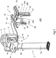
- Fig. 1 is a diagram that shows a perspective view of a related art extra-oral dental imaging system including a cephalometric imaging unit.
- an exemplary extra-oral dental imaging system 100 includes a support structure that can include a support column 1.
- the column 1 may be adjustable in two-dimensions or three-dimensions.
- the column 1 can be telescopic and may include an upper part 1b sliding inside a lower part 1a.
- a horizontal mount 2 may be supported or held by the vertical column 1 and can support a rotatable gantry 3.
- An x-ray source 4 and a first x-ray imaging sensor 5 can be attached or coupled to the gantry 3 in correspondence (e.g., opposite, aligned) to each other.
- the first x-ray sensor 5 may be a panoramic (e.g., slit-shaped) sensor or a Computerized Tomography (e.g., rectangular, square-shaped) sensor.
- the x-ray beam originating from the x-ray source 4 impinges the sensor 5 after radiating a first imaging area, a subject or the patient.
- a first patient positioning and holding system 6 can be operatively positioned near or in the first imaging area.
- the first patient positioning and holding system 6 may be between the x-ray source 4 and the first x-ray imaging sensor 5.
- the first patient positioning and holding system 6 can include a forehead support 7a and a shield 7b including two handles 7c and 7d. The patient can then grasp the handles 7c and 7d and remain motionless during the CT scan or panoramic scan.
- a cephalometric imaging unit 8 may be held in correspondence to the x-ray source 4.
- the cephalometric imaging unit 8 can be attached or coupled to the upper part 1b of the vertical column via an extended (e.g., horizontal) cephalometric arm 9.
- the cephalometric imaging unit 8 can include a mount 10 supporting a collimator 12, a second or cephalometric sensor 13 and a second patient positioning and holding system 14.
- the second patient positioning and holding system 14 can include a forehead support 17 and two temporal holding members 15a and 15b, each supporting an ear rod 16a and 16b.
- the x-ray beam originating from the x-ray source 4 impinges the sensor 13 after radiating a second or cephalometric imaging area or the patient.
- the second patient positioning and holding system 14 can be operatively positioned near or in the second imaging area.
- the patient is precisely and repeatedly positioned between the collimator 12 and the sensor 13, preferably in the second imaging area.
- One or more of the holding members 15a and 15b can respectively slide along rails 15ar and 15br so that the distance between the two ear rods 16a and 16b can be changed to fit the patient's head.
- the forehead support 17 can also be adjustable.
- the forehead support 17 can be adjustable at least in two orthogonal dimensions by sliding along the horizontal and vertical directions.
- the forehead support 17 can be adjustable in three-dimensions or around three or more orthogonal axis.
- the collimator 12 can include an elongated opening or slit 20 to shape an x-ray beam.
- the x-ray sensor 13 can include an active area 21 having an elongated shape (e.g., a vertical slit) facing the vertical slit 20 of the collimator 12 (e.g., across the second imaging area).
- the sensor 13 and the collimator 12 face each other so that the sensor 13 can receive the x-rays originating from the x-ray source 4 after the x-ray beam was shaped by the collimator 12 and after the x-ray beam radiated the patient positioned and held on the second patient's positioning and holding system 14.
- the collimator 12 can move or slide during the x-ray scan along a rail 22 and the sensor 13 can move or slide along the rail 23, both rails being coupled to the mount 10.
- the rails 22, 23 can be embodied on a lower face of the mount 10 of the cephalometric imaging unit 8.
- an alignment may exist between a primary collimator in front of the source (not shown), the slit 20 of the collimator 12 and the active area of the sensor 13.
- Such x-ray alignment is disclosed, for example, in US Patent no. 5511106 .
- an x-ray digital image is obtained by the sensor 13.
- an image reconstructing device e.g., hardware, software and/or image processing
- reconstructs the whole skull image on the basis of the plurality of images obtained during the cephalometric scan, for example using algorithms known to the person skilled in the art.
- the Frankfort plane containing a straight line passing though the bottom of the eye socket and the ear canal must be horizontal.
- an at least partially transparent visual indicator 30 can be used.
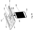
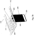
- Fig. 3a is a diagram that shows an ensemble cephalometric mount and an exemplary hand positioner embodiment in a disengaged state.
- Fig. 3b is a diagram that shows an ensemble cephalometric mount and an exemplary hand positioner embodiment in an engaged state.
- an exemplary hand positioner embodiment can be applied to the related art extra-oral dental imaging system shown in Fig. 1 .
- a hand's positioner 300 can include a plate 302 that is transparent to x-rays incorporated into a frame (e.g., made of aluminum, metal, rigid materials, plastic, etc) including two handles 303 and 304 so that the positioner 300 can be grasped or easily manipulated by the practitioner.
- a frame e.g., made of aluminum, metal, rigid materials, plastic, etc
- a protrusion 305 having a prescribed shape can be fixed to or integral with the positioner 300.
- the protrusion305 can be in the shape of a cone and can be fixed on one of the handles, namely handle 304.
- a cephalometric mount 110 can be affixed to a vertically adjustable base (not shown).
- Two rails 111 and 112 (on a lower surface of the mount 110) can allow the engagement and the sliding of respectively a collimator (not e.g., collimator 12) to shape the x-ray beam and an x-ray cephalometric sensor (e.g., sensor 13) having the shape of a thin rectangle.
- a cephalometric x-ray image is obtained by performing a scanning process including the accumulation of frames of the patient's skull or hand obtained continuously while the cephalometric sensor and the cephalometric collimator slide in a synchronized movement.
- a housing 114 of the mount 110 can be dedicated to attach or fix a patient's head positioning unit (not shown) (e.g., system 14) and a housing 113 can be provided for engaging the protrusion 305 of the hand positioner 300.
- Fig. 3b represents the ensemble composed of the cephalometric mount 110 and the hand's positioner 300 in the engaged position with the protrusion 305 in the housing 113 (e.g., with prescribed matching or interlocked shapes).
- Fig. 4 shows an enlarged view of the engagement of an exemplary hand positioner embodiment on the cephalometric mount.
- Fig. 5 shows a cross section of engagement of the hand positioner of Fig. 4 along line A-A'.
- a surface 150 of the cephalometric mount 110 can be provided with the housing 113 having an interior surface or bore in the shape of a hollow recess.
- the inner shape of the hollow recess in the housing 113 can have the general shape of a tapering conical bore 113a.
- a permanent magnet 123 is positioned or fixed within the hollow recess or tapering conical bore 113a.
- the permanent magnet 123 can be mounted (e.g., bottom surface) between a shoulder 115 provided inside the tapering conical bore 113a and (top or opposite surface) at least one fastener. As shown in Figs.
- the top surface of the magnet 123 is held against two screws 121a and 121b.
- the two screws 121a and 121b are fixed at diametrically opposed positions of the top surface 120 and press two rings 122a and 122b against the permanent magnet 123 (e.g., top surface).
- the magnet 123 can be sandwiched between the shoulder 115 and the two rings 122a and 122b.
- the top surface of the permanent magnet 123 slightly raises over (e.g., exceeds) the circular top surface 120 of the tapering conical bore 113a.
- the shoulder 115 extends only slightly into the tapering conical bore 113a so that a majority or substantially all of the permanent magnet 123 is exposed in the bore 113a.
- the shoulder 115 can cover, for example, 20%, most or all of the permanent magnet 123.
- other known methods of mounting the magnet 123 in the housing 113 can be used.
- the protrusion 305 of the hand positioner 300 can penetrate inside the conical bore 113a of the housing 113.
- the protrusion 305 can be made of aluminum and fixed on the handle 304 of the hand positioner 300.
- an outer lateral face 314 of the protrusion 305 can mate or engage with the inner face of the bore 113a, and preferably, the top face of the protrusion 305 comes into contact (or magnetic engagement) with the lower face of the permanent magnet 123.
- the protrusion 305 is provided with a mounting end 331 extending along an axis of symmetry of the protrusion 305.
- the mounting end 331 can include a threaded part 331a.
- a magnetic part can be inside the mounting end 331.
- a magnetic screw 330 e.g., iron screw
- a magnetic attraction is exerted by the permanent magnet 123 on the magnetic screw 330.
- the position of the magnetic screw 330 inside the threaded bore 331 of the protrusion 305 can be modified to change and/or monitor the magnetic attraction by the permanent magnet 123.
- the magnetic screw 330 must be close enough to the magnet 123 so that the attraction counter-balances the weight of the whole hand positioner 300.
- the hand positioner 300 is ready to be used for an x-ray imaging of the hand and the carpus of the patient.
- the attraction force can be too heavy and the dentist will have some difficulties to remove the hand positioner 300 from the cephalometric mount 110 (e.g., at the end of the carpus imaging process).
- adjustment of the attraction force can be manually (or automatically) performed by manually moving (e.g., turning, sliding) the magnetic screw to be closer or further from the magnet 123 when mounted.
- the adjustable attracted engagement force can be adjusted by increasing or decreasing a 3D distance between the attracted member and the magnetic attractor.
- Alternative ways of adjusting the attraction force can be contemplated, for example, by adding additional or removing magnetically attractable material to the protrusion 305 or the like.
- exemplary system and/or method embodiments according to the application can allow an easy positioning and/or easy removal of the hand positioner 300 compared to the complicated and bulky mechanisms of the prior art.
- the x-ray transparent plate 302 is parallel to the x-ray cephalometric sensor (not represented, sensor 13) engaged in the rail 112 so that the hand is projected on the plane of the cephalometric sensor without overlap of anatomical structures of the hand or the carpus.
- certain exemplary apparatus and/or method embodiments of the application provide a single mounting orientation and/or an sensory indication of proper mounting or installation of the hand positioner 300.
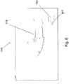
- Fig. 6 is a diagram that shows an enlarged view of the cephalometric mount representing a recess (e.g., slit) to engage an extension (e.g., arm) of an exemplary hand positioner embodiment in correct angular orientation.
- a transverse bar 340 extends orthogonally away from the protrusion 305 (see Fig. 4 ). As shown in Fig. 6 , the transverse bar 340 is configured to engage the slot 141 made on the surface 150 of the cephalometric mount 110 that joins (e.g., extends from) the bore 113a of the housing 113.
- the hand positioner 300 can be engaged in the bore 113a of the housing 113 on the surface 150 of the cephalometric mount 110 in one single possible angular position, ensuring that the surface 302 of the hand positioner 300 is parallel to an imaging plane of the cephalometric sensor.
- an indicator to verify mounting of the positioner 300 can be built into the cephalometric mount 110 or the hand positioner 300.
- an electrical switch 143 is provided on the surface 150 of the mount 110 at the vicinity of the housing 113. The electrical switch 143 can include a contact that extends up to the slot 141 (see Figs. 4 and 7 ).
- the transverse bar 340 When the hand positioner 300 is engaged to the mount 110, the transverse bar 340, which is electrically conductive, comes into contact with the contact of electrical switch 143, and consequently an electrical current travels through the switch 143 to be indicative of the correct engagement of the hand positioner 300.
- a corresponding information for the dentist can be displayed on a user's interface like a computer screen or using a visual indicator (e.g., light, red/green, etc.). Alternatively, an audible alert or corresponding information for the dentist can be broadcast on a user's interface like a speaker.
- the transverse bar 340 can be metallic or a conductive layer over at least one insulating or non-conductive core.
- a computer program utilizes stored instructions that perform on image data that is accessed from an electronic memory.
- a computer program for operating the imaging system in an exemplary embodiment of the present application can be utilized by a suitable, general-purpose computer system, such as a personal computer or workstation.
- a suitable, general-purpose computer system such as a personal computer or workstation.
- many other types of computer systems can be used to execute the computer program of the present application, including an arrangement of networked processors, for example.
- the computer program for performing exemplary methods/apparatus of the present application may be stored in a computer readable storage medium.
- This medium may comprise, for example; magnetic storage media such as a magnetic disk such as a hard drive or removable device or magnetic tape; optical storage media such as an optical disc, optical tape, or machine readable optical encoding; solid state electronic storage devices such as random access memory (RAM), or read only memory (ROM); or any other physical device or medium employed to store a computer program.
- the computer program for performing exemplary methods/apparatus of the present application may also be stored on computer readable storage medium that is connected to the image processor by way of the internet or other network or communication medium. Those skilled in the art will further readily recognize that the equivalent of such a computer program product may also be constructed in hardware.
- memory can refer to any type of temporary or more enduring data storage workspace used for storing and operating upon image data and accessible to a computer system, including a database, for example.
- the memory could be non-volatile, using, for example, a long-term storage medium such as magnetic or optical storage. Alternately, the memory could be of a more volatile nature, using an electronic circuit, such as random-access memory (RAM) that is used as a temporary buffer or workspace by a microprocessor or other control logic processor device.
- Display data for example, is typically stored in a temporary storage buffer that is directly associated with a display device and is periodically refreshed as needed in order to provide displayed data.
- This temporary storage buffer is also considered to be a type of memory, as the term is used in the present disclosure.
- Memory is also used as the data workspace for executing and storing intermediate and final results of calculations and other processing.
- Computer-accessible memory can be volatile, non-volatile, or a hybrid combination of volatile and non-volatile types.
- the computer program product of the present application may make use of various image manipulation algorithms and processes that are well known. It will be further understood that the computer program product embodiment of the present application may embody algorithms and processes not specifically shown or described herein that are useful for implementation. Such algorithms and processes may include conventional utilities that are within the ordinary skill of the image processing arts. Additional aspects of such algorithms and systems, and hardware and/or software for producing and otherwise processing the images or co-operating with the computer program product of the present application, are not specifically shown or described herein and may be selected from such algorithms, systems, hardware, components and elements known in the art.
- the first patient positioning and holding system 6 can include a substantially transparent shield suspended from the mount 2 or the rotatable gantry 3, and a chin positioning element that can include a chin rest and a bite element.
- the shield can include an open window disposed between a chin support and a forehead support.
- the shield can be visibly transparent, transparent to additional radiation including x-rays and/or formed from a molded polycarbonate material.
- the chin support can include a height adjuster for the bite element and the forehead support is configured to be adjustably pivotable toward the patient.
- the shield can include one or more controls for setting a column height adjustment for the mount on the shield or mounted on a separate panel that is coupled to the shield.
- the shield can include one or more markings to assist in patient positioning.
- the shield can include a first Frankfort plane positioning indicator.
- an extra-oral imaging system can include a support base adjustable in at least one dimension; a first mount mounted to the support base and configured to revolve an x-ray source and an imaging sensor panel about an imaging area; and a first patient positioning unit coupled to the extra-oral imaging system and positioned between the x-ray source and first sensor so that x-rays impinge the first sensor after radiating the imaging area, including a chin support coupled to the first patient positioning unit and includes a chin positioning element; a head support coupled to the first patient positioning unit shield; and a first Frankfort plan positioning indicator; a second mount mounted to the support base and configured to position a second imaging sensor panel about a second imaging area; and a second patient positioning unit coupled to the second mount and positioned between the x-ray source and the second sensor so that x-rays impinge the second sensor after radiating a second imaging area including a head support coupled to the second patient positioning unit; and a second Frankfort plane positioning indicator.
- the second Frankfort plane positioning indicator is fixedly mounted, detachably mounted, or mounted to move between at least two positions, or rotatably mounted.
- the second patient positioning unit is configured to repeatably and accurately position a patient between the x-ray source and the second imaging sensor panel.
- exemplary hand positioner device embodiments disclosed herein use a single arm and movement in a single direction to mount to the cephalometric mount.
- exemplary hand positioner device embodiments could use two or dual movements in orthogonal directions to install into the cephalometric mount with a selected orientation (e.g., without tools) and for example, gravity and a notched position to hold the prescribed alignment.
- the hand positioner device can include a mounting recess and an elongated recess oriented to extend along a first direction, where the cephalometric mount comprises an extension, and where the hand positioner device can be mounted to the cephalometric mount only when the extension is aligned with the first direction.
- exemplary apparatus and/or method embodiments according to the application have been described relative to a combined cephalometric, panoramic and computed tomography dental imaging apparatus, but are intended to be applicable to stand-alone cephalometric imaging applaratus or cephalometric imaging apparatus with any additional mode(s) of operation or functionality. The presently disclosed exemplary embodiments are therefore considered in all respects to be illustrative and not restrictive.
Landscapes
- Health & Medical Sciences (AREA)
- Life Sciences & Earth Sciences (AREA)
- Medical Informatics (AREA)
- Engineering & Computer Science (AREA)
- Nuclear Medicine, Radiotherapy & Molecular Imaging (AREA)
- Surgery (AREA)
- Veterinary Medicine (AREA)
- Biophysics (AREA)
- High Energy & Nuclear Physics (AREA)
- Public Health (AREA)
- General Health & Medical Sciences (AREA)
- Optics & Photonics (AREA)
- Pathology (AREA)
- Radiology & Medical Imaging (AREA)
- Biomedical Technology (AREA)
- Heart & Thoracic Surgery (AREA)
- Molecular Biology (AREA)
- Physics & Mathematics (AREA)
- Animal Behavior & Ethology (AREA)
- Dentistry (AREA)
- Oral & Maxillofacial Surgery (AREA)
- Orthopedic Medicine & Surgery (AREA)
- Apparatus For Radiation Diagnosis (AREA)
Applications Claiming Priority (2)
| Application Number | Priority Date | Filing Date | Title |
|---|---|---|---|
| US201462087374P | 2014-12-04 | 2014-12-04 | |
| PCT/IB2015/000339 WO2016087911A1 (en) | 2014-12-04 | 2015-01-14 | Hand positioner for cephalometric extra oral dental imaging devices |
Publications (2)
| Publication Number | Publication Date |
|---|---|
| EP3226771A1 EP3226771A1 (en) | 2017-10-11 |
| EP3226771B1 true EP3226771B1 (en) | 2018-12-12 |
Family
ID=52823699
Family Applications (1)
| Application Number | Title | Priority Date | Filing Date |
|---|---|---|---|
| EP15715402.2A Active EP3226771B1 (en) | 2014-12-04 | 2015-01-14 | Hand positioner for cephalometric extra oral dental imaging devices |
Country Status (5)
| Country | Link |
|---|---|
| US (1) | US10485495B2 (enExample) |
| EP (1) | EP3226771B1 (enExample) |
| JP (1) | JP2017536203A (enExample) |
| KR (1) | KR20170089873A (enExample) |
| WO (1) | WO2016087911A1 (enExample) |
Families Citing this family (3)
| Publication number | Priority date | Publication date | Assignee | Title |
|---|---|---|---|---|
| US10485495B2 (en) | 2014-12-04 | 2019-11-26 | Trophy | Hand positioner for cephalometric extra oral dental imaging devices |
| CN114441260B (zh) * | 2017-11-27 | 2025-01-28 | 徕卡生物系统成像股份有限公司 | 载片架确定系统 |
| US11000256B2 (en) * | 2018-11-09 | 2021-05-11 | Palodex Group Oy | Calibrating an X-ray medical imaging device for cephalometric imaging |
Family Cites Families (10)
| Publication number | Priority date | Publication date | Assignee | Title |
|---|---|---|---|---|
| EP0632995B1 (de) | 1993-07-06 | 1999-04-21 | Sirona Dental Systems GmbH & Co.KG | Zahnärztliche Röntgendiagnostikeinrichtung |
| AU2002358458A1 (en) * | 2001-12-10 | 2003-06-23 | Osteomate Aps | Method and apparatus for establishing an osteoporosis measure |
| US20090196395A1 (en) * | 2008-06-20 | 2009-08-06 | Gendex Corporation | Cephalometric x-ray imaging apparatus |
| JP5361059B2 (ja) | 2009-07-15 | 2013-12-04 | 朝日レントゲン工業株式会社 | X線撮影用頭部規格固定装置 |
| US8509381B2 (en) * | 2009-12-15 | 2013-08-13 | Midmark Corporation | Patient positioning system for panoramic dental radiation imaging system |
| WO2012082799A1 (en) * | 2010-12-13 | 2012-06-21 | Orthoscan, Inc. | Mobile fluoroscopic imaging system |
| ITBO20110765A1 (it) * | 2011-12-28 | 2013-06-29 | Cefla Coop | Apparato per radiografia dentale con accuratezza migliorata |
| ITMI20120099A1 (it) * | 2012-01-27 | 2013-07-28 | Gotzen S R L De | Apparato e metodo per radiografia digitale |
| US10485495B2 (en) | 2014-12-04 | 2019-11-26 | Trophy | Hand positioner for cephalometric extra oral dental imaging devices |
| JP2017529710A (ja) | 2015-07-31 | 2017-10-05 | エスゼット ディージェイアイ テクノロジー カンパニー リミテッドSz Dji Technology Co.,Ltd | 検索エリアを評価する方法 |
-
2015
- 2015-01-14 US US15/524,767 patent/US10485495B2/en active Active
- 2015-01-14 JP JP2017529710A patent/JP2017536203A/ja active Pending
- 2015-01-14 WO PCT/IB2015/000339 patent/WO2016087911A1/en not_active Ceased
- 2015-01-14 EP EP15715402.2A patent/EP3226771B1/en active Active
- 2015-01-14 KR KR1020177015005A patent/KR20170089873A/ko not_active Ceased
Non-Patent Citations (1)
| Title |
|---|
| None * |
Also Published As
| Publication number | Publication date |
|---|---|
| US10485495B2 (en) | 2019-11-26 |
| JP2017536203A (ja) | 2017-12-07 |
| WO2016087911A1 (en) | 2016-06-09 |
| EP3226771A1 (en) | 2017-10-11 |
| KR20170089873A (ko) | 2017-08-04 |
| US20170325760A1 (en) | 2017-11-16 |
Similar Documents
| Publication | Publication Date | Title |
|---|---|---|
| JP6297504B2 (ja) | デジタルラジオグラフィのための装置および方法 | |
| US20210338180A1 (en) | Stationary intraoral tomosynthesis imaging systems, methods, and computer readable media for three dimensional dental imaging | |
| KR102124669B1 (ko) | 부분적인 ct 이미징을 위한 장치 | |
| EP2835103A1 (en) | Imaging system and method for portable stereoscopic tomography | |
| CN106469253B (zh) | 用于显示位置信息的装置和方法 | |
| US20140079182A1 (en) | Patient head support apparatus for imaging | |
| EP3226771B1 (en) | Hand positioner for cephalometric extra oral dental imaging devices | |
| US10441227B2 (en) | Cephalostat | |
| US10537298B2 (en) | Method and device to adjust a cephalometric extra oral dental imaging devices | |
| US11045157B2 (en) | Visual indicator for the assessment of the tilt of the Frankfort plane in extra oral dental imaging devices | |
| EP3226770B1 (en) | Collimator for cephalometric extra oral dental imaging devices | |
| CN202751407U (zh) | 牙科ct成像x射线源角度调整装置 | |
| US10420525B2 (en) | Method and apparatus for aligning of cephalometric imaging device collimator | |
| EP3261543B1 (en) | Bite block for cbct imaging device | |
| US20170332985A1 (en) | Cephalometric patient positioning unit extra oral dental imaging devices | |
| EP2221004A1 (en) | Centering unit particularly for radiographic instruments |
Legal Events
| Date | Code | Title | Description |
|---|---|---|---|
| STAA | Information on the status of an ep patent application or granted ep patent |
Free format text: STATUS: THE INTERNATIONAL PUBLICATION HAS BEEN MADE |
|
| PUAI | Public reference made under article 153(3) epc to a published international application that has entered the european phase |
Free format text: ORIGINAL CODE: 0009012 |
|
| STAA | Information on the status of an ep patent application or granted ep patent |
Free format text: STATUS: REQUEST FOR EXAMINATION WAS MADE |
|
| 17P | Request for examination filed |
Effective date: 20170531 |
|
| AK | Designated contracting states |
Kind code of ref document: A1 Designated state(s): AL AT BE BG CH CY CZ DE DK EE ES FI FR GB GR HR HU IE IS IT LI LT LU LV MC MK MT NL NO PL PT RO RS SE SI SK SM TR |
|
| AX | Request for extension of the european patent |
Extension state: BA ME |
|
| DAX | Request for extension of the european patent (deleted) | ||
| GRAP | Despatch of communication of intention to grant a patent |
Free format text: ORIGINAL CODE: EPIDOSNIGR1 |
|
| STAA | Information on the status of an ep patent application or granted ep patent |
Free format text: STATUS: GRANT OF PATENT IS INTENDED |
|
| INTG | Intention to grant announced |
Effective date: 20180712 |
|
| GRAS | Grant fee paid |
Free format text: ORIGINAL CODE: EPIDOSNIGR3 |
|
| GRAA | (expected) grant |
Free format text: ORIGINAL CODE: 0009210 |
|
| STAA | Information on the status of an ep patent application or granted ep patent |
Free format text: STATUS: THE PATENT HAS BEEN GRANTED |
|
| AK | Designated contracting states |
Kind code of ref document: B1 Designated state(s): AL AT BE BG CH CY CZ DE DK EE ES FI FR GB GR HR HU IE IS IT LI LT LU LV MC MK MT NL NO PL PT RO RS SE SI SK SM TR |
|
| REG | Reference to a national code |
Ref country code: GB Ref legal event code: FG4D |
|
| REG | Reference to a national code |
Ref country code: CH Ref legal event code: EP |
|
| REG | Reference to a national code |
Ref country code: AT Ref legal event code: REF Ref document number: 1074947 Country of ref document: AT Kind code of ref document: T Effective date: 20181215 |
|
| REG | Reference to a national code |
Ref country code: DE Ref legal event code: R096 Ref document number: 602015021258 Country of ref document: DE |
|
| REG | Reference to a national code |
Ref country code: IE Ref legal event code: FG4D |
|
| REG | Reference to a national code |
Ref country code: NL Ref legal event code: MP Effective date: 20181212 |
|
| REG | Reference to a national code |
Ref country code: LT Ref legal event code: MG4D |
|
| PG25 | Lapsed in a contracting state [announced via postgrant information from national office to epo] |
Ref country code: BG Free format text: LAPSE BECAUSE OF FAILURE TO SUBMIT A TRANSLATION OF THE DESCRIPTION OR TO PAY THE FEE WITHIN THE PRESCRIBED TIME-LIMIT Effective date: 20190312 Ref country code: HR Free format text: LAPSE BECAUSE OF FAILURE TO SUBMIT A TRANSLATION OF THE DESCRIPTION OR TO PAY THE FEE WITHIN THE PRESCRIBED TIME-LIMIT Effective date: 20181212 Ref country code: LT Free format text: LAPSE BECAUSE OF FAILURE TO SUBMIT A TRANSLATION OF THE DESCRIPTION OR TO PAY THE FEE WITHIN THE PRESCRIBED TIME-LIMIT Effective date: 20181212 Ref country code: NO Free format text: LAPSE BECAUSE OF FAILURE TO SUBMIT A TRANSLATION OF THE DESCRIPTION OR TO PAY THE FEE WITHIN THE PRESCRIBED TIME-LIMIT Effective date: 20190312 Ref country code: LV Free format text: LAPSE BECAUSE OF FAILURE TO SUBMIT A TRANSLATION OF THE DESCRIPTION OR TO PAY THE FEE WITHIN THE PRESCRIBED TIME-LIMIT Effective date: 20181212 Ref country code: FI Free format text: LAPSE BECAUSE OF FAILURE TO SUBMIT A TRANSLATION OF THE DESCRIPTION OR TO PAY THE FEE WITHIN THE PRESCRIBED TIME-LIMIT Effective date: 20181212 |
|
| REG | Reference to a national code |
Ref country code: AT Ref legal event code: MK05 Ref document number: 1074947 Country of ref document: AT Kind code of ref document: T Effective date: 20181212 |
|
| PG25 | Lapsed in a contracting state [announced via postgrant information from national office to epo] |
Ref country code: AL Free format text: LAPSE BECAUSE OF FAILURE TO SUBMIT A TRANSLATION OF THE DESCRIPTION OR TO PAY THE FEE WITHIN THE PRESCRIBED TIME-LIMIT Effective date: 20181212 Ref country code: SE Free format text: LAPSE BECAUSE OF FAILURE TO SUBMIT A TRANSLATION OF THE DESCRIPTION OR TO PAY THE FEE WITHIN THE PRESCRIBED TIME-LIMIT Effective date: 20181212 Ref country code: RS Free format text: LAPSE BECAUSE OF FAILURE TO SUBMIT A TRANSLATION OF THE DESCRIPTION OR TO PAY THE FEE WITHIN THE PRESCRIBED TIME-LIMIT Effective date: 20181212 Ref country code: GR Free format text: LAPSE BECAUSE OF FAILURE TO SUBMIT A TRANSLATION OF THE DESCRIPTION OR TO PAY THE FEE WITHIN THE PRESCRIBED TIME-LIMIT Effective date: 20190313 |
|
| PG25 | Lapsed in a contracting state [announced via postgrant information from national office to epo] |
Ref country code: NL Free format text: LAPSE BECAUSE OF FAILURE TO SUBMIT A TRANSLATION OF THE DESCRIPTION OR TO PAY THE FEE WITHIN THE PRESCRIBED TIME-LIMIT Effective date: 20181212 |
|
| PG25 | Lapsed in a contracting state [announced via postgrant information from national office to epo] |
Ref country code: IT Free format text: LAPSE BECAUSE OF FAILURE TO SUBMIT A TRANSLATION OF THE DESCRIPTION OR TO PAY THE FEE WITHIN THE PRESCRIBED TIME-LIMIT Effective date: 20181212 Ref country code: PL Free format text: LAPSE BECAUSE OF FAILURE TO SUBMIT A TRANSLATION OF THE DESCRIPTION OR TO PAY THE FEE WITHIN THE PRESCRIBED TIME-LIMIT Effective date: 20181212 Ref country code: ES Free format text: LAPSE BECAUSE OF FAILURE TO SUBMIT A TRANSLATION OF THE DESCRIPTION OR TO PAY THE FEE WITHIN THE PRESCRIBED TIME-LIMIT Effective date: 20181212 Ref country code: CZ Free format text: LAPSE BECAUSE OF FAILURE TO SUBMIT A TRANSLATION OF THE DESCRIPTION OR TO PAY THE FEE WITHIN THE PRESCRIBED TIME-LIMIT Effective date: 20181212 Ref country code: PT Free format text: LAPSE BECAUSE OF FAILURE TO SUBMIT A TRANSLATION OF THE DESCRIPTION OR TO PAY THE FEE WITHIN THE PRESCRIBED TIME-LIMIT Effective date: 20190412 |
|
| PG25 | Lapsed in a contracting state [announced via postgrant information from national office to epo] |
Ref country code: RO Free format text: LAPSE BECAUSE OF FAILURE TO SUBMIT A TRANSLATION OF THE DESCRIPTION OR TO PAY THE FEE WITHIN THE PRESCRIBED TIME-LIMIT Effective date: 20181212 Ref country code: IS Free format text: LAPSE BECAUSE OF FAILURE TO SUBMIT A TRANSLATION OF THE DESCRIPTION OR TO PAY THE FEE WITHIN THE PRESCRIBED TIME-LIMIT Effective date: 20190412 Ref country code: SK Free format text: LAPSE BECAUSE OF FAILURE TO SUBMIT A TRANSLATION OF THE DESCRIPTION OR TO PAY THE FEE WITHIN THE PRESCRIBED TIME-LIMIT Effective date: 20181212 Ref country code: SM Free format text: LAPSE BECAUSE OF FAILURE TO SUBMIT A TRANSLATION OF THE DESCRIPTION OR TO PAY THE FEE WITHIN THE PRESCRIBED TIME-LIMIT Effective date: 20181212 Ref country code: EE Free format text: LAPSE BECAUSE OF FAILURE TO SUBMIT A TRANSLATION OF THE DESCRIPTION OR TO PAY THE FEE WITHIN THE PRESCRIBED TIME-LIMIT Effective date: 20181212 |
|
| REG | Reference to a national code |
Ref country code: CH Ref legal event code: PL |
|
| REG | Reference to a national code |
Ref country code: DE Ref legal event code: R097 Ref document number: 602015021258 Country of ref document: DE |
|
| PG25 | Lapsed in a contracting state [announced via postgrant information from national office to epo] |
Ref country code: LU Free format text: LAPSE BECAUSE OF NON-PAYMENT OF DUE FEES Effective date: 20190114 |
|
| REG | Reference to a national code |
Ref country code: BE Ref legal event code: MM Effective date: 20190131 |
|
| PLBE | No opposition filed within time limit |
Free format text: ORIGINAL CODE: 0009261 |
|
| STAA | Information on the status of an ep patent application or granted ep patent |
Free format text: STATUS: NO OPPOSITION FILED WITHIN TIME LIMIT |
|
| REG | Reference to a national code |
Ref country code: IE Ref legal event code: MM4A |
|
| PG25 | Lapsed in a contracting state [announced via postgrant information from national office to epo] |
Ref country code: DK Free format text: LAPSE BECAUSE OF FAILURE TO SUBMIT A TRANSLATION OF THE DESCRIPTION OR TO PAY THE FEE WITHIN THE PRESCRIBED TIME-LIMIT Effective date: 20181212 Ref country code: AT Free format text: LAPSE BECAUSE OF FAILURE TO SUBMIT A TRANSLATION OF THE DESCRIPTION OR TO PAY THE FEE WITHIN THE PRESCRIBED TIME-LIMIT Effective date: 20181212 Ref country code: SI Free format text: LAPSE BECAUSE OF FAILURE TO SUBMIT A TRANSLATION OF THE DESCRIPTION OR TO PAY THE FEE WITHIN THE PRESCRIBED TIME-LIMIT Effective date: 20181212 Ref country code: MC Free format text: LAPSE BECAUSE OF FAILURE TO SUBMIT A TRANSLATION OF THE DESCRIPTION OR TO PAY THE FEE WITHIN THE PRESCRIBED TIME-LIMIT Effective date: 20181212 |
|
| 26N | No opposition filed |
Effective date: 20190913 |
|
| PG25 | Lapsed in a contracting state [announced via postgrant information from national office to epo] |
Ref country code: BE Free format text: LAPSE BECAUSE OF NON-PAYMENT OF DUE FEES Effective date: 20190131 |
|
| PG25 | Lapsed in a contracting state [announced via postgrant information from national office to epo] |
Ref country code: CH Free format text: LAPSE BECAUSE OF NON-PAYMENT OF DUE FEES Effective date: 20190131 Ref country code: LI Free format text: LAPSE BECAUSE OF NON-PAYMENT OF DUE FEES Effective date: 20190131 |
|
| PG25 | Lapsed in a contracting state [announced via postgrant information from national office to epo] |
Ref country code: IE Free format text: LAPSE BECAUSE OF NON-PAYMENT OF DUE FEES Effective date: 20190114 |
|
| PG25 | Lapsed in a contracting state [announced via postgrant information from national office to epo] |
Ref country code: TR Free format text: LAPSE BECAUSE OF FAILURE TO SUBMIT A TRANSLATION OF THE DESCRIPTION OR TO PAY THE FEE WITHIN THE PRESCRIBED TIME-LIMIT Effective date: 20181212 |
|
| PG25 | Lapsed in a contracting state [announced via postgrant information from national office to epo] |
Ref country code: MT Free format text: LAPSE BECAUSE OF NON-PAYMENT OF DUE FEES Effective date: 20190114 |
|
| PGFP | Annual fee paid to national office [announced via postgrant information from national office to epo] |
Ref country code: GB Payment date: 20201231 Year of fee payment: 7 |
|
| PG25 | Lapsed in a contracting state [announced via postgrant information from national office to epo] |
Ref country code: CY Free format text: LAPSE BECAUSE OF FAILURE TO SUBMIT A TRANSLATION OF THE DESCRIPTION OR TO PAY THE FEE WITHIN THE PRESCRIBED TIME-LIMIT Effective date: 20181212 |
|
| PG25 | Lapsed in a contracting state [announced via postgrant information from national office to epo] |
Ref country code: HU Free format text: LAPSE BECAUSE OF FAILURE TO SUBMIT A TRANSLATION OF THE DESCRIPTION OR TO PAY THE FEE WITHIN THE PRESCRIBED TIME-LIMIT; INVALID AB INITIO Effective date: 20150114 |
|
| PG25 | Lapsed in a contracting state [announced via postgrant information from national office to epo] |
Ref country code: MK Free format text: LAPSE BECAUSE OF FAILURE TO SUBMIT A TRANSLATION OF THE DESCRIPTION OR TO PAY THE FEE WITHIN THE PRESCRIBED TIME-LIMIT Effective date: 20181212 |
|
| GBPC | Gb: european patent ceased through non-payment of renewal fee |
Effective date: 20220114 |
|
| PG25 | Lapsed in a contracting state [announced via postgrant information from national office to epo] |
Ref country code: GB Free format text: LAPSE BECAUSE OF NON-PAYMENT OF DUE FEES Effective date: 20220114 |
|
| REG | Reference to a national code |
Ref country code: DE Ref legal event code: R079 Ref document number: 602015021258 Country of ref document: DE Free format text: PREVIOUS MAIN CLASS: A61B0006140000 Ipc: A61B0006510000 |
|
| PGFP | Annual fee paid to national office [announced via postgrant information from national office to epo] |
Ref country code: FR Payment date: 20241216 Year of fee payment: 11 |
|
| PGFP | Annual fee paid to national office [announced via postgrant information from national office to epo] |
Ref country code: DE Payment date: 20241217 Year of fee payment: 11 |