EP3225920A1 - Extractor hood - Google Patents
Extractor hood Download PDFInfo
- Publication number
- EP3225920A1 EP3225920A1 EP17158174.7A EP17158174A EP3225920A1 EP 3225920 A1 EP3225920 A1 EP 3225920A1 EP 17158174 A EP17158174 A EP 17158174A EP 3225920 A1 EP3225920 A1 EP 3225920A1
- Authority
- EP
- European Patent Office
- Prior art keywords
- protective grid
- air
- extractor
- protective
- extractor hood
- Prior art date
- Legal status (The legal status is an assumption and is not a legal conclusion. Google has not performed a legal analysis and makes no representation as to the accuracy of the status listed.)
- Withdrawn
Links
Images


Classifications
-
- F—MECHANICAL ENGINEERING; LIGHTING; HEATING; WEAPONS; BLASTING
- F24—HEATING; RANGES; VENTILATING
- F24C—DOMESTIC STOVES OR RANGES ; DETAILS OF DOMESTIC STOVES OR RANGES, OF GENERAL APPLICATION
- F24C15/00—Details
- F24C15/20—Removing cooking fumes
-
- F—MECHANICAL ENGINEERING; LIGHTING; HEATING; WEAPONS; BLASTING
- F24—HEATING; RANGES; VENTILATING
- F24C—DOMESTIC STOVES OR RANGES ; DETAILS OF DOMESTIC STOVES OR RANGES, OF GENERAL APPLICATION
- F24C15/00—Details
- F24C15/20—Removing cooking fumes
- F24C15/2035—Arrangement or mounting of filters
-
- F—MECHANICAL ENGINEERING; LIGHTING; HEATING; WEAPONS; BLASTING
- F24—HEATING; RANGES; VENTILATING
- F24C—DOMESTIC STOVES OR RANGES ; DETAILS OF DOMESTIC STOVES OR RANGES, OF GENERAL APPLICATION
- F24C15/00—Details
- F24C15/20—Removing cooking fumes
- F24C15/2071—Removing cooking fumes mounting of cooking hood
Definitions
- the present invention relates to an extractor hood.
- extractor hoods required for sucking the air to be cleaned vacuum is generated by a blower.
- the blower is usually operated electrically and has a rotating fan wheel.
- a protective grid is usually provided in the hood.
- Such a protective grid is for example in the DE 10 2007 021 318 A1 described.
- a disadvantage of this known protective grid is that this reduces the achievable with the blower delivery volume.
- Object of the present invention is therefore to provide a cooker hood, in which a reliable protection of the user is ensured at the same time optimal operation of the hood.
- the invention is based on the finding that this object can be achieved by the protective grid influences the air flow to the fan so that it reaches the fan with the least possible loss or without loss.
- an extractor hood comprising a fume hood housing with a suction port, a blower with at least one air inlet opening and a protective grid.
- the extractor hood is characterized in that the protective grid is attached to the extractor housing, the protective grille is secured to the at least one air inlet opening vertically in the suction opening, the protective grille completely covers the suction opening and the protective grid has at least one air guide element between the inlet side of the protective grid and the exit side of the protective grid is at least partially curved.
- the extractor hood As an extractor hood according to the invention a device for sucking and cleaning of contaminated air understood, in particular understood by fumes and vapors that arise during cooking.
- the extractor hood includes a cooker hood housing with a suction opening, through which the air to be cleaned is sucked into the interior of the extractor hood.
- a fan is arranged, which can represent, for example, a one-sided or two-sided radial fan.
- the fan consists of one or more fans, each having at least one fan and a fan housing. At least one air inlet opening is provided in the fan housing.
- the blower housing has an air outlet opening which, in the case of a radial blower designed as a spiral blower, lies in particular on an air outlet duct and is perpendicular to the air inlet opening or openings.
- the at least one air inlet opening preferably represents a circular opening.
- the extractor hood according to the invention comprises a protective grid.
- the protective grid is attached to the extractor housing.
- advantages over engagement protectors provided directly on the blower can be provided. Namely, such devices have significant disadvantages. Thus, these always lead to a performance deterioration, since the inflow of air is disturbed directly at the fan.
- the protective grid is attached to the extractor housing so that it completely covers the intake opening of the extractor housing.
- an arrangement of the protective grid in the suction port is referred to, in which the edges of the protective grid are offset at the edges of the suction port or to the edges of the suction port to the outside.
- the surface formed by the protective grille completely covers the suction opening. Also by this design and arrangement of the protective grille there are significant advantages over safety devices provided on the fan, since the interior of the device is not accessible in this embodiment. This means that no separate measures have to be taken to secure cables, for example. In addition, at This embodiment also no sheet metal edges accessible to the user of the hood, which could injure and disturb the user when cleaning the hood.
- the protective grid is in the extractor hood according to the invention perpendicular to the at least one air inlet opening of the blower.
- the blower is a spiral blower
- part of the outer periphery of the spiral casing may face the protective grid and the air intake opening (s) provided in the one or more sides are perpendicular to the surface of the protective grid.
- the air exiting the protective grille flows at least partially parallel to the surface of the air inlet opening.
- a protective grid is understood to be a component in which grid elements extend at least in one direction and in which passage openings for air are formed between the grid elements.
- the protective grid has at least one air guiding element.
- the air guide element forms a grid element of the protective grid and is fixedly mounted in the protective grid.
- a plurality of air guide elements are provided.
- An air guiding element is an element which at least partially alters the direction of the air flow passing through the protective grille.
- the at least one air-guiding element is curved at least in regions between the inlet side of the protective grid and the outlet side of the protective grid.
- the entry side of the protective grille is the side facing outwards in the installed state of the protective grille on the extractor housing and via which the air flow drawn in enters.
- the exit side is the side of the protective grid which faces the interior of the extractor housing in the assembled state of the protective grid on the extractor housing and via which the aspirated air stream exits from the protective grid.
- the at least one air guide element is shaped so that it is curved between the inlet side and the outlet side.
- the distance between the inlet side and the outlet side is also referred to as the thickness or height of the protective grid.
- the radius of curvature of the air guide element can be constant between the inlet side and the outlet side, that is to say over the height of the protective grid. However, it is also within the scope of the invention that the Radius of curvature changes over the height of the protective grid, that varies over the height.
- the at least one air guiding element preferably represents a lamella.
- the lamella in this case has a curved cross section.
- a lamella is a strip of material which has a longitudinal extent, that is to say has a larger dimension in one direction than in the other two directions.
- the lamella or lamellae are preferably arranged in the protective grid in such a way that their longitudinal extension lies in the horizontal direction in the mounted state of the protective grid in the extractor hood.
- the air flow passing through the protective grid can be changed in its main flow direction so that the outgoing air flow is inclined to the surface of the protective grid.
- this change in direction which is effected in the protective grid, it is possible to direct the exiting air flow as a directed air flow to the fan.
- the air flow in the protective grid used in the invention can be output so that it can be sucked with minimal losses to the fan.
- the performance of the hood is not impaired and ideally even improved.
- the delivery volume and the efficiency are referred to as the performance of the extractor hood, which are at least not worsened or, preferably, even improved.
- the reduction of noise to the performance of the hood can be expected.
- the at least one air guiding element is oriented and shaped in such a way that a directed air flow is emitted through the protective grid, the main flow direction of which is offset from the center of the air inlet opening of the blower.
- Directed air flow is an air flow which has a main flow direction in which the largest volume part of the air flow flows.
- the main flow direction extends in this preferred embodiment offset to the center of the air inlet opening of the blower.
- a main flow direction is designated, which is aligned at the air inlet opening at least in regions such that it does not run at the center of the air inlet opening at the air inlet opening.
- the at least one air guiding element is shaped and aligned such that the main flow direction is inclined downwards towards the center of the air inlet opening.
- the fan and in particular the fan wheel is arranged in the fan housing.
- the air inlet opening is here aligned with the fan.
- the axis of the fan wheel is preferably located in the center of the air inlet opening.
- the fan is preferably rotated or rotated so that the fan blades rotate in the direction that is directed to the protective grid. If the protective grille is in a vertical plan view of the air inlet opening, for example on the left side of the fan, the fan is preferably rotated counterclockwise. If the protective grille is in a vertical plan view of the air inlet opening, for example on the right side of the fan, the fan is preferably rotated in a clockwise direction. In either case, an airflow whose main flow direction is parallel to the air inlet opening and down to the center point, when entering the fan, will strike in the direction of the fan wheels in which they are moving.
- the main flow direction of the air flow from the protective grid can be adjusted by the protective grid so that the main flow direction, for example, in a vertical plan view of the air inlet opening tangent to the surface of the air inlet opening or the main flow direction intersects the circular surface of the air inlet opening in vertical plan view of the air inlet opening as a secant.
- the airflow can be brought in a direction corresponding to the main suction direction of the blower Turbulences that lead to a reduction of the delivery volume are prevented.
- the main suction direction of the blower is determined by the direction of movement of the fan wheel.
- a plurality of air guiding elements are arranged parallel to one another in the protective grid. By having the air directing elements aligned in parallel, uniform entry of air into the protective grid across the surface of the protective grille can be ensured.
- the protective grid on several air guide elements and all air guide elements of the protective grid have the same shape. Also by this configuration, a uniform flow is effected.
- the protective grid has at least one reinforcing strut.
- the at least one reinforcing strut is arranged twisted in the protective grid relative to the at least one air guiding element.
- a reinforcing strut is referred to as being twisted, the longitudinal extent of which is at an angle to the longitudinal extent of the at least one air guiding element in a vertical plan view on the inlet side or outlet side of the protective grid which is greater than zero and not equal to 180 °.
- the longitudinal extension of the at least one reinforcing strut is perpendicular to the longitudinal extension of the at least one air guide element.
- the stability of the protective grid can be improved.
- a bending of the or the air guide elements can be reliably prevented.
- the distance between air guide elements can be fixed by the reinforcing struts.
- the at least one reinforcing strut has a lower height than the at least one air guiding element.
- the at least one reinforcing strut is arranged on the outlet side of the protective grid. In this case, the reinforcing strut extends from the outlet side in the direction of the inlet side of the protective grid.
- the protective grid has at least two air guide elements and the air guide elements cover the surface of the protective grid in a vertical plan view of the entry side of the protective grid.
- the air guiding elements preferably cover the surface of the protective grid in the horizontal direction.
- the protective grid is secured by means of latching connection and / or clamping connection to the extractor housing.
- latching connection and / or clamping connection to the extractor housing.
- the protective grid has at least one fastening device for fastening at least one filter element.
- the structure of the extractor hood is further simplified.
- the performance of the hood can be improved as a result, since separate fastening devices for filter elements, which would lead to a further obstruction of the air flow, can be prevented.
- the suction opening and the protective grid are aligned in the extractor housing in a direction inclined to the horizontal, the fan is in the horizontal direction behind the suction port and the at least one air guide is from the inlet side to the outlet side of the protective grid in the state attached to the suction port curved from an upward inclined direction in a downward inclined direction.
- the embodiment of the extractor hood, in which the suction opening is oriented in a direction pivoted to the horizontal direction, is also referred to as an oblique hood or inclined hood.
- the vapor which usually rises vertically upwards, flows from below to the inclined intake opening.
- the protective grid is aligned in a direction inclined to the horizontal direction and preferably parallel to the suction port is located, the Wrasen or cleaned by a possibly provided filter element air and the protective grid to flow substantially vertically from below. Due to the curvature of the air guide elements, a vertical impact on the air guide element is prevented when the air impinges on the inlet side of the protective grille. In addition, due to the further curvature of the air guide element, a deflection of the air flow in a downwardly inclined direction. The thus emerging air flow may therefore be directed to the lower region of a blower arranged behind the suction opening.
- FIG. 1 is a schematic front view of an embodiment of the extractor hood 1 according to the invention shown.
- the extractor hood 1 comprises a fume hood housing 10 and a vapor shield 11.
- a suction opening 17 is introduced.
- a baffle plate 12 which is arranged in the operation of the extractor hood 1 in front of the suction opening 17, folded upwards.
- a suction port 14 is introduced in the extractor housing 10 in the suction opening 14, a protective grid 15 is introduced. From the protective grid 15, the inlet side 153 can be seen in the illustrated embodiment.
- the inlet side 153 is formed by the longitudinal edges of extending in the width direction of the hood 1 air guide elements 150, which are also referred to below as fins.
- FIG. 2 is a schematic sectional view of an embodiment of the hood 1 shown. Also in this embodiment, the extractor hood 1 is formed by a fume hood housing 10 and a Wrasentran 11. The vapor shield 11 is inclined in the illustrated embodiment from the horizontal upwards.
- a fan 16 is arranged in the extractor housing 10.
- the blower 16 has an air inlet port 160, which is a circular opening, and an air outlet port 161 formed on the housing of the blower 16. Inside the blower housing a fan (not visible) is arranged.
- a suction port 14 is formed, which is offset to the suction opening 17 of the vapor shield 11 to the rear.
- baffle plate 12 is provided in front of the vapor shield 11 and in particular in front of the suction opening 17 at a distance from the vapor shield 11 .
- a baffle plate 12 is provided in front of the vapor shield 11 and in particular in front of the suction opening 17 at a distance from the vapor shield 11 .
- a grease filter 13 is arranged in front of the suction opening 14 in the extractor housing 10. Behind the grease filter 13 and in the suction port 14, a protective grid 15 is introduced.
- the grease filter 13 may, for example, connected to the protective grid 15, that is to be attached to this.
- the protective grid 15 is attached to the extractor housing 10 and has a size which completely covers the intake opening 14.
- the blower 16 constitutes a spiral blower.
- the blower 16 is arranged in the extractor housing 10 such that the air inlet opening 160 is perpendicular to the protective grid 15.
- the fan 16 is arranged in the horizontal direction behind the suction opening in the extractor housing 10.
- the protective grid 15 consists of a plurality of air guide elements 150 whose longitudinal extent lies in the horizontal.
- the air guide elements 150 each have a shape curved over the height thereof.
- the height of the protective grid 15, the dimension of the protective grid 15 is referred to, which is perpendicular to the surface of the protective grid 15.
- the vertical distance between the inlet side 153 and the outlet side 154 of the protective grid 15 is referred to as height.
- FIG. 2 are schematically indicated the currents that are achieved with the embodiment of the hood 1.
- the fumes and vapor After the fumes and vapor have flowed through the grease filter 13, they come as purified air in the inlet side 153 of the protective grid 15 and are output on the outlet side 154 of the protective grid 15.
- Due to the curvature of the air guide elements 150 the initially vertically upward flow of steam in the extractor housing is present as a slightly upward air flow or horizontal air flow.
- the main flow direction H of the air flow is in FIG. 2 shown schematically.
- the main flow direction H of the air flow is directed to the lower region of the air inlet opening 160 of the blower 16, that is, the main flow direction H extends in a vertical plan view of the air inlet opening 160 to the center of the air inlet opening 160 downwardly offset.
- the fan (not shown) of the blower 16 is in the in FIG. 2 shown embodiment rotated counterclockwise.
- a vortex-shaped suction is formed via the fan wheel (not shown) provided therein. Due to the curvature of the air guiding elements 150, the air drawn in by the protective grille 15 is oriented so that it is tangential or secant hits the suction and thus forms a vortex. The air is discharged from the extractor hood 1 after passing through the fan wheel through the air outlet channel 161.
- the protective grid 15 has this transversely extending air guide elements 150, a plurality of reinforcing struts 151.
- the reinforcing struts 151 extend perpendicular to the longitudinal extension of the air guide elements 150 and are therefore also referred to as vertical struts. In the illustrated embodiment, the reinforcing struts 151 protrude beyond the rear longitudinal edges of the spoiler elements 150.
- the connection is produced by sliding hooks 101 and latching hook 100 on the extractor housing 11, which engage in corresponding openings on the protective grid 15.
- the air guide elements 150 are held on the reinforcing struts 151.
- the height of the reinforcing struts 151 is smaller than the height of the Luftleitelemetente 150.
- an extractor hood in which a protective system is implemented by a protective grid, which prevents the customer touches rotating parts such as the fan and live parts.
- This protective grille which can also be referred to as anti-tampering, can cause as little or no loss in performance as possible, despite interference with the air duct of the extractor hood.
- the guard will even achieve improved performance.
- additional functions such as the filter holder or filter holder, for example, of grease and / or circulating air filters on the protective grid and a filter seal are possible.
- the hood also cleanability is improved and created a privacy through the guard.
- the shape of the air-guiding elements that is to say the lamella shape
- the slats must meet several parts of conflicting requirements. Basically, these have to fulfill all safety requirements of VDE, which demands a high stability and fixed connection to the housing.
- the protective grid must also prevent the user from reaching into the rotating fan wheel or to live components. For this purpose, usually a high material usage and small distances between the slats are necessary. However, the small clearance between the blades and the high material usage increase the obstruction area in the intake area, which leads to a deterioration in the performance values (delivery volume, noise, efficiency).
- the air guide elements that is to say slats
- the fins of the protective grid are preferably designed so that the properties of the fan are optimally supported, that is, the sucked air is placed in a twist and passes lossless in the fan.
- the protective grid can preferably be mounted without screws. This is implemented, for example, via a sliding latching closure, in which, for example, sliding lugs and / or latching hooks are used.
- a good privacy in the cooker hood can also be supplied through the protective grille and enhances the visual appearance of the cooker hood.
- cables will be covered so that they are not visible from the outside. This requirement is again in conflict with the barrier area and has been implemented taking into account the performance values to be achieved.
- the invention thus has a number of advantages.
- the user is protected against mechanical and electrical hazards. Simple cleaning of the protective grid is possible.
- the mounting of the protective grille can be screwless.
- a performance improvement by the geometry of the air guide elements which can also be referred to as Leitgeometrie achieved, while maintaining or improving the delivery volume and efficiency and minimizes noise, for example.
- the interior of the extractor hood preferably can not be accessible, so that the protective grid also serves as a privacy screen for the interior.
Landscapes
- Engineering & Computer Science (AREA)
- Chemical & Material Sciences (AREA)
- Combustion & Propulsion (AREA)
- Mechanical Engineering (AREA)
- General Engineering & Computer Science (AREA)
- Ventilation (AREA)
Abstract
Die vorliegende Erfindung betrifft eine Dunstabzugshaube umfassend ein Dunstabzugsgehäuse (10) mit einer Ansaugöffnung (14), ein Gebläse (16) mit mindestens einer Lufteinlassöffnung (160) und ein Schutzgitter (15), das an dem Dunstabzugsgehäuse (10) angebracht ist. Die Dunstabzugshaube ist dadurch gekennzeichnet, dass das Schutzgitter (15) zu der mindestens einen Lufteinlassöffnung (160) des Gebläses (16) senkrecht in der Ansaugöffnung (14) befestigt ist, das Schutzgitter (15) die Ansaugöffnung (14) vollständig abdeckt und das Schutzgitter (15) mindestens ein Luftleitelement (150) aufweist, das zwischen der Eintrittsseite (153) des Schutzgitters (15) und der Austrittsseite (154) des Schutzgitters (15) zumindest bereichsweise gekrümmt ist.The present invention relates to an extractor hood comprising a fume hood housing (10) with a suction opening (14), a fan (16) with at least one air inlet opening (160) and a protective grid (15) attached to the fume hood housing (10). The extractor hood is characterized in that the protective grid (15) to the at least one air inlet opening (160) of the blower (16) is mounted vertically in the suction opening (14), the protective grid (15) completely covers the suction opening (14) and the protective grid (15) at least one air guide element (150) which is at least partially curved between the inlet side (153) of the protective grid (15) and the outlet side (154) of the protective grid (15).
Description
Die vorliegende Erfindung betrifft eine Dunstabzugshaube. Bei Dunstabzugshauben wird der zum Ansaugen der zu reinigenden Luft erforderliche Unterdruck durch ein Gebläse erzeugt. Das Gebläse wird in der Regel elektrisch betrieben und weist ein rotierendes Lüfterrad auf. Um den Kunden vor einem Berühren rotierender Teile, wie beispielsweise dem Lüfterrad, aber auch stromführender Teile zu schützen, ist in der Dunstabzugshaube in der Regel ein Schutzgitter vorgesehen.The present invention relates to an extractor hood. In extractor hoods required for sucking the air to be cleaned vacuum is generated by a blower. The blower is usually operated electrically and has a rotating fan wheel. In order to protect the customer from touching rotating parts, such as the fan wheel, but also live parts, a protective grid is usually provided in the hood.
Ein solches Schutzgitter ist beispielsweise in der
Aufgabe der vorliegenden Erfindung ist es daher eine Dunstabzugshaube zu schaffen, bei der ein zuverlässiger Schutz des Benutzers bei gleichzeitig optimalem Betrieb der Dunstabzugshaube gewährleistet ist.Object of the present invention is therefore to provide a cooker hood, in which a reliable protection of the user is ensured at the same time optimal operation of the hood.
Der Erfindung liegt die Erkenntnis zugrunde, dass diese Aufgabe gelöst werden kann, indem das Schutzgitter den Luftstrom zu dem Gebläse so beeinflusst, dass dieser mit möglichst geringem Verlust oder verlustfrei zu dem Gebläse gelangt.The invention is based on the finding that this object can be achieved by the protective grid influences the air flow to the fan so that it reaches the fan with the least possible loss or without loss.
Die Aufgabe wird erfindungsgemäß daher gelöst durch eine Dunstabzugshaube umfassend ein Dunstabzugsgehäuse mit einer Ansaugöffnung, ein Gebläse mit mindestens einer Lufteinlassöffnung und ein Schutzgitter. Die Dunstabzugshaube ist dadurch gekennzeichnet, dass das Schutzgitter an dem Dunstabzugsgehäuse angebracht ist, das Schutzgitter zu der mindestens einen Lufteinlassöffnung senkrecht in der Ansaugöffnung befestigt ist, das Schutzgitter die Ansaugöffnung vollständig abdeckt und das Schutzgitter mindestens ein Luftleitelement aufweist, das zwischen der Eintrittsseite des Schutzgitters und der Austrittsseite des Schutzgitters zumindest bereichsweise gekrümmt ist.The object is therefore achieved by an extractor hood comprising a fume hood housing with a suction port, a blower with at least one air inlet opening and a protective grid. The extractor hood is characterized in that the protective grid is attached to the extractor housing, the protective grille is secured to the at least one air inlet opening vertically in the suction opening, the protective grille completely covers the suction opening and the protective grid has at least one air guide element between the inlet side of the protective grid and the exit side of the protective grid is at least partially curved.
Richtungsangaben, wie beispielsweise oben, unten, vorne oder hinten, beziehen sich soweit nicht anders angegeben auf eine Dunstabzugshaube und deren Bestandteile in dem montierten Zustand.Directional information, such as the top, bottom, front or back, unless otherwise stated, refer to an extractor hood and its components in the assembled state.
Als Dunstabzugshaube wird erfindungsgemäß eine Vorrichtung zum Ansaugen und Reinigen von verunreinigter Luft verstanden, insbesondere von Dünsten und Wrasen verstanden, die beim Kochen entstehen. Die Dunstabzugshaube umfasst ein Dunstabzugsgehäuse mit einer Ansaugöffnung, über die die zu reinigende Luft in das Innere der Dunstabzugshaube gesaugt wird. In dem Dunstabzugsgehäuse ist hierzu ein Gebläse angeordnet, das beispielsweise ein einseitiges oder zweiseitiges Radialgebläse darstellen kann. Das Gebläse besteht aus einem oder mehreren Lüfter, die jeweils mindestens ein Lüfterrad aufweisen und einem Gebläsegehäuse. In dem Gebläsegehäuse ist mindestens eine Lufteinlassöffnung vorgesehen. Zudem weist das Gebläsegehäuse eine Luftauslassöffnung auf, die bei einem Radialgebläse, das als Spiralgebläse ausgestaltet ist, insbesondere an einem Luftauslasskanal liegt und senkrecht zu der oder den Lufteinlassöffnungen steht. Die mindestens eine Lufteinlassöffnung stellt vorzugsweise eine kreisförmige Öffnung dar.As an extractor hood according to the invention a device for sucking and cleaning of contaminated air understood, in particular understood by fumes and vapors that arise during cooking. The extractor hood includes a cooker hood housing with a suction opening, through which the air to be cleaned is sucked into the interior of the extractor hood. In the extractor housing for this purpose, a fan is arranged, which can represent, for example, a one-sided or two-sided radial fan. The fan consists of one or more fans, each having at least one fan and a fan housing. At least one air inlet opening is provided in the fan housing. In addition, the blower housing has an air outlet opening which, in the case of a radial blower designed as a spiral blower, lies in particular on an air outlet duct and is perpendicular to the air inlet opening or openings. The at least one air inlet opening preferably represents a circular opening.
Zudem umfasst die erfindungsgemäße Dunstabzugshaube ein Schutzgitter. Das Schutzgitter ist an dem Dunstabzugsgehäuse befestigt. Indem das Schutzgitter an dem Dunstabzugsgehäuse befestigt ist können Vorteile gegenüber Eingreifschutzvorrichtungen geschaffen werden, die direkt am Gebläse vorgesehen sind. Solche Vorrichtungen haben nämlich entscheidende Nachteile. So führen diese immer zu einer Performanceverschlechterung, da das Einströmen der Luft direkt am Gebläse gestört wird. Erfindungsgemäß ist das Schutzgitter so an dem Dunstabzugsgehäuse befestigt, dass dieses die Ansaugöffnung des Dunstabzugsgehäuses vollständig abdeckt. Als vollständiges Abdecken wird hierbei eine Anordnung des Schutzgitters in der Ansaugöffnung bezeichnet, bei der die Ränder des Schutzgitters an den Rändern der Ansaugöffnung oder zu den Rändern der Ansaugöffnung nach außen versetzt liegen. Somit deckt die durch das Schutzgitter gebildete Fläche die Ansaugöffnung vollständig ab. Auch durch diese Auslegung und Anordnung des Schutzgitters bestehen wesentliche Vorteile gegenüber Eingriffsschutzvorrichtungen, die am Gebläse vorgesehen sind, da der Innenraum des Gerätes bei dieser Ausführungsform nicht zugänglich ist. Dies bedeutet, dass keine separaten Maßnahmen ergriffen werden müssen, um beispielsweise Kabel zu sichern. Darüber hinaus sind bei dieser Ausführungsform auch keine Blechkanten für den Benutzer der Dunstabzugshaube zugänglich, die bei der Reinigung der Dunstabzugshaube den Benutzer verletzen und stören könnten.In addition, the extractor hood according to the invention comprises a protective grid. The protective grid is attached to the extractor housing. By securing the guard to the extractor housing, advantages over engagement protectors provided directly on the blower can be provided. Namely, such devices have significant disadvantages. Thus, these always lead to a performance deterioration, since the inflow of air is disturbed directly at the fan. According to the invention, the protective grid is attached to the extractor housing so that it completely covers the intake opening of the extractor housing. As a complete covering this case an arrangement of the protective grid in the suction port is referred to, in which the edges of the protective grid are offset at the edges of the suction port or to the edges of the suction port to the outside. Thus, the surface formed by the protective grille completely covers the suction opening. Also by this design and arrangement of the protective grille there are significant advantages over safety devices provided on the fan, since the interior of the device is not accessible in this embodiment. This means that no separate measures have to be taken to secure cables, for example. In addition, at This embodiment also no sheet metal edges accessible to the user of the hood, which could injure and disturb the user when cleaning the hood.
Das Schutzgitter liegt bei der erfindungsgemäßen Dunstabzugshaube senkrecht zu der mindestens einen Lufteinlassöffnung des Gebläses. Stellt das Gebläse beispielsweise ein Spiralgebläse dar, kann Teil des Außenumfangs des Spiralgehäuses dem Schutzgitter zugewandt sein und die in der oder den Seiten vorgesehene(n) Lufteinlassöffnung(en) sind senkrecht zu der Fläche des Schutzgitters angeordnet. Somit strömt die Luft, die aus dem Schutzgitter austritt, zumindest teilweise parallel zu der Fläche der Lufteinlassöffnung. Durch diese Ausführungsform wird ein direktes Anströmen der Lufteinlassöffnung, verhindert und so die Performance der Dunstabzugshaube verbessert.The protective grid is in the extractor hood according to the invention perpendicular to the at least one air inlet opening of the blower. For example, if the blower is a spiral blower, part of the outer periphery of the spiral casing may face the protective grid and the air intake opening (s) provided in the one or more sides are perpendicular to the surface of the protective grid. Thus, the air exiting the protective grille flows at least partially parallel to the surface of the air inlet opening. By this embodiment, a direct flow against the air inlet opening, prevents and thus improves the performance of the hood.
Als Schutzgitter wird ein Bauteil verstanden, in dem sich zumindest in einer Richtung Gitterelemente erstrecken und in dem zwischen den Gitterelementen Durchlassöffnungen für Luft gebildet sind.A protective grid is understood to be a component in which grid elements extend at least in one direction and in which passage openings for air are formed between the grid elements.
Erfindungsgemäß weist das Schutzgitter mindestens ein Luftleitelement auf. Das Luftleitelement bildet ein Gitterelement des Schutzgitters und ist in dem Schutzgitter fest montiert. Vorzugsweise sind mehrere Luftleitelemente vorgesehen. Als Luftleitelement wird ein Element bezeichnet, das die Richtung des durch das Schutzgitter strömenden Luftstroms zumindest teilweise ändert. Das mindestens eine Luftleitelement ist zwischen der Eintrittsseite des Schutzgitters und der Austrittsseite des Schutzgitters zumindest bereichsweise gekrümmt. Als Eintrittsseite des Schutzgitters wird die Seite bezeichnet, die im montierten Zustand des Schutzgitters an dem Dunstabzugsgehäuse nach außen gewandt ist und über die der angesaugte Luftstrom eintritt. Als Austrittsseite wird die Seite des Schutzgitters bezeichnet, die im montierten Zustand des Schutzgitters an dem Dunstabzugsgehäuse dem Inneren des Dunstabzugsgehäuses zugewandt ist und über die der angesaugte Luftstrom aus dem Schutzgitter austritt. Das mindestens eine Luftleitelement ist so geformt, dass dieses zwischen den Eintrittsseite und der Austrittsseite gekrümmt ist. Der Abstand zwischen der Eintrittsseite und der Austrittsseite wird auch als Dicke oder Höhe des Schutzgitters bezeichnet. Der Krümmungsradius des Luftleitelementes kann zwischen der Eintrittsseite und der Austrittsseite, das heißt über die Höhe des Schutzgitters gleichbleibend sein. Allerdings liegt es auch im Rahmen der Erfindung, dass der Krümmungsradius sich über die Höhe des Schutzgitters ändert, das heißt über die Höhe variiert. Das mindestens eine Luftleitelement stellt vorzugsweise eine Lamelle dar. Die Lamelle weist hierbei einen gekrümmten Querschnitt auf. Als Lamelle wird insbesondere ein Materialstreifen bezeichnet, der eine Längserstreckung aufweist, das heißt in einer Richtung eine größere Abmessung als in den beiden anderen Richtungen aufweist. Die Lamelle oder die Lamellen sind vorzugsweise so in dem Schutzgitter angeordnet, dass deren Längserstreckung im montierten Zustand des Schutzgitters in der Dunstabzugshaube in der Horizontalen liegt.According to the invention, the protective grid has at least one air guiding element. The air guide element forms a grid element of the protective grid and is fixedly mounted in the protective grid. Preferably, a plurality of air guide elements are provided. An air guiding element is an element which at least partially alters the direction of the air flow passing through the protective grille. The at least one air-guiding element is curved at least in regions between the inlet side of the protective grid and the outlet side of the protective grid. The entry side of the protective grille is the side facing outwards in the installed state of the protective grille on the extractor housing and via which the air flow drawn in enters. The exit side is the side of the protective grid which faces the interior of the extractor housing in the assembled state of the protective grid on the extractor housing and via which the aspirated air stream exits from the protective grid. The at least one air guide element is shaped so that it is curved between the inlet side and the outlet side. The distance between the inlet side and the outlet side is also referred to as the thickness or height of the protective grid. The radius of curvature of the air guide element can be constant between the inlet side and the outlet side, that is to say over the height of the protective grid. However, it is also within the scope of the invention that the Radius of curvature changes over the height of the protective grid, that varies over the height. The at least one air guiding element preferably represents a lamella. The lamella in this case has a curved cross section. In particular, a lamella is a strip of material which has a longitudinal extent, that is to say has a larger dimension in one direction than in the other two directions. The lamella or lamellae are preferably arranged in the protective grid in such a way that their longitudinal extension lies in the horizontal direction in the mounted state of the protective grid in the extractor hood.
Indem bei der erfindungsgemäßen Dunstabzugshaube ein Schutzgitter verwendet wird, das zumindest ein gekrümmtes Luftleitelement, vorzugsweise mindestens eine gekrümmte Lamelle aufweist, kann der durch das Schutzgitter strömende Luftstrom in seiner Hauptströmungsrichtung so geändert werden, dass der austretende Luftstrom zu der Fläche des Schutzgitters geneigt verläuft. Durch diese Richtungsänderung, die in dem Schutzgitter bewirkt wird, wird es möglich den austretenden Luftstrom als gerichteten Luftstrom zu dem Gebläse zu leiten. Somit kann der Luftstrom bei dem erfindungsgemäß verwendeten Schutzgitter so ausgegeben werden, dass dieser mit möglichst geringen Verlusten an dem Gebläse eingesaugt werden kann. Mit der vorliegenden Erfindung wird trotz des Eingriffs in die Luftströmung durch das Schutzgitter, das heißt die teileweise Versperrung des Luftstroms durch die Luftleitelemente und die Richtungsänderung des Luftstroms an den Luftleitelementen, die Performance der Dunstabzugshaube nicht beeinträchtigt und im Idealfall sogar verbessert. Als Performance der Dunstabzugshaube werden insbesondere das Fördervolumen und die Effizienz bezeichnet, die zumindest nicht verschlechtert werden oder vorzugsweise sogar verbessert werden. Zudem kann auch das Reduzieren von Geräuschentwicklung zur Performance der Dunstabzugshaube gerechnet werden.By using in the extractor hood according to the invention a protective grid which has at least one curved air guide element, preferably at least one curved plate, the air flow passing through the protective grid can be changed in its main flow direction so that the outgoing air flow is inclined to the surface of the protective grid. By this change in direction, which is effected in the protective grid, it is possible to direct the exiting air flow as a directed air flow to the fan. Thus, the air flow in the protective grid used in the invention can be output so that it can be sucked with minimal losses to the fan. With the present invention, despite the intervention in the air flow through the protective grid, that is the partial obstruction of the air flow through the air guide elements and the change in direction of the air flow to the air guide elements, the performance of the hood is not impaired and ideally even improved. In particular, the delivery volume and the efficiency are referred to as the performance of the extractor hood, which are at least not worsened or, preferably, even improved. In addition, the reduction of noise to the performance of the hood can be expected.
Gemäß einer bevorzugten Ausführungsform ist das mindestens eine Luftleitelement so ausgerichtet und geformt ist, dass durch das Schutzgitter ein gerichteter Luftstrom ausgegeben wird, dessen Hauptströmungsrichtung zu dem Mittelpunkt der Lufteinlassöffnung des Gebläses versetzt verläuft.According to a preferred embodiment, the at least one air guiding element is oriented and shaped in such a way that a directed air flow is emitted through the protective grid, the main flow direction of which is offset from the center of the air inlet opening of the blower.
Als gerichteter Luftstrom wird ein Luftstrom bezeichnet, der eine Hauptströmungsrichtung aufweist, in der der größte Volumenteil des Luftstroms strömt. Die Hauptströmungsrichtung verläuft bei dieser bevorzugten Ausführungsform zu dem Mittelpunkt der Lufteinlassöffnung des Gebläses versetzt. Als zu dem Mittelpunkt der Lufteinlassöffnung versetzt wird eine Hauptströmungsrichtung bezeichnet, die an der Lufteinlassöffnung zumindest bereichsweise so ausgerichtet ist, dass diese nicht am Mittelpunkt der Lufteinlassöffnung an der Lufteinlassöffnung verläuft. Insbesondere ist das mindestens eine Luftleitelement so geformt und ausgerichtet, dass die Hauptströmungsrichtung zu dem Mittelpunkt der Lufteinlassöffnung nach unten versetzt geneigt verläuft. In dem Gebläse ist in dem Gebläsegehäuse der Lüfter und insbesondere das Lüfterrad angeordnet. Die Lufteinlassöffnung ist hierbei mit dem Lüfterrad ausgerichtet. Dies bedeutet, dass die Achse des Lüfterrades vorzugsweise im Mittelpunkt der Lufteinlassöffnung liegt. Das Lüfterrad wird vorzugsweise so gedreht oder rotiert, dass die Lüfterblätter sich in der Richtung drehen, die auf das Schutzgitter gerichtet ist. Liegt das Schutzgitter bei senkrechter Draufsicht auf die Lufteinlassöffnung beispielsweise auf der linken Seite des Gebläses, so wird das Lüfterrad vorzugsweise gegen den Uhrzeigersinn gedreht. Liegt das Schutzgitter bei senkrechter Draufsicht auf die Lufteinlassöffnung beispielsweise auf der rechten Seite des Gebläses, so wird das Lüfterrad vorzugsweise im Uhrzeigersinn gedreht. In jedem der beiden Fälle wird ein Luftstrom, dessen Hauptströmungsrichtung parallel zu der Lufteinlassöffnung und zu dem Mittelpunkt nach unten versetzt, beim Eintritt in das Gebläse in der Richtung auf die Lüfterräder treffen, in der diese sich bewegen. Somit kann ein Verlust, der bei einem Auftreffen auf entgegengesetzt drehende Lüfterblätter auftreten würde, vermieden werden. Die Hauptströmungsrichtung des Luftstroms aus dem Schutzgitter kann durch das Schutzgitter so eingestellt werden, dass die Hauptströmungsrichtung beispielsweise in senkrechter Draufsicht auf die Lufteinlassöffnung tangential zu der Fläche der Lufteinlassöffnung verläuft oder die Hauptströmungsrichtung die kreisförmige Fläche der Lufteinlassöffnung in senkrechter Draufsicht auf die Lufteinlassöffnung als Sekante schneidet.Directed air flow is an air flow which has a main flow direction in which the largest volume part of the air flow flows. The main flow direction extends in this preferred embodiment offset to the center of the air inlet opening of the blower. As offset to the center of the air inlet opening, a main flow direction is designated, which is aligned at the air inlet opening at least in regions such that it does not run at the center of the air inlet opening at the air inlet opening. In particular, the at least one air guiding element is shaped and aligned such that the main flow direction is inclined downwards towards the center of the air inlet opening. In the fan, the fan and in particular the fan wheel is arranged in the fan housing. The air inlet opening is here aligned with the fan. This means that the axis of the fan wheel is preferably located in the center of the air inlet opening. The fan is preferably rotated or rotated so that the fan blades rotate in the direction that is directed to the protective grid. If the protective grille is in a vertical plan view of the air inlet opening, for example on the left side of the fan, the fan is preferably rotated counterclockwise. If the protective grille is in a vertical plan view of the air inlet opening, for example on the right side of the fan, the fan is preferably rotated in a clockwise direction. In either case, an airflow whose main flow direction is parallel to the air inlet opening and down to the center point, when entering the fan, will strike in the direction of the fan wheels in which they are moving. Thus, a loss that would occur in an impact on oppositely rotating fan blades can be avoided. The main flow direction of the air flow from the protective grid can be adjusted by the protective grid so that the main flow direction, for example, in a vertical plan view of the air inlet opening tangent to the surface of the air inlet opening or the main flow direction intersects the circular surface of the air inlet opening in vertical plan view of the air inlet opening as a secant.
Indem das mindestens eine Luftleitelement so angeordnet und geformt ist, dass durch das Schutzgitter ein gerichteter Luftstrom ausgegeben wird, dessen Hauptströmungsrichtung zu dem Mittelpunkt der Lufteinlassöffnung des Gebläses versetzt verläuft, kann der Luftstrom in eine Richtung gebracht werden, die der Haupteinsaugrichtung des Gebläses entspricht, hierdurch werden Turbulenzen, die zu einer Reduktion des Fördervolumens führen, verhindert. Die Haupteinsaugrichtung des Gebläses wird durch die Bewegungsrichtung des Lüfterrades bestimmt.By arranging and forming the at least one air-guiding member so as to discharge a directed airflow through the protective grid, the main flow direction of which is offset from the center of the air inlet opening of the blower, the airflow can be brought in a direction corresponding to the main suction direction of the blower Turbulences that lead to a reduction of the delivery volume are prevented. The main suction direction of the blower is determined by the direction of movement of the fan wheel.
Gemäß einer Ausführungsform sind in dem Schutzgitter mehrere Luftleitelemente parallel zueinander angeordnet. Indem die Luftleitelemente parallel ausgerichtet sind, kann ein gleichmäßiges Eintreten von Luft in das Schutzgitter über die Fläche des Schutzgitters gewährleistet werden.According to one embodiment, a plurality of air guiding elements are arranged parallel to one another in the protective grid. By having the air directing elements aligned in parallel, uniform entry of air into the protective grid across the surface of the protective grille can be ensured.
Weiter bevorzugt weist das Schutzgitter mehrere Luftleitelemente auf und alle Luftleitelemente des Schutzgitters weisen die gleiche Form auf. Auch durch diese Ausgestaltung wird eine gleichmäßige Strömung bewirkt.More preferably, the protective grid on several air guide elements and all air guide elements of the protective grid have the same shape. Also by this configuration, a uniform flow is effected.
Gemäß einer Ausführungsform weist das Schutzgitter mindestens eine Verstärkungsstrebe auf. Die mindestens eine Verstärkungsstrebe ist zu dem mindestens einen Luftleitelement verdreht in dem Schutzgitter angeordnet. Als verdreht wird eine Verstärkungsstrebe bezeichnet, deren Längserstreckung zu der Längserstreckung des mindestens einen Luftleitelementes in senkrechter Draufsicht auf die Eintrittsseite oder Austrittsseite des Schutzgitters in einem Winkel steht, der größer Null und ungleich 180° ist. Besonders bevorzugt liegt die Längserstreckung der mindestens einen Verstärkungsstrebe senkrecht zu der Längserstreckung des mindestens einen Luftleitelementes.According to one embodiment, the protective grid has at least one reinforcing strut. The at least one reinforcing strut is arranged twisted in the protective grid relative to the at least one air guiding element. A reinforcing strut is referred to as being twisted, the longitudinal extent of which is at an angle to the longitudinal extent of the at least one air guiding element in a vertical plan view on the inlet side or outlet side of the protective grid which is greater than zero and not equal to 180 °. Particularly preferably, the longitudinal extension of the at least one reinforcing strut is perpendicular to the longitudinal extension of the at least one air guide element.
Indem mindestens eine Verstärkungsstrebe vorgesehen ist, kann die Stabilität des Schutzgitters verbessert werden. Insbesondere kann ein Durchbiegen des oder der Luftleitelemente zuverlässig verhindert werden. Auch der Abstand zwischen Luftleitelementen kann durch die Verstärkungsstreben fixiert werden.By providing at least one reinforcing strut, the stability of the protective grid can be improved. In particular, a bending of the or the air guide elements can be reliably prevented. Also, the distance between air guide elements can be fixed by the reinforcing struts.
Gemäß einer bevorzugten Ausführungsform weist die mindestens eine Verstärkungsstrebe eine geringere Höhe als das mindestens eine Luftleitelement auf. Gemäß einer weiteren bevorzugten Ausführungsform ist die mindestens eine Verstärkungsstrebe an der Austrittsseite des Schutzgitters angeordnet. Hierbei erstreckt sich die Verstärkungsstrebe von der Austrittsseite in Richtung auf die Eintrittsseite des Schutzgitters. Indem die Verstärkungsstreben eine geringere Höhe als das mindestens eine Luftleitelemente aufweisen, wird es möglich, dass die Eintrittsseite des Schutzgitters ausschließlich durch die Längskanten der Luftleitelemente gebildet ist und die Verstärkungsstreben zu der Eintrittsseite versetzt in dem Schutzgitter liegen. Hierdurch wird zum einen das zuverlässige Ansaugen der Luft an der Eintrittsseite verbessert. Zum anderen wird auch die Reinigung des Schutzgitters erleichtert, da in der Eintrittsseite die Längskanten der vorzugsweise parallel verlaufenden Luftleitelemente beispielsweise abgewischt werden können.According to a preferred embodiment, the at least one reinforcing strut has a lower height than the at least one air guiding element. According to a further preferred embodiment, the at least one reinforcing strut is arranged on the outlet side of the protective grid. In this case, the reinforcing strut extends from the outlet side in the direction of the inlet side of the protective grid. By the reinforcing struts having a lower height than the at least one air guide elements, it is possible that the inlet side of the protective grid is formed exclusively by the longitudinal edges of the air guide elements and the reinforcing struts are offset to the inlet side in the protective grid. As a result, on the one hand the reliable suction of the air at the inlet side is improved. On the other hand, also the cleaning facilitates the protection grid, since in the inlet side, the longitudinal edges of the preferably parallel air guide elements can be wiped, for example.
Gemäß einer Ausführungsform weist das Schutzgitter mindestens zwei Luftleitelemente auf und die Luftleitelemente decken in einer senkrechten Draufsicht auf die Eintrittsseite des Schutzgitters die Fläche des Schutzgitters ab. Hierdurch kann zuverlässig der Einblick in das Innere des Dunstabzugsgehäuses versperrt werden. Ist das Schutzgitter an einer Ansaugöffnung vorgesehen, die aus der Horizontalen nach oben geneigt ist, so decken die Luftleitelemente vorzugsweise die Fläche des Schutzgitters in Horizontaler Richtung ab.According to one embodiment, the protective grid has at least two air guide elements and the air guide elements cover the surface of the protective grid in a vertical plan view of the entry side of the protective grid. As a result, the insight into the interior of the extractor housing can be reliably blocked. If the protective grid is provided on a suction opening which is inclined upwards from the horizontal, the air guiding elements preferably cover the surface of the protective grid in the horizontal direction.
Vorzugsweise ist das Schutzgitter mittels Rastverbindung und/oder Klemmverbindung an dem Dunstabzugsgehäuse befestigt. Durch Verwendung dieser Verbindungsarten ist zum einen der Aufbau der Dunstabzugshaube und deren Zusammenbau vereinfacht, da dieser ohne Werkzeuge erfolgen kann.Preferably, the protective grid is secured by means of latching connection and / or clamping connection to the extractor housing. By using these types of connections on the one hand, the structure of the hood and their assembly is simplified because it can be done without tools.
Gemäß einer Ausführungsform weist das Schutzgitter zumindest eine Befestigungsvorrichtung zur Befestigung mindestens eines Filterelementes auf. Durch diese Ausführungsform wird zum einen der Aufbau der Dunstabzugshaube weiter vereinfacht. Zudem kann auch die Performance der Dunstabzugshaube hierdurch verbessert werden, da separate Befestigungsvorrichtungen für Filterelemente, die zu einer weiteren Versperrung des Luftstroms führen würden, verhindert werden können.According to one embodiment, the protective grid has at least one fastening device for fastening at least one filter element. By this embodiment, on the one hand, the structure of the extractor hood is further simplified. In addition, the performance of the hood can be improved as a result, since separate fastening devices for filter elements, which would lead to a further obstruction of the air flow, can be prevented.
Gemäß einer Ausführungsform ist die Ansaugöffnung und das Schutzgitter in dem Dunstabzugsgehäuse in einer zur Horizontalen geneigten Richtung ausgerichtet, das Gebläse liegt in horizontaler Richtung hinter der Ansaugöffnung und das mindestens eine Luftleitelement ist von der Eintrittsseite zu der Austrittsseite des Schutzgitters in dem an der Ansaugöffnung angebrachten Zustand von einer nach oben geneigten Richtung in eine nach unten geneigte Richtung gekrümmt. Die Ausführungsform der Dunstabzugshaube, bei der die Ansaugöffnung in einer zur Horizontalen verschwenkten Richtung ausgerichtet ist, wird auch als Schrägesse oder Schräghaube bezeichnet. Bei dieser Ausführungsform der Dunstabzugshaube strömt der Wrasen, der in der Regel vertikal nach oben steigt, von unten an die geneigte Ansaugöffnung. Indem auch das Schutzgitter in einer zur Horizontalen geneigten Richtung ausgerichtet ist und vorzugsweise parallel zu der Ansaugöffnung liegt, wird der Wrasen beziehungsweise die durch ein eventuell vorgesehenes Filterelement gereinigte Luft auch das Schutzgitter im Wesentlichen vertikal von unten anströmen. Durch die Krümmung der Luftleitelemente wird hierbei beim Auftreffen der Luft an der Eintrittsseite des Schutzgitters ein senkrechtes Auftreffen auf das Luftleitelement verhindert. Zudem erfolgt durch die weitere Krümmung des Luftleitelementes eine Umlenkung des Luftstroms in eine nach unten geneigte Richtung. Der so austretende Luftstrom kann daher auf den unteren Bereich eines hinter der Ansaugöffnung angeordneten Gebläses gerichtet sein. Hierdurch kann der Luftstrom, der aus dem Schutzgitter austritt, der Richtung, in der das Gebläse Luft ansaugt, angepasst sein und ein Verlust an dem Gebläse verhindert werden. Vielmehr wird durch den Luftstrom, der aus dem Schutzgitter austritt und der Ansaugrichtung des Gebläses ein Wirbel oder Drall gebildet, der zu einem verlustfreien Einsaugen an dem Gebläse führt.According to one embodiment, the suction opening and the protective grid are aligned in the extractor housing in a direction inclined to the horizontal, the fan is in the horizontal direction behind the suction port and the at least one air guide is from the inlet side to the outlet side of the protective grid in the state attached to the suction port curved from an upward inclined direction in a downward inclined direction. The embodiment of the extractor hood, in which the suction opening is oriented in a direction pivoted to the horizontal direction, is also referred to as an oblique hood or inclined hood. In this embodiment of the hood, the vapor, which usually rises vertically upwards, flows from below to the inclined intake opening. By also the protective grid is aligned in a direction inclined to the horizontal direction and preferably parallel to the suction port is located, the Wrasen or cleaned by a possibly provided filter element air and the protective grid to flow substantially vertically from below. Due to the curvature of the air guide elements, a vertical impact on the air guide element is prevented when the air impinges on the inlet side of the protective grille. In addition, due to the further curvature of the air guide element, a deflection of the air flow in a downwardly inclined direction. The thus emerging air flow may therefore be directed to the lower region of a blower arranged behind the suction opening. As a result, the air flow exiting the protective grille, the direction in which the fan sucks air, be adapted and a loss of the fan can be prevented. Rather, a vortex or twist is formed by the air flow emerging from the protective grille and the suction direction of the fan, which leads to a lossless suction on the blower.
Die Erfindung wird im Folgenden erneut unter Bezugnahme auf die beiliegenden Zeichnungen genauer beschrieben. Es zeigen:
- Figur 1:
- eine schematische Frontansicht einer Ausführungsform der erfindungsgemäßen Dunstabzugshaube;
- Figur 2:
- eine schematische Schnittansicht einer Ausführungsform der erfindungsgemäßen Dunstabzugshaube mit Strömungen;
- Figur 3:
- eine schematische perspektivische Rückansicht einer Ausführungsform des Schutzgitters; und
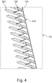
- Figur 4:
- eine schematische perspektivische Schnittansicht durch das Schutzgitter nach
Figur 3 .
- FIG. 1:
- a schematic front view of an embodiment of the extractor hood according to the invention;
- FIG. 2:
- a schematic sectional view of an embodiment of the invention with extractor hoods with currents;
- FIG. 3:
- a schematic perspective rear view of an embodiment of the protective grid; and
- FIG. 4:
- a schematic perspective sectional view through the protective grid according to
FIG. 3 ,
In
In der
In dem Dunstabzugsgehäuse 10 ist ein Gebläse 16 angeordnet. Das Gebläse 16 weist eine Lufteinlassöffnung 160, die eine kreisrunde Öffnung ist, und einen Luftauslasskanal 161 auf, der an dem Gehäuse des Gebläses 16 ausgebildet ist. Im Inneren des Gebläsegehäuses ist ein Lüfterrad (nicht sichtbar) angeordnet.In the
In dem Dunstabzugsgehäuse 10 ist eine Ansaugöffnung 14 gebildet, die zu der Absaugöffnung 17 des Wrasenschirms 11 nach hinten versetzt ist.In the
Auch in der Ausführungsform nach
Zu der Absaugöffnung 17 nach hinten versetzt ist vor der Ansaugöffnung 14 in dem Dunstabzugsgehäuse 10 ein Fettfilter 13 angeordnet. Hinter dem Fettfilter 13 und in der Ansaugöffnung 14 ist ein Schutzgitter 15 eingebracht. Der Fettfilter 13 kann beispielsweise dem Schutzgitter 15 verbunden, das heißt an diesem befestigt sein. Das Schutzgitter 15 ist an dem Dunstabzugsgehäuse 10 befestigt und weist eine Größe auf, die die Ansaugöffnung 14 vollständig abdeckt.Relocated to the
Das Gebläse 16 stellt ein Spiralgebläse dar. Das Gebläse 16 ist in dem Dunstabzugsgehäuse 10 angeordnet, dass die Lufteinlassöffnung 160 senkrecht zu dem Schutzgitter 15 steht. Das Gebläse 16 ist in horizontaler Richtung hinter der Ansaugöffnung in dem Dunstabzugsgehäuse 10 angeordnet.The
Das Schutzgitter 15 besteht aus einer Vielzahl von Luftleitelementen 150, deren Längserstreckung in der Horizontalen liegt. Die Luftleitelemente 150 weisen jeweils eine über deren Höhe gekrümmte Form auf. Als Höhe des Schutzgitters 15 wird die Abmessung des Schutzgitters 15 bezeichnet, die zu der Fläche des Schutzgitters 15 senkrecht steht. Insbesondere wird der senkrechte Abstand zwischen der der Eintrittsseite 153 und der Austrittsseite 154 des Schutzgitters 15 als Höhe bezeichnet.The
Der genauere Aufbau wird später unter Bezugnahme auf die
In der
Von dem Gebläse 16 wird über das darin vorgesehene Lüfterrad (nicht gezeigt) ein wirbelförmiger Sog gebildet. Die von dem Schutzgitter 15 angesaugte Luft ist aufgrund der Krümmung der Luftleitelemente 150 so ausgerichtet, dass diese tangential oder als Sekante an dem Sog auftrifft und damit einen Wirbel bildet. Die Luft wird nach dem Passieren des Lüfterrades durch den Luftauslasskanal 161 aus der Dunstabzugshaube 1 abgeführt.From the
In der in
In der
Wie sich aus
Mit der vorliegenden Erfindung wird somit eine Dunstabzugshaube geschaffen, bei der ein Schutzsystem durch ein Schutzgitter umgesetzt ist, welches verhindert, dass der Kunde rotierende Teile wie beispielsweise das Lüfterrad sowie stromführende Teile berührt. Dieses Schutzgitter, das auch als Eingriffsschutz bezeichnet werden kann, kann trotz Eingriff in die Luftführung der Dunstabzugshaube einen möglichst geringen oder keinerlei Verlust bei der Performance verursachen. Das heißt, dass bei der erfindungsgemäßen Dunstabzugshaube keine Einbußen bei Fördervolumen, Geräusch und Effizienz verursacht werden. Im Idealfall wird durch das Schutzgitter sogar eine verbesserte Performance erzielt. Des Weiteren sind Zusatzfunktionen wie die Filterhalterung oder Filteraufnahme beispielsweise von Fett- und/oder Umluftfiltern an dem Schutzgitter und eine Filterabdichtung möglich. In bevorzugten Ausführungsformen der Dunstabzugshaube wird zudem Reinigbarkeit verbessert sowie ein Sichtschutz durch das Schutzgitter geschaffen.With the present invention, therefore, an extractor hood is provided in which a protective system is implemented by a protective grid, which prevents the customer touches rotating parts such as the fan and live parts. This protective grille, which can also be referred to as anti-tampering, can cause as little or no loss in performance as possible, despite interference with the air duct of the extractor hood. This means that no losses in delivery volume, noise and efficiency are caused in the extractor hood according to the invention. Ideally, the guard will even achieve improved performance. Furthermore, additional functions such as the filter holder or filter holder, for example, of grease and / or circulating air filters on the protective grid and a filter seal are possible. In preferred embodiments of the hood also cleanability is improved and created a privacy through the guard.
Bei dem erfindungsgemäß Verwendeten Schutzgitter ist insbesondere die Form der Luftleitelemente, das heißt die Lamellenform von Bedeutung. Die Lamellen müssen mehrere Teile widersprüchliche Anforderungen erfüllen. Grundsätzlich müssen diese alle Sicherheitsanforderungen seitens VDE erfüllen, wodurch eine hohe Stabilität und feste Anbindung an das Gehäuse verlangt wird. Das Schutzgitter muss zudem verhindern, dass der Benutzer in das rotierende Lüfterrad beziehungsweise an spannungsführende Bauteile greift. Hierfür werden normalerweise ein hoher Materialeinsatz sowie geringe Abstände zwischen den Lamellen notwendig. Durch geringe Abstände zwischen den Lamellen sowie hohen Materialeinsatz, wird jedoch die Versperrfläche im Ansaugbereich erhöht, was zu einer Verschlechterung in den Performancewerten (Fördervolumen, Geräusch, Effizienz) führt. Mit der erfindungsgemäß verwendeten Form der Luftleitelemente, bei denen die Luftleitelemente, das heißt Lamellen gekrümmt sind, werden die bestmögliche Performancewerte bei größtmöglichem Versperreffekt geliefert. Zudem sind die Lamellen des Schutzgitters vorzugsweise so gestaltet, dass die Eigenschaften des Gebläses optimal unterstützt werden, das heißt die angesaugte Luft wird in einen Drall versetzt und gelangt verlustfrei in das Gebläse.In the case of the protective grid used according to the invention, the shape of the air-guiding elements, that is to say the lamella shape, is of importance in particular. The slats must meet several parts of conflicting requirements. Basically, these have to fulfill all safety requirements of VDE, which demands a high stability and fixed connection to the housing. The protective grid must also prevent the user from reaching into the rotating fan wheel or to live components. For this purpose, usually a high material usage and small distances between the slats are necessary. However, the small clearance between the blades and the high material usage increase the obstruction area in the intake area, which leads to a deterioration in the performance values (delivery volume, noise, efficiency). With the shape of the air guide elements used according to the invention, in which the air guide elements, that is to say slats, are curved, the best possible performance values are delivered with the greatest possible possible reversing effect. In addition, the fins of the protective grid are preferably designed so that the properties of the fan are optimally supported, that is, the sucked air is placed in a twist and passes lossless in the fan.
Trotz der hohen Anforderungen an die Stabilität kann das Schutzgitter vorzugsweise schraubenlos montieren werden. Dies wird beispielsweise über einen Schiebe-Rastverschluss umgesetzt, bei dem beispielsweise Schiebelaschen und/oder Rasthaken verwendet werden.Despite the high stability requirements, the protective grid can preferably be mounted without screws. This is implemented, for example, via a sliding latching closure, in which, for example, sliding lugs and / or latching hooks are used.
Ein guter Sichtschutz in die Dunstabzugshaube kann zudem durch das Schutzgitter geliefert werden und steigert die optische Anmutung der Dunstabzugshaube. Dabei werden unter anderem Kabel so verdeckt werden, dass diese von außen nicht sichtbar sind. Diese Anforderung steht wieder im Widerspruch zu der Versperrfläche und wurde unter Berücksichtigung der zu erzielenden Performancewerte umgesetzt.A good privacy in the cooker hood can also be supplied through the protective grille and enhances the visual appearance of the cooker hood. Among other things, cables will be covered so that they are not visible from the outside. This requirement is again in conflict with the barrier area and has been implemented taking into account the performance values to be achieved.
Um eine sehr gute Reinigbarkeit "EasyClean" zu erzielen, werden zudem Verstärkungsstreben des Schutzgitters, die auch als Vertikalverstrebungen der Lamellen bezeichnet werden, soweit wie möglich nach hinten versetzt, so dass der Benutzer die vorzugsweise horizontalen Lamellen gut säubern kann. Die Vertikalverstrebung ist notwendig, um eine hohe Steifigkeit zu erzielen, damit der Benutzer nicht zwischen den Lamellen durchgreifen kann. Beim Auswischen des Schutzgitters kann direkt von einer Seite zur anderen durchgewischt werden, ohne, dass man mit den Lappen an den Vertikalverstrebungen hängen bleibt.In order to achieve a very good cleanability "EasyClean", also reinforcing struts of the protective grid, which are also referred to as vertical struts of the slats, as far as possible offset to the rear, so that the user can clean the preferably horizontal slats well. The vertical bracing is necessary in order to achieve a high rigidity, so that the user does not reach through between the slats can. When wiping the protective grille, it is possible to wipe directly from one side to the other without getting caught in the vertical braces with the rags.
Die Erfindung weist somit eine Reihe von Vorteilen auf. Zum einen wird der Benutzer vor mechanischen und elektrischen Gefahren geschützt. Eine einfache Reinigung des Schutzgitters ist möglich. Ebenso kann die Montage des Schutzgitters schraublos erfolgen. Weiterhin wird eine Performanceverbesserung durch die Geometrie der Luftleitelemente, die auch als Leitgeometrie bezeichnet werden kann, erzielt und dabei beispielsweise das Fördervolumen und Effizienz beibehalten oder verbessert und die Geräuschentwicklung minimiert. Schließlich kann vorzugsweise der Innenraum der Dunstabzugshaube nicht zugänglich sein, so dass das Schutzgitter auch als Sichtschutz für den Innenraum dient.The invention thus has a number of advantages. On the one hand, the user is protected against mechanical and electrical hazards. Simple cleaning of the protective grid is possible. Likewise, the mounting of the protective grille can be screwless. Furthermore, a performance improvement by the geometry of the air guide elements, which can also be referred to as Leitgeometrie achieved, while maintaining or improving the delivery volume and efficiency and minimizes noise, for example. Finally, the interior of the extractor hood preferably can not be accessible, so that the protective grid also serves as a privacy screen for the interior.
- 11
- DunstabzugshaubeHood
- 1010
- DunstabzugsgehäuseExtractor housing
- 100100
- Rasthakenlatch hook
- 101101
- Schiebehakensliding hooks
- 1111
- Wrasenschirmcanopy
- 1212
- Prallplatteflapper
- 1313
- Filterfilter
- 1414
- Ansaugöffnungsuction
- 1515
- Schutzgitterguard
- 150150
- Lamellelamella
- 151151
- Verstärkungsstrebereinforcing strut
- 153153
- Eintrittsseiteentry page
- 154154
- Austrittsseiteexit side
- 1616
- Gebläsefan
- 160160
- LufteinlassöffnungAir inlet opening
- 161161
- Luftauslasskanalair outlet
- 1717
- Absaugöffnungsuction
Claims (10)
Applications Claiming Priority (1)
| Application Number | Priority Date | Filing Date | Title |
|---|---|---|---|
| DE102016205373.6A DE102016205373A1 (en) | 2016-03-31 | 2016-03-31 | Hood |
Publications (1)
| Publication Number | Publication Date |
|---|---|
| EP3225920A1 true EP3225920A1 (en) | 2017-10-04 |
Family
ID=58185425
Family Applications (1)
| Application Number | Title | Priority Date | Filing Date |
|---|---|---|---|
| EP17158174.7A Withdrawn EP3225920A1 (en) | 2016-03-31 | 2017-02-27 | Extractor hood |
Country Status (2)
| Country | Link |
|---|---|
| EP (1) | EP3225920A1 (en) |
| DE (1) | DE102016205373A1 (en) |
Cited By (4)
| Publication number | Priority date | Publication date | Assignee | Title |
|---|---|---|---|---|
| CN108613233A (en) * | 2018-06-08 | 2018-10-02 | 天津大学 | A kind of rotation fiber leaf fat fume purifying apparatus |
| CN109631114A (en) * | 2018-12-31 | 2019-04-16 | 佛山市云米电器科技有限公司 | A kind of smoke machine shell of adjustable air inlet angle |
| DE202019103290U1 (en) | 2019-06-12 | 2019-06-18 | BSH Hausgeräte GmbH | Extractor hood with protection element |
| EP4180725A1 (en) * | 2021-11-10 | 2023-05-17 | Berbel Ablufttechnik GmbH | Extractor hood |
Citations (4)
| Publication number | Priority date | Publication date | Assignee | Title |
|---|---|---|---|---|
| JPS6423047A (en) * | 1987-07-17 | 1989-01-25 | Daiichi Home Kk | Exhaust suction opening for forced ventilating device for cooking |
| JPH03207925A (en) * | 1990-01-08 | 1991-09-11 | Matsushita Electric Ind Co Ltd | Waste gas exhausting device |
| DE10052233A1 (en) * | 2000-10-21 | 2002-05-02 | Max Homeier | Extractor hood for cookers consists of convex hollow plate for optimum aerodynamic movement of rising vapors |
| DE102007021318A1 (en) | 2007-05-07 | 2008-11-13 | BSH Bosch und Siemens Hausgeräte GmbH | Extractor hood and extractor hood |
-
2016
- 2016-03-31 DE DE102016205373.6A patent/DE102016205373A1/en not_active Ceased
-
2017
- 2017-02-27 EP EP17158174.7A patent/EP3225920A1/en not_active Withdrawn
Patent Citations (4)
| Publication number | Priority date | Publication date | Assignee | Title |
|---|---|---|---|---|
| JPS6423047A (en) * | 1987-07-17 | 1989-01-25 | Daiichi Home Kk | Exhaust suction opening for forced ventilating device for cooking |
| JPH03207925A (en) * | 1990-01-08 | 1991-09-11 | Matsushita Electric Ind Co Ltd | Waste gas exhausting device |
| DE10052233A1 (en) * | 2000-10-21 | 2002-05-02 | Max Homeier | Extractor hood for cookers consists of convex hollow plate for optimum aerodynamic movement of rising vapors |
| DE102007021318A1 (en) | 2007-05-07 | 2008-11-13 | BSH Bosch und Siemens Hausgeräte GmbH | Extractor hood and extractor hood |
Cited By (5)
| Publication number | Priority date | Publication date | Assignee | Title |
|---|---|---|---|---|
| CN108613233A (en) * | 2018-06-08 | 2018-10-02 | 天津大学 | A kind of rotation fiber leaf fat fume purifying apparatus |
| CN108613233B (en) * | 2018-06-08 | 2024-03-22 | 天津大学 | Rotatory fibreboard oil smoke purifier |
| CN109631114A (en) * | 2018-12-31 | 2019-04-16 | 佛山市云米电器科技有限公司 | A kind of smoke machine shell of adjustable air inlet angle |
| DE202019103290U1 (en) | 2019-06-12 | 2019-06-18 | BSH Hausgeräte GmbH | Extractor hood with protection element |
| EP4180725A1 (en) * | 2021-11-10 | 2023-05-17 | Berbel Ablufttechnik GmbH | Extractor hood |
Also Published As
| Publication number | Publication date |
|---|---|
| DE102016205373A1 (en) | 2017-10-05 |
Similar Documents
| Publication | Publication Date | Title |
|---|---|---|
| EP3225920A1 (en) | Extractor hood | |
| DE19753373A1 (en) | Housing for axial cooling fan for EMC-screened apparatus, such as CPU | |
| EP0118570B1 (en) | Extracting hood with air circulation | |
| DE69711361T2 (en) | microwave oven | |
| EP2397775A2 (en) | Extraction device | |
| EP3232127B1 (en) | Extractor hood with outlet grid | |
| DE102017216456A1 (en) | Ventilation device for hob and hob with ventilation device | |
| EP2137463A2 (en) | Extractor hood | |
| DE3120569A1 (en) | Kitchen vapour extractor hood | |
| DE19964489B4 (en) | Induction hob with cooling fan | |
| DE102008053145A1 (en) | Flow guiding device for a cooking appliance | |
| EP0726424A2 (en) | Smoke extracting hood | |
| DE102016204819A1 (en) | Extractor hood with viewing hood and interior element | |
| WO2011047944A1 (en) | Filter element for an oven | |
| DE102019109401B4 (en) | Fan device for sucking in and discharging vapours underneath a hob and hob | |
| DE102017131168A1 (en) | Extractor hood with round inflow area in inclined guide surface | |
| EP2629024B1 (en) | Extractor with improved suction intake | |
| DE202019103290U1 (en) | Extractor hood with protection element | |
| DE102017123759A1 (en) | "Blow-out" | |
| DE112019006755T5 (en) | Outdoor unit for air conditioning | |
| DE102018205556A1 (en) | Kitchen arrangement and method for operating a kitchen arrangement | |
| DE2407796A1 (en) | Ventilator with centrifugal fan inside spiral housing - has air deflection baffles guiding air through two side vents | |
| DE102019220295A1 (en) | Creation of an air curtain to improve the extraction of vapor with extractor hoods | |
| DE102017210758A1 (en) | fan | |
| DE102014108252A1 (en) | filtering device |
Legal Events
| Date | Code | Title | Description |
|---|---|---|---|
| PUAI | Public reference made under article 153(3) epc to a published international application that has entered the european phase |
Free format text: ORIGINAL CODE: 0009012 |
|
| STAA | Information on the status of an ep patent application or granted ep patent |
Free format text: STATUS: THE APPLICATION HAS BEEN PUBLISHED |
|
| AK | Designated contracting states |
Kind code of ref document: A1 Designated state(s): AL AT BE BG CH CY CZ DE DK EE ES FI FR GB GR HR HU IE IS IT LI LT LU LV MC MK MT NL NO PL PT RO RS SE SI SK SM TR |
|
| AX | Request for extension of the european patent |
Extension state: BA ME |
|
| STAA | Information on the status of an ep patent application or granted ep patent |
Free format text: STATUS: REQUEST FOR EXAMINATION WAS MADE |
|
| 17P | Request for examination filed |
Effective date: 20180404 |
|
| RBV | Designated contracting states (corrected) |
Designated state(s): AL AT BE BG CH CY CZ DE DK EE ES FI FR GB GR HR HU IE IS IT LI LT LU LV MC MK MT NL NO PL PT RO RS SE SI SK SM TR |
|
| STAA | Information on the status of an ep patent application or granted ep patent |
Free format text: STATUS: EXAMINATION IS IN PROGRESS |
|
| 17Q | First examination report despatched |
Effective date: 20191025 |
|
| STAA | Information on the status of an ep patent application or granted ep patent |
Free format text: STATUS: EXAMINATION IS IN PROGRESS |
|
| GRAP | Despatch of communication of intention to grant a patent |
Free format text: ORIGINAL CODE: EPIDOSNIGR1 |
|
| STAA | Information on the status of an ep patent application or granted ep patent |
Free format text: STATUS: GRANT OF PATENT IS INTENDED |
|
| INTG | Intention to grant announced |
Effective date: 20210419 |
|
| STAA | Information on the status of an ep patent application or granted ep patent |
Free format text: STATUS: THE APPLICATION IS DEEMED TO BE WITHDRAWN |
|
| 18D | Application deemed to be withdrawn |
Effective date: 20210831 |