EP3224507B1 - Dichtelement und verfahren zum herstellen eines dichtelements - Google Patents
Dichtelement und verfahren zum herstellen eines dichtelements Download PDFInfo
- Publication number
- EP3224507B1 EP3224507B1 EP15802071.9A EP15802071A EP3224507B1 EP 3224507 B1 EP3224507 B1 EP 3224507B1 EP 15802071 A EP15802071 A EP 15802071A EP 3224507 B1 EP3224507 B1 EP 3224507B1
- Authority
- EP
- European Patent Office
- Prior art keywords
- approximately
- sealing element
- sealing
- thermoplastic material
- main body
- Prior art date
- Legal status (The legal status is an assumption and is not a legal conclusion. Google has not performed a legal analysis and makes no representation as to the accuracy of the status listed.)
- Active
Links
Images





Classifications
-
- F—MECHANICAL ENGINEERING; LIGHTING; HEATING; WEAPONS; BLASTING
- F16—ENGINEERING ELEMENTS AND UNITS; GENERAL MEASURES FOR PRODUCING AND MAINTAINING EFFECTIVE FUNCTIONING OF MACHINES OR INSTALLATIONS; THERMAL INSULATION IN GENERAL
- F16J—PISTONS; CYLINDERS; SEALINGS
- F16J15/00—Sealings
- F16J15/16—Sealings between relatively-moving surfaces
- F16J15/32—Sealings between relatively-moving surfaces with elastic sealings, e.g. O-rings
- F16J15/3284—Sealings between relatively-moving surfaces with elastic sealings, e.g. O-rings characterised by their structure; Selection of materials
-
- B—PERFORMING OPERATIONS; TRANSPORTING
- B29—WORKING OF PLASTICS; WORKING OF SUBSTANCES IN A PLASTIC STATE IN GENERAL
- B29C—SHAPING OR JOINING OF PLASTICS; SHAPING OF MATERIAL IN A PLASTIC STATE, NOT OTHERWISE PROVIDED FOR; AFTER-TREATMENT OF THE SHAPED PRODUCTS, e.g. REPAIRING
- B29C45/00—Injection moulding, i.e. forcing the required volume of moulding material through a nozzle into a closed mould; Apparatus therefor
- B29C45/0053—Injection moulding, i.e. forcing the required volume of moulding material through a nozzle into a closed mould; Apparatus therefor combined with a final operation, e.g. shaping
- B29C45/0055—Shaping
-
- B—PERFORMING OPERATIONS; TRANSPORTING
- B29—WORKING OF PLASTICS; WORKING OF SUBSTANCES IN A PLASTIC STATE IN GENERAL
- B29C—SHAPING OR JOINING OF PLASTICS; SHAPING OF MATERIAL IN A PLASTIC STATE, NOT OTHERWISE PROVIDED FOR; AFTER-TREATMENT OF THE SHAPED PRODUCTS, e.g. REPAIRING
- B29C45/00—Injection moulding, i.e. forcing the required volume of moulding material through a nozzle into a closed mould; Apparatus therefor
- B29C45/17—Component parts, details or accessories; Auxiliary operations
- B29C45/26—Moulds
- B29C45/37—Mould cavity walls, i.e. the inner surface forming the mould cavity, e.g. linings
-
- F—MECHANICAL ENGINEERING; LIGHTING; HEATING; WEAPONS; BLASTING
- F16—ENGINEERING ELEMENTS AND UNITS; GENERAL MEASURES FOR PRODUCING AND MAINTAINING EFFECTIVE FUNCTIONING OF MACHINES OR INSTALLATIONS; THERMAL INSULATION IN GENERAL
- F16J—PISTONS; CYLINDERS; SEALINGS
- F16J15/00—Sealings
- F16J15/16—Sealings between relatively-moving surfaces
- F16J15/32—Sealings between relatively-moving surfaces with elastic sealings, e.g. O-rings
-
- F—MECHANICAL ENGINEERING; LIGHTING; HEATING; WEAPONS; BLASTING
- F16—ENGINEERING ELEMENTS AND UNITS; GENERAL MEASURES FOR PRODUCING AND MAINTAINING EFFECTIVE FUNCTIONING OF MACHINES OR INSTALLATIONS; THERMAL INSULATION IN GENERAL
- F16J—PISTONS; CYLINDERS; SEALINGS
- F16J15/00—Sealings
- F16J15/16—Sealings between relatively-moving surfaces
- F16J15/32—Sealings between relatively-moving surfaces with elastic sealings, e.g. O-rings
- F16J15/3204—Sealings between relatively-moving surfaces with elastic sealings, e.g. O-rings with at least one lip
- F16J15/3208—Sealings between relatively-moving surfaces with elastic sealings, e.g. O-rings with at least one lip provided with tension elements, e.g. elastic rings
- F16J15/3212—Sealings between relatively-moving surfaces with elastic sealings, e.g. O-rings with at least one lip provided with tension elements, e.g. elastic rings with metal springs
-
- F—MECHANICAL ENGINEERING; LIGHTING; HEATING; WEAPONS; BLASTING
- F16—ENGINEERING ELEMENTS AND UNITS; GENERAL MEASURES FOR PRODUCING AND MAINTAINING EFFECTIVE FUNCTIONING OF MACHINES OR INSTALLATIONS; THERMAL INSULATION IN GENERAL
- F16J—PISTONS; CYLINDERS; SEALINGS
- F16J15/00—Sealings
- F16J15/16—Sealings between relatively-moving surfaces
- F16J15/32—Sealings between relatively-moving surfaces with elastic sealings, e.g. O-rings
- F16J15/3204—Sealings between relatively-moving surfaces with elastic sealings, e.g. O-rings with at least one lip
- F16J15/3232—Sealings between relatively-moving surfaces with elastic sealings, e.g. O-rings with at least one lip having two or more lips
- F16J15/3236—Sealings between relatively-moving surfaces with elastic sealings, e.g. O-rings with at least one lip having two or more lips with at least one lip for each surface, e.g. U-cup packings
-
- F—MECHANICAL ENGINEERING; LIGHTING; HEATING; WEAPONS; BLASTING
- F16—ENGINEERING ELEMENTS AND UNITS; GENERAL MEASURES FOR PRODUCING AND MAINTAINING EFFECTIVE FUNCTIONING OF MACHINES OR INSTALLATIONS; THERMAL INSULATION IN GENERAL
- F16J—PISTONS; CYLINDERS; SEALINGS
- F16J15/00—Sealings
- F16J15/16—Sealings between relatively-moving surfaces
- F16J15/32—Sealings between relatively-moving surfaces with elastic sealings, e.g. O-rings
- F16J15/328—Manufacturing methods specially adapted for elastic sealings
-
- F—MECHANICAL ENGINEERING; LIGHTING; HEATING; WEAPONS; BLASTING
- F16—ENGINEERING ELEMENTS AND UNITS; GENERAL MEASURES FOR PRODUCING AND MAINTAINING EFFECTIVE FUNCTIONING OF MACHINES OR INSTALLATIONS; THERMAL INSULATION IN GENERAL
- F16J—PISTONS; CYLINDERS; SEALINGS
- F16J15/00—Sealings
- F16J15/56—Other sealings for reciprocating rods
-
- F—MECHANICAL ENGINEERING; LIGHTING; HEATING; WEAPONS; BLASTING
- F16—ENGINEERING ELEMENTS AND UNITS; GENERAL MEASURES FOR PRODUCING AND MAINTAINING EFFECTIVE FUNCTIONING OF MACHINES OR INSTALLATIONS; THERMAL INSULATION IN GENERAL
- F16L—PIPES; JOINTS OR FITTINGS FOR PIPES; SUPPORTS FOR PIPES, CABLES OR PROTECTIVE TUBING; MEANS FOR THERMAL INSULATION IN GENERAL
- F16L11/00—Hoses, i.e. flexible pipes
- F16L11/04—Hoses, i.e. flexible pipes made of rubber or flexible plastics
- F16L11/12—Hoses, i.e. flexible pipes made of rubber or flexible plastics with arrangements for particular purposes, e.g. specially profiled, with protecting layer, heated, electrically conducting
- F16L11/121—Hoses, i.e. flexible pipes made of rubber or flexible plastics with arrangements for particular purposes, e.g. specially profiled, with protecting layer, heated, electrically conducting specially profiled cross sections
-
- F—MECHANICAL ENGINEERING; LIGHTING; HEATING; WEAPONS; BLASTING
- F16—ENGINEERING ELEMENTS AND UNITS; GENERAL MEASURES FOR PRODUCING AND MAINTAINING EFFECTIVE FUNCTIONING OF MACHINES OR INSTALLATIONS; THERMAL INSULATION IN GENERAL
- F16L—PIPES; JOINTS OR FITTINGS FOR PIPES; SUPPORTS FOR PIPES, CABLES OR PROTECTIVE TUBING; MEANS FOR THERMAL INSULATION IN GENERAL
- F16L33/00—Arrangements for connecting hoses to rigid members; Rigid hose-connectors, i.e. single members engaging both hoses
- F16L33/30—Arrangements for connecting hoses to rigid members; Rigid hose-connectors, i.e. single members engaging both hoses comprising parts inside the hoses only
-
- B—PERFORMING OPERATIONS; TRANSPORTING
- B29—WORKING OF PLASTICS; WORKING OF SUBSTANCES IN A PLASTIC STATE IN GENERAL
- B29C—SHAPING OR JOINING OF PLASTICS; SHAPING OF MATERIAL IN A PLASTIC STATE, NOT OTHERWISE PROVIDED FOR; AFTER-TREATMENT OF THE SHAPED PRODUCTS, e.g. REPAIRING
- B29C45/00—Injection moulding, i.e. forcing the required volume of moulding material through a nozzle into a closed mould; Apparatus therefor
- B29C45/0001—Injection moulding, i.e. forcing the required volume of moulding material through a nozzle into a closed mould; Apparatus therefor characterised by the choice of material
-
- F—MECHANICAL ENGINEERING; LIGHTING; HEATING; WEAPONS; BLASTING
- F16—ENGINEERING ELEMENTS AND UNITS; GENERAL MEASURES FOR PRODUCING AND MAINTAINING EFFECTIVE FUNCTIONING OF MACHINES OR INSTALLATIONS; THERMAL INSULATION IN GENERAL
- F16J—PISTONS; CYLINDERS; SEALINGS
- F16J15/00—Sealings
- F16J15/16—Sealings between relatively-moving surfaces
- F16J15/32—Sealings between relatively-moving surfaces with elastic sealings, e.g. O-rings
- F16J15/3204—Sealings between relatively-moving surfaces with elastic sealings, e.g. O-rings with at least one lip
- F16J15/3208—Sealings between relatively-moving surfaces with elastic sealings, e.g. O-rings with at least one lip provided with tension elements, e.g. elastic rings
Definitions
- the present invention relates to a sealing element, in particular for use as a rod seal, piston seal and / or shaft seal.
- Such a sealing element is for example from DE 10 2012 112 594 A1 , of the EP 2 559 922 A1 , of the WO 2007/033072 A2 , of the DE 10 2007 063 216 A1 as well as the US 6,557,857 B1 known.
- the present invention is based on the object of providing a sealing element which ensures a reliable seal and can be produced simply and inexpensively.
- the base body is an injection-moldable, thermoplastic plastic material or is formed from an injection-moldable, thermoplastic plastic material.
- thermoplastic plastic material is a fluorothermoplastic material, for example a fully fluorinated thermoplastic plastic material.
- the present invention also relates to a method for producing a sealing element.
- the invention is based on the object of providing a method by means of which a reliably sealing sealing element can be produced simply and inexpensively.
- this object is achieved by a method according to the independent method claim.
- the base body is made from injection-moldable, partially fluorinated or fully fluorinated thermoplastic material.
- thermoplastic plastic material can preferably be produced or produced as follows: It can be favorable if the thermoplastic plastic material is a compound material which can be produced or produced in particular by means of a compounding system.
- the compounding plant preferably comprises an extruder, in particular a screw extruder, for example a twin-screw extruder.
- a mixing ratio of the starting materials and a temperature profile must be precisely controlled and / or regulated.
- thermoplastic material For the production of the thermoplastic material, one or more of the following processing conditions, in particular all of the following processing conditions, are preferably observed: parameter unit value Raw material 1 - fluoropolymer % 94 Raw material 2 - carbon fiber % 4th Raw material 3 - graphite % 2 Screw diameter mm 25th Ratio of length to diameter - 42 Temperatures in the successive zones of the plasticizing unit: C1 ° C 80 ⁇ 20 C2 ° C 340 ⁇ 20 C3 ° C 360 ⁇ 20 C4 ° C 365 ⁇ 20 C5 ° C 350 ⁇ 20 C6 ° C 340 ⁇ 20 Screw speed RPM 180 ⁇ 40 Mass pressure bar 12 ⁇ 6 Melt temperature (temperature at the outlet of the extruder) ° C 360 ⁇ 20 Mass flow rate kg / h 15 ⁇ 5 Take-off speed m / min 15 ⁇ 5
- the material "carbon fiber” is in particular carbon fiber.
- thermoplastic synthetic material is at least approximately 90%, for example approximately 94%, with regard to its mass and / or its volume.
- the fluoropolymer content of the thermoplastic synthetic material is at most approximately 99%, preferably at most approximately 96%, for example approximately 94%, with regard to its mass and / or its volume.
- thermoplastic synthetic material is at least approximately 0.5%, preferably at least approximately 2%, for example approximately 4%, in terms of its mass and / or its volume.
- a carbon fiber content of the thermoplastic plastic material is at most approximately 10%, preferably at most approximately 6%, for example approximately 4%, with regard to its mass and / or its volume.
- thermoplastic synthetic material is at least approximately 0.5%, preferably at least approximately 1.5%, for example approximately 2%, with regard to its mass and / or its volume.
- a graphite proportion of the thermoplastic plastic material is at most approximately 6%, preferably at most approximately 4%, for example approximately 2%, with regard to its mass and / or its volume.
- thermoplastic synthetic material obtained in the manner described is preferably used to produce one or more sealing elements.
- thermoplastic plastic material is preferably further processed, in particular in an injection molding process, in compliance with one or more of the following processing conditions, in particular all of the following processing conditions: parameter unit value Material designation - VM3050 Screw diameter mm 25th Temperatures in the successive zones of the plasticizing unit: C1 ° C 350 ⁇ 20 C2 ° C 365 ⁇ 20 C3 ° C 370 ⁇ 20 C4 ° C 375 ⁇ 20 C5 ° C 380 ⁇ 20 Mold temperature ° C 245 ⁇ 20 Plasticizing volume cm 3 15.6 Injection speed cm 3 / s 30th Injection pressure bar 1200 ⁇ 100 Emphasis bar 160 Hold time s 6th Remaining cooling time s 15th
- thermoplastic material referred to here as VM3050
- VM3050 when it is used to manufacture sealing elements, are shown in the following table in comparison with other materials: properties Specimen PTFE compound VM3050 VM3044 VM3006 processing - Pressing, sintering Thermoplastic (e.g. injection molding) Thermoplastic (e.g. injection molding) Thermoplastic (e.g.
- a sealing element designated as a whole by 100 is, for example, part of a high-pressure pump 102 and serves to seal between two media spaces 104 in the area of a movable component 106.
- the movable component 106 can be, for example, a piston of the high pressure pump 102.
- the movable component 106 is in particular passed through the sealing element 100.
- Both the movable component 106 and the sealing element 100 are preferably designed to be rotationally symmetrical about an axis of symmetry 108.
- the axis of symmetry 108 is aligned in particular parallel to a longitudinal axis 110 of the movable component 106 and of the sealing element 100.
- the sealing element 100 and the movable component 106 have a common axis of symmetry 108 in the assembled state.
- the longitudinal axis 110 preferably defines an axial direction 112.
- a direction oriented perpendicular to the axial direction 112 is a radial direction 114.
- the media spaces 104 are preferably separated from one another in the axial direction 112 by means of the sealing element 100.
- the sealing element 100 preferably adjoins the movable component 106, directed inwardly in the radial direction 114, by means of two dynamic sealing sections 116.
- the sealing element 100 adjoins a housing 118 of the high-pressure pump 102.
- the sealing element 100 is fixed relative to the housing 118.
- Two sealing areas 120 of the sealing element 100 assigned to the two media spaces 104 thus also comprise two static sealing sections 122 resting on the housing 118 in addition to the dynamic sealing sections 116.
- the dynamic sealing sections 116 are used for dynamic sealing between the sealing element 100 and the component 106 that moves relative to the sealing element 100, in particular that is displaceable along the axial direction 112.
- One or more spring elements 124 of the sealing element 100 can be provided in order to achieve an increased sealing effect.
- the one or more spring elements 124 can, in particular, be arranged or arranged in one or more spring element receptacles 126.
- One or more dynamic sealing sections 116 can be pressed onto the movable component 106 by means of the one or more spring elements 124.
- one or more static sealing sections 122 can be pressed against a housing 118 of the high-pressure pump 102 by means of the one or more spring elements 124.
- a spring element 124 is in particular ring-shaped, for example circular ring-shaped, and has, for example, a V-shaped or U-shaped cross section.
- Each dynamic sealing section 116 preferably comprises a sealing lip 127 each with one, two or more than two sealing edges 128.
- Each sealing lip 127 and / or each sealing edge 128 is preferably essentially annular and essentially rotationally symmetrical about the axis of symmetry 108.
- each sealing lip 127 is preferably arranged at different distances from a transverse center plane 130 of the sealing element 100 that extends perpendicular to the longitudinal axis 110 of the sealing element 100.
- the sealing element 100 comprises in particular a base body 132, which is preferably formed in one piece from a thermoplastic material.
- the base body 132 comprises in particular one or more dynamic sealing sections 116, one or more static sealing sections 122 and one or more spring element receptacles 126.
- the base body 132 can be produced, for example, as follows: For example, a blank 134 of the base body 132 can be produced in an injection molding process.
- the blank 134 of the base body 132 only has its final outer shape in sections.
- the sealing sections 116, 122 have to be reworked in order to complete the base body 132, in particular by machining, for example CNC machining.
- an outer contour can be machined for example first in order to complete the radially outer static sealing sections 122. Subsequently, a radially inner machining can then take place in order to complete the dynamic sealing sections 116.
- the blank 134 is produced, for example, in an injection molding process in such a way that both the static sealing sections 122 and the spring element receptacles 126 already have the final external shape after the injection molding process has been carried out.
- a sealing lip 127 of a dynamic sealing section 116 of an alternative embodiment of a sealing element 100 is shown.
- the sealing lip 127 of this sealing element 100 differs from the sealing lip 127 in FIG Fig. 3 illustrated embodiment of the sealing element 100 essentially by its geometry.
- the sealing lip 127 is formed by a section of the basic body 132 that runs slightly obliquely to the axial direction 112 and projects slightly inward in the radial direction 114 from a central section 140 of the basic body 132.
- the sealing lip 127 includes a movable component 106 in the assembled state of the sealing element 100 facing bottom 142 as well as a top 144 facing away from movable component 106 in the assembled state of sealing element 100.
- the top 144 is essentially flat in cross section.
- the upper side 144 has, in particular, the shape of a truncated cone.
- One or more, for example two, projections 146 are provided on the underside 142 of the sealing lip 127.
- projections 146 form the sealing edges 128 of the sealing lip 127 at their ends protruding inward in the radial direction 114.
- the sealing edges 128 are each adjoined by a flank 148.
- a recess 150 or indentation 152 of the sealing lip 127 is provided on a side of each flank 148 facing away from the respective sealing edge 128.
- a recess 150 is provided between the two projections 146 forming the sealing edge 128.
- a further recess 150 is preferably formed between the sealing edge 128i, which is inner in the axial direction 112, and the central section 140 of the base body 132.
- the middle section 140 of the base body 132 can comprise a guide section 154.
- This guide section 154 preferably has a surface running parallel to the axis of symmetry 108 and is used to support and / or guide the movable component 106 in the event of a sideways movement of the movable component 106 when the sealing element 100 is in use.
- a distance between the guide section 154 and the axis of symmetry 108 is preferably greater than a radius R B of the movable component 106.
- the outer sealing edge 128a of the sealing lip 127 forms a primary sealing edge 128.
- the inner sealing edge 128i of the sealing lip 127 forms a secondary sealing edge 128.
- the outer sealing edge 128a and the recess 150 adjoining this outer sealing edge 128a in the axial direction 112 inwardly have an axial distance A aa from one another which, for example, is at least approximately an axial distance A ai between the inner sealing edge 128i and which corresponds to this inner sealing edge 128i in the axial direction 112 inwardly adjoining recess 150.
- the distance A aa is preferably between approximately 0.5 mm to approximately 2.5 mm, for example between approximately 0.5 mm to approximately 1.5 mm, in particular between approximately 0.6 mm to approximately 1 mm.
- Both the distance A aa and the distance A ai are preferably based on the distance between the relevant points of the sealing lip 127 from one another in the axial direction 112.
- the sealing element 100 can be demolded from a molding device (not shown), for example when it is manufactured in an injection molding process, with as little damage as possible.
- the sealing lip 127 can be bent outward in the radial direction 114 during removal from the mold in the area of the outer sealing edge 128a in order to also enable the projection 146 forming the inner sealing edge 128i to be removed from the mold as non-destructively as possible.
- the outer sealing edge 128a and the inner sealing edge 128i are preferably moved essentially uniformly outward in the radial direction 114.
- the forces acting on the sealing lip 127 as a result can then preferably be transmitted and absorbed evenly.
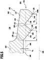
- FIG. 5 The illustrated alternative embodiment of a sealing lip 127 of a sealing element 100 differs from that in FIG Fig. 4 The embodiment shown essentially in that the middle section 140 does not have a guide section 154.
- a distance A m between the middle section 140 and the movable component 106 in the assembled state of the sealing element 100 is consequently greater than in the case of FIG Fig. 4 illustrated embodiment of the sealing element 100.
- radii R of the sealing edges 128 and the depressions 150 are shown.
- the choice of suitable radii influences in particular demolding of the sealing element 100 after it has been manufactured in an injection molding process.
- the radii R of the sealing edges 128 and of the recesses 150 are preferably selected to be at least approximately similar.
- the radii are between approximately 0.1 mm and approximately 0.5 mm, in particular approximately 0.2 mm.
- the radii R of the sealing edges 128 can be larger or smaller than the radii R of the recesses 150.
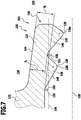
- the sealing lip 127 is preferably designed such that a sealing lip thickness D 1 in the area of the recess 150 or indentation 152 between the central section 140 and the flank 148 of the inner sealing edge 128i is greater than a sealing lip thickness D 2 between the two sealing edges 128i, 128a in the area of the recess 150 or indentation 152 arranged in between.
- the sealing lip thickness D 1 , D 2 is in each case a minimum distance between the upper side 144 of the sealing lip 127 and the respective depression 150 or indentation 152.
- the sealing lip thickness D 1 is, for example, between approximately 0.4 mm to approximately 1 mm, in particular between approximately 0.5 mm to approximately 0.7 mm, preferably approximately 0.6 mm.
- the sealing lip thickness D 2 is between approximately 0.3 mm to approximately 0.7 mm, in particular approximately 0.5 mm.
- the sealing lip 127 is designed in particular in such a way that an optimal seal on the movable component 106 is ensured when this movable component 106 has a radius R B between approximately 2 mm to 9 mm, in particular approximately 2.5 mm to approximately 6.5 mm.
- the sealing lip 127 projects obliquely to the axial direction 112 and obliquely to the radial direction 114 away from the central section 140 of the base body 132 of the sealing element 100.
- a sealing lip angle ⁇ which is enclosed on the one hand by the top 144 of the sealing lip 127 and on the other hand by the axis of symmetry 108, is preferably between approximately 3 ° and approximately 10 ° in the completed state of the base body 132 before a spring element 124 is installed.
- the sealing lip angle ⁇ can be larger, for example by approximately 1 ° to 3 °.
- the sealing lip angle ⁇ is initially selected to be smaller when the base body 132 is manufactured.
- a sealing lip angle ⁇ of 0 ° can initially be provided.
- the top 144 of the sealing lip 127 then runs essentially parallel to the axis of symmetry 108.
- post-processing or post-treatment of the base body 132 is then preferably carried out after the production of the base body 132 in the injection molding process.
- the sealing lip 127 is reshaped by cold forming or deformation after or during heating of the sealing lip 127 and / or the entire base body 132, in particular in order to obtain a sealing lip angle ⁇ of more than approximately 3 °.
- undercut depths T are shown which, due to the geometry of the sealing lip 127, are overcome when the sealing element 100 is removed from the mold Need to become.
- An undercut depth T between the two sealing edges 128 is preferably less than an undercut depth T in the region of the central section 140 of the base body 132 and / or than in the region of a recess 150 and / of the indentation arranged between the central section 140 and the flank 148 of the inner sealing edge 128i 152.
- the removal of the sealing element 100 from an injection molding tool is in particular a forced removal.
- the sealing lip 127 preferably has a depot 156 for receiving a medium, for example fuel or engine oil.
- a leakage of the sealing element in the area of the sealing lip 127 can be compensated for at least temporarily by means of the depot 156, in that the medium guided past the outer sealing edge 128a is received in the depot 156.
- the received medium can gradually be conveyed back into the adjoining media space 104.
- a depot depth T D is preferably a minimum distance between the recess 150 between the two sealing edges 128 and a straight line running through the two sealing edges 128.
- the depot depth T D is preferably between approximately 0.1 mm to approximately 0.4 mm, in particular between approximately 0.15 mm and approximately 0.25 mm.
- the described parameters of a sealing lip 127 preferably apply to a sealing lip 127 of a dynamic sealing section 116 of the sealing element 100. It can also be provided that the The values and parameters described apply to both sealing lips 127 of both dynamic sealing sections 116.
- sealing element 100 is designed mirror-symmetrically with respect to the transverse center plane 130 in all of the described embodiments.
- sealing element 100 is preferably designed to be rotationally symmetrical about the axis of symmetry 108 in each embodiment described.
Landscapes
- Engineering & Computer Science (AREA)
- General Engineering & Computer Science (AREA)
- Mechanical Engineering (AREA)
- Manufacturing & Machinery (AREA)
- Injection Moulding Of Plastics Or The Like (AREA)
- Sealing Devices (AREA)
- Sealing With Elastic Sealing Lips (AREA)
- Pistons, Piston Rings, And Cylinders (AREA)
- Fuel-Injection Apparatus (AREA)
- Sealing Material Composition (AREA)
- Chemical & Material Sciences (AREA)
- Health & Medical Sciences (AREA)
- Chemical Kinetics & Catalysis (AREA)
- Medicinal Chemistry (AREA)
- Polymers & Plastics (AREA)
- Organic Chemistry (AREA)
Description
- Die vorliegende Erfindung betrifft ein Dichtelement, insbesondere zur Verwendung als Stangendichtung, Kolbendichtung und/oder Wellendichtung.
- Ein solches Dichtelement ist beispielsweise aus der
DE 10 2012 112 594 A1 , derEP 2 559 922 A1 , derWO 2007/033072 A2 , derDE 10 2007 063 216 A1 sowie derUS 6,557,857 B1 bekannt. - Der vorliegenden Erfindung liegt die Aufgabe zugrunde, ein Dichtelement bereitzustellen, welches eine zuverlässige Abdichtung gewährleistet und einfach und kostengünstig herstellbar ist.
- Diese Aufgabe wird beispielsweise durch ein Dichtelement gemäß Anspruch 1 gelöst.
- Der Grundkörper ist ein spritzgießbares, thermoplastisches Kunststoffmaterial oder ist aus einem spritzgießbaren, thermoplastischen Kunststoffmaterial gebildet.
- Das thermoplastische Kunststoffmaterial ist ein Fluor-Thermoplastmaterial, beispielsweise ein vollfluoriertes thermoplastisches Kunststoffmaterial.
- Ferner betrifft die vorliegende Erfindung ein Verfahren zur Herstellung eines Dichtelements.
- Der Erfindung liegt diesbezüglich die Aufgabe zugrunde, ein Verfahren bereitzustellen, mittels welchem ein zuverlässig abdichtendes Dichtelement einfach und kostengünstig herstellbar ist.
- Diese Aufgabe wird erfindungsgemäß durch ein Verfahren gemäß dem unabhängigen Verfahrensanspruch gelöst.
- Vorteilhafte Merkmale sind in den abhängigen Ansprüchen aufgeführt.
- Der Grundkörper wird aus spritzgießbarem, teilfluoriertem oder vollfluoriertem thermoplastischen Kunststoffmaterial hergestellt.
- Das thermoplastische Kunststoffmaterial ist vorzugsweise wie folgt herstellbar oder hergestellt:
Günstig kann es sein, wenn das thermoplastische Kunststoffmaterial ein Compoundmaterial ist, welches insbesondere mittels einer Compoundieranlage herstellbar oder hergestellt ist. - Die Compoundieranlage umfasst vorzugsweise einen Extruder, insbesondere einen Schneckenextruder, beispielsweise einen Doppelschneckenextruder.
- Zur Gewährleistung der gewünschten Werkstoffparameter müssen die insbesondere eine Schneckendrehzahl, eine Schneckengeometrie, eine Mischungsverhältnis der Ausgangsstoffe und ein Temperaturverlauf genau gesteuert und/oder geregelt werden.
- Zur Herstellung des thermoplastischen Kunststoffmaterials werden vorzugsweise einzelne oder mehrere der folgenden Verarbeitungsbedingungen, insbesondere sämtliche der folgenden Verarbeitungsbedingungen, eingehalten:
Parameter Einheit Wert Rohstoff 1 - Fluorpolymer % 94 Rohstoff 2 - Kohlefaser % 4 Rohstoff 3 - Graphit % 2 Schneckendurchmesser mm 25 Verhältnis von Länge zu Durchmesser - 42 Temperaturen in den aufeinanderfolgenden Zonen der Plastifiziereinheit: C1 °C 80 ± 20 C2 °C 340 ± 20 C3 °C 360 ± 20 C4 °C 365 ± 20 C5 °C 350 ± 20 C6 °C 340 ± 20 Schneckendrehzahl U/min 180 ± 40 Massedruck bar 12 ± 6 Massetemperatur (Temperatur am Austritt des Extruders) °C 360 ± 20 Massedurchsatz kg/h 15 ± 5 Abzugsgeschwindigkeit m/min 15 ± 5 - Das Material "Kohlefaser" ist insbesondere Kohlenstofffaser.
- Günstig kann es sein, wenn der Fluorpolymeranteil des thermoplastischen Kunststoffmaterials hinsichtlich seiner Masse und/oder seines Volumens mindestens ungefähr 90%, beispielsweise ungefähr 94%, beträgt.
- Ferner kann vorgesehen sein, dass der Fluorpolymeranteil des thermoplastischen Kunststoffmaterials hinsichtlich seiner Masse und/oder seines Volumens höchstens ungefähr 99% vorzugsweise höchstens ungefähr 96%, beispielsweise ungefähr 94%, beträgt.
- Günstig kann es sein, wenn ein Kohlefaseranteil des thermoplastischen Kunststoffmaterials hinsichtlich seiner Masse und/oder seines Volumens mindestens ungefähr 0,5%, vorzugsweise mindestens ungefähr 2%, beispielsweise ungefähr 4%, beträgt.
- Ferner kann vorgesehen sein, dass ein Kohlefaseranteil des thermoplastischen Kunststoffmaterials hinsichtlich seiner Masse und/oder seines Volumens höchstens ungefähr 10%, vorzugsweise höchstens ungefähr 6%, beispielsweise ungefähr 4%, beträgt.
- Günstig kann es sein, wenn ein Graphitanteil des thermoplastischen Kunststoffmaterials hinsichtlich seiner Masse und/oder seines Volumens mindestens ungefähr 0,5%, vorzugsweise mindestens ungefähr 1,5%, beispielsweise ungefähr 2%, beträgt.
- Ferner kann vorgesehen sein, dass ein Graphitanteil des thermoplastischen Kunststoffmaterials hinsichtlich seiner Masse und/oder seines Volumens höchstens ungefähr 6%, vorzugsweise höchstens ungefähr 4%, beispielsweise ungefähr 2%, beträgt.
- Das auf die beschrieben Weise erhaltene thermoplastische Kunststoffmaterial wird vorzugsweise zur Herstellung eines oder mehrerer Dichtelemente verwendet.
- Das thermoplastische Kunststoffmaterial wird hierzu vorzugsweise unter Einhaltung einzelner oder mehrerer der folgenden Verarbeitungsbedingungen, insbesondere sämtlicher der folgenden Verarbeitungsbedingungen, weiterverarbeitet, insbesondere in einem Spritzgussverfahren in eine gewünschte Form gebracht:
Parameter Einheit Wert Werkstoffbezeichnung - VM3050 Schneckendurchmesser mm 25 Temperaturen in den aufeinanderfolgenden Zonen der Plastifiziereinheit: C1 °C 350 ± 20 C2 °C 365 ± 20 C3 °C 370 ± 20 C4 °C 375 ± 20 C5 °C 380 ± 20 Werkzeugtemperatur °C 245 ± 20 Plastifiziervolumen cm3 15,6 Einspritzgeschwindigkeit cm3/s 30 Einspritzdruck bar 1200 ± 100 Nachdruck bar 160 Nachdruckzeit s 6 Restkühlzeit s 15 - Die herausragenden Eigenschaften dieses vorliegend als VM3050 bezeichneten thermoplastischen Kunststoffmaterials bei dessen Verwendung zur Herstellung von Dichtelementen sind im Vergleich mit anderen Werkstoffen in nachfolgender Tabelle wiedergegeben:
Eigenschaften Probekörper PTFE-Compound VM3050 VM3044 VM3006 Verarbeitung - Pressen, Sintern Thermoplastisch (z.B. spritzgießen) Thermoplastisch (z.B. spritzgießen) Thermoplastisch (z.B. spritzgießen) Füllstoffgehalt - Kohlefaser: 10% Graphit: 5% Kohlefaser: 4% Graphit: 2% PI: 20% PEEK: 30% Kohlefaser: 10% Graphit: 10% Farbe - schwarz schwarz gelb schwarz Verschleiß (Lauffläche) Dichtung 0,32 mm 0,41 mm 0,69 mm 0,47 mm Leckage Dichtung 4 mm3/min 0,9 mm3/min 150 mm3/min 500 mm3/min Radialkraft (original) Dichtung ohne Feder 120 ± 10 N 220 ± 10 N 70 ± 10 N 90 ± 10 N Radialkraft nach Temperaturlagerung Dichtung ohne Feder 90 ± 10 N 130 ± 10 N 40 ± 10 N 80 ± 10 N Radialkraft (original) Dichtung mit Feder 190 ± 10 N 250 ± 10 N 125 ± 10 N 130 ± 10 N Radialkraft nach Temperaturlagerung Dichtung mit Feder 155 ± 10 N 170 ± 10 N 100 ± 10 N 125 ± 10 N - Die Begriffe "ungefähr" oder "näherungsweise" bezeichnen vorzugsweise eine maximale Abweichung von höchstens 10%, insbesondere höchstens 5%, beispielsweise höchstens 1%, des spezifizierten Wertes.
- Weitere bevorzugte Merkmale und/oder Vorteile der Erfindung sind Gegenstand der nachfolgenden Beschreibung und der zeichnerischen Darstellung von Ausführungsbeispielen.
- In den Zeichnungen zeigen:
- Fig. 1
- einen schematischen Längsschnitt durch einen Grundkörper eines Dichtelements, wobei der Grundkörper nur teilweise seine endgültige äußere Form aufweist;
- Fig. 2
- eine der
Fig. 1 entsprechende schematische Darstellung des Grundkörpers, wobei der Grundkörper zur Fertigstellung einer Außenkontur bearbeitet wurde; - Fig. 3
- eine der
Fig. 1 entsprechende schematische Darstellung eines Dichtelements, welches den fertiggestellten Grundkörper und zwei Federelemente umfasst; - Fig. 4
- einen schematischen Längsschnitt durch eine Dichtlippe eines Dichtelements, bei welchem ein Mittelabschnitt mit einem Führungsabschnitt versehen ist;
- Fig. 5
- eine der
Fig. 4 entsprechende Darstellung einer Dichtlippe eines Dichtelements, wobei das Dichtelement keinen Führungsabschnitt umfasst; - Fig. 6
- eine der
Fig. 4 entsprechende Darstellung einer Dichtlippe zur Illustration von Radien der der Dichtkanten der Dichtlippe sowie von Radien von Vertiefungen in der Dichtlippe; - Fig. 7
- eine der
Fig. 4 entsprechende Darstellung einer Dichtlippe zur Illustration einer Dichtlippendicke; - Fig. 8
- eine der
Fig. 4 entsprechende Darstellung einer Dichtlippe zur Illustration eines Dichtlippenwinkels; und - Fig. 9
- eine der
Fig. 4 entsprechende Darstellung einer Dichtlippe zur Illustration von Hinterschnitttiefen und einer Depottiefe eines Depots der Dichtlippe. - Gleiche oder funktional äquivalente Elemente sind in sämtlichen Figuren mit denselben Bezugszeichen versehen.
- Eine in den
Fig. 1 bis 3 dargestellte Ausführungsform eines als Ganzes mit 100 bezeichneten Dichtelements ist beispielsweise Bestandteil einer Hochdruckpumpe 102 und dient der Abdichtung zwischen zwei Medienräumen 104 im Bereich eines beweglichen Bauteils 106. - Das bewegliche Bauteil 106 kann beispielsweise ein Kolben der Hochdruckpumpe 102 sein.
- Das bewegliche Bauteil 106 ist insbesondere durch das Dichtelement 100 hindurchgeführt.
- Sowohl das bewegliche Bauteil 106 als auch das Dichtelement 100 sind dabei vorzugsweise rotationssymmetrisch um eine Symmetrieachse 108 ausgebildet.
- Die Symmetrieachse 108 ist insbesondere parallel zu einer Längsachse 110 des beweglichen Bauteils 106 und des Dichtelements 100 ausgerichtet.
- Das Dichtelement 100 und das bewegliche Bauteil 106 weisen im montierten Zustand eine gemeinsame Symmetrieachse 108 auf.
- Die Längsachse 110 definiert vorzugsweise eine axiale Richtung 112.
- Eine senkrecht zur axialen Richtung 112 ausgerichtete Richtung ist eine radiale Richtung 114.
- Mittels des Dichtelements 100 sind vorzugsweise die Medienräume 104 in axialer Richtung 112 voneinander getrennt.
- Das Dichtelement 100 grenzt vorzugsweise in radialer Richtung 114 nach innen gerichtet mittels zweier dynamischer Dichtabschnitte 116 an das bewegliche Bauteil 106 an.
- In radialer Richtung 114 nach außen gerichtet grenzt das Dichtelement 100 an ein Gehäuse 118 der Hochdruckpumpe 102 an.
- Das Dichtelement 100 ist im montierten Zustand desselben relativ zu dem Gehäuse 118 festgelegt.
- Zwei den beiden Medienräumen 104 zugeordnete Abdichtbereiche 120 des Dichtelements 100 umfassen somit zusätzlich zu den dynamischen Dichtabschnitten 116 noch zwei an dem Gehäuse 118 anliegende statische Dichtabschnitte 122.
- Die dynamischen Dichtabschnitte 116 dienen der dynamischen Abdichtung zwischen dem Dichtelement 100 und dem sich relativ zu dem Dichtelement 100 bewegenden, insbesondere längs der axialen Richtung 112 verschieblichen, Bauteil 106.
- Zur Erzielung einer erhöhten Dichtwirkung können ein oder mehrere Federelemente 124 des Dichtelements 100 vorgesehen sein.
- Das eine oder die mehreren Federelemente 124 sind insbesondere in einer oder mehreren Federelementaufnahmen 126 anordenbar oder angeordnet.
- Mittels des einen oder der mehreren Federelemente 124 sind insbesondere ein oder mehrere dynamische Dichtabschnitte 116 an das bewegliche Bauteil 106 anpressbar.
- Alternativ oder ergänzend hierzu kann vorgesehen sein, dass mittels des einen oder der mehreren Federelemente 124 ein oder mehrere statische Dichtabschnitte 122 an ein Gehäuse 118 der Hochdruckpumpe 102 anpressbar sind.
- Ein Federelement 124 ist insbesondere ringförmig, beispielsweise kreisringförmig, ausgebildet und weist beispielsweise einen V-förmigen oder U-förmigen Querschnitt auf.
- Jeder dynamische Dichtabschnitt 116 umfasst vorzugsweise eine Dichtlippe 127 mit jeweils einer, zwei oder mehr als zwei Dichtkanten 128.
- Jede Dichtlippe 127 und/oder jede Dichtkante 128 ist vorzugsweise im Wesentlichen ringförmig und im Wesentlichen rotationssymmetrisch um die Symmetrieachse 108 ausgebildet.
- Die Dichtkanten 128 einer jeden Dichtlippe 127 sind dabei vorzugsweise in unterschiedlichen Abständen von einer senkrecht zur Längsachse 110 des Dichtelements 100 verlaufenden Quermittelebene 130 des Dichtelements 100 angeordnet.
- Das Dichtelement 100 umfasst insbesondere einen Grundkörper 132, welcher vorzugsweise einstückig aus einem thermoplastischen Kunststoffmaterial gebildet ist.
- Der Grundkörper 132 umfasst insbesondere einen oder mehrere dynamische Dichtabschnitte 116, einen oder mehrere statische Dichtabschnitte 122 und eine oder mehrere Federelementaufnahmen 126.
- Der Grundkörper 132 kann beispielsweise wie folgt hergestellt werden:
Beispielsweise kann ein Rohling 134 des Grundkörpers 132 in einem Spritzgussverfahren hergestellt werden. - Der Rohling 134 des Grundkörpers 132 weist dabei lediglich abschnittsweise seine endgültige äußere Form auf.
- Insbesondere sind lediglich die Federelementaufnahmen 126 bei der Herstellung des Rohlings 134 fertiggestellt.
- Die Dichtabschnitte 116, 122 hingegen müssen zur Fertigstellung des Grundkörpers 132 nachbearbeitet werden, insbesondere durch spanende Bearbeitung, beispielsweise CNC-Bearbeitung.
- Wie insbesondere aus dem Vergleich der
Fig. 1 bis 3 hervorgeht, kann dabei beispielsweise zunächst eine Außenkontur bearbeitet werden, um die radial äußeren statischen Dichtabschnitte 122 fertigzustellen. Anschließend kann dann eine radial innere Bearbeitung zur Fertigstellung der dynamischen Dichtabschnitte 116 erfolgen. - Alternativ hierzu kann vorgesehen sein, dass der Rohling 134 beispielsweise in einem Spritzgussverfahren derart hergestellt wird, dass sowohl die statischen Dichtabschnitte 122 als auch die Federelementaufnahmen 126 nach der Durchführung des Spritzgussprozesses bereits die endgültige äußere Form aufweisen.
- Lediglich der radial innere Bereich muss dann noch mechanisch nachbearbeitet werden, um die dynamischen Dichtabschnitte 116 fertigzustellen.
- Insbesondere durch eine Kombination der Herstellung des Rohlings 134 in einem Hochdruckprozess und/oder einem Hochtemperaturprozess, beispielsweise einem Spritzgussprozess, einerseits und der nur teilweisen nachträglichen Bearbeitung zur Fertigstellung des Grundkörpers 132 andererseits kann der Grundkörper 132 und somit das gesamte Dichtelement 100 besonders effizient und kostengünstig hergestellt werden.
InFig. 4 ist eine vergrößerte Schnittdarstellung einer Dichtlippe 127 eines dynamischen Dichtabschnitts 116 einer alternativen Ausführungsform eines Dichtelements 100 dargestellt. - Die Dichtlippe 127 dieses Dichtelements 100 unterscheidet sich von der Dichtlippe 127 der in
Fig. 3 dargestellten Ausführungsform des Dichtelements 100 im Wesentlichen durch seine Geometrie. - Zur näheren Erläuterung der Geometrie der Dichtlippe 127 werden zunächst die einzelnen Bestandteile und Bereich der Dichtlippe 127 näher erläutert:
Die Dichtlippe 127 ist durch einen von einem Mittelabschnitt 140 des Grundkörpers 132 leicht schräg zur axialen Richtung 112 verlaufender und geringfügig in radialer Richtung 114 nach innen ragender Abschnitt des Grundkörpers 132. Die Dichtlippe 127 umfasst dabei eine im montierten Zustand des Dichtelements 100 dem beweglichen Bauteil 106 zugewandte Unterseite 142 sowie eine im montierten Zustand des Dichtelements 100 dem beweglichen Bauteil 106 abgewandte Oberseite 144. - Die Oberseite 144 ist im Querschnitt im Wesentlichen eben ausgebildet. Bei dreidimensionaler Betrachtung des Dichtelements 100 weist die Oberseite 144 insbesondere eine Kegelstumpfmantelform auf.
- An der Unterseite 142 der Dichtlippe 127 sind ein oder mehrere, beispielsweise zwei, Vorsprünge 146 vorgesehen.
- Diese Vorsprünge 146 bilden an ihren in radialer Richtung 114 nach innen ragenden Enden die Dichtkanten 128 der Dichtlippe 127.
- In axialer Richtung 112 nach innen, das heißt in Richtung des Mittelabschnitts 140 des Grundkörpers 132 gerichtet, schließt sich an die Dichtkanten 128 jeweils eine Flanke 148 an.
- An einer der jeweiligen Dichtkante 128 abgewandten Seite einer jeden Flanke 148 ist eine Vertiefung 150 oder Einbuchtung 152 der Dichtlippe 127 vorgesehen.
- Somit ist insbesondere eine Vertiefung 150 zwischen den zwei die Dichtkante 128 bildenden Vorsprüngen 146 vorgesehen.
- Eine weitere Vertiefung 150 ist vorzugsweise zwischen der in axialer Richtung 112 inneren Dichtkante 128i und dem Mittelabschnitt 140 des Grundkörpers 132 gebildet.
- Wie
Fig. 4 zu entnehmen ist, kann der Mittelabschnitt 140 des Grundkörpers 132 einen Führungsabschnitt 154 umfassen. Dieser Führungsabschnitt 154 weist vorzugsweise eine parallel zur Symmetrieachse 108 verlaufende Oberfläche auf und dient der Abstützung und/oder Führung des beweglichen Bauteils 106 im Falle einer Seitwärtsbewegung des beweglichen Bauteils 106 im Benutzungszustand des Dichtelements 100. - Ein Abstand des Führungsabschnitts 154 von der Symmetrieachse 108 ist dabei vorzugsweise größer als ein Radius RB des beweglichen Bauteils 106.
- Die äußere Dichtkante 128a der Dichtlippe 127 bildet eine primäre Dichtkante 128.
- Die innere Dichtkante 128i der Dichtlippe 127 bildet eine sekundäre Dichtkante 128.
- Wie
Fig. 4 zu entnehmen ist, weisen die äußere Dichtkante 128a und die sich in axialer Richtung 112 nach innen gerichtet an diese äußere Dichtkante 128a anschließende Vertiefung 150 einen axialen Abstand Aaa voneinander auf, welcher beispielsweise zumindest näherungsweise einem axialen Abstand Aai zwischen der inneren Dichtkante 128i und der sich an diese innere Dichtkante 128i in axialer Richtung 112 nach innen gerichtet anschließenden Vertiefung 150 entspricht. - Vorzugsweise beträgt der Abstand Aaa zwischen ungefähr 0,5 mm bis ungefähr 2,5 mm, beispielsweise zwischen ungefähr 0,5 mm bis ungefähr 1,5 mm, insbesondere zwischen ungefähr 0,6 mm bis ungefähr 1 mm.
- Sowohl der Abstand Aaa als auch der Abstand Aai sind vorzugsweise bezogen auf die Entfernung der betreffenden Stellen der Dichtlippe 127 voneinander in axialer Richtung 112.
- Durch geeignete Wahl der Abstände Aaa und Aai kann das Dichtelement 100 beispielsweise bei einer Herstellung desselben in einem Spritzgießverfahren möglichst beschädigungsfrei aus einer (nicht dargestellten) Formgebungsvorrichtung entformt werden. Insbesondere kann die Dichtlippe 127 beim Entformen im Bereich der äußeren Dichtkante 128a in radialer Richtung 114 nach außen gebogen werden, um auch eine möglichst zerstörungsfreie Entformung des die innere Dichtkante 128i bildenden Vorsprungs 146 zu ermöglichen.
- Vorzugsweise werden bei der Entformung die äußere Dichtkante 128a und die innere Dichtkante 128i im Wesentlichen gleichmäßig in radialer Richtung 114 nach außen bewegt. Die hierdurch auf die Dichtlippe 127 wirkenden Kräfte können dann vorzugsweise gleichmäßig übertragen und aufgenommen werden.
- Eine in
Fig. 5 dargestellte alternative Ausführungsform einer Dichtlippe 127 eines Dichtelements 100 unterscheidet sich von der inFig. 4 dargestellten Ausführungsform im Wesentlichen dadurch, dass der Mittelabschnitt 140 keinen Führungsabschnitt 154 aufweist. - Ein Abstand Am zwischen dem Mittelabschnitt 140 und dem beweglichen Bauteil 106 im montierten Zustand des Dichtelements 100 ist folglich größer als bei der in
Fig. 4 dargestellten Ausführungsform des Dichtelements 100. - Im Übrigen stimmt die in
Fig. 5 dargestellte Ausführungsform hinsichtlich Aufbau und Funktion mit der inFig. 4 dargestellten Ausführungsform überein, so dass auf deren vorstehende Beschreibung insoweit Bezug genommen wird. - In
Fig. 6 sind Radien R der Dichtkanten 128 sowie der Vertiefungen 150 dargestellt. Die Wahl der geeigneten Radien beeinflusst insbesondere eine Entformung des Dichtelements 100 nach einer Herstellung desselben in einem Spritzgießverfahren. - Vorzugsweise sind die Radien R der Dichtkanten 128 sowie der Vertiefungen 150 zumindest näherungsweise ähnlich groß gewählt.
- Beispielsweise betragen die Radien zwischen ungefähr 0,1 mm und ungefähr 0,5 mm, insbesondere ungefähr 0,2 mm.
- Es können jedoch auch voneinander verschiedene Radien R vorgesehen sein.
- Beispielsweise können die Radien R der Dichtkanten 128 größer oder kleiner ausfallen als die Radien R der Vertiefungen 150.
- Wie insbesondere
Fig. 7 zu entnehmen ist, ist die Dichtlippe 127 vorzugsweise so ausgebildet, dass eine Dichtlippendicke D1 im Bereich der Vertiefung 150 oder Einbuchtung 152 zwischen dem Mittelabschnitt 140 und der Flanke 148 der inneren Dichtkante 128i größer ist als eine Dichtlippendicke D2 zwischen den zwei Dichtkanten 128i, 128a im Bereich der dazwischen angeordneten Vertiefung 150 oder Einbuchtung 152. - Die Dichtlippendicke D1, D2 ist dabei jeweils ein minimaler Abstand zwischen der Oberseite 144 der Dichtlippe 127 und der jeweiligen Vertiefung 150 oder Einbuchtung 152.
- Es kann vorgesehen sein, dass die Dichtlippendicke D1 beispielsweise zwischen ungefähr 0,4 mm bis ungefähr 1 mm, insbesondere zwischen ungefähr 0,5 mm bis ungefähr 0,7 mm, vorzugsweise ungefähr 0,6 mm, beträgt.
- Ferner kann vorgesehen sein, dass die Dichtlippendicke D2 zwischen ungefähr 0,3 mm bis ungefähr 0,7 mm, insbesondere ungefähr 0,5 mm, beträgt.
- Die Dichtlippe 127 ist dabei insbesondere so ausgebildet, dass eine optimale Abdichtung an dem beweglichen Bauteil 106 gewährleistet ist, wenn dieses bewegliche Bauteil 106 beispielsweise einen Radius RB zwischen ungefähr 2 mm bis 9 mm, insbesondere ungefähr 2,5 mm bis ungefähr 6,5 mm, aufweist.
- Wie insbesondere
Fig. 8 zu entnehmen ist, ragt die Dichtlippe 127 schräg zur axialen Richtung 112 und schräg zur radialen Richtung 114 von dem Mittelabschnitt 140 des Grundkörpers 132 des Dichtelements 100 weg. - Ein Dichtlippenwinkel α, welcher einerseits von der Oberseite 144 der Dichtlippe 127 und andererseits von der Symmetrieachse 108 eingeschlossen wird, beträgt im fertiggestellten Zustand des Grundkörpers 132 vor der Montage eines Federelements 124 vorzugsweise zwischen ungefähr 3° und ungefähr 10°. In einem montagebereiten Zustand des Dichtelements 100, d.h. nach der Montage der Federelemente 124, kann der Dichtlippenwinkel α größer sein, beispielsweise um ungefähr 1° bis 3°.
- Es kann vorgesehen sein, dass der Dichtlippenwinkel α bei der Herstellung des Grundkörpers 132 zunächst geringer gewählt wird. Beispielsweise kann bei der Herstellung des Grundkörpers 132 in einem Spritzgießverfahren zunächst ein Dichtlippenwinkel α von 0° vorgesehen sein. Die Oberseite 144 der Dichtlippe 127 verläuft dann im Wesentlichen parallel zur Symmetrieachse 108.
- Um eine optimale Dichtwirkung des Dichtelements 100 zu gewährleisten, wird dann nach der Herstellung des Grundkörpers 132 im Spritzgießverfahren vorzugsweise eine Nachbearbeitung oder Nachbehandlung des Grundkörpers 132 durchgeführt.
- Insbesondere kann dabei vorgesehen sein, dass die Dichtlippe 127 durch Kaltverformung oder Verformung nach oder während eines Erhitzen der Dichtlippe 127 und/oder des gesamten Grundkörpers 132 umgeformt wird, insbesondere um einen Dichtlippenwinkel α von mehr als ungefähr 3° zu erhalten.
- In
Fig. 9 sind einerseits Hinterschnitttiefen T dargestellt, welche aufgrund der Geometrie der Dichtlippe 127 beim Entformen des Dichtelements 100 überwunden werden müssen. Eine Hinterschnitttiefe T zwischen den beiden Dichtkanten 128 ist dabei vorzugsweise geringer als eine Hinterschnitttiefe T im Bereich des Mittelabschnitts 140 des Grundkörpers 132 und/oder als im Bereich einer zwischen dem Mittelabschnitt 140 und der Flanke 148 der inneren Dichtkante 128i angeordneten Vertiefung 150 und/der Einbuchtung 152. - Aufgrund der Tatsache, dass die Hinterschnitttiefen T überwunden werden müssen, ist die Entformung des Dichtelements 100 aus einem Spritzgießwerkzeug insbesondere eine Zwangsentformung.
- Wie
Fig. 9 ferner zu entnehmen ist, weist die Dichtlippe 127 vorzugsweise ein Depot 156 zur Aufnahme eines Mediums, beispielsweise Kraftstoff oder Motoröl, auf. Mittels des Depots 156 kann insbesondere eine Leckage des Dichtelements im Bereich der Dichtlippe 127 zumindest temporär kompensiert werden, in dem das an der äußeren Dichtkante 128a vorbeigeführte Medium in dem Depot 156 aufgenommen wird. Durch geeignete Geometrie der Dichtkanten 128 und/oder der Flanken 148 kann insbesondere bei axialer Bewegung des beweglichen Bauteils 106 nach und nach eine Rückförderung des aufgenommenen Mediums in den angrenzenden Medienraum 104 erfolgen. - Eine Depottiefe TD ist vorzugsweise ein minimaler Abstand zwischen der Vertiefung 150 zwischen den zwei Dichtkanten 128 und einer durch die beiden Dichtkanten 128 verlaufenden Gerade.
- Vorzugsweise beträgt die Depottiefe TD zwischen ungefähr 0,1 mm bis ungefähr 0,4 mm, insbesondere zwischen ungefähr 0,15 mm und ungefähr 0,25 mm.
- Die hinsichtlich der
Fig. 4 bis 9 beschriebenen Parameter einer Dichtlippe 127 treffen vorzugsweise auf eine Dichtlippe 127 eines dynamischen Dichtabschnitts 116 des Dichtelements 100 zu. Ferner kann vorgesehen sein, dass die beschriebenen Werte und Parameter für beide Dichtlippen 127 beider dynamischer Dichtabschnitte 116 zutreffen. - Insbesondere kann vorgesehen sein, dass das Dichtelement 100 bei sämtlichen beschriebenen Ausführungsformen spiegelsymmetrisch bezüglich der Quermittelebene 130 ausgebildet ist.
- Ferner ist das Dichtelement 100 vorzugsweise bei jeder beschriebenen Ausführungsform rotationssymmetrisch um die Symmetrieachse 108 ausgebildet.
Claims (15)
- Dichtelement (100) zum Abdichten zwischen einem mit einem ersten Medium gefüllten ersten Medienraum (104) und einem mit einem zweiten Medium gefüllten zweiten Medienraum (104) im Bereich eines beweglichen Bauteils (106), das längs einer Längsachse (110) des beweglichen Bauteils (106) verschiebbar und/oder längs der Längsachse (110) drehbar durch das Dichtelement (100) hindurchgeführt oder hindurchführbar ist,
wobei das Dichtelement (100) einen Grundkörper (132) umfasst, welcher zwei an dem beweglichen Bauteil (106) anliegende oder anlegbare dynamische Dichtabschnitte (116) aufweist,
wobei jeder dynamische Dichtabschnitt (116) eine Dichtlippe (127) aufweist, wobei jede Dichtlippe (127) jeweils eine, zwei oder mehr Dichtkanten (128) umfasst, wobei der Grundkörper (132) aus einem spritzgießbaren, teilfluorierten oder vollfluorierten thermoplastischen Kunststoffmaterial gebildet ist,
dadurch gekennzeichnet,
dass ein Fluorpolymeranteil des spritzgießbaren, teilfluorierten oder vollfluorierten thermoplastischen Kunststoffmaterials hinsichtlich seiner Masse und/oder seines Volumens mindestens ungefähr 85% beträgt und dass ein Kohlefaseranteil des spritzgießbaren, teilfluorierten oder vollfluorierten thermoplastischen Kunststoffmaterials hinsichtlich seiner Masse und/oder seines Volumens mindestens ungefähr 2% und höchstens ungefähr 6% beträgt. - Dichtelement (100) nach Anspruch 1, dadurch gekennzeichnet, dass das der Grundkörper (132) des Dichtelements (100) durch drehende und/oder spanende Bearbeitung zumindest einen Teil seiner endgültigen äußeren Form oder nur einen Teil seiner endgültigen äußeren Form oder seine vollständige endgültige äußere Form erhalten hat.
- Dichtelement (100) nach einem der Ansprüche 1 oder 2, dadurch gekennzeichnet, dass eine im montierten Zustand des Dichtelements (100) dem beweglichen Bauteil (106) zugewandte Innenseite oder Unterseite (142) des Grundkörpers (132) nach einem Formgebungsschritt nachbearbeitet ist.
- Dichtelement (100) nach einem der Ansprüche 1 bis 3, dadurch gekennzeichnet, dassa) der Fluorpolymeranteil des thermoplastischen Kunststoffmaterials hinsichtlich seiner Masse und/oder seines Volumens mindestens ungefähr 90%, beispielsweise ungefähr 94%, beträgt; und/oderb) der Fluorpolymeranteil des thermoplastischen Kunststoffmaterials hinsichtlich seiner Masse und/oder seines Volumens höchstens ungefähr 99%, vorzugsweise höchstens ungefähr 96%, beispielsweise ungefähr 94%, beträgt.
- Dichtelement (100) nach einem der Ansprüche 1 bis 4, dadurch gekennzeichnet, dassa) ein Kohlefaseranteil des thermoplastischen Kunststoffmaterials hinsichtlich seiner Masse und/oder seines Volumens mindestens ungefähr 4% beträgt; und/oderb) ein Kohlefaseranteil des thermoplastischen Kunststoffmaterials hinsichtlich seiner Masse und/oder seines Volumens höchstens ungefähr 4% beträgt.
- Dichtelement (100) nach einem der Ansprüche 1 bis 5, dadurch gekennzeichnet, dassa) ein Graphitanteil des thermoplastischen Kunststoffmaterials hinsichtlich seiner Masse und/oder seines Volumens mindestens ungefähr 0,5%, vorzugsweise mindestens ungefähr 1,5%, beispielsweise ungefähr 2%, beträgt und/oderb) ein Graphitanteil des thermoplastischen Kunststoffmaterials hinsichtlich seiner Masse und/oder seines Volumens höchstens ungefähr 6%, vorzugsweise höchstens ungefähr 4%, beispielsweise ungefähr 2%, beträgt.
- Verwendung eines spritzgießbaren, teilfluorierten oder vollfluorierten Kunststoffmaterials zur Herstellung eines Dichtelements (100) nach einem der Ansprüche 1 bis 6.
- Verfahren zur Herstellung eines Dichtelements (100) nach einem der Ansprüche 1 bis 6, umfassend:
Herstellen eines Grundkörpers (132) des Dichtelements (100) aus einem spritzgießbaren, teilfluorierten oder vollfluorierten thermoplastischen Kunststoffmaterial, wobei ein Fluorpolymeranteil des spritzgießbaren, teilfluorierten oder vollfluorierten thermoplastischen Kunststoffmaterials hinsichtlich seiner Masse und/oder seines Volumens mindestens ungefähr 85% beträgt und wobei ein Kohlefaseranteil des spritzgießbaren, teilfluorierten oder vollfluorierten thermoplastischen Kunststoffmaterials hinsichtlich seiner Masse und/oder seines Volumens mindestens ungefähr 2% und höchstens ungefähr 6% beträgt. - Verfahren nach Anspruch 8, dadurch gekennzeichnet, dass der Grundkörper (132) des Dichtelements (100) durch drehende und/oder spanende Bearbeitung zumindest einen Teil seiner endgültigen äußeren Form oder nur einen Teil seiner endgültigen äußeren Form oder seine vollständige endgültige äußere Form erhält.
- Verfahren nach einem der Ansprüche 8 oder 9, dadurch gekennzeichnet, dass eine im montierten Zustand des Dichtelements (100) dem beweglichen Bauteil (106) zugewandte Innenseite oder Unterseite (142) des Grundkörpers (132) nach einem Formgebungsschritt nachbearbeitet wird.
- Verfahren nach einem der Ansprüche 8 bis 10, dadurch gekennzeichnet, dass durch drehende und/oder spanende Bearbeitung eine oder mehrere Dichtkanten (128) und/oder Einbuchtungen (152) und/oder Vertiefungen (150) ausgebildet und/oder nachgearbeitet werden, wobei die drehende und/oder spanende Bearbeitung vorzugsweise unter Verwendung eines axial und radial verfahrbaren Werkzeugs erfolgt, welches gemäß einer zu erzeugenden Innenkontur des Grundkörpers (100) axial und radial an demselben entlanggeführt wird.
- Verfahren nach Anspruch 11, dadurch gekennzeichnet, dass die drehende und/oder spanende Bearbeitung unter Verwendung eines Werkzeugs erfolgt, welches einen zu der zu erzeugenden Innenkontur des Grundkörpers (100) komplementären Bearbeitungsrand, insbesondere eine Bearbeitungsschneide, umfasst, wobei vorzugsweise das Werkzeug in radialer Richtung von innen nach außen an den Grundkörper (100) herangeführt wird, insbesondere derart, dass ohne axiale Bewegung in einem Bearbeitungsschritt die gewünschte Innenkontur des Grundkörpers (132) fertiggestellt wird.
- Verfahren nach einem der Ansprüche 8 bis 12, dadurch gekennzeichnet, dass das thermoplastische Kunststoffmaterial als ein Compoundmaterial aus (nach Gewicht und/oder Volumen) ungefähr 94% Fluorpolymer, ungefähr 4% Kohlefaser und ungefähr 2% Graphit hergestellt wird.
- Verfahren nach einem der Ansprüche 8 bis 13, dadurch gekennzeichnet, dass das thermoplastische Kunststoffmaterial in aufeinanderfolgenden Zonen einer Plastifiziereinheit einer Compoundieranlage nacheinander auf folgende Temperaturen gebracht wird: 80 ± 20 °C, 340 ± 20 °C, 360 ± 20, °C, 365 ± 20 °C, 350 ± 20 °C, 340 ± 20 °C.
- Verfahren nach einem der Ansprüche 8 bis 14, dadurch gekennzeichnet, dass das thermoplastische Kunststoffmaterial in aufeinanderfolgenden Zonen einer Plastifiziereinheit einer Spritzgießvorrichtung zur Herstellung von Dichtelementen (100) nacheinander auf folgende Temperaturen gebracht wird: 350 ± 20 °C, 365 ± 20 °C, 370 ± 20, °C, 375 ± 20 °C, 380 ± 20 °C.
Applications Claiming Priority (2)
| Application Number | Priority Date | Filing Date | Title |
|---|---|---|---|
| DE102014224378.5A DE102014224378A1 (de) | 2014-11-28 | 2014-11-28 | Dichtelement und Verfahren zum Herstellen eines Dichtelements |
| PCT/EP2015/077950 WO2016083591A1 (de) | 2014-11-28 | 2015-11-27 | Dichtelement und verfahren zum herstellen eines dichtelements |
Publications (2)
| Publication Number | Publication Date |
|---|---|
| EP3224507A1 EP3224507A1 (de) | 2017-10-04 |
| EP3224507B1 true EP3224507B1 (de) | 2020-09-09 |
Family
ID=54707782
Family Applications (4)
| Application Number | Title | Priority Date | Filing Date |
|---|---|---|---|
| EP15801820.0A Withdrawn EP3224506A1 (de) | 2014-11-28 | 2015-11-27 | Dichtelement und verfahren zum herstellen eines dichtelements |
| EP21208520.3A Withdrawn EP3974688A1 (de) | 2014-11-28 | 2015-11-27 | Dichtelement und verfahren zum herstellen eines dichtelements |
| EP15801818.4A Active EP3224505B1 (de) | 2014-11-28 | 2015-11-27 | Dichtelement und verfahren zum herstellen eines dichtelements |
| EP15802071.9A Active EP3224507B1 (de) | 2014-11-28 | 2015-11-27 | Dichtelement und verfahren zum herstellen eines dichtelements |
Family Applications Before (3)
| Application Number | Title | Priority Date | Filing Date |
|---|---|---|---|
| EP15801820.0A Withdrawn EP3224506A1 (de) | 2014-11-28 | 2015-11-27 | Dichtelement und verfahren zum herstellen eines dichtelements |
| EP21208520.3A Withdrawn EP3974688A1 (de) | 2014-11-28 | 2015-11-27 | Dichtelement und verfahren zum herstellen eines dichtelements |
| EP15801818.4A Active EP3224505B1 (de) | 2014-11-28 | 2015-11-27 | Dichtelement und verfahren zum herstellen eines dichtelements |
Country Status (8)
| Country | Link |
|---|---|
| US (5) | US20170261105A1 (de) |
| EP (4) | EP3224506A1 (de) |
| JP (2) | JP6835718B2 (de) |
| KR (2) | KR20170087957A (de) |
| CN (4) | CN115723369A (de) |
| CA (1) | CA2968621A1 (de) |
| DE (2) | DE102014224378A1 (de) |
| WO (3) | WO2016083584A1 (de) |
Cited By (1)
| Publication number | Priority date | Publication date | Assignee | Title |
|---|---|---|---|---|
| EP3862599A1 (de) * | 2020-02-07 | 2021-08-11 | ContiTech Techno-Chemie GmbH | Lamellendichtring mit x-förmiger querschnittsgeometrie |
Families Citing this family (22)
| Publication number | Priority date | Publication date | Assignee | Title |
|---|---|---|---|---|
| DE102014224378A1 (de) * | 2014-11-28 | 2016-06-02 | Elringklinger Ag | Dichtelement und Verfahren zum Herstellen eines Dichtelements |
| DE102014225319A1 (de) * | 2014-12-09 | 2016-06-09 | Robert Bosch Gmbh | Kraftstoff-Hochdruckpumpe mit einem Kolben |
| DE102016110268A1 (de) * | 2016-06-03 | 2017-12-07 | Man Diesel & Turbo Se | Nutringdichtung und Verfahren zum Herstellen derselben |
| JP6857100B2 (ja) * | 2017-07-31 | 2021-04-14 | Nok株式会社 | 密封装置 |
| CN109929163A (zh) * | 2017-12-15 | 2019-06-25 | 广州市阪上橡胶制品有限公司 | 一种新型x型截面密封件 |
| CN110120623B (zh) * | 2018-02-05 | 2021-06-08 | 深圳光峰科技股份有限公司 | 密封件及发光装置 |
| DE102018206312A1 (de) | 2018-04-24 | 2018-07-19 | Robert Bosch Gmbh | Dichteinrichtung für eine Kraftstoff-Hochdruckpumpe mit einem Kolben |
| US11162589B2 (en) * | 2018-10-26 | 2021-11-02 | Parker-Hannifin Corporation | Exclusion and pulsation seal for hydraulic fracturing pump |
| CN111207017A (zh) * | 2018-11-22 | 2020-05-29 | 美国圣戈班性能塑料公司 | 环形密封件、密封组件及高压燃油泵 |
| KR102312332B1 (ko) | 2018-12-18 | 2021-10-12 | 주식회사 엘지에너지솔루션 | 나사 체결 구조를 갖는 션트 저항 모듈 |
| JP7325032B2 (ja) * | 2018-12-28 | 2023-08-14 | 株式会社ソミックマネージメントホールディングス | シール体およびロータリダンパ |
| WO2020170163A1 (en) * | 2019-02-19 | 2020-08-27 | Proprietect L.P. | Composite foam article |
| US11867180B2 (en) * | 2019-03-22 | 2024-01-09 | Copeland Industrial Lp | Seal assembly for high pressure single screw compressor |
| DE102019208885B4 (de) * | 2019-06-19 | 2022-10-20 | Festo Se & Co. Kg | Verfahren zur Herstellung einer Dichtungseinheit |
| CN112709820B (zh) * | 2020-12-17 | 2022-06-21 | 广东安普智信电气有限公司 | 一种热塑性硫化弹性体密封圈 |
| CN113623400B (zh) * | 2021-08-23 | 2023-09-05 | 中国计量大学 | 基于磁控形状记忆效应的抱紧力可调橡胶密封结构 |
| DE102021124707A1 (de) * | 2021-09-23 | 2023-03-23 | Elringklinger Ag | Dichtungselement und Herstellungsverfahren |
| TWI824771B (zh) * | 2021-10-15 | 2023-12-01 | 美商聖高拜塑膠製品公司 | 具有塗層之密封件以及其製造及使用方法 |
| DE102022204484A1 (de) | 2022-05-06 | 2023-01-12 | Zf Friedrichshafen Ag | Fahrzeuggetriebe mit einem Radialwellendichtring |
| CN116021707A (zh) * | 2023-03-27 | 2023-04-28 | 四川爱思达航天科技有限公司 | 一种peek材料的注塑加工成型方法 |
| IT202300013392A1 (it) * | 2023-06-28 | 2024-12-28 | Special Springs Srl | Molla a gas |
| DE102024111800A1 (de) * | 2024-04-26 | 2025-10-30 | Carl Freudenberg Kg | Dichtkörper |
Citations (1)
| Publication number | Priority date | Publication date | Assignee | Title |
|---|---|---|---|---|
| DE102007063216A1 (de) * | 2007-12-20 | 2009-06-25 | Elringklinger Ag | Verfahren zur Herstellung einer Dichtung und Dichtung |
Family Cites Families (60)
| Publication number | Priority date | Publication date | Assignee | Title |
|---|---|---|---|---|
| US2424225A (en) * | 1944-01-07 | 1947-07-22 | Wagner Electric Corp | Seal construction |
| US2717025A (en) * | 1952-12-19 | 1955-09-06 | Kellogg M W Co | Gasket and method for forming same |
| CH391276A (de) * | 1961-02-27 | 1965-04-30 | Basf Ag | Vorrichtung zur Herstellung von Gleitringen aus Kunststoffen |
| FR1360293A (fr) * | 1963-03-26 | 1964-05-08 | Cefilac | Nouvelle bague d'étanchéité, son procédé de fabrication et dispositif pour mettre en oeuvre ce procédé |
| US3281512A (en) * | 1963-10-11 | 1966-10-25 | Modern Ind Plastics Inc | Method of preparing a plastic seal element |
| US3608037A (en) * | 1969-07-23 | 1971-09-21 | Hydro Component Research And D | Method for making bearing and sealing means or the like |
| US3689081A (en) * | 1970-12-08 | 1972-09-05 | Ragnar Kinberg | Seals |
| CA1032339A (en) * | 1973-12-19 | 1978-06-06 | William E. Clark | Method of making tetrafluoroethylene sealing elements with hydrodynamic action |
| US3929341A (en) * | 1973-12-19 | 1975-12-30 | Federal Mogul Corp | Method of making polytetrafluoroethylene sealing elements with hydrodynamic action |
| JPS598036Y2 (ja) | 1977-08-20 | 1984-03-12 | トキコ株式会社 | シリンダ装置 |
| JPS55160172A (en) * | 1979-05-31 | 1980-12-12 | Toshiba Corp | Shaft seal for hydraulic machine |
| FR2579925B1 (de) * | 1985-04-03 | 1987-05-15 | Procal | |
| KR890004033B1 (ko) * | 1985-04-16 | 1989-10-16 | 에누오우케이 가부시끼가이샤 | 레이디얼 오일 시일 |
| US4655945A (en) * | 1986-01-28 | 1987-04-07 | Peter J. Balsells | Bearing seal and method of manufacture |
| JPH06103069B2 (ja) * | 1986-02-15 | 1994-12-14 | エヌオーケー株式会社 | オイルシールの製造方法 |
| JP2948393B2 (ja) * | 1991-12-10 | 1999-09-13 | 日東電工株式会社 | 摺動材およびその成形に使用できる組成物 |
| US5577777A (en) * | 1992-03-19 | 1996-11-26 | Dixon Valve & Coupling Co. | Ground joint coupling having a polymeric seat |
| JP3410487B2 (ja) * | 1992-05-21 | 2003-05-26 | ダイキン工業株式会社 | 摺動部品用樹脂組成物 |
| US5470943A (en) * | 1994-01-07 | 1995-11-28 | Mitsui Toatsu Chemicals, Inc. | Polyimide |
| US6416840B1 (en) * | 1994-11-04 | 2002-07-09 | Daikin Industries, Ltd. | Fluorine-containing meltable resin composition |
| JP3150861B2 (ja) | 1994-12-15 | 2001-03-26 | エヌオーケー株式会社 | 往復動用密封装置 |
| US5727608A (en) * | 1996-05-24 | 1998-03-17 | Nusbaumer; Joseph M. | Automated fuel management system, components therefor, and methods of making the same |
| JP3503675B2 (ja) * | 1996-09-26 | 2004-03-08 | Nok株式会社 | リップシールの製造方法 |
| US5695197A (en) * | 1996-12-06 | 1997-12-09 | Farley; Michael L. | Seal ring method of sealing and molding composition comprising blend of PTFE copolymer, polyamide and carbon fiber therefor |
| US6557857B1 (en) * | 1998-04-10 | 2003-05-06 | Saint-Gobain Performance Plastics Company | Radial lip seal |
| US6737165B1 (en) * | 1998-08-06 | 2004-05-18 | Omlidon Technologies Llc | Melt-processible poly(tetrafluoroethylene) |
| JP2000161497A (ja) * | 1998-11-24 | 2000-06-16 | Arai Pump Mfg Co Ltd | 往復動軸用オイルシール及びその製造方法 |
| US6168164B1 (en) * | 1998-12-08 | 2001-01-02 | Federal-Mogul World Wide, Inc. | Hydrodynamic seal and method of manufacture |
| US6189894B1 (en) * | 1999-04-19 | 2001-02-20 | The Texacone Company | Urethane packing member with improved geometric configuration |
| JP3892631B2 (ja) | 1999-10-21 | 2007-03-14 | ダイキン工業株式会社 | 成形用樹脂粉末およびその製造法 |
| WO2001070854A1 (en) | 2000-03-24 | 2001-09-27 | Daikin Industries, Ltd. | Seal ring |
| DE20109891U1 (de) * | 2000-07-04 | 2001-10-18 | Elring Klinger AG, 72581 Dettingen | Ringdichtung |
| JP2002257243A (ja) * | 2000-12-27 | 2002-09-11 | Mitsubishi Cable Ind Ltd | コ字状シール |
| JP4426334B2 (ja) * | 2004-02-25 | 2010-03-03 | 三菱電線工業株式会社 | シール材 |
| BE1015922A3 (nl) * | 2004-03-01 | 2005-11-08 | Advanced Products N V | Polymeerveer en dichting omvattende een dergelijke veer. |
| US8480092B2 (en) * | 2005-09-12 | 2013-07-09 | Federal-Mogul World Wide, Inc. | Radial seal and method of making |
| JP5231246B2 (ja) * | 2006-01-05 | 2013-07-10 | サン−ゴバン パフォーマンス プラスティックス コーポレイション | 環状シールおよび環状シールを含むポンプ |
| DE102006055298A1 (de) * | 2006-11-23 | 2008-06-05 | Elringklinger Ag | Dichtungsanordnung |
| US20090189354A1 (en) * | 2008-01-25 | 2009-07-30 | Harvey Lee L | Reciprocating-rod seal |
| JP5194898B2 (ja) * | 2008-03-10 | 2013-05-08 | Nok株式会社 | 密封装置及び密封装置の製造方法 |
| US8196603B2 (en) * | 2008-08-20 | 2012-06-12 | Semba Biosciences, Inc. | Valve block assembly |
| JP5359381B2 (ja) | 2009-03-04 | 2013-12-04 | Nok株式会社 | シールリングの癖付け方法、シールリングの癖付け装置及びシールリング |
| US9103445B2 (en) | 2009-04-08 | 2015-08-11 | Kalsi Engineering, Inc. | Rotary seal with truncated wave form |
| US8684362B2 (en) * | 2009-08-12 | 2014-04-01 | Bal Seal Engineering, Inc. | Cartridge seal assemblies and associated methods |
| CN101649902A (zh) * | 2009-09-10 | 2010-02-17 | 大连路阳科技开发有限公司 | 一种聚醚醚酮组合密封圈 |
| US8240672B2 (en) * | 2010-05-07 | 2012-08-14 | Flowserve Management Company | Low breakout friction energized gasket |
| US8338294B2 (en) * | 2011-03-31 | 2012-12-25 | Soitec | Methods of forming bonded semiconductor structures including two or more processed semiconductor structures carried by a common substrate, and semiconductor structures formed by such methods |
| JP5760265B2 (ja) | 2011-05-25 | 2015-08-05 | 株式会社アドヴィックス | 環状シール部材 |
| DE202011110807U1 (de) * | 2011-06-06 | 2016-07-14 | Elringklinger Ag | Radialwellendichtung |
| DE102011080970B4 (de) * | 2011-08-15 | 2020-01-09 | Elringklinger Ag | Dichtung zum Abdichten eines Dichtspalts und Verfahren zum Herstellen einer solchen Dichtung |
| DE102011117820A1 (de) * | 2011-11-02 | 2013-05-02 | Parker Hannifin Manufacturing Germany GmbH & Co. KG | Dichtring mit Führungselement |
| CN104684938B (zh) * | 2012-08-21 | 2017-03-15 | 3M创新有限公司 | 具有低凝胶含量的半氟化热塑性树脂 |
| DE102012112594A1 (de) * | 2012-12-19 | 2014-07-10 | Elringklinger Ag | Verfahren zur Herstellung eines Dichtungselements |
| DE102012112593A1 (de) | 2012-12-19 | 2014-06-26 | Elringklinger Ag | Dichtring für ein Druckregelventil |
| DE102013000514B4 (de) * | 2013-01-15 | 2015-09-24 | Carl Freudenberg Kg | Dichtungsanordnung und deren Verwendung |
| DE102013108419A1 (de) * | 2013-08-05 | 2015-02-05 | Dr. Walter Hunger Beteiligungs GmbH & Co. Besitz KG | Dichtungssatz sowie Dichtungsanordnung mit zumindest einem Dichtungssatz |
| DE102014223162A1 (de) * | 2014-11-13 | 2016-05-19 | Elringklinger Ag | Dichtungsanordnung |
| DE102014224378A1 (de) * | 2014-11-28 | 2016-06-02 | Elringklinger Ag | Dichtelement und Verfahren zum Herstellen eines Dichtelements |
| DE102014225319A1 (de) | 2014-12-09 | 2016-06-09 | Robert Bosch Gmbh | Kraftstoff-Hochdruckpumpe mit einem Kolben |
| DE102016209930A1 (de) * | 2016-06-06 | 2017-12-07 | Elringklinger Ag | Kolbenvorrichtung und Pumpenvorrichtung |
-
2014
- 2014-11-28 DE DE102014224378.5A patent/DE102014224378A1/de not_active Withdrawn
- 2014-11-28 DE DE202014011034.4U patent/DE202014011034U1/de not_active Expired - Lifetime
-
2015
- 2015-11-27 JP JP2017527711A patent/JP6835718B2/ja active Active
- 2015-11-27 CN CN202211031057.9A patent/CN115723369A/zh active Pending
- 2015-11-27 KR KR1020177017743A patent/KR20170087957A/ko not_active Ceased
- 2015-11-27 WO PCT/EP2015/077942 patent/WO2016083584A1/de not_active Ceased
- 2015-11-27 EP EP15801820.0A patent/EP3224506A1/de not_active Withdrawn
- 2015-11-27 EP EP21208520.3A patent/EP3974688A1/de not_active Withdrawn
- 2015-11-27 WO PCT/EP2015/077950 patent/WO2016083591A1/de not_active Ceased
- 2015-11-27 CN CN201580064656.2A patent/CN107002881A/zh active Pending
- 2015-11-27 EP EP15801818.4A patent/EP3224505B1/de active Active
- 2015-11-27 CN CN201580064722.6A patent/CN107000274A/zh active Pending
- 2015-11-27 CN CN201580064763.5A patent/CN107000275A/zh active Pending
- 2015-11-27 KR KR1020177017741A patent/KR20170092606A/ko not_active Abandoned
- 2015-11-27 CA CA2968621A patent/CA2968621A1/en active Pending
- 2015-11-27 JP JP2017527925A patent/JP6841756B2/ja active Active
- 2015-11-27 EP EP15802071.9A patent/EP3224507B1/de active Active
- 2015-11-27 WO PCT/EP2015/077946 patent/WO2016083587A1/de not_active Ceased
-
2017
- 2017-05-26 US US15/606,238 patent/US20170261105A1/en not_active Abandoned
- 2017-05-26 US US15/606,215 patent/US10774932B2/en active Active
- 2017-05-26 US US15/606,177 patent/US20170261106A1/en not_active Abandoned
-
2021
- 2021-05-03 US US17/306,599 patent/US20210254720A1/en not_active Abandoned
- 2021-05-19 US US17/324,891 patent/US20210341059A1/en not_active Abandoned
Patent Citations (1)
| Publication number | Priority date | Publication date | Assignee | Title |
|---|---|---|---|---|
| DE102007063216A1 (de) * | 2007-12-20 | 2009-06-25 | Elringklinger Ag | Verfahren zur Herstellung einer Dichtung und Dichtung |
Cited By (1)
| Publication number | Priority date | Publication date | Assignee | Title |
|---|---|---|---|---|
| EP3862599A1 (de) * | 2020-02-07 | 2021-08-11 | ContiTech Techno-Chemie GmbH | Lamellendichtring mit x-förmiger querschnittsgeometrie |
Also Published As
| Publication number | Publication date |
|---|---|
| WO2016083584A1 (de) | 2016-06-02 |
| EP3224507A1 (de) | 2017-10-04 |
| US20210254720A1 (en) | 2021-08-19 |
| WO2016083591A1 (de) | 2016-06-02 |
| US20210341059A1 (en) | 2021-11-04 |
| EP3224505B1 (de) | 2021-04-07 |
| EP3224506A1 (de) | 2017-10-04 |
| US10774932B2 (en) | 2020-09-15 |
| DE102014224378A1 (de) | 2016-06-02 |
| JP2018505354A (ja) | 2018-02-22 |
| EP3974688A1 (de) | 2022-03-30 |
| CN107002881A (zh) | 2017-08-01 |
| CN107000275A (zh) | 2017-08-01 |
| US20170261105A1 (en) | 2017-09-14 |
| DE202014011034U1 (de) | 2017-06-23 |
| CA2968621A1 (en) | 2016-06-02 |
| EP3224505A1 (de) | 2017-10-04 |
| JP6841756B2 (ja) | 2021-03-10 |
| JP2017538898A (ja) | 2017-12-28 |
| WO2016083587A1 (de) | 2016-06-02 |
| CN107000274A (zh) | 2017-08-01 |
| US20170261106A1 (en) | 2017-09-14 |
| KR20170087957A (ko) | 2017-07-31 |
| US20170261104A1 (en) | 2017-09-14 |
| KR20170092606A (ko) | 2017-08-11 |
| JP6835718B2 (ja) | 2021-02-24 |
| CN115723369A (zh) | 2023-03-03 |
Similar Documents
| Publication | Publication Date | Title |
|---|---|---|
| EP3974688A1 (de) | Dichtelement und verfahren zum herstellen eines dichtelements | |
| DE102011080970B4 (de) | Dichtung zum Abdichten eines Dichtspalts und Verfahren zum Herstellen einer solchen Dichtung | |
| DE69014887T2 (de) | Gesintertes polymeres verbundmaterial. | |
| EP0609490B1 (de) | Verfahren zur Herstellung einer Führungshülse | |
| DE102016209119B4 (de) | Spindelmutter, Gewindetrieb und Verfahren zur Herstellung einer Spindelmutter | |
| EP3368261B1 (de) | Kernsystem, verwendung des kernsystems bei der herstellung eines faserverbundbauteils sowie verfahren zur herstellung eines faserverbundbauteils | |
| DE102013002559A1 (de) | Einschnecken-Extruder und Verfahren zum Plastifizieren von Kunststoff-Polymeren | |
| EP2185835B1 (de) | Verfahren zur herstellung eines kolbens | |
| DE10245404A1 (de) | Pulvermetallurgisch hergestellter Kolbenkörper mit Stützstegen und Verfahren zu seiner Herstellung | |
| DE19638252A1 (de) | Kugelgelenk und Verfahren zu seiner Herstellung | |
| EP3365573B1 (de) | Gleitlagerbuchse mit integrierter dichtlippe | |
| DE2052220C3 (de) | Verfahren und Vorrichtung zum Herstellen eines Gegenstandes aus Kunststoff mit einem ringförmigen Einschnitt in einer Form | |
| DE102013218711A1 (de) | Faltenbalg und Verfahren zur Herstellung | |
| DE102013112123A1 (de) | Metallhülse und Verfahren zu deren Herstellung | |
| DE102011102288B4 (de) | Vorrichtung und Verfahren zur Herstellung eines Stirnrads mit einer Schrägverzahnung | |
| DE102011110206A1 (de) | Formwerkzeug | |
| CH712699A1 (de) | Kunststoffverzahnungsteil. | |
| DE102010026760A1 (de) | Verfahren zum Herstellen einer Welle | |
| WO2006008026A1 (de) | Verfahren zur herstellung von dichtringen | |
| DE2902083A1 (de) | Kolben fuer eine scheibenbremse | |
| DE4042082A1 (de) | Dichtungsring | |
| EP4367412B1 (de) | Verfahren zur herstellung eines bauteils sowie bauteil | |
| EP4108409B1 (de) | Spritzgiessverfahren und spreizkern | |
| EP3986631B1 (de) | Verfahren und vorrichtung zur herstellung eines schlauchnippels | |
| DE102018209944A1 (de) | Spritzgussverfahren zur Herstellung eines Ringelements |
Legal Events
| Date | Code | Title | Description |
|---|---|---|---|
| STAA | Information on the status of an ep patent application or granted ep patent |
Free format text: STATUS: THE INTERNATIONAL PUBLICATION HAS BEEN MADE |
|
| PUAI | Public reference made under article 153(3) epc to a published international application that has entered the european phase |
Free format text: ORIGINAL CODE: 0009012 |
|
| STAA | Information on the status of an ep patent application or granted ep patent |
Free format text: STATUS: REQUEST FOR EXAMINATION WAS MADE |
|
| 17P | Request for examination filed |
Effective date: 20170628 |
|
| AK | Designated contracting states |
Kind code of ref document: A1 Designated state(s): AL AT BE BG CH CY CZ DE DK EE ES FI FR GB GR HR HU IE IS IT LI LT LU LV MC MK MT NL NO PL PT RO RS SE SI SK SM TR |
|
| AX | Request for extension of the european patent |
Extension state: BA ME |
|
| DAV | Request for validation of the european patent (deleted) | ||
| DAX | Request for extension of the european patent (deleted) | ||
| STAA | Information on the status of an ep patent application or granted ep patent |
Free format text: STATUS: EXAMINATION IS IN PROGRESS |
|
| 17Q | First examination report despatched |
Effective date: 20190515 |
|
| REG | Reference to a national code |
Ref country code: DE Ref legal event code: R079 Ref document number: 502015013436 Country of ref document: DE Free format text: PREVIOUS MAIN CLASS: F16J0015328400 Ipc: B29C0045000000 |
|
| GRAP | Despatch of communication of intention to grant a patent |
Free format text: ORIGINAL CODE: EPIDOSNIGR1 |
|
| STAA | Information on the status of an ep patent application or granted ep patent |
Free format text: STATUS: GRANT OF PATENT IS INTENDED |
|
| RIC1 | Information provided on ipc code assigned before grant |
Ipc: F16J 15/3236 20160101ALI20200320BHEP Ipc: F16L 11/12 20060101ALI20200320BHEP Ipc: F16J 15/32 20160101ALI20200320BHEP Ipc: F16L 33/30 20060101ALI20200320BHEP Ipc: F16J 15/328 20160101ALI20200320BHEP Ipc: F16J 15/56 20060101ALI20200320BHEP Ipc: F16J 15/3284 20160101ALI20200320BHEP Ipc: F16J 15/3212 20160101ALI20200320BHEP Ipc: B29C 45/00 20060101AFI20200320BHEP |
|
| INTG | Intention to grant announced |
Effective date: 20200409 |
|
| GRAS | Grant fee paid |
Free format text: ORIGINAL CODE: EPIDOSNIGR3 |
|
| GRAA | (expected) grant |
Free format text: ORIGINAL CODE: 0009210 |
|
| STAA | Information on the status of an ep patent application or granted ep patent |
Free format text: STATUS: THE PATENT HAS BEEN GRANTED |
|
| AK | Designated contracting states |
Kind code of ref document: B1 Designated state(s): AL AT BE BG CH CY CZ DE DK EE ES FI FR GB GR HR HU IE IS IT LI LT LU LV MC MK MT NL NO PL PT RO RS SE SI SK SM TR |
|
| REG | Reference to a national code |
Ref country code: GB Ref legal event code: FG4D Free format text: NOT ENGLISH |
|
| REG | Reference to a national code |
Ref country code: AT Ref legal event code: REF Ref document number: 1311020 Country of ref document: AT Kind code of ref document: T Effective date: 20200915 Ref country code: CH Ref legal event code: EP |
|
| REG | Reference to a national code |
Ref country code: DE Ref legal event code: R096 Ref document number: 502015013436 Country of ref document: DE |
|
| REG | Reference to a national code |
Ref country code: IE Ref legal event code: FG4D Free format text: LANGUAGE OF EP DOCUMENT: GERMAN |
|
| REG | Reference to a national code |
Ref country code: LT Ref legal event code: MG4D |
|
| PG25 | Lapsed in a contracting state [announced via postgrant information from national office to epo] |
Ref country code: BG Free format text: LAPSE BECAUSE OF FAILURE TO SUBMIT A TRANSLATION OF THE DESCRIPTION OR TO PAY THE FEE WITHIN THE PRESCRIBED TIME-LIMIT Effective date: 20201209 Ref country code: SE Free format text: LAPSE BECAUSE OF FAILURE TO SUBMIT A TRANSLATION OF THE DESCRIPTION OR TO PAY THE FEE WITHIN THE PRESCRIBED TIME-LIMIT Effective date: 20200909 Ref country code: HR Free format text: LAPSE BECAUSE OF FAILURE TO SUBMIT A TRANSLATION OF THE DESCRIPTION OR TO PAY THE FEE WITHIN THE PRESCRIBED TIME-LIMIT Effective date: 20200909 Ref country code: NO Free format text: LAPSE BECAUSE OF FAILURE TO SUBMIT A TRANSLATION OF THE DESCRIPTION OR TO PAY THE FEE WITHIN THE PRESCRIBED TIME-LIMIT Effective date: 20201209 Ref country code: LT Free format text: LAPSE BECAUSE OF FAILURE TO SUBMIT A TRANSLATION OF THE DESCRIPTION OR TO PAY THE FEE WITHIN THE PRESCRIBED TIME-LIMIT Effective date: 20200909 Ref country code: GR Free format text: LAPSE BECAUSE OF FAILURE TO SUBMIT A TRANSLATION OF THE DESCRIPTION OR TO PAY THE FEE WITHIN THE PRESCRIBED TIME-LIMIT Effective date: 20201210 Ref country code: FI Free format text: LAPSE BECAUSE OF FAILURE TO SUBMIT A TRANSLATION OF THE DESCRIPTION OR TO PAY THE FEE WITHIN THE PRESCRIBED TIME-LIMIT Effective date: 20200909 |
|
| REG | Reference to a national code |
Ref country code: NL Ref legal event code: MP Effective date: 20200909 |
|
| PG25 | Lapsed in a contracting state [announced via postgrant information from national office to epo] |
Ref country code: LV Free format text: LAPSE BECAUSE OF FAILURE TO SUBMIT A TRANSLATION OF THE DESCRIPTION OR TO PAY THE FEE WITHIN THE PRESCRIBED TIME-LIMIT Effective date: 20200909 Ref country code: RS Free format text: LAPSE BECAUSE OF FAILURE TO SUBMIT A TRANSLATION OF THE DESCRIPTION OR TO PAY THE FEE WITHIN THE PRESCRIBED TIME-LIMIT Effective date: 20200909 Ref country code: PL Free format text: LAPSE BECAUSE OF FAILURE TO SUBMIT A TRANSLATION OF THE DESCRIPTION OR TO PAY THE FEE WITHIN THE PRESCRIBED TIME-LIMIT Effective date: 20200909 |
|
| PG25 | Lapsed in a contracting state [announced via postgrant information from national office to epo] |
Ref country code: RO Free format text: LAPSE BECAUSE OF FAILURE TO SUBMIT A TRANSLATION OF THE DESCRIPTION OR TO PAY THE FEE WITHIN THE PRESCRIBED TIME-LIMIT Effective date: 20200909 Ref country code: PT Free format text: LAPSE BECAUSE OF FAILURE TO SUBMIT A TRANSLATION OF THE DESCRIPTION OR TO PAY THE FEE WITHIN THE PRESCRIBED TIME-LIMIT Effective date: 20210111 Ref country code: SM Free format text: LAPSE BECAUSE OF FAILURE TO SUBMIT A TRANSLATION OF THE DESCRIPTION OR TO PAY THE FEE WITHIN THE PRESCRIBED TIME-LIMIT Effective date: 20200909 Ref country code: EE Free format text: LAPSE BECAUSE OF FAILURE TO SUBMIT A TRANSLATION OF THE DESCRIPTION OR TO PAY THE FEE WITHIN THE PRESCRIBED TIME-LIMIT Effective date: 20200909 Ref country code: CZ Free format text: LAPSE BECAUSE OF FAILURE TO SUBMIT A TRANSLATION OF THE DESCRIPTION OR TO PAY THE FEE WITHIN THE PRESCRIBED TIME-LIMIT Effective date: 20200909 |
|
| PG25 | Lapsed in a contracting state [announced via postgrant information from national office to epo] |
Ref country code: ES Free format text: LAPSE BECAUSE OF FAILURE TO SUBMIT A TRANSLATION OF THE DESCRIPTION OR TO PAY THE FEE WITHIN THE PRESCRIBED TIME-LIMIT Effective date: 20200909 Ref country code: AL Free format text: LAPSE BECAUSE OF FAILURE TO SUBMIT A TRANSLATION OF THE DESCRIPTION OR TO PAY THE FEE WITHIN THE PRESCRIBED TIME-LIMIT Effective date: 20200909 Ref country code: IS Free format text: LAPSE BECAUSE OF FAILURE TO SUBMIT A TRANSLATION OF THE DESCRIPTION OR TO PAY THE FEE WITHIN THE PRESCRIBED TIME-LIMIT Effective date: 20210109 |
|
| REG | Reference to a national code |
Ref country code: DE Ref legal event code: R097 Ref document number: 502015013436 Country of ref document: DE |
|
| PG25 | Lapsed in a contracting state [announced via postgrant information from national office to epo] |
Ref country code: SK Free format text: LAPSE BECAUSE OF FAILURE TO SUBMIT A TRANSLATION OF THE DESCRIPTION OR TO PAY THE FEE WITHIN THE PRESCRIBED TIME-LIMIT Effective date: 20200909 Ref country code: MC Free format text: LAPSE BECAUSE OF FAILURE TO SUBMIT A TRANSLATION OF THE DESCRIPTION OR TO PAY THE FEE WITHIN THE PRESCRIBED TIME-LIMIT Effective date: 20200909 |
|
| REG | Reference to a national code |
Ref country code: CH Ref legal event code: PL |
|
| PLBE | No opposition filed within time limit |
Free format text: ORIGINAL CODE: 0009261 |
|
| STAA | Information on the status of an ep patent application or granted ep patent |
Free format text: STATUS: NO OPPOSITION FILED WITHIN TIME LIMIT |
|
| PG25 | Lapsed in a contracting state [announced via postgrant information from national office to epo] |
Ref country code: LU Free format text: LAPSE BECAUSE OF NON-PAYMENT OF DUE FEES Effective date: 20201127 |
|
| REG | Reference to a national code |
Ref country code: BE Ref legal event code: MM Effective date: 20201130 |
|
| 26N | No opposition filed |
Effective date: 20210610 |
|
| PG25 | Lapsed in a contracting state [announced via postgrant information from national office to epo] |
Ref country code: CH Free format text: LAPSE BECAUSE OF NON-PAYMENT OF DUE FEES Effective date: 20201130 Ref country code: DK Free format text: LAPSE BECAUSE OF FAILURE TO SUBMIT A TRANSLATION OF THE DESCRIPTION OR TO PAY THE FEE WITHIN THE PRESCRIBED TIME-LIMIT Effective date: 20200909 Ref country code: LI Free format text: LAPSE BECAUSE OF NON-PAYMENT OF DUE FEES Effective date: 20201130 Ref country code: SI Free format text: LAPSE BECAUSE OF FAILURE TO SUBMIT A TRANSLATION OF THE DESCRIPTION OR TO PAY THE FEE WITHIN THE PRESCRIBED TIME-LIMIT Effective date: 20200909 |
|
| PG25 | Lapsed in a contracting state [announced via postgrant information from national office to epo] |
Ref country code: IE Free format text: LAPSE BECAUSE OF NON-PAYMENT OF DUE FEES Effective date: 20201127 |
|
| REG | Reference to a national code |
Ref country code: AT Ref legal event code: MM01 Ref document number: 1311020 Country of ref document: AT Kind code of ref document: T Effective date: 20201127 |
|
| PG25 | Lapsed in a contracting state [announced via postgrant information from national office to epo] |
Ref country code: AT Free format text: LAPSE BECAUSE OF NON-PAYMENT OF DUE FEES Effective date: 20201127 |
|
| REG | Reference to a national code |
Ref country code: DE Ref legal event code: R082 Ref document number: 502015013436 Country of ref document: DE Representative=s name: DTS PATENT- UND RECHTSANWAELTE SCHNEKENBUEHL U, DE Ref country code: DE Ref legal event code: R082 Ref document number: 502015013436 Country of ref document: DE Representative=s name: DTS PATENT- UND RECHTSANWAELTE PARTMBB, DE |
|
| PG25 | Lapsed in a contracting state [announced via postgrant information from national office to epo] |
Ref country code: TR Free format text: LAPSE BECAUSE OF FAILURE TO SUBMIT A TRANSLATION OF THE DESCRIPTION OR TO PAY THE FEE WITHIN THE PRESCRIBED TIME-LIMIT Effective date: 20200909 Ref country code: MT Free format text: LAPSE BECAUSE OF FAILURE TO SUBMIT A TRANSLATION OF THE DESCRIPTION OR TO PAY THE FEE WITHIN THE PRESCRIBED TIME-LIMIT Effective date: 20200909 Ref country code: CY Free format text: LAPSE BECAUSE OF FAILURE TO SUBMIT A TRANSLATION OF THE DESCRIPTION OR TO PAY THE FEE WITHIN THE PRESCRIBED TIME-LIMIT Effective date: 20200909 |
|
| PG25 | Lapsed in a contracting state [announced via postgrant information from national office to epo] |
Ref country code: MK Free format text: LAPSE BECAUSE OF FAILURE TO SUBMIT A TRANSLATION OF THE DESCRIPTION OR TO PAY THE FEE WITHIN THE PRESCRIBED TIME-LIMIT Effective date: 20200909 |
|
| PG25 | Lapsed in a contracting state [announced via postgrant information from national office to epo] |
Ref country code: BE Free format text: LAPSE BECAUSE OF NON-PAYMENT OF DUE FEES Effective date: 20201130 |
|
| PG25 | Lapsed in a contracting state [announced via postgrant information from national office to epo] |
Ref country code: NL Free format text: LAPSE BECAUSE OF NON-PAYMENT OF DUE FEES Effective date: 20200923 |
|
| PGFP | Annual fee paid to national office [announced via postgrant information from national office to epo] |
Ref country code: DE Payment date: 20251118 Year of fee payment: 11 |
|
| PGFP | Annual fee paid to national office [announced via postgrant information from national office to epo] |
Ref country code: GB Payment date: 20251120 Year of fee payment: 11 |
|
| PGFP | Annual fee paid to national office [announced via postgrant information from national office to epo] |
Ref country code: IT Payment date: 20251128 Year of fee payment: 11 |
|
| PGFP | Annual fee paid to national office [announced via postgrant information from national office to epo] |
Ref country code: FR Payment date: 20251120 Year of fee payment: 11 |
|
| P01 | Opt-out of the competence of the unified patent court (upc) registered |
Free format text: CASE NUMBER: UPC_APP_0002656_3224507/2026 Effective date: 20260126 |