EP3222413A1 - Cap unit for puncture repair - Google Patents
Cap unit for puncture repair Download PDFInfo
- Publication number
- EP3222413A1 EP3222413A1 EP16200672.0A EP16200672A EP3222413A1 EP 3222413 A1 EP3222413 A1 EP 3222413A1 EP 16200672 A EP16200672 A EP 16200672A EP 3222413 A1 EP3222413 A1 EP 3222413A1
- Authority
- EP
- European Patent Office
- Prior art keywords
- puncture repair
- valve
- ball valve
- flow path
- bottle container
- Prior art date
- Legal status (The legal status is an assumption and is not a legal conclusion. Google has not performed a legal analysis and makes no representation as to the accuracy of the status listed.)
- Granted
Links
Images


Classifications
-
- B—PERFORMING OPERATIONS; TRANSPORTING
- B29—WORKING OF PLASTICS; WORKING OF SUBSTANCES IN A PLASTIC STATE IN GENERAL
- B29C—SHAPING OR JOINING OF PLASTICS; SHAPING OF MATERIAL IN A PLASTIC STATE, NOT OTHERWISE PROVIDED FOR; AFTER-TREATMENT OF THE SHAPED PRODUCTS, e.g. REPAIRING
- B29C73/00—Repairing of articles made from plastics or substances in a plastic state, e.g. of articles shaped or produced by using techniques covered by this subclass or subclass B29D
- B29C73/02—Repairing of articles made from plastics or substances in a plastic state, e.g. of articles shaped or produced by using techniques covered by this subclass or subclass B29D using liquid or paste-like material
- B29C73/025—Repairing of articles made from plastics or substances in a plastic state, e.g. of articles shaped or produced by using techniques covered by this subclass or subclass B29D using liquid or paste-like material fed under pressure
-
- B—PERFORMING OPERATIONS; TRANSPORTING
- B29—WORKING OF PLASTICS; WORKING OF SUBSTANCES IN A PLASTIC STATE IN GENERAL
- B29C—SHAPING OR JOINING OF PLASTICS; SHAPING OF MATERIAL IN A PLASTIC STATE, NOT OTHERWISE PROVIDED FOR; AFTER-TREATMENT OF THE SHAPED PRODUCTS, e.g. REPAIRING
- B29C73/00—Repairing of articles made from plastics or substances in a plastic state, e.g. of articles shaped or produced by using techniques covered by this subclass or subclass B29D
- B29C73/16—Auto-repairing or self-sealing arrangements or agents
- B29C73/166—Devices or methods for introducing sealing compositions into articles
-
- F—MECHANICAL ENGINEERING; LIGHTING; HEATING; WEAPONS; BLASTING
- F16—ENGINEERING ELEMENTS AND UNITS; GENERAL MEASURES FOR PRODUCING AND MAINTAINING EFFECTIVE FUNCTIONING OF MACHINES OR INSTALLATIONS; THERMAL INSULATION IN GENERAL
- F16K—VALVES; TAPS; COCKS; ACTUATING-FLOATS; DEVICES FOR VENTING OR AERATING
- F16K15/00—Check valves
- F16K15/02—Check valves with guided rigid valve members
- F16K15/04—Check valves with guided rigid valve members shaped as balls
- F16K15/044—Check valves with guided rigid valve members shaped as balls spring-loaded
-
- F—MECHANICAL ENGINEERING; LIGHTING; HEATING; WEAPONS; BLASTING
- F16—ENGINEERING ELEMENTS AND UNITS; GENERAL MEASURES FOR PRODUCING AND MAINTAINING EFFECTIVE FUNCTIONING OF MACHINES OR INSTALLATIONS; THERMAL INSULATION IN GENERAL
- F16K—VALVES; TAPS; COCKS; ACTUATING-FLOATS; DEVICES FOR VENTING OR AERATING
- F16K15/00—Check valves
- F16K15/02—Check valves with guided rigid valve members
- F16K15/04—Check valves with guided rigid valve members shaped as balls
- F16K15/048—Ball features
-
- B—PERFORMING OPERATIONS; TRANSPORTING
- B29—WORKING OF PLASTICS; WORKING OF SUBSTANCES IN A PLASTIC STATE IN GENERAL
- B29L—INDEXING SCHEME ASSOCIATED WITH SUBCLASS B29C, RELATING TO PARTICULAR ARTICLES
- B29L2030/00—Pneumatic or solid tyres or parts thereof
-
- B—PERFORMING OPERATIONS; TRANSPORTING
- B60—VEHICLES IN GENERAL
- B60S—SERVICING, CLEANING, REPAIRING, SUPPORTING, LIFTING, OR MANOEUVRING OF VEHICLES, NOT OTHERWISE PROVIDED FOR
- B60S5/00—Servicing, maintaining, repairing, or refitting of vehicles
- B60S5/04—Supplying air for tyre inflation
- B60S5/043—Supplying air for tyre inflation characterised by the inflation control means or the drive of the air pressure system
Definitions
- the present invention relates to a cap unit for puncture repair used for injecting a puncture repair liquid and compressed air sequentially into a punctured tire to temporary fix the puncture.
- a cap unit for puncture repair has been proposed.
- a first flow path (a) for taking compressed air from a compressor into a bottle container is provided with a check valve (b) to prevent a puncture repair liquid from flowing backward.
- the check valve (b) in this proposal comprises a metal ball valve b1 disposed in a valve housing zone (c) in the first flow path (a), a rubber valve seat b2 disposed at the lower end of the valve housing zone (c), and a biasing spring b3 for pressing the ball valve b1 against the valve seat b2.
- Such structure leads to an increase in the cost.
- Patent Document 2 a check valve having a simple structure is disclosed, wherein a metal ball valve is inserted in a first flow path provided with a valve seat portion. In this check valve, the valve seat portion is closed by the weight of the ball valve. In order to retain the ball valve, a locking pin is inserted in the upper end of the first flow path.
- This structure is simple, and the parts are less in number, therefore, the cost can be reduced.
- the ball valve is free to move in the first flow path during storage by the vibrations of the vehicle during traveling, there is a problem such that abnormal noise is caused, making the passenger uncomfortable.
- an object of the present invention to provide a cap unit for puncture repair, in which abnormal noise occurring from a ball valve due to vibrations of the vehicle during traveling can be suppressed, while employing a simple structure to achieve a cost reduction.
- the present invention is characterized by comprising a cap main body which is attached to a mouth portion of a bottle container containing a puncture repair liquid, and which has a first flow path for taking compressed air from a compressor into the bottle container, and a second flow path for taking out the puncture repair liquid and the compressed air sequentially from the bottle container by the taking-in of the compressed air, and a check valve which is disposed in the first flow path to prevent a back-flow of the puncture repair liquid from the bottle container, in a reference attitude of the bottle container whose mouth portion is directed downward, the first flow path has a vertical passage part extending downward from the top opening which opens within the bottle container, and a valve seat portion formed in the vertical passage part, the check valve is a ball valve disposed in a valve housing zone which is within the vertical passage part and on the upper side of the valve seat portion, and the ball valve is made of a rubber elastic body having a specific gravity of 1.1 or more, and a rebound resilience of 15% or less.
- the rubber elastic body preferably has a low-temperature-embrittlement temperature of -30 degrees c or below.
- the ratio Db/Da of the outer diameter Db of the ball valve and an inner diameter Da of the valve housing zone is preferably in the range from 0.75 to 0.9.
- the ratio Db/L of the outer diameter Db of the ball valve and a length L of the valve housing zone is preferably 0.5 or more.
- the “specific gravity” is measured in accordance with JIS K6268 "Rubber, vulcanized-Determination of density”.
- the "rebound resilience” is measured in accordance with JIS K6255 "Rubber, vulcanized or thermoplastic-Determination of rebound resilience” at a temperature of 23 degrees c.
- low-temperature-embrittlement temperature is measured in accordance with JIS K6261 "Rubber, vulcanized or thermoplastic Determination of low temperature properties", "Low-temperature brittleness test”.
- the check valve disposed in the first flow path is the ball valve disposed in the valve housing zone of the vertical passage part, and the ball valve is formed from the rubber elastic body having a specific gravity of 1.1 or more and a rebound resilience of 15% or less.
- the specific gravity of the ball valve is 1.1 or more, it can move down in the puncture repair liquid immediately by its own weight and can rapidly close the valve seat portion, which means that it can function as a check valve without using a biasing spring. Further, the ball valve is formed from the rubber elastic body of low repulsion. Therefore, even if the ball valve repeats collisions with the wall of the first flow path due to the vibrations during traveling of the vehicle, abnormal noise is hard to occur and quietness can be ensured.
- Figure 1 shows an example of a puncture repair kit K employing a cap unit 1 according to the present invention.
- the puncture repair kit K has the cap unit 1, a bottle container 2, and a compressor 8 so as to inject a puncture repair liquid and compressed air sequentially into a punctured tire to temporary fix the puncture.
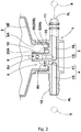
- Figure 2 is a sectional view of the cap unit 1 showing a state in which the bottle container 2 is mounted.
- the bottle container 2 has a well-known structure in which a small-diameter cylindrical mouth portion 2A for taking out the puncture repair liquid is protruded from the lower end of the container portion 2B accommodating the puncture repair liquid.
- the cap unit 1 will be described in its reference attitude such that the mouth portion 2A of the bottle container 2 is directed downward.
- the cap unit 1 in this embodiment has a cap main body 5 having a first flow path 3 and a second flow path 4, and a check valve 6 disposed in the first flow path 3.
- the first flow path 3 is for taking the compressed air from the compressor 8 in the bottle container 2.
- the second flow path 4 is for taking out the puncture repair liquid and the compressed air sequentially from the bottle container 2 by the taking-in of the compressed air.
- the cap main body 5 in this example is provided at the upper end of a cylindrical body portion 5A with a bottle mounting recess 9 for mounting the mouth portion 2A.
- the inner circumferential surface of the bottle mounting recess 9 is provided with an internal threaded portion to which the mouth portion 2A is attached by being screwed.
- a boss portion 10 extending into the bottle container 2, and an annular rib 23 surrounding the boss portion 10 so that they protrude therefrom.
- the boss portion 10 and the annular rib 23 in this example are formed concentrically with the bottle mounting recess 9.
- first connecting portion 11 for the compressor
- second connecting portion 12 for the tire so that they protrude therefrom.
- the first connecting portion 11 in this example is formed as a connection nozzle which can be coupled directly with a compressed air discharge port 8A (shown in Figure 1 ) of the compressor 8 without using a hose.
- the second connecting portion 12 in this example is formed as a hose connecting portion to which a hose extending from the tire T can be connected.
- the first flow path 3 has a vertical passage part 15 and a horizontal passage part 16.
- the vertical passage part 15 extends downwardly from the upper opening 3U which opens at the upper end of the boss portion 10.
- the horizontal passage part 16 extends substantially horizontally from a lower opening 3L which opens at the tip end of the first connecting portion 11, and intersects the vertical passage part 15 in the form of an L-shape.
- the second flow path 4 has a vertical passage part 17 and a horizontal passage part 18.
- the vertical passage part 17 extends downwardly from the upper opening 4U which opens in the bottom surface of the bottle mounting recess 9 and between the boss portion 10 and the annular rib 23.
- the horizontal passage part 18 extends substantially horizontally from a lower opening 4L which opens at the tip end of the second connecting portion 12, and intersects the vertical passage part 17 in the form of an L-shape.
- the check valve 6 In the first flow path 3, there is disposed the check valve 6 to prevent the backflow of the puncture repair liquid from the bottle container 2.
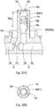
- valve seat portion 20 In the vertical passage part 15 of the first flow path 3, as shown in Figure 3(A) , there are disposed a valve seat portion 20, and a valve housing zone Y located on the upper side of the valve seat portion.
- the valve seat portion 20 has a cone-shaped valve seat surface 20s whose diameter is reduced toward the lower side.
- the check valve 6 is formed by a ball valve 21 disposed in the valve housing zone Y.
- the ball valve 21 is placed in the valve housing zone Y loosely to be movable up and down, and can close the valve seat portion 20 by the down motion due to its own weight. Thereby, the reverse flow of the puncture repair liquid toward the compressor is prevented.
- the upper opening 3U is provided with a locking portion 24 for preventing the ball valve 21 from falling out.
- the valve housing zone Y is formed as a zone between the valve seat portion 20 and the locking portion 24.
- the locking portion 24 is, as shown in Figure 3(B) , formed by a plurality of (eg, three) projections projecting from the inner circumferential surface of the boss portion 10. In this example, it is formed by melting the boss portion 10 partially by the use of, for example, a soldering iron or the like after the ball valve 21 has been inserted in the valve housing zone Y.
- the ball valve 21 is formed from a rubber elastic body having a specific gravity of 1.1 or more and a rebound resilience of 15% or less.
- the specific gravity of the puncture repair liquid is usually about 1.03, and the ball valve 21 is heavier than the puncture repair liquid. Therefore, when the puncture repair liquid is going to flow back, the ball valve 21 moves down immediately, and it is possible to close the valve seat 20. If the specific gravity is less than 1.1, the downward movement due to its own weight becomes slower, and the backflow of the puncture repair liquid can not be sufficiently prevented. Therefore, it is preferable that the specific gravity is 1.3 or more. The upper limit of the specific gravity is not particularly restricted.
- the ball valve 21 is formed from the rubber elastic body of low repulsion. Therefore, during storage, even if the ball valve 21 repeats collisions with the wall of the first flow path 3 due to vibrations during traveling of the vehicle, abnormal noise is hard to occur and quietness can be ensured. If the rebound resilience is more than 15%, the occurrence of abnormal noise can not be sufficiently prevented. Although the lower limit of the rebound resilience is not particularly restricted, it is difficult at present to produce a rubber whose rebound resilience is less than 2%. On the other hand, since the ball valve 21 is formed from the rubber elastic body, even if the valve seat portion 20 is formed from a plastic as a part of the cap main body 5, the sealing can be assured.
- butadiene rubber BR
- SBR styrene-butadiene
- IIR ethylene-propylene rubber
- EPM EP
- EPDM ethylene-propylene-diene rubber
- CSM chloroprene rubber
- Si acrylic rubber
- Q Q
- VMQ methyl methacrylate
- SR chlorosulfonated polyethylene rubber
- FKM fluoro rubber
- CO epichlorohydrin rubber
- the puncture repair kits K are stored or used in a temperature range from -30 degrees C to +60 degrees C. Therefore, it is preferable for the cap unit 1 that the ball valve 21 does not cause brittle fracture at least down to -30 degrees C. Accordingly, as the ball valve 21, the rubber elastic body having the low-temperature-embrittlement temperature of under - 30 degrees C is preferably used.
- the ratio Db/Da of the outer diameter Db of the ball valve 21 and the inner diameter Da of the valve housing zone Y is in a range of from 0.75 to 0.9. If the ratio Db/Da is less than 0.75, then the movement of the ball valve 21 in the valve housing zone Y becomes large, and the collision with the wall becomes strong. Thus, this is disadvantageous for suppressing the generation of abnormal noise. If the ratio Db/Da is more than 0.9, the flow rate of the high pressure air passing by the ball valve 2 is reduced, and the time required for injecting the puncture repair liquid and increasing the pressure becomes longer, which is disadvantageous to the puncture repair work.
- the ratio Db/L between the outer diameter Db of the ball valve 21 and the length L of the valve receiving area Y is 0.5 or more. If the ratio Db/L is less than 0.5, the movement of the ball valve 21 within the valve housing zone Y becomes large, which is disadvantageous for suppressing the generation of abnormal noise.
- the reference numeral 30 denotes a guide and stopper effective at the time of attaching the cap unit 1 to the compressor 8.
- the reference numeral 25 denotes an inner lid for preventing the puncture repair liquid from flowing out of the upper openings 3U and 4U before actuating the puncture repair kit K.
- This inner lid 25 has a first sealing portion 25A and a second sealing portion 25B.
- the first seal portion 25A hermetically contacts with the outer circumferential surface of the boss portion 10 to thereby seal the upper opening 3U.
- the second sealing portion 25B hermetically contacts with the outer circumferential surface of the annular rib 23 to thereby seal the upper opening 4U.
- cap units having the structure shown in Figure 2 were experimentally manufactured according to the specifications shown in Table 1, and each of the cap units was tested for the injecting and inflating time, and about whether the puncture repair liquid was flowed backward or not, and whether abnormal noise was generated from the ball valve or not.
- the specific gravity, rebound resilience, and low-temperature-embrittlement temperature of the ball valve were changed by changing the material of the rubber elastic body.
Landscapes
- Engineering & Computer Science (AREA)
- Mechanical Engineering (AREA)
- General Engineering & Computer Science (AREA)
- Check Valves (AREA)
Abstract
Description
- The present invention relates to a cap unit for puncture repair used for injecting a puncture repair liquid and compressed air sequentially into a punctured tire to temporary fix the puncture.
- For example, in the following Patent Document 1, a cap unit for puncture repair has been proposed.
In this cap unit, as shown inFigure 4 , a first flow path (a) for taking compressed air from a compressor into a bottle container, is provided with a check valve (b) to prevent a puncture repair liquid from flowing backward.
The check valve (b) in this proposal comprises a metal ball valve b1 disposed in a valve housing zone (c) in the first flow path (a), a rubber valve seat b2 disposed at the lower end of the valve housing zone (c), and a biasing spring b3 for pressing the ball valve b1 against the valve seat b2. Such structure leads to an increase in the cost. - On the other hand, in the following
Patent Document 2, a check valve having a simple structure is disclosed, wherein a metal ball valve is inserted in a first flow path provided with a valve seat portion.
In this check valve, the valve seat portion is closed by the weight of the ball valve.
In order to retain the ball valve, a locking pin is inserted in the upper end of the first flow path.
This structure is simple, and the parts are less in number, therefore, the cost can be reduced.
However, since the ball valve is free to move in the first flow path during storage by the vibrations of the vehicle during traveling, there is a problem such that abnormal noise is caused, making the passenger uncomfortable. -
- [Patent Document 1]
Japanese Patent Application Publication No.2011-189696 - [Patent Document 2]
Japanese Patent Application Publication No.2010-023244 - It is, therefore, an object of the present invention to provide a cap unit for puncture repair, in which abnormal noise occurring from a ball valve due to vibrations of the vehicle during traveling can be suppressed, while employing a simple structure to achieve a cost reduction.
- The present invention is characterized by comprising
a cap main body which is attached to a mouth portion of a bottle container containing a puncture repair liquid, and which has a first flow path for taking compressed air from a compressor into the bottle container, and a second flow path for taking out the puncture repair liquid and the compressed air sequentially from the bottle container by the taking-in of the compressed air, and
a check valve which is disposed in the first flow path to prevent a back-flow of the puncture repair liquid from the bottle container,
in a reference attitude of the bottle container whose mouth portion is directed downward, the first flow path has a vertical passage part extending downward from the top opening which opens within the bottle container, and
a valve seat portion formed in the vertical passage part,
the check valve is a ball valve disposed in a valve housing zone which is within the vertical passage part and on the upper side of the valve seat portion, and
the ball valve is made of a rubber elastic body having a specific gravity of 1.1 or more, and a rebound resilience of 15% or less. - In the cap unit for puncture repair according to the present invention, the rubber elastic body preferably has a low-temperature-embrittlement temperature of -30 degrees c or below.
- In the cap unit for puncture repair according to the present invention, the ratio Db/Da of the outer diameter Db of the ball valve and an inner diameter Da of the valve housing zone is preferably in the range from 0.75 to 0.9.
- In the cap unit for puncture repair according to the present invention, the ratio Db/L of the outer diameter Db of the ball valve and a length L of the valve housing zone is preferably 0.5 or more.
- The "specific gravity" is measured in accordance with JIS K6268 "Rubber, vulcanized-Determination of density".
- The "rebound resilience" is measured in accordance with JIS K6255 "Rubber, vulcanized or thermoplastic-Determination of rebound resilience" at a temperature of 23 degrees c.
- The "low-temperature-embrittlement temperature" is measured in accordance with JIS K6261 "Rubber, vulcanized or thermoplastic Determination of low temperature properties", "Low-temperature brittleness test".
- In the present invention, the check valve disposed in the first flow path is the ball valve disposed in the valve housing zone of the vertical passage part, and the ball valve is formed from the rubber elastic body having a specific gravity of 1.1 or more and a rebound resilience of 15% or less.
- Since the specific gravity of the ball valve is 1.1 or more, it can move down in the puncture repair liquid immediately by its own weight and can rapidly close the valve seat portion, which means that it can function as a check valve without using a biasing spring. Further, the ball valve is formed from the rubber elastic body of low repulsion. Therefore, even if the ball valve repeats collisions with the wall of the first flow path due to the vibrations during traveling of the vehicle, abnormal noise is hard to occur and quietness can be ensured.
-
- [
Figure 1 ] a perspective view showing an example of a puncture repair kit employing a cap unit according to the present invention. - [
Figure 2 ] a cross-sectional view of the cap unit. - [
Figure 3 ] (A) is a vertical cross-sectional view showing the check valve in closeup, (B) is a lateral cross-sectional view showing an engaging portion. - [
Figure 4 ] a cross-sectional view showing the structure of the check valve of the known cap unit. - Hereinafter, an embodiment of the present invention will be described in detail.
Figure 1 shows an example of a puncture repair kit K employing a cap unit 1 according to the present invention.
The puncture repair kit K has the cap unit 1, abottle container 2, and acompressor 8 so as to inject a puncture repair liquid and compressed air sequentially into a punctured tire to temporary fix the puncture. -
Figure 2 is a sectional view of the cap unit 1 showing a state in which thebottle container 2 is mounted.
Thebottle container 2 has a well-known structure in which a small-diametercylindrical mouth portion 2A for taking out the puncture repair liquid is protruded from the lower end of thecontainer portion 2B accommodating the puncture repair liquid. Hereinafter, the cap unit 1 will be described in its reference attitude such that themouth portion 2A of thebottle container 2 is directed downward. - As shown in
Figure 2 , the cap unit 1 in this embodiment has a capmain body 5 having afirst flow path 3 and asecond flow path 4, and acheck valve 6 disposed in thefirst flow path 3.
Thefirst flow path 3 is for taking the compressed air from thecompressor 8 in thebottle container 2.
Thesecond flow path 4 is for taking out the puncture repair liquid and the compressed air sequentially from thebottle container 2 by the taking-in of the compressed air. - More specifically, the cap
main body 5 in this example is provided at the upper end of acylindrical body portion 5A with a bottle mounting recess 9 for mounting themouth portion 2A.
The inner circumferential surface of thebottle mounting recess 9 is provided with an internal threaded portion to which themouth portion 2A is attached by being screwed.
In the bottom surface of the bottle mounting recess 9, there are disposed aboss portion 10 extending into thebottle container 2, and anannular rib 23 surrounding theboss portion 10 so that they protrude therefrom.
Theboss portion 10 and theannular rib 23 in this example are formed concentrically with thebottle mounting recess 9. - In the side surface of the cap
main body 5, there are disposed a first connectingportion 11 for the compressor, and a second connectingportion 12 for the tire so that they protrude therefrom.
The first connectingportion 11 in this example is formed as a connection nozzle which can be coupled directly with a compressedair discharge port 8A (shown inFigure 1 ) of thecompressor 8 without using a hose.
The second connectingportion 12 in this example is formed as a hose connecting portion to which a hose extending from the tire T can be connected. - Of the first and
second flow paths main body 5, thefirst flow path 3 has avertical passage part 15 and ahorizontal passage part 16.
Thevertical passage part 15 extends downwardly from theupper opening 3U which opens at the upper end of theboss portion 10. Thehorizontal passage part 16 extends substantially horizontally from alower opening 3L which opens at the tip end of the first connectingportion 11, and intersects thevertical passage part 15 in the form of an L-shape. - The
second flow path 4 has avertical passage part 17 and ahorizontal passage part 18.
Thevertical passage part 17 extends downwardly from theupper opening 4U which opens in the bottom surface of thebottle mounting recess 9 and between theboss portion 10 and theannular rib 23.
Thehorizontal passage part 18 extends substantially horizontally from alower opening 4L which opens at the tip end of the second connectingportion 12, and intersects thevertical passage part 17 in the form of an L-shape. - In the
first flow path 3, there is disposed thecheck valve 6 to prevent the backflow of the puncture repair liquid from thebottle container 2. - In the
vertical passage part 15 of thefirst flow path 3, as shown inFigure 3(A) , there are disposed avalve seat portion 20, and a valve housing zone Y located on the upper side of the valve seat portion.
Thevalve seat portion 20 has a cone-shapedvalve seat surface 20s whose diameter is reduced toward the lower side.
Thecheck valve 6 is formed by aball valve 21 disposed in the valve housing zone Y.
Theball valve 21 is placed in the valve housing zone Y loosely to be movable up and down, and can close thevalve seat portion 20 by the down motion due to its own weight.
Thereby, the reverse flow of the puncture repair liquid toward the compressor is prevented. - In this example, the
upper opening 3U is provided with a lockingportion 24 for preventing theball valve 21 from falling out. Accordingly, the valve housing zone Y is formed as a zone between thevalve seat portion 20 and the lockingportion 24. The lockingportion 24 is, as shown inFigure 3(B) , formed by a plurality of (eg, three) projections projecting from the inner circumferential surface of theboss portion 10.
In this example, it is formed by melting theboss portion 10 partially by the use of, for example, a soldering iron or the like after theball valve 21 has been inserted in the valve housing zone Y. - The
ball valve 21 is formed from a rubber elastic body having a specific gravity of 1.1 or more and a rebound resilience of 15% or less. - The specific gravity of the puncture repair liquid is usually about 1.03, and the
ball valve 21 is heavier than the puncture repair liquid. Therefore, when the puncture repair liquid is going to flow back, theball valve 21 moves down immediately, and it is possible to close thevalve seat 20.
If the specific gravity is less than 1.1, the downward movement due to its own weight becomes slower, and the backflow of the puncture repair liquid can not be sufficiently prevented. Therefore, it is preferable that the specific gravity is 1.3 or more. The upper limit of the specific gravity is not particularly restricted. - Moreover, the
ball valve 21 is formed from the rubber elastic body of low repulsion.
Therefore, during storage, even if theball valve 21 repeats collisions with the wall of thefirst flow path 3 due to vibrations during traveling of the vehicle, abnormal noise is hard to occur and quietness can be ensured.
If the rebound resilience is more than 15%, the occurrence of abnormal noise can not be sufficiently prevented.
Although the lower limit of the rebound resilience is not particularly restricted, it is difficult at present to produce a rubber whose rebound resilience is less than 2%.
On the other hand, since theball valve 21 is formed from the rubber elastic body, even if thevalve seat portion 20 is formed from a plastic as a part of the capmain body 5, the sealing can be assured. - As a material of the rubber elastic body of low repulsion, butadiene rubber (BR), styrene-butadiene (SBR), butyl rubber (IIR), ethylene-propylene rubber (EPM, EP), ethylene-propylene-diene rubber (EPDM), chloroprene rubber (CR), acrylic rubber (ACM, ANM), chlorosulfonated polyethylene rubber (CSM), silicone rubber (Si, Q, VMQ, SR), fluoro rubber (FKM, FRM), epichlorohydrin rubber (CO, ECO) and the like can be used.
- There is a tendency that the puncture repair kits K are stored or used in a temperature range from -30 degrees C to +60 degrees C. Therefore, it is preferable for the cap unit 1 that the
ball valve 21 does not cause brittle fracture at least down to -30 degrees C.
Accordingly, as theball valve 21, the rubber elastic body having the low-temperature-embrittlement temperature of under - 30 degrees C is preferably used. - In the
check valve 6, it is preferable that the ratio Db/Da of the outer diameter Db of theball valve 21 and the inner diameter Da of the valve housing zone Y is in a range of from 0.75 to 0.9.
If the ratio Db/Da is less than 0.75, then the movement of theball valve 21 in the valve housing zone Y becomes large, and the collision with the wall becomes strong. Thus, this is disadvantageous for suppressing the generation of abnormal noise. If the ratio Db/Da is more than 0.9, the flow rate of the high pressure air passing by theball valve 2 is reduced, and the time required for injecting the puncture repair liquid and increasing the pressure becomes longer, which is disadvantageous to the puncture repair work. - In the
check valve 6, it is also preferable that the ratio Db/L between the outer diameter Db of theball valve 21 and the length L of the valve receiving area Y is 0.5 or more.
If the ratio Db/L is less than 0.5, the movement of theball valve 21 within the valve housing zone Y becomes large, which is disadvantageous for suppressing the generation of abnormal noise. - In
Figure 1 , thereference numeral 30 denotes a guide and stopper effective at the time of attaching the cap unit 1 to thecompressor 8.
InFigure 2 , thereference numeral 25 denotes an inner lid for preventing the puncture repair liquid from flowing out of theupper openings
Thisinner lid 25 has afirst sealing portion 25A and asecond sealing portion 25B.
Thefirst seal portion 25A hermetically contacts with the outer circumferential surface of theboss portion 10 to thereby seal theupper opening 3U.
Thesecond sealing portion 25B hermetically contacts with the outer circumferential surface of theannular rib 23 to thereby seal theupper opening 4U.
During the puncture repair kit K is operating, the compressed air from thecompressor 8 pushes up theinner lid 25, and theinner lid 25 is automatically removed. - while detailed description has been made of a particularly preferred embodiment of the present invention, the present invention can be embodied in various forms without being limited to the illustrated embodiment.
- In order to confirm the effects of the present invention, cap units having the structure shown in
Figure 2 , were experimentally manufactured according to the specifications shown in Table 1, and each of the cap units was tested for the injecting and inflating time, and about whether the puncture repair liquid was flowed backward or not, and whether abnormal noise was generated from the ball valve or not.
The specific gravity, rebound resilience, and low-temperature-embrittlement temperature of the ball valve were changed by changing the material of the rubber elastic body. - (1) Injecting and inflating time: Using a common compressor, the time required to inject 400cc of a puncture repair liquid into the tire (195/65R15) and to inflate the tire from zero pressure to 250 kPa was measured. The ambient temperature was-30 degrees C.
- (2) whether the puncture repair liquid was flowed backward or not: After the injecting work of the puncture repair liquid was done, the cap unit was removed, and the presence or absence of the reverse flow into the first flow path was visually checked.
- (3) whether abnormal noise was generated or not: During traveling in the city streets, each cap unit put on the floor of the rear seat was checked by the driver whether abnormal noise due to the ball valve was generated or not. In the results,
- A denotes that abnormal noise was not generated,
- B denotes that abnormal noise was slightly generated, and
- C denotes that abnormal noise was generated.
- As shown in Table, it was confirmed that, in the working examples, abnormal noise generated from the ball valve due to vibrations of the vehicle during traveling can be suppressed.
-
- 1
- cap unit
- 2
- bottle container
- 2A
- mouth portion
- 3
- first flow path
- 3U
- opening
- 4
- second flow path
- 5
- cap main body
- 6
- check valve
- 8
- compressor
- 15
- vertical passage part
- 20
- valve seat portion
- 21
- ball valve
- Y
- valve housing zone
| Comparative Example 1 | Comparative Example 2 | Working Example 1 | Working Example 2 | Comparative Example 3 | Working Example 3 | Working Example 4 | Working Example 5 | Working Example 6 | Working Example 7 | |
| < Ball valve > | ||||||||||
| specific gravity | 7.8 | 1.0 | 1.1 | 1.1 | 1.1 | 1.1 | 1.1 | 1.1 | 1.1 | 1.1 |
| rebound resilience (%) | - | 4 | 4 | 4 | 20 | 4 | 15 | 10 | 13 | 6 |
| material | SUS | IIR | IIR | IIR | BR | IIR | BR | SBR | VMQ | FKM |
| low-temperature-embrittlement temperature (deg.C) | - | -40 | -40 | -40 | -40 | -40 | -60 | -30 | -80 | -30 |
| outer diameter Db (mm) | 3.5 | 3.5 | 2.8 | 3.5 | 3.5 | 3.8 | 3.5 | 3.5 | 3.5 | 3.5 |
| inner diameter Da of valve housing zone (mm) | 4.0 | 4.0 | 4.0 | 4.0 | 4.0 | 4.0 | 4.0 | 4.0 | 4.0 | 4.0 |
| length L of valve housing zone (mm) | 6.0 | 6.0 | 6.0 | 6.0 | 6.0 | 6.0 | 6.0 | 6.0 | 6.0 | 6.0 |
| ratio Db/Da | 0.88 | 0.88 | 0.70 | 0.88 | 0.88 | 0.95 | 0.88 | 0.88 | 0.88 | 0.88 |
| ratio Db/L | 0.58 | 0.58 | 0.47 | 0.58 | 0.58 | 0.63 | 0.58 | 0.58 | 0.58 | 0.58 |
| injecting and inflating time | 780 | 765 | 760 | 775 | 770 | 910 | 760 | 765 | 770 | 760 |
| presence or absence of backward flow | absence | presence | absence | absence | absence | absence | absence | absence | absence | absence |
| abnormal noise generation | C | A | B | A | C | A | A | A | A | A |
Claims (4)
- A cap unit for puncture repair which is characterized by comprising
a cap main body which is attached to a mouth portion of a bottle container containing a puncture repair liquid, and which has
a first flow path for taking compressed air from a compressor into the bottle container, and
a second flow path for taking out the puncture repair liquid and the compressed air sequentially from the bottle container by the taking-in of the compressed air, and
a check valve which is disposed in the first flow path to prevent a back-flow of the puncture repair liquid from the bottle container,
in a reference attitude of the bottle container whose mouth portion is directed downward, the first flow path has a vertical passage part extending downward from the top opening which opens within the bottle container, and
a valve seat portion formed in the vertical passage part,
the check valve is a ball valve disposed in a valve housing zone which is within the vertical passage part and on the upper side of the valve seat portion, and
the ball valve is made of a rubber elastic body having a specific gravity of 1.1 or more, and a rebound resilience of 15% or less. - The cap unit for puncture repair as set forth in claim 1, which is characterized in that the rubber elastic body has a low-temperature-embrittlement temperature of -30 degrees C or below.
- The cap unit for puncture repair as set forth in claim 1 or 2, which is characterized in that the ratio Db/Da of the outer diameter Db of the ball valve and an inner diameter Da of the valve housing zone is in a range from 0.75 to 0.9.
- The cap unit for puncture repair as set forth in claim 1, 2 or 3, which is characterized in that the ratio Db/L of the outer diameter Db of the ball valve and a length L of the valve housing zone is 0.5 or more.
Applications Claiming Priority (1)
| Application Number | Priority Date | Filing Date | Title |
|---|---|---|---|
| JP2016062323A JP2017170848A (en) | 2016-03-25 | 2016-03-25 | Cap unit for repairing puncture |
Publications (2)
| Publication Number | Publication Date |
|---|---|
| EP3222413A1 true EP3222413A1 (en) | 2017-09-27 |
| EP3222413B1 EP3222413B1 (en) | 2021-09-08 |
Family
ID=57406116
Family Applications (1)
| Application Number | Title | Priority Date | Filing Date |
|---|---|---|---|
| EP16200672.0A Active EP3222413B1 (en) | 2016-03-25 | 2016-11-25 | Cap unit for puncture repair |
Country Status (4)
| Country | Link |
|---|---|
| US (1) | US20170274605A1 (en) |
| EP (1) | EP3222413B1 (en) |
| JP (1) | JP2017170848A (en) |
| CN (1) | CN107225779A (en) |
Families Citing this family (4)
| Publication number | Priority date | Publication date | Assignee | Title |
|---|---|---|---|---|
| US11519428B2 (en) | 2017-10-17 | 2022-12-06 | Robert WENDLAND | Pneumatic pump control system |
| FR3118115A1 (en) * | 2020-12-21 | 2022-06-24 | Aurélien Cabarbaye | Liquid gas automatic sequence valve |
| JP7767832B2 (en) * | 2021-10-28 | 2025-11-12 | 住友ゴム工業株式会社 | Puncture repair fluid unit and puncture repair kit |
| DE102023205682A1 (en) * | 2023-06-16 | 2024-12-19 | Continental Reifen Deutschland Gmbh | Breakdown assistance kit with detachable connection element, system comprising such a breakdown assistance kit and a sealant bottle, method for replacing a connection element and fixing element for fixing a connection element |
Citations (6)
| Publication number | Priority date | Publication date | Assignee | Title |
|---|---|---|---|---|
| US20080230142A1 (en) * | 2007-03-19 | 2008-09-25 | Scott Noble Hickman | Tire sealant and air dispenser apparatus with a sealing mechanism |
| JP2010023244A (en) | 2008-07-15 | 2010-02-04 | Sumitomo Rubber Ind Ltd | Lid unit for sealant container |
| JP2011189696A (en) | 2010-03-16 | 2011-09-29 | Sumitomo Rubber Ind Ltd | Cap unit |
| US20110290372A1 (en) * | 2009-01-07 | 2011-12-01 | Try-Del Research Pty. Ltd. | Apparatus for repairing and inflating of damaged inflatable articles |
| US20120298255A1 (en) * | 2010-03-12 | 2012-11-29 | Sumitomo Rubber Industries, Ltd. | Cap unit |
| US20130068346A1 (en) * | 2011-09-21 | 2013-03-21 | Hui Long Ji | Tire Repair Device Containing Tire Cement |
Family Cites Families (6)
| Publication number | Priority date | Publication date | Assignee | Title |
|---|---|---|---|---|
| US5485882A (en) * | 1994-10-27 | 1996-01-23 | Exxon Production Research Company | Low-density ball sealer for use as a diverting agent in hostile environment wells |
| US5856376A (en) * | 1996-03-29 | 1999-01-05 | Nch Corporation | Tire puncture sealant |
| JP4133945B2 (en) * | 2004-06-28 | 2008-08-13 | 住友ゴム工業株式会社 | Tire puncture sealant supply and extraction device |
| US8671995B2 (en) * | 2010-07-02 | 2014-03-18 | Wen San Chou | Device for sealing and inflating inflatable object |
| TWI482908B (en) * | 2011-03-07 | 2015-05-01 | 周文三 | Air compressor for vehicle |
| DE102011018927A1 (en) * | 2011-04-28 | 2012-10-31 | Sumitomo Rubber Industries, Ltd. | Device for introducing air and / or sealing means into a tire |
-
2016
- 2016-03-25 JP JP2016062323A patent/JP2017170848A/en active Pending
- 2016-11-07 CN CN201610978355.7A patent/CN107225779A/en active Pending
- 2016-11-25 EP EP16200672.0A patent/EP3222413B1/en active Active
- 2016-12-16 US US15/382,029 patent/US20170274605A1/en not_active Abandoned
Patent Citations (6)
| Publication number | Priority date | Publication date | Assignee | Title |
|---|---|---|---|---|
| US20080230142A1 (en) * | 2007-03-19 | 2008-09-25 | Scott Noble Hickman | Tire sealant and air dispenser apparatus with a sealing mechanism |
| JP2010023244A (en) | 2008-07-15 | 2010-02-04 | Sumitomo Rubber Ind Ltd | Lid unit for sealant container |
| US20110290372A1 (en) * | 2009-01-07 | 2011-12-01 | Try-Del Research Pty. Ltd. | Apparatus for repairing and inflating of damaged inflatable articles |
| US20120298255A1 (en) * | 2010-03-12 | 2012-11-29 | Sumitomo Rubber Industries, Ltd. | Cap unit |
| JP2011189696A (en) | 2010-03-16 | 2011-09-29 | Sumitomo Rubber Ind Ltd | Cap unit |
| US20130068346A1 (en) * | 2011-09-21 | 2013-03-21 | Hui Long Ji | Tire Repair Device Containing Tire Cement |
Also Published As
| Publication number | Publication date |
|---|---|
| JP2017170848A (en) | 2017-09-28 |
| CN107225779A (en) | 2017-10-03 |
| US20170274605A1 (en) | 2017-09-28 |
| EP3222413B1 (en) | 2021-09-08 |
Similar Documents
| Publication | Publication Date | Title |
|---|---|---|
| EP3222413B1 (en) | Cap unit for puncture repair | |
| US20170282709A1 (en) | Vehicle | |
| JP4914394B2 (en) | Tire puncture repair equipment | |
| KR20120088775A (en) | Puncture repair kit | |
| CN101316696A (en) | Sealing inflating device | |
| KR20050103189A (en) | Fuel tank comprising a support for functional components and support for functional components of a motor vehicle fuel tank | |
| KR102133129B1 (en) | Valve device for fuel tank | |
| EP2497627B1 (en) | Puncture repair kit | |
| US20160250919A1 (en) | Fill limit vent valve for urea tank of vehicle | |
| EP3093132A1 (en) | Puncture repair kit | |
| JP5021242B2 (en) | Sealing pump up device | |
| JP2023536050A (en) | sealant jar | |
| US11007733B2 (en) | Puncture repair liquid holding container | |
| JP2017071129A (en) | Puncture repair liquid container | |
| JP5357703B2 (en) | Punk repair kit | |
| JP2010234795A (en) | Sealing pump-up device | |
| CN112483578A (en) | Damper for pantograph | |
| JP2012006346A (en) | Cap unit | |
| JP4006485B2 (en) | Tire air valve | |
| JP2018069496A (en) | Cap unit for puncture repair | |
| JP2011098463A (en) | Puncture repair kit | |
| CN111980783B (en) | Device for preventing urea water of vehicle from overflowing | |
| JP2012059803A (en) | Pressure release valve | |
| JP2011098458A (en) | Puncture repair kit | |
| US10023131B2 (en) | Covering members |
Legal Events
| Date | Code | Title | Description |
|---|---|---|---|
| PUAI | Public reference made under article 153(3) epc to a published international application that has entered the european phase |
Free format text: ORIGINAL CODE: 0009012 |
|
| STAA | Information on the status of an ep patent application or granted ep patent |
Free format text: STATUS: THE APPLICATION HAS BEEN PUBLISHED |
|
| AK | Designated contracting states |
Kind code of ref document: A1 Designated state(s): AL AT BE BG CH CY CZ DE DK EE ES FI FR GB GR HR HU IE IS IT LI LT LU LV MC MK MT NL NO PL PT RO RS SE SI SK SM TR |
|
| AX | Request for extension of the european patent |
Extension state: BA ME |
|
| STAA | Information on the status of an ep patent application or granted ep patent |
Free format text: STATUS: REQUEST FOR EXAMINATION WAS MADE |
|
| 17P | Request for examination filed |
Effective date: 20180216 |
|
| RBV | Designated contracting states (corrected) |
Designated state(s): AL AT BE BG CH CY CZ DE DK EE ES FI FR GB GR HR HU IE IS IT LI LT LU LV MC MK MT NL NO PL PT RO RS SE SI SK SM TR |
|
| GRAP | Despatch of communication of intention to grant a patent |
Free format text: ORIGINAL CODE: EPIDOSNIGR1 |
|
| STAA | Information on the status of an ep patent application or granted ep patent |
Free format text: STATUS: GRANT OF PATENT IS INTENDED |
|
| RIC1 | Information provided on ipc code assigned before grant |
Ipc: B29L 30/00 20060101ALN20210316BHEP Ipc: B29C 73/16 20060101AFI20210316BHEP |
|
| INTG | Intention to grant announced |
Effective date: 20210406 |
|
| GRAS | Grant fee paid |
Free format text: ORIGINAL CODE: EPIDOSNIGR3 |
|
| GRAA | (expected) grant |
Free format text: ORIGINAL CODE: 0009210 |
|
| STAA | Information on the status of an ep patent application or granted ep patent |
Free format text: STATUS: THE PATENT HAS BEEN GRANTED |
|
| AK | Designated contracting states |
Kind code of ref document: B1 Designated state(s): AL AT BE BG CH CY CZ DE DK EE ES FI FR GB GR HR HU IE IS IT LI LT LU LV MC MK MT NL NO PL PT RO RS SE SI SK SM TR |
|
| REG | Reference to a national code |
Ref country code: GB Ref legal event code: FG4D |
|
| REG | Reference to a national code |
Ref country code: AT Ref legal event code: REF Ref document number: 1428216 Country of ref document: AT Kind code of ref document: T Effective date: 20210915 Ref country code: CH Ref legal event code: EP |
|
| REG | Reference to a national code |
Ref country code: IE Ref legal event code: FG4D |
|
| REG | Reference to a national code |
Ref country code: DE Ref legal event code: R096 Ref document number: 602016063383 Country of ref document: DE |
|
| REG | Reference to a national code |
Ref country code: LT Ref legal event code: MG9D |
|
| REG | Reference to a national code |
Ref country code: NL Ref legal event code: MP Effective date: 20210908 |
|
| PG25 | Lapsed in a contracting state [announced via postgrant information from national office to epo] |
Ref country code: SE Free format text: LAPSE BECAUSE OF FAILURE TO SUBMIT A TRANSLATION OF THE DESCRIPTION OR TO PAY THE FEE WITHIN THE PRESCRIBED TIME-LIMIT Effective date: 20210908 Ref country code: RS Free format text: LAPSE BECAUSE OF FAILURE TO SUBMIT A TRANSLATION OF THE DESCRIPTION OR TO PAY THE FEE WITHIN THE PRESCRIBED TIME-LIMIT Effective date: 20210908 Ref country code: HR Free format text: LAPSE BECAUSE OF FAILURE TO SUBMIT A TRANSLATION OF THE DESCRIPTION OR TO PAY THE FEE WITHIN THE PRESCRIBED TIME-LIMIT Effective date: 20210908 Ref country code: LT Free format text: LAPSE BECAUSE OF FAILURE TO SUBMIT A TRANSLATION OF THE DESCRIPTION OR TO PAY THE FEE WITHIN THE PRESCRIBED TIME-LIMIT Effective date: 20210908 Ref country code: BG Free format text: LAPSE BECAUSE OF FAILURE TO SUBMIT A TRANSLATION OF THE DESCRIPTION OR TO PAY THE FEE WITHIN THE PRESCRIBED TIME-LIMIT Effective date: 20211208 Ref country code: NO Free format text: LAPSE BECAUSE OF FAILURE TO SUBMIT A TRANSLATION OF THE DESCRIPTION OR TO PAY THE FEE WITHIN THE PRESCRIBED TIME-LIMIT Effective date: 20211208 Ref country code: ES Free format text: LAPSE BECAUSE OF FAILURE TO SUBMIT A TRANSLATION OF THE DESCRIPTION OR TO PAY THE FEE WITHIN THE PRESCRIBED TIME-LIMIT Effective date: 20210908 Ref country code: FI Free format text: LAPSE BECAUSE OF FAILURE TO SUBMIT A TRANSLATION OF THE DESCRIPTION OR TO PAY THE FEE WITHIN THE PRESCRIBED TIME-LIMIT Effective date: 20210908 |
|
| REG | Reference to a national code |
Ref country code: AT Ref legal event code: MK05 Ref document number: 1428216 Country of ref document: AT Kind code of ref document: T Effective date: 20210908 |
|
| PG25 | Lapsed in a contracting state [announced via postgrant information from national office to epo] |
Ref country code: LV Free format text: LAPSE BECAUSE OF FAILURE TO SUBMIT A TRANSLATION OF THE DESCRIPTION OR TO PAY THE FEE WITHIN THE PRESCRIBED TIME-LIMIT Effective date: 20210908 Ref country code: GR Free format text: LAPSE BECAUSE OF FAILURE TO SUBMIT A TRANSLATION OF THE DESCRIPTION OR TO PAY THE FEE WITHIN THE PRESCRIBED TIME-LIMIT Effective date: 20211209 |
|
| PG25 | Lapsed in a contracting state [announced via postgrant information from national office to epo] |
Ref country code: AT Free format text: LAPSE BECAUSE OF FAILURE TO SUBMIT A TRANSLATION OF THE DESCRIPTION OR TO PAY THE FEE WITHIN THE PRESCRIBED TIME-LIMIT Effective date: 20210908 |
|
| PG25 | Lapsed in a contracting state [announced via postgrant information from national office to epo] |
Ref country code: IS Free format text: LAPSE BECAUSE OF FAILURE TO SUBMIT A TRANSLATION OF THE DESCRIPTION OR TO PAY THE FEE WITHIN THE PRESCRIBED TIME-LIMIT Effective date: 20220108 Ref country code: SM Free format text: LAPSE BECAUSE OF FAILURE TO SUBMIT A TRANSLATION OF THE DESCRIPTION OR TO PAY THE FEE WITHIN THE PRESCRIBED TIME-LIMIT Effective date: 20210908 Ref country code: SK Free format text: LAPSE BECAUSE OF FAILURE TO SUBMIT A TRANSLATION OF THE DESCRIPTION OR TO PAY THE FEE WITHIN THE PRESCRIBED TIME-LIMIT Effective date: 20210908 Ref country code: RO Free format text: LAPSE BECAUSE OF FAILURE TO SUBMIT A TRANSLATION OF THE DESCRIPTION OR TO PAY THE FEE WITHIN THE PRESCRIBED TIME-LIMIT Effective date: 20210908 Ref country code: PT Free format text: LAPSE BECAUSE OF FAILURE TO SUBMIT A TRANSLATION OF THE DESCRIPTION OR TO PAY THE FEE WITHIN THE PRESCRIBED TIME-LIMIT Effective date: 20220110 Ref country code: PL Free format text: LAPSE BECAUSE OF FAILURE TO SUBMIT A TRANSLATION OF THE DESCRIPTION OR TO PAY THE FEE WITHIN THE PRESCRIBED TIME-LIMIT Effective date: 20210908 Ref country code: NL Free format text: LAPSE BECAUSE OF FAILURE TO SUBMIT A TRANSLATION OF THE DESCRIPTION OR TO PAY THE FEE WITHIN THE PRESCRIBED TIME-LIMIT Effective date: 20210908 Ref country code: EE Free format text: LAPSE BECAUSE OF FAILURE TO SUBMIT A TRANSLATION OF THE DESCRIPTION OR TO PAY THE FEE WITHIN THE PRESCRIBED TIME-LIMIT Effective date: 20210908 Ref country code: CZ Free format text: LAPSE BECAUSE OF FAILURE TO SUBMIT A TRANSLATION OF THE DESCRIPTION OR TO PAY THE FEE WITHIN THE PRESCRIBED TIME-LIMIT Effective date: 20210908 Ref country code: AL Free format text: LAPSE BECAUSE OF FAILURE TO SUBMIT A TRANSLATION OF THE DESCRIPTION OR TO PAY THE FEE WITHIN THE PRESCRIBED TIME-LIMIT Effective date: 20210908 |
|
| REG | Reference to a national code |
Ref country code: DE Ref legal event code: R097 Ref document number: 602016063383 Country of ref document: DE |
|
| PG25 | Lapsed in a contracting state [announced via postgrant information from national office to epo] |
Ref country code: MC Free format text: LAPSE BECAUSE OF FAILURE TO SUBMIT A TRANSLATION OF THE DESCRIPTION OR TO PAY THE FEE WITHIN THE PRESCRIBED TIME-LIMIT Effective date: 20210908 |
|
| REG | Reference to a national code |
Ref country code: CH Ref legal event code: PL |
|
| PLBE | No opposition filed within time limit |
Free format text: ORIGINAL CODE: 0009261 |
|
| STAA | Information on the status of an ep patent application or granted ep patent |
Free format text: STATUS: NO OPPOSITION FILED WITHIN TIME LIMIT |
|
| PG25 | Lapsed in a contracting state [announced via postgrant information from national office to epo] |
Ref country code: LU Free format text: LAPSE BECAUSE OF NON-PAYMENT OF DUE FEES Effective date: 20211125 Ref country code: DK Free format text: LAPSE BECAUSE OF FAILURE TO SUBMIT A TRANSLATION OF THE DESCRIPTION OR TO PAY THE FEE WITHIN THE PRESCRIBED TIME-LIMIT Effective date: 20210908 Ref country code: BE Free format text: LAPSE BECAUSE OF NON-PAYMENT OF DUE FEES Effective date: 20211130 |
|
| REG | Reference to a national code |
Ref country code: BE Ref legal event code: MM Effective date: 20211130 |
|
| 26N | No opposition filed |
Effective date: 20220609 |
|
| GBPC | Gb: european patent ceased through non-payment of renewal fee |
Effective date: 20211208 |
|
| PG25 | Lapsed in a contracting state [announced via postgrant information from national office to epo] |
Ref country code: SI Free format text: LAPSE BECAUSE OF FAILURE TO SUBMIT A TRANSLATION OF THE DESCRIPTION OR TO PAY THE FEE WITHIN THE PRESCRIBED TIME-LIMIT Effective date: 20210908 Ref country code: LI Free format text: LAPSE BECAUSE OF NON-PAYMENT OF DUE FEES Effective date: 20211130 Ref country code: CH Free format text: LAPSE BECAUSE OF NON-PAYMENT OF DUE FEES Effective date: 20211130 |
|
| PG25 | Lapsed in a contracting state [announced via postgrant information from national office to epo] |
Ref country code: IE Free format text: LAPSE BECAUSE OF NON-PAYMENT OF DUE FEES Effective date: 20211125 Ref country code: GB Free format text: LAPSE BECAUSE OF NON-PAYMENT OF DUE FEES Effective date: 20211208 |
|
| PG25 | Lapsed in a contracting state [announced via postgrant information from national office to epo] |
Ref country code: IT Free format text: LAPSE BECAUSE OF FAILURE TO SUBMIT A TRANSLATION OF THE DESCRIPTION OR TO PAY THE FEE WITHIN THE PRESCRIBED TIME-LIMIT Effective date: 20210908 |
|
| PG25 | Lapsed in a contracting state [announced via postgrant information from national office to epo] |
Ref country code: HU Free format text: LAPSE BECAUSE OF FAILURE TO SUBMIT A TRANSLATION OF THE DESCRIPTION OR TO PAY THE FEE WITHIN THE PRESCRIBED TIME-LIMIT; INVALID AB INITIO Effective date: 20161125 |
|
| P01 | Opt-out of the competence of the unified patent court (upc) registered |
Effective date: 20230510 |
|
| PG25 | Lapsed in a contracting state [announced via postgrant information from national office to epo] |
Ref country code: CY Free format text: LAPSE BECAUSE OF FAILURE TO SUBMIT A TRANSLATION OF THE DESCRIPTION OR TO PAY THE FEE WITHIN THE PRESCRIBED TIME-LIMIT Effective date: 20210908 |
|
| PG25 | Lapsed in a contracting state [announced via postgrant information from national office to epo] |
Ref country code: MK Free format text: LAPSE BECAUSE OF FAILURE TO SUBMIT A TRANSLATION OF THE DESCRIPTION OR TO PAY THE FEE WITHIN THE PRESCRIBED TIME-LIMIT Effective date: 20210908 |
|
| PG25 | Lapsed in a contracting state [announced via postgrant information from national office to epo] |
Ref country code: TR Free format text: LAPSE BECAUSE OF FAILURE TO SUBMIT A TRANSLATION OF THE DESCRIPTION OR TO PAY THE FEE WITHIN THE PRESCRIBED TIME-LIMIT Effective date: 20210908 |
|
| PG25 | Lapsed in a contracting state [announced via postgrant information from national office to epo] |
Ref country code: MT Free format text: LAPSE BECAUSE OF FAILURE TO SUBMIT A TRANSLATION OF THE DESCRIPTION OR TO PAY THE FEE WITHIN THE PRESCRIBED TIME-LIMIT Effective date: 20210908 |
|
| PGFP | Annual fee paid to national office [announced via postgrant information from national office to epo] |
Ref country code: FR Payment date: 20250930 Year of fee payment: 10 |
|
| PGFP | Annual fee paid to national office [announced via postgrant information from national office to epo] |
Ref country code: DE Payment date: 20250930 Year of fee payment: 10 |