JP2012006346A - Cap unit - Google Patents
Cap unit Download PDFInfo
- Publication number
- JP2012006346A JP2012006346A JP2010146618A JP2010146618A JP2012006346A JP 2012006346 A JP2012006346 A JP 2012006346A JP 2010146618 A JP2010146618 A JP 2010146618A JP 2010146618 A JP2010146618 A JP 2010146618A JP 2012006346 A JP2012006346 A JP 2012006346A
- Authority
- JP
- Japan
- Prior art keywords
- compressed air
- inner lid
- flow path
- sealing agent
- cap
- Prior art date
- Legal status (The legal status is an assumption and is not a legal conclusion. Google has not performed a legal analysis and makes no representation as to the accuracy of the status listed.)
- Pending
Links
Images


Abstract
Description
本発明は、パンクしたタイヤにパンクシーリング剤と圧縮空気とを順次注入してパンクを応急的に修理するタイヤパンク応急修理装置に用いるキャップユニットに関する。 The present invention relates to a cap unit for use in a tire puncture emergency repairing device for repairing punctures by injecting a puncture sealing agent and compressed air sequentially into a punctured tire.
例えば下記の特許文献1に、パンクしたタイヤにパンクシーリング剤と圧縮空気とを順次注入してパンクを応急的に修理するタイヤパンク応急修理装置に用いるキャップユニットが提案されている。 For example, Patent Document 1 below proposes a cap unit for use in a tire puncture emergency repair device that punctures are repaired by sequentially injecting a puncture sealing agent and compressed air into a punctured tire.
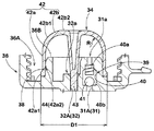
このキャップユニットaは、図10に示すように、パンクシーリング剤のボトル容器bを取り付けるキャップ本体c、及びこのキャップ本体cに形成される空気流路dとシーリング剤・圧縮空気取出し流路eとを閉じる内蓋fから構成される。具体的には、前記キャップ本体cは、ボトル容器bの口部b1を螺着する口部取付け凹部c1の底面に、ボス部c2を立設している。又前記内蓋fは、該ボス部c2の外周面に嵌着される筒状の胴部f1上端を上板部f2で閉じた内蓋本体faを有し、かつ該上板部f2には、前記シーリング剤・圧縮空気取出し流路eの一端をなすシーリング剤・圧縮空気取出し口e1を閉じる栓体部分fbを突出させている。 As shown in FIG. 10, the cap unit a includes a cap main body c to which a bottle container b of a puncture sealing agent is attached, an air flow path d formed in the cap main body c, a sealing agent / compressed air extraction flow path e It is comprised from the inner lid f which closes. Specifically, the cap body c has a boss portion c2 standing on the bottom surface of the mouth portion mounting recess c1 into which the mouth portion b1 of the bottle container b is screwed. The inner lid f has an inner lid body fa with an upper plate portion f2 closed at the upper end of a cylindrical body portion f1 fitted to the outer peripheral surface of the boss portion c2, and the upper plate portion f2 includes The plug part fb that closes the sealing agent / compressed air outlet e1 forming one end of the sealing agent / compressed air outlet passage e is protruded.
このキャップユニットaでは、前記ボトル容器bを取り付けた状態にて車載保管される。そしてパンク修理の際、この状態のユニットaに配管を施してコンプレッサgを作動させる。これにより、圧縮空気を前記空気流路dをへて内蓋本体fa内に流入させ、その内部圧力の上昇によって、前記内蓋fを前記ボス部c2から自動的に取り外させる。その後、ボトル容器b内のパンクシーリング剤及びコンプレッサgからの圧縮空気が、タイヤT内に順次注入され、パンクの応急修理とタイヤTのポンプアップとが連続的に行われる。 The cap unit a is stored on-board with the bottle container b attached. Then, at the time of puncture repair, piping is applied to the unit a in this state to operate the compressor g. As a result, compressed air flows into the inner lid body fa through the air flow path d, and the inner lid f is automatically removed from the boss portion c2 due to an increase in internal pressure. Thereafter, the puncture sealing agent in the bottle container b and the compressed air from the compressor g are sequentially injected into the tire T, and the puncture emergency repair and the tire T pump up are continuously performed.
このように前記内蓋fの機能として、保管時には前記ボス部c2に嵌着され、内部のパンクシーリング剤が空気流路dやシーリング剤・圧縮空気取出し流路eに流出するのを防止すること、及びパンク修理時にはコンプレッサgからの圧縮空気によってボス部c2から外れることが要求される。 As described above, as a function of the inner lid f, it is fitted to the boss part c2 during storage, and the internal puncture sealing agent is prevented from flowing into the air flow path d or the sealing agent / compressed air take-out flow path e. And at the time of puncture repair, it is required that the boss part c2 is detached by the compressed air from the compressor g.
しかしながら、前記内蓋fは、合成樹脂によって形成されるため、その弾性、即ちボス部c2との嵌合力は環境温度によって大きく変化する。従って、例えば、保管時にボス部c2から外れないように嵌合力を設定した場合、低温環境下で使用する時には、前記内蓋fの剛性が上昇してコンプレッサgからの圧縮空気では外れなくなり、パンク修理が行えなくなるという問題が生じる。なお図11に、環境温度と内蓋fの取り外し圧力との関係の一例が示されている。パンク修理用の圧縮空気は、通常乗用車用タイヤの許容最高空気圧(350kPa)程度であるため、この例では、約−33℃を下回ると、内蓋fが取り外せなくなるのが理解できる。 However, since the inner lid f is formed of synthetic resin, its elasticity, that is, the fitting force with the boss part c2, varies greatly depending on the environmental temperature. Therefore, for example, when the fitting force is set so that it does not come off from the boss part c2 during storage, the rigidity of the inner lid f increases when used in a low-temperature environment, and it cannot be removed by the compressed air from the compressor g. There arises a problem that repair cannot be performed. FIG. 11 shows an example of the relationship between the environmental temperature and the removal pressure of the inner lid f. Since the compressed air for puncture repair is normally about the maximum allowable air pressure (350 kPa) of passenger car tires, in this example, it can be understood that the inner lid f cannot be removed when it falls below about −33 ° C.
そこで本発明は、圧縮空気の圧力によって内蓋がボス部から外れないとき、手操作によって前記内蓋の栓体部分を上方に押し上げて内蓋をボス部から取り外す補助取外し手段を付加することを基本として、保管時における内蓋の外れ防止と、パンク修理時の内蓋の外れ不良防止とを両立させうるキャップユニットを提供することを目的としている。 Therefore, the present invention adds an auxiliary removing means for manually pushing up the plug portion of the inner lid and removing the inner lid from the boss when the inner lid does not come off from the boss due to the pressure of compressed air. The object of the present invention is to provide a cap unit that can achieve both prevention of inner lid removal during storage and prevention of inner lid removal failure during puncture repair.
上記課題を解決するために、本願請求項1の発明は、パンクシーリング剤を収容したボトル容器の口部に取り付くとともに、コンプレッサからの圧縮空気を前記ボトル容器内に送り込む空気流路、及びこの圧縮空気の送り込みにより前記ボトル容器からパンクシーリング剤と圧縮空気とを順次取り出すシーリング剤・圧縮空気取出し流路を有するキャップ本体、
並びに前記空気流路とシーリング剤・圧縮空気取出し流路とを閉じる内蓋を具えるキャップユニットであって、
前記キャップ本体は、上端部に、前記ボトル容器の口部を挿入して固定する口部取付け凹部と、この口部取付け凹部の底面から立上がりかつ外周面を前記内蓋が嵌着される内蓋嵌着面としたボス部とを具え、
しかも前記内蓋嵌着面よりも内側に、前記空気流路の一端をなす空気取入れ口と、前記シーリング剤・圧縮空気取出し流路の一端をなすシーリング剤・圧縮空気取出し口とを開口させるとともに、
前記内蓋は、前記内蓋嵌着面に嵌着される筒状の胴部上端を上板部で閉じた内蓋本体を有し、
かつ前記内蓋本体に、前記空気取入れ口から前記内蓋本体内に流入する圧縮空気の圧力によって前記内蓋を前記ボス部から取り外すために設けられ、前記上板部から下方に突出しかつ前記シーリング剤・圧縮空気取出し口内に挿入されて該シーリング剤・圧縮空気取出し口を塞ぐ栓体部分が配されるとともに、
前記キャップ本体に、前記圧縮空気の圧力によって前記内蓋がボス部から外れないとき、手操作によって前記内蓋の栓体部分を上方に押し上げて前記内蓋をボス部から取り外す補助取外し手段を設けたことを特徴としている。
In order to solve the above-mentioned problems, the invention of claim 1 of the present application attaches to the mouth of a bottle container containing a puncture sealing agent, and supplies an air flow path for sending compressed air from a compressor into the bottle container, and the compression A cap body having a sealing agent / compressed air take-out flow path for sequentially taking out the puncture sealing agent and compressed air from the bottle container by feeding air;
And a cap unit comprising an inner lid for closing the air flow path and the sealing agent / compressed air take-out flow path,
The cap main body has a mouth mounting recessed portion for inserting and fixing the mouth portion of the bottle container at an upper end portion, and an inner lid that rises from the bottom surface of the mouth mounting recess and has the inner lid fitted on the outer peripheral surface. It has a boss part as a fitting surface,
Moreover, an air intake opening that forms one end of the air flow path and a sealing agent / compressed air discharge opening that forms one end of the sealing agent / compressed air discharge flow path are opened inside the inner lid fitting surface. ,
The inner lid has an inner lid body in which an upper end of a cylindrical trunk portion fitted on the inner lid fitting surface is closed by an upper plate portion,
And the inner lid body is provided for removing the inner lid from the boss portion by the pressure of compressed air flowing into the inner lid body from the air intake port, and projects downward from the upper plate portion and the sealing And a plug body portion that is inserted into the agent / compressed air outlet and closes the sealing agent / compressed air outlet,
When the inner lid does not come off the boss portion due to the pressure of the compressed air, the cap body is provided with auxiliary removing means for manually pushing up the plug portion of the inner lid and removing the inner lid from the boss portion. It is characterized by that.
又請求項2の発明では、前記シーリング剤・圧縮空気取出し流路は、前記シーリング剤・圧縮空気取出し口から下方にのびる縦の流路部と、この縦の流路部の下端で折れ曲がりかつ前記シーリング剤・圧縮空気取出し流路の他端をなすシーリング剤・圧縮空気排出口まで横にのびる横の流路部とからなるL字状をなすとともに、
前記補助取外し手段は、前記縦の流路部の下端に連なり、前記キャップ本体の底面側で開口する下開放口まで前記縦の流路部とは一直線状に連なってのびる延長流路部と、この延長流路部内に上下に摺動可能に保持されかつ上方への摺動により、前記栓体部分を上方に押し上げうる押し軸とを有することを特徴としている。
In the invention of claim 2, the sealing agent / compressed air take-out flow path is bent at a vertical flow path portion extending downward from the sealing agent / compressed air take-out port, and a lower end of the vertical flow path portion, and The sealant and the compressed air take-out flow path form the other end of the sealant and the compressed air discharge port, and the side of the flow path extends to the L shape.
The auxiliary detachment means is connected to the lower end of the vertical flow path portion, and the extended flow path portion extends in a straight line from the vertical flow path portion to the lower opening that opens on the bottom surface side of the cap body. The extension channel portion is slidably held up and down and has a push shaft that can push up the plug portion by sliding upward.
又請求項3の発明では、前記押し軸は、前記延長流路部内にOリングを介して気密に配される挿入部分と、この挿入部分に連なり前記下開放口から下方に突出する突出部分とを具え、
しかも前記押し軸は、その上端が前記縦の流路部の下端よりも下方の下降位置と、前記栓体部分の下端を上方に押し上げて内蓋を取り外す上昇位置との間を移動しうるとともに、前記突出部分に、前記押し軸を下方に付勢して前記下降位置に復帰させるバネ手段を設けたことを特徴としている。
According to a third aspect of the present invention, the push shaft includes an insertion portion that is airtightly arranged in the extension flow path portion via an O-ring, and a protrusion portion that continues to the insertion portion and protrudes downward from the lower opening. With
Moreover, the push shaft can move between a descending position whose upper end is lower than the lower end of the vertical flow path portion and an elevated position where the lower end of the plug body portion is pushed upward to remove the inner lid. The protruding portion is provided with spring means for urging the push shaft downward to return it to the lowered position.
又請求項4の発明では、前記押し軸が、栓体部分を押し上げる距離は、1〜5mmであることを特徴としている。
The invention according to
本発明は叙上の如く、内蓋本体に、シーリング剤・圧縮空気取出し口を塞ぐ栓体部分を設けている。そのため、通常の使用環境においては、パンク修理時、コンプレッサからの圧縮空気によって内蓋を自動的に取り外しでき、使い勝手を高めうる。又キャップ本体に、補助取外し手段を設けているため、低温環境下などの特別な使用環境においても、確実に内蓋をボス部から取り外してパンク修理を行いうるなど、キャップユニットの信頼性を高めることができる。 In the present invention, as described above, the inner lid body is provided with a plug portion for closing the sealing agent / compressed air outlet. Therefore, in a normal use environment, the inner lid can be automatically removed by compressed air from the compressor at the time of puncture repair, and the usability can be improved. In addition, since the cap body is provided with auxiliary removal means, the cap unit can be reliably removed by removing the inner lid from the boss in a special use environment, such as in a low-temperature environment. be able to.
以下、本発明の実施の形態について、詳細に説明する。
図1は、本発明のキャップユニット2を用いたタイヤパンク応急修理装置1の使用状態を示す斜視図であって、前記タイヤパンク応急修理装置1は、パンクシーリング剤を収容したボトル容器3をキャップユニット2に取り付けたボトルユニット4と、このボトルユニット4に接続されるコンプレッサ5とを具える。
Hereinafter, embodiments of the present invention will be described in detail.
FIG. 1 is a perspective view showing a use state of a tire puncture emergency repair device 1 using a cap unit 2 of the present invention. The tire puncture emergency repair device 1 caps a
前記コンプレッサ5とボトルユニット4とは、パンク修理現場において、本例では、ホース類を介在させることなく直接接続される。又前記キャップユニット2に設けるシーリング剤・圧縮空気排出口32bには、一端がタイヤTの空気バルブTvに接続される送給ホース6の他端が連結されている。又ボトルユニット4は、前記キャップユニット2を下方に向けた倒立状態にて前記コンプレッサ5に接続される。なお図中の符号9は、コンプレッサ5駆動用の電源プラグであって、本例では、自動車のシガーソケットに接続される。又符号10は、コンプレッサ5の圧力計である。
In the present example, the
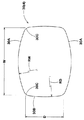
次に、前記ボトル容器3は、図3に示すように、胴部30の下端に、パンクシーリング剤を出し入れしうる小径円筒状の口部7を突出している。本例では、前記胴部30は、図9に示すように、その高さ方向と直角な横断面が、ボトル外側に向かって凸円弧状に湾曲する一対の長辺部30Aと、凸円弧状に湾曲する一対の短辺部30Bとで四辺を囲む略矩形状に形成される。そして、前記長辺部30Aの長さをW、長辺部30Aの曲率半径をRW、前記短辺部30Bの長さをD、短辺部30Bの曲率半径をRDとしたとき、本例では、下記式(1)〜(3)を充足するように設定されている。
1.3≦W/D≦1.7 −−−(1)
0.5≦RW/W≦3.0 −−−(2)
0.5≦RD/D≦20.0 −−−(3)
Next, as shown in FIG. 3, the
1.3 ≦ W / D ≦ 1.7 (1)
0.5 ≦ RW / W ≦ 3.0 (2)
0.5 ≦ RD / D ≦ 20.0 −−− (3)
ここで、車両内、例えばトランク内におけるタイヤパンク応急修理装置1の収納性を考慮したとき、前記コンプレッサ5が略直方体状をなすため、ボトル容器3の胴部30も、略直方体状に形成するのが好ましい。しかしパンク修理の際、ボトル容器3には、例えば350kPa近くの高内圧が作用する。このとき、前記胴部30が断面円形状の場合には、内圧によって前記胴部30が半径方向に均等に膨張するため、圧縮空気充填時の変形があまり認識されず、ユーザーへの不安感は低いものとなる。しかしながら、胴部30が断面矩形状の場合には、内圧による膨れは均一ではなく、断面矩形状から断面円形状に近づくように膨張するなど、その変形量は実際よりも大きく感じられる。そのために、耐圧範囲内とはいえ、ユーザーに破裂などの不安を与える可能性がある。
Here, when considering the stowability of the tire puncture emergency repair device 1 in the vehicle, for example, in the trunk, the
そこで本例では、予め、前記長辺部30A及び短辺部30Bをそれぞれ凸円弧状として、膨張時の変形形状に近い形状に形成している。そのため、収納性を向上しながら、圧縮空気充填時の変形があまり認識されなくなり、使用者の不安を低く抑えることが可能となる。
Therefore, in this example, the
本発明者の実験の結果、前記不安感を抑えるためには、長辺側の膨張量を抑えることが重要であり、そのためには、長辺側の長さWを大きく、かつ曲率半径RWを小さく設定するのが好ましい。もし前記比W/Dが1.3を下回る、或いは比RW/Wが3.0を越えると、前記長さWが相対的に小、或いは曲率半径RWが大きくなって長辺側の膨張量の増加を招く。逆に、前記比W/Dが1.7を越える、或いは比RW/Wが0.5を下回る場合には、収納性に不利が生じる。又前記比RD/Dが20.0を越えると、短辺側の膨張量が増大して、圧縮空気充填時の変形が大きくなり、逆に、比RD/Dが0.5を下回ると、収納性に不利を招く。このような観点から比W/Dの下限は1.4以上がより好ましく、又上限は1.6以下がより好ましい。又比RW/Wの下限は0.7以上がより好ましく、又上限は2.0以下がより好ましい。又比RD/Dの下限は1.0以上がより好ましく、又上限は10.0以下がより好ましい。 As a result of the inventor's experiment, in order to suppress the feeling of anxiety, it is important to suppress the amount of expansion on the long side, and for that purpose, the length W on the long side is increased and the radius of curvature RW is increased. It is preferable to set a small value. If the ratio W / D is less than 1.3 or the ratio RW / W is more than 3.0, the length W is relatively small or the radius of curvature RW is large and the expansion amount on the long side is increased. Increase. On the contrary, when the ratio W / D exceeds 1.7 or the ratio RW / W is less than 0.5, the storage property is disadvantageous. If the ratio RD / D exceeds 20.0, the amount of expansion on the short side increases, and the deformation at the time of filling with compressed air increases. Conversely, if the ratio RD / D is less than 0.5, This causes a disadvantage in storage. From such a viewpoint, the lower limit of the ratio W / D is more preferably 1.4 or more, and the upper limit is more preferably 1.6 or less. The lower limit of the ratio RW / W is more preferably 0.7 or more, and the upper limit is more preferably 2.0 or less. The lower limit of the ratio RD / D is more preferably 1.0 or more, and the upper limit is more preferably 10.0 or less.
なお長辺部30Aと短辺部30Bとが交わるコーナ部分は、応力集中を緩和して耐圧性能を高めるために、曲率半径15mm±5mmの円弧30Cにて形成するのが好ましい。
The corner portion where the
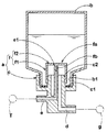
次に、前記キャップユニット2は、前記図2、3に示す如く、キャップ本体33と、それに取り付く内蓋34とを具え、前記キャップ本体33は、前記ボトル容器3の口部7に取り付く。又キャップ本体33は、前記コンプレッサ5からの圧縮空気を前記ボトル容器3内に送り込む空気流路31と、この圧縮空気の送り込みにより前記ボトル容器3からパンクシーリング剤と圧縮空気とを順次取り出すシーリング剤・圧縮空気取出し流路32とを有する。又前記内蓋34は、前記空気流路31とシーリング剤・圧縮空気取出し流路32とをボトル容器3内で閉じ、保管中にパンクシーリング剤が前記空気流路31およびシーリング剤・圧縮空気取出し流路32に流出するのを防止する。
Next, as shown in FIGS. 2 and 3, the cap unit 2 includes a
具体的には、前記キャップ本体33は、底面33Sをなす底板部分35と、前記ボトル容器3の口部7を取り付ける口部取付部分36と、その間に配されるくびれ部分37とを一体に具える。
Specifically, the
そして、前記口部取付部分36は、前記口部7を挿入して固定する口部取付け凹部36Aと、この口部取付け凹部36Aの底面から立ち上がるボス部36Bとを有する。前記口部取付け凹部36Aは、その内壁面に設ける内ネジにより前記口部7を螺着しうる。又前記ボス部36Bは、その外周面を前記内蓋34が嵌着される内蓋嵌着面38とした円柱状をなし、その上面には、前記空気流路31の一端をなす空気取入れ口31aと、前記シーリング剤・圧縮空気取出し流路32の一端をなすシーリング剤・圧縮空気取出し口32aとが開口する。
The mouth
前記空気流路31は、前記空気取入れ口31aから下方にのびる縦の流路部31Aと、この縦の流路部31Aの下端で折れ曲がりかつ前記空気流路31の他端をなす空気供給口31bまで横にのびる横の流路部31BとからなるL字状をなす。又本例では、前記縦の流路部31Aには、前記空気取入れ口31aからパンクシーリング剤が逆流するのを阻止するための一方弁39が形成される。
The
この一方弁39は、図4に示すように、前記縦の流路部31Aの中間に形成される大径な弁室40と、この弁室40内に昇降可能に収容される球弁41とを具える。前記弁室40には、その下端部に前記球弁41により封止される弁座部40bが設けられるとともに、弁室40の上端部には、圧縮空気を流過させうる圧縮空気流過部40aが設けられる。この圧縮空気流過部40aは、本例では、螺旋溝を有するコイル状体からなり、圧縮空気によって上昇する球弁41によって前記弁室40の上端部が封止されるのを防止する。
As shown in FIG. 4, the one-
又前記シーリング剤・圧縮空気取出し流路32は、前記シーリング剤・圧縮空気取出し口32aから下方にのびる縦の流路部32Aと、この縦の流路部32Aの下端で折れ曲がりかつ前記シーリング剤・圧縮空気取出し流路32の他端をなすシーリング剤・圧縮空気排出口32bまで横にのびる横の流路部32BとからなるL字状をなす。本例では、前記縦の流路部32Aは前記ボス部36Bの中心を通る中心孔として形成される。
The sealing agent / compressed air take-out
次に、前記内蓋34は、例えばポリエチレン、ポリプロピレンなどの弾性変形可能な合成樹脂材からなり、図4に拡大して示すように、内周面が前記内蓋嵌着面38に嵌着される円筒状の胴部42aの上端を、上板部42bで閉じる内蓋本体42と、前記上板部42bから下方に突出しかつ前記シーリング剤・圧縮空気取出し口32a内に挿入されて該シーリング剤・圧縮空気取出し口32aを塞ぐ栓体部分43とを具える。
Next, the
前記上板部42bは、本例では、前記胴部42aとは曲率半径Rの円弧で接続する円弧部分42b1を有する略半球面状をなし、前記曲率半径Rを、前記胴部42aの内径D1の0.3〜0.5倍の範囲に設定している。なお前記曲率半径Rは、前記円弧部分42b1の内面における曲率半径であって、R=0.5×D1 のとき、前記上板部42bは、実質的に前記円弧部分42b1のみからなる半球面状に形成される。又0.3×D1≦R<0.5×D1 のときには、前記上板部42bは、本例のように、前記円弧部分42b1と、上板部42bの頂部をなす平らな平滑部42b2とから形成される。
In this example, the
又前記胴部42aの外周面には、本例では、その下端部に、周方向に連続してのびる補強用の厚肉部分42a1が形成されるとともに、その内周面には、前記内蓋嵌着面38に設ける浅い周方向の係止溝44と係合する係合突起42a2が突出している。
Further, in the present embodiment, a reinforcing thick portion 42a1 extending continuously in the circumferential direction is formed on the outer peripheral surface of the
本例の内蓋34は、前述の如く、前記上板部42bが略半球面状をなし、かつ前記胴部42aの下端部に周方向に連続してのびる補強用の厚肉部分42a1を設けているため、内蓋本体42内に圧縮空気が充填された際には、内蓋34は、図5に示すように、円弧部分42b1から胴部42a上端側にかけて横に広がる変形をなし、逆に前記胴部42a下端側では厚肉部分42a1により補強、タガ締めされているため、横に広がりにくくなる。そのため、圧縮空気充填時、胴部42aと内蓋嵌着面38との間に隙間が生じにくくなる。従って、隙間が生じた場合に、そこから漏れる空気によってボトル容器3内の内圧が上昇し、内蓋34がボス部36Bから外れにくくなるのを抑えることができる。
As described above, the
次に、本実施形態のキャップユニット2には、前記圧縮空気の圧力によって前記内蓋34がボス部36Bから外れないとき、手操作によって前記内蓋34の栓体部分43を上方に押し上げて強制的に取り外す補助取外し手段45を設けている。
Next, in the cap unit 2 of this embodiment, when the
この補助取外し手段45は、前記図6(A)、(B)に示すように、前記縦の流路部32Aの下端に連なり、前記キャップ本体33の底面33S側で開口する下開放口46aまで前記縦の流路部32Aとは一直線状に連なってのびる延長流路部46と、この延長流路部46内に上下に摺動可能に保持されかつ上方への摺動により、前記栓体部分43を上方に押し上げうる押し軸47とを含んで構成される。
As shown in FIGS. 6 (A) and 6 (B), the auxiliary detaching means 45 is connected to the lower end of the vertical
具体的には、前記押し軸47は、前記延長流路部46内にOリングを介して気密に配される挿入部分49と、この挿入部分49に連なり前記下開放口46aから下方に突出する突出部分50とを具える。そして、この押し軸47は、その上端が前記縦の流路部32Aの下端Qよりも下方の下降位置YL(図6(A)に示す)と、前記栓体部分43の下端を上方に押し上げて内蓋34を取り外す上昇位置YU(図6(B)に示す)との間を上下に移動しうる。なお押し軸47の下端部には、手操作によって押し軸47を上方に押し上げるレバー51が配されるとともに、前記キャップ本体33の底板部分35には、前記下降位置YLで前記押し軸47の下端部と当接するストッパ52が形成される。又前記突出部分50には、前記押し軸47を下方に付勢して前記下降位置YLに復帰させるバネ手段53が配される。
Specifically, the
ここで、前記補助取外し手段45では、前記押し軸47によって栓体部分43を縦の流路部32Aから完全に押し出す必要はなく、前記内蓋34とボス部36Bとの嵌合が弛む程度、本例では前記係合突起42a2を前記係止溝44から外れさせることで充分である。従って、本例では、押し軸47による栓体部分43を押し上げる距離は、1〜5mm程度とし、嵌合が弛んだ後は、圧縮空気の圧力によって内蓋34をボス部36Bから取り外す。
Here, in the
次に、前記キャップ本体33の前記空気供給口31bは、前記コンプレッサ5に設ける嵌合凹部54に直接接続する接続ノズル55の先端で開口する。
Next, the
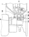
図7、8に示すように、コンプレッサ5に設ける前記嵌合凹部54は、コンプレッサ5における圧縮空気形成用のシリンダポンプ60からのびる圧縮空気供給流路61に導通している。この嵌合凹部54は、内径一定の平行孔部54Aの前後に、シリンダポンプ60に向かって先細コーン状をなす前後のテーパ面部54B、54Cを連設している。
As shown in FIGS. 7 and 8, the
又前記接続ノズル55は、平行なノズル本体55Aの先端側に、先細コーン状のテーパ面部55Bを具えるとともに、ノズル本体55Aの外周には、前記嵌合凹部54の内周面との間をシールするOリング65が装着される。本例では、消耗品であるOリング65を、キャップ本体33側に配することで、コンプレッサ5をメンテナンスすることなく繰り返し使用することが可能となる。
The connecting
なお前記嵌合凹部54の後のテーパ面部54Cは、前記テーパ面部55Bとほぼ同傾斜をなし、前記接続ノズル55を嵌合凹部54内に挿入する際、前記テーパ面部55Bを受けて同心に保持する受け面として機能する。
The tapered
又前記キャップ本体33には、前記接続ノズル55の両側(本例では上下)に、一対の係止爪62が突設されるとともに、前記コンプレッサ5には、前記係止爪62と向き合う位置に、該係止爪62と係合することにより前記直接接続の状態にて前記コンプレッサ5とボトルユニット4とを固定する爪係合穴63が形成される。
The
前記係止爪62は、前記キャップ本体33から接続ノズル55と平行にのびる主部62Aの先端に、直角三角形状のフック部62Bを外向きに突設している。そして、前記爪係合穴63は、前記係止爪62が入る本例では矩形穴状をなし、その上下縁で前記フック部62Bと係合し、抜け止めされる。なお係止爪62とキャップ本体33とは、例えばナイロン、ポリプロピレン、ポリエチレンなどのプラスチック、或いはこれらにグラスファイバなどの短繊維を配合した強化プラスチックからなる一体成形体として形成される。又前記爪係合穴63は、本例では、前記嵌合凹部54に支持されるフレーム枠64よって形成されるとともに、このフレーム枠64と、嵌合凹部54と、シリンダポンプ60とは、例えば亜鉛合金、アルミ合金などの軽量合金からなる一体成形体として形成される。
The locking
以上、本発明の特に好ましい実施形態について詳述したが、本発明は図示の実施形態に限定されることなく、種々の態様に変形して実施しうる。 As mentioned above, although especially preferable embodiment of this invention was explained in full detail, this invention is not limited to embodiment of illustration, It can deform | transform and implement in a various aspect.
1 キャップユニット
3 ボトル容器
7 口部
5 コンプレッサ
31 空気流路
31a 空気取入れ口
32 シーリング剤・圧縮空気取出し流路
32a シーリング剤・圧縮空気取出し口
32A 縦の流路部
32b シーリング剤・圧縮空気排出口
32B 横の流路部
33 キャップ本体
33S 底面
34 内蓋
36A 口部取付け凹部
36B ボス部
38 内蓋嵌着面
42 内蓋本体
42a 胴部
42b 上板部
43 栓体部分
45 補助取外し手段
46 延長流路部
46a 下開放口
47 押し軸
48 Oリング
49 挿入部分
50 突出部分
53 バネ手段
Q 下端
YL 下降位置
YU 上昇位置
DESCRIPTION OF SYMBOLS 1
Claims (4)
並びに前記空気流路とシーリング剤・圧縮空気取出し流路とを閉じる内蓋を具えるキャップユニットであって、
前記キャップ本体は、上端部に、前記ボトル容器の口部を挿入して固定する口部取付け凹部と、この口部取付け凹部の底面から立上がりかつ外周面を前記内蓋が嵌着される内蓋嵌着面としたボス部とを具え、
しかも前記内蓋嵌着面よりも内側に、前記空気流路の一端をなす空気取入れ口と、前記シーリング剤・圧縮空気取出し流路の一端をなすシーリング剤・圧縮空気取出し口とを開口させるとともに、
前記内蓋は、前記内蓋嵌着面に嵌着される筒状の胴部上端を上板部で閉じた内蓋本体を有し、
かつ前記内蓋本体に、前記空気取入れ口から前記内蓋本体内に流入する圧縮空気の圧力によって前記内蓋を前記ボス部から取り外すために設けられ、前記上板部から下方に突出しかつ前記シーリング剤・圧縮空気取出し口内に挿入されて該シーリング剤・圧縮空気取出し口を塞ぐ栓体部分が配されるとともに、
前記キャップ本体に、前記圧縮空気の圧力によって前記内蓋がボス部から外れないとき、手操作によって前記内蓋の栓体部分を上方に押し上げて前記内蓋をボス部から取り外す補助取外し手段を設けたことを特徴とするキャップユニット。 The puncture sealing agent and the compressed air are attached to the mouth of the bottle container containing the puncture sealing agent, the compressed air from the compressor is sent into the bottle container, and the puncture sealing agent and the compressed air are sent from the bottle container by feeding the compressed air. Cap body with sealing agent and compressed air take-out flow path to be taken out sequentially,
And a cap unit comprising an inner lid for closing the air flow path and the sealing agent / compressed air take-out flow path,
The cap main body has a mouth mounting recessed portion for inserting and fixing the mouth portion of the bottle container at an upper end portion, and an inner lid that rises from the bottom surface of the mouth mounting recess and has the inner lid fitted on the outer peripheral surface. It has a boss part as a fitting surface,
Moreover, an air intake opening that forms one end of the air flow path and a sealing agent / compressed air discharge opening that forms one end of the sealing agent / compressed air discharge flow path are opened inside the inner lid fitting surface. ,
The inner lid has an inner lid body in which an upper end of a cylindrical trunk portion fitted on the inner lid fitting surface is closed by an upper plate portion,
And the inner lid body is provided for removing the inner lid from the boss portion by the pressure of compressed air flowing into the inner lid body from the air intake port, and projects downward from the upper plate portion and the sealing And a plug body portion that is inserted into the agent / compressed air outlet and closes the sealing agent / compressed air outlet,
When the inner lid does not come off the boss portion due to the pressure of the compressed air, the cap body is provided with auxiliary removing means for manually pushing up the plug portion of the inner lid and removing the inner lid from the boss portion. Cap unit characterized by that.
前記補助取外し手段は、前記縦の流路部の下端に連なり、前記キャップ本体の底面側で開口する下開放口まで前記縦の流路部とは一直線状に連なってのびる延長流路部と、この延長流路部内に上下に摺動可能に保持されかつ上方への摺動により、前記栓体部分を上方に押し上げうる押し軸とを有することを特徴とする請求項1記載のキャップユニット。 The sealing agent / compressed air take-out flow path is bent at a vertical flow path portion extending downward from the sealing agent / compressed air take-out port, and a lower end of the vertical flow path portion, and the sealing agent / compressed air take-out flow path. In addition to forming an L-shape consisting of a horizontal flow path part extending horizontally to the sealing agent / compressed air discharge port forming the other end of
The auxiliary detachment means is connected to the lower end of the vertical flow path portion, and the extended flow path portion extends in a straight line from the vertical flow path portion to the lower opening that opens on the bottom surface side of the cap body. 2. The cap unit according to claim 1, further comprising a push shaft that is slidably held in the extended flow path portion and can push up the plug body portion by sliding upward.
しかも前記押し軸は、その上端が前記縦の流路部の下端よりも下方の下降位置と、前記栓体部分の下端を上方に押し上げて内蓋を取り外す上昇位置との間を移動しうるとともに、前記突出部分に、前記押し軸を下方に付勢して前記下降位置に復帰させるバネ手段を設けたことを特徴とする請求項2記載のキャップユニット。 The push shaft includes an insertion portion that is airtightly arranged in the extension channel portion via an O-ring, and a protruding portion that continues to the insertion portion and projects downward from the lower opening,
Moreover, the push shaft can move between a descending position whose upper end is lower than the lower end of the vertical flow path portion and an elevated position where the lower end of the plug body portion is pushed upward to remove the inner lid. 3. The cap unit according to claim 2, wherein a spring means for urging the push shaft downward to return to the lowered position is provided at the projecting portion.
The cap unit according to claim 3, wherein a distance by which the push shaft pushes up the plug body portion is 1 to 5 mm.
Priority Applications (1)
| Application Number | Priority Date | Filing Date | Title |
|---|---|---|---|
| JP2010146618A JP2012006346A (en) | 2010-06-28 | 2010-06-28 | Cap unit |
Applications Claiming Priority (1)
| Application Number | Priority Date | Filing Date | Title |
|---|---|---|---|
| JP2010146618A JP2012006346A (en) | 2010-06-28 | 2010-06-28 | Cap unit |
Publications (1)
| Publication Number | Publication Date |
|---|---|
| JP2012006346A true JP2012006346A (en) | 2012-01-12 |
Family
ID=45537456
Family Applications (1)
| Application Number | Title | Priority Date | Filing Date |
|---|---|---|---|
| JP2010146618A Pending JP2012006346A (en) | 2010-06-28 | 2010-06-28 | Cap unit |
Country Status (1)
| Country | Link |
|---|---|
| JP (1) | JP2012006346A (en) |
Cited By (3)
| Publication number | Priority date | Publication date | Assignee | Title |
|---|---|---|---|---|
| JP2014516824A (en) * | 2011-04-28 | 2014-07-17 | 住友ゴム工業株式会社 | Device for introducing air and / or sealant into a tire |
| JP2016107640A (en) * | 2014-12-04 | 2016-06-20 | 周 文三 | Seal pumping device structure |
| CN114302660A (en) * | 2019-11-04 | 2022-04-08 | Lg电子株式会社 | Food processor |
Citations (1)
| Publication number | Priority date | Publication date | Assignee | Title |
|---|---|---|---|---|
| JP2011185434A (en) * | 2010-02-12 | 2011-09-22 | Sumitomo Rubber Ind Ltd | Valve connection fitting and tire repairing kit using the same |
-
2010
- 2010-06-28 JP JP2010146618A patent/JP2012006346A/en active Pending
Patent Citations (1)
| Publication number | Priority date | Publication date | Assignee | Title |
|---|---|---|---|---|
| JP2011185434A (en) * | 2010-02-12 | 2011-09-22 | Sumitomo Rubber Ind Ltd | Valve connection fitting and tire repairing kit using the same |
Cited By (5)
| Publication number | Priority date | Publication date | Assignee | Title |
|---|---|---|---|---|
| JP2014516824A (en) * | 2011-04-28 | 2014-07-17 | 住友ゴム工業株式会社 | Device for introducing air and / or sealant into a tire |
| JP2016107640A (en) * | 2014-12-04 | 2016-06-20 | 周 文三 | Seal pumping device structure |
| KR101813969B1 (en) | 2014-12-04 | 2018-01-02 | 웬-산 초우 | Structure for filling rubber |
| CN114302660A (en) * | 2019-11-04 | 2022-04-08 | Lg电子株式会社 | Food processor |
| CN114302660B (en) * | 2019-11-04 | 2023-12-12 | Lg电子株式会社 | food processor |
Similar Documents
| Publication | Publication Date | Title |
|---|---|---|
| US7178564B2 (en) | Supplying/removing apparatus of puncture sealant of tire | |
| KR101484094B1 (en) | Pipe structure of serially-connected hoses used in an air compressor for a vehicle | |
| JP5568068B2 (en) | Punk repair kit | |
| JP5054627B2 (en) | Sealing agent container lid unit | |
| KR101775740B1 (en) | Puncture repair kit | |
| JP5395865B2 (en) | Punk repair kit | |
| JP5716241B2 (en) | Cap for bottle container containing puncture sealant | |
| WO2013047419A1 (en) | Cap unit for puncture repair | |
| KR20080027248A (en) | Device for feeding sealing liquid into a tire | |
| WO2011111463A1 (en) | Cap unit | |
| JP2012006346A (en) | Cap unit | |
| JP5364171B2 (en) | Punk repair kit | |
| JP5357703B2 (en) | Punk repair kit | |
| JP5357813B2 (en) | Cap unit | |
| JP2012006347A (en) | Method of connecting kit for fixing flat tire | |
| JP6950284B2 (en) | Bottle unit for puncture repair | |
| JP5357704B2 (en) | Punk repair kit | |
| JP4704862B2 (en) | Tire sealing and pump-up equipment | |
| JP5374318B2 (en) | Punk repair kit | |
| JP5227354B2 (en) | Cap unit | |
| EP3061597A1 (en) | Tyre repair machine | |
| JP5416550B2 (en) | Punk repair kit | |
| JP2012006348A (en) | System for collecting sealing agent for fixing flat tire | |
| JP5357702B2 (en) | Punk repair kit | |
| JP5421734B2 (en) | Punk repair kit |
Legal Events
| Date | Code | Title | Description |
|---|---|---|---|
| A621 | Written request for application examination |
Free format text: JAPANESE INTERMEDIATE CODE: A621 Effective date: 20130418 |
|
| A977 | Report on retrieval |
Free format text: JAPANESE INTERMEDIATE CODE: A971007 Effective date: 20131209 |
|
| A131 | Notification of reasons for refusal |
Free format text: JAPANESE INTERMEDIATE CODE: A131 Effective date: 20131217 |
|
| A02 | Decision of refusal |
Free format text: JAPANESE INTERMEDIATE CODE: A02 Effective date: 20140422 |