EP3221538B2 - Stellantrieb für bewegbare möbelteile - Google Patents
Stellantrieb für bewegbare möbelteile Download PDFInfo
- Publication number
- EP3221538B2 EP3221538B2 EP15781288.4A EP15781288A EP3221538B2 EP 3221538 B2 EP3221538 B2 EP 3221538B2 EP 15781288 A EP15781288 A EP 15781288A EP 3221538 B2 EP3221538 B2 EP 3221538B2
- Authority
- EP
- European Patent Office
- Prior art keywords
- actuating
- drive according
- contour
- setting contour
- spring
- Prior art date
- Legal status (The legal status is an assumption and is not a legal conclusion. Google has not performed a legal analysis and makes no representation as to the accuracy of the status listed.)
- Active
Links
Images


Classifications
-
- E—FIXED CONSTRUCTIONS
- E05—LOCKS; KEYS; WINDOW OR DOOR FITTINGS; SAFES
- E05F—DEVICES FOR MOVING WINGS INTO OPEN OR CLOSED POSITION; CHECKS FOR WINGS; WING FITTINGS NOT OTHERWISE PROVIDED FOR, CONCERNED WITH THE FUNCTIONING OF THE WING
- E05F1/00—Closers or openers for wings, not otherwise provided for in this subclass
- E05F1/08—Closers or openers for wings, not otherwise provided for in this subclass spring-actuated, e.g. for horizontally sliding wings
- E05F1/10—Closers or openers for wings, not otherwise provided for in this subclass spring-actuated, e.g. for horizontally sliding wings for swinging wings, e.g. counterbalance
- E05F1/1041—Closers or openers for wings, not otherwise provided for in this subclass spring-actuated, e.g. for horizontally sliding wings for swinging wings, e.g. counterbalance with a coil spring perpendicular to the pivot axis
- E05F1/105—Closers or openers for wings, not otherwise provided for in this subclass spring-actuated, e.g. for horizontally sliding wings for swinging wings, e.g. counterbalance with a coil spring perpendicular to the pivot axis with a compression spring
- E05F1/1058—Closers or openers for wings, not otherwise provided for in this subclass spring-actuated, e.g. for horizontally sliding wings for swinging wings, e.g. counterbalance with a coil spring perpendicular to the pivot axis with a compression spring for counterbalancing
-
- E—FIXED CONSTRUCTIONS
- E05—LOCKS; KEYS; WINDOW OR DOOR FITTINGS; SAFES
- E05D—HINGES OR SUSPENSION DEVICES FOR DOORS, WINDOWS OR WINGS
- E05D15/00—Suspension arrangements for wings
- E05D15/40—Suspension arrangements for wings supported on arms movable in vertical planes
-
- F—MECHANICAL ENGINEERING; LIGHTING; HEATING; WEAPONS; BLASTING
- F16—ENGINEERING ELEMENTS AND UNITS; GENERAL MEASURES FOR PRODUCING AND MAINTAINING EFFECTIVE FUNCTIONING OF MACHINES OR INSTALLATIONS; THERMAL INSULATION IN GENERAL
- F16H—GEARING
- F16H25/00—Gearings comprising primarily only cams, cam-followers and screw-and-nut mechanisms
- F16H25/18—Gearings comprising primarily only cams, cam-followers and screw-and-nut mechanisms for conveying or interconverting oscillating or reciprocating motions
-
- E—FIXED CONSTRUCTIONS
- E05—LOCKS; KEYS; WINDOW OR DOOR FITTINGS; SAFES
- E05Y—INDEXING SCHEME ASSOCIATED WITH SUBCLASSES E05D AND E05F, RELATING TO CONSTRUCTION ELEMENTS, ELECTRIC CONTROL, POWER SUPPLY, POWER SIGNAL OR TRANSMISSION, USER INTERFACES, MOUNTING OR COUPLING, DETAILS, ACCESSORIES, AUXILIARY OPERATIONS NOT OTHERWISE PROVIDED FOR, APPLICATION THEREOF
- E05Y2201/00—Constructional elements; Accessories therefor
- E05Y2201/60—Suspension or transmission members; Accessories therefor
- E05Y2201/622—Suspension or transmission members elements
- E05Y2201/624—Arms
-
- E—FIXED CONSTRUCTIONS
- E05—LOCKS; KEYS; WINDOW OR DOOR FITTINGS; SAFES
- E05Y—INDEXING SCHEME ASSOCIATED WITH SUBCLASSES E05D AND E05F, RELATING TO CONSTRUCTION ELEMENTS, ELECTRIC CONTROL, POWER SUPPLY, POWER SIGNAL OR TRANSMISSION, USER INTERFACES, MOUNTING OR COUPLING, DETAILS, ACCESSORIES, AUXILIARY OPERATIONS NOT OTHERWISE PROVIDED FOR, APPLICATION THEREOF
- E05Y2201/00—Constructional elements; Accessories therefor
- E05Y2201/60—Suspension or transmission members; Accessories therefor
- E05Y2201/622—Suspension or transmission members elements
- E05Y2201/638—Cams; Ramps
-
- E—FIXED CONSTRUCTIONS
- E05—LOCKS; KEYS; WINDOW OR DOOR FITTINGS; SAFES
- E05Y—INDEXING SCHEME ASSOCIATED WITH SUBCLASSES E05D AND E05F, RELATING TO CONSTRUCTION ELEMENTS, ELECTRIC CONTROL, POWER SUPPLY, POWER SIGNAL OR TRANSMISSION, USER INTERFACES, MOUNTING OR COUPLING, DETAILS, ACCESSORIES, AUXILIARY OPERATIONS NOT OTHERWISE PROVIDED FOR, APPLICATION THEREOF
- E05Y2600/00—Mounting or coupling arrangements for elements provided for in this subclass
- E05Y2600/10—Adjustable
- E05Y2600/12—Adjustable by manual operation
-
- E—FIXED CONSTRUCTIONS
- E05—LOCKS; KEYS; WINDOW OR DOOR FITTINGS; SAFES
- E05Y—INDEXING SCHEME ASSOCIATED WITH SUBCLASSES E05D AND E05F, RELATING TO CONSTRUCTION ELEMENTS, ELECTRIC CONTROL, POWER SUPPLY, POWER SIGNAL OR TRANSMISSION, USER INTERFACES, MOUNTING OR COUPLING, DETAILS, ACCESSORIES, AUXILIARY OPERATIONS NOT OTHERWISE PROVIDED FOR, APPLICATION THEREOF
- E05Y2900/00—Application of doors, windows, wings or fittings thereof
- E05Y2900/20—Application of doors, windows, wings or fittings thereof for furniture, e.g. cabinets
Definitions
- the invention relates to an arrangement with a movable furniture part and with an actuator of the type to be described.
- the applicant describes an actuator for moving furniture flaps, the force of a spring device being transferrable to a pivotably mounted actuating arm via a transmission mechanism.
- the transmission mechanism includes an intermediate lever loaded by the spring device, which pivots the actuating arm via a pressure roller and an actuating contour.
- a fastening point of the spring device is adjustably mounted on the intermediate lever along a threaded spindle. A correspondingly long adjustment path must be provided for this, which increases the installation space of the actuator.
- the object of the present invention is to specify an actuator of the type mentioned at the beginning with a more compact design.
- an adjustment device is provided, by means of which the position of the adjustment contour can be adjusted relative to the adjustment part.
- the actuating drive has a movable actuating part, which moves with the actuating arm when it moves.
- An adjusting contour is arranged or formed on this adjusting part, the adjusting contour being adjustable by manual actuation of the adjusting device relative to the adjusting part, preferably relative to an axis of rotation of the adjusting part.
- the advantage of this design is first of all a reduced adjustment path, since the adjustment of the adjustment contour relative to the adjustment part has a direct influence on the spring preload and/or on the torque curve of the adjustment arm.
- the arrangement of relatively long threaded spindles, by means of which a fastening point of the spring device on an intermediate lever can be adjusted relative to the axis of rotation of this intermediate lever can be dispensed with.
- the adjustment path required can therefore be correspondingly reduced--with the same force range to be covered in comparison to the prior art--with particularly compact designs of the actuator being possible.
- the torque exerted on the actuating arm and thus on the movable furniture part and/or the torque curve can also be adjusted by changing the position of the actuating contour relative to the actuating part, preferably steplessly, by the setting device.
- the actuator can thus be used equally well for different weights, sizes and shapes of furniture flaps, in particular also for folding flaps with partial flaps connected to one another in an articulated manner.
- the spring device is exchangeably mounted on the actuator, so that spring devices with different performance factors can be selectively attached to one and the same actuator.
- a person can therefore select that power factor from a set of spring devices in the factory or on site, which is related to the respective weight of the furniture flap and the height of the furniture body corresponds.
- a precise force setting or fine adjustment can be carried out by actuating the setting device, which is precisely matched to the respective weight of the flap.
- the adjustment device converts a rotary movement of an adjustment wheel brought about by a person into a longitudinal movement of the adjustment contour.
- the adjustment device is expediently designed to be self-locking, so that the adjustment made remains in any position once it has been adjusted without further action.
- the adjusting device can have, for example, a worm gear, a spiral link interacting with a tooth system, a gearwheel interacting with a toothed rack, or else a self-locking eccentric.
- Fig. 1a shows a piece of furniture 1 with a furniture body 2 and a movable furniture part 3 in a perspective view.
- the movable furniture part 3 is designed as a two-piece folding flap with two partial flaps 3a and 3b, the upper partial flap 3a being connected via first hinges 5a ( Fig. 1b ) is pivotably connected to the cabinet lid 6 and the lower partial flap 3b is articulated to the upper partial flap 3a via second hinges 5b.
- At least one actuator 4 is mounted on the furniture body 2, the movable furniture part 3 moving between a closed position (in which the two partial flaps 3a, 3b lie in a common vertical plane and thereby close the furniture body 2) and an open position (in which the partial flaps 3a, 3b as in Fig. 1b shown angular position relative to each other) is movably mounted.
- Fig. 1b shows the actuator 4 fastened to the furniture body 2 in a side view, a spring device 8 being arranged in a housing 7 to support the movement of the movable furniture part 3 .
- the spring device 8 is designed as a spring assembly with a plurality of helical springs, preferably compression springs, connected in parallel.
- the force of the spring device 8 can be transmitted via a transmission mechanism 9 to an actuating arm 10, which is mounted on the housing 7 so that it can pivot about an axis of rotation 11 on the one hand and is connected to a fitting part 12 to be attached to the lower partial flap 3b so that it can pivot on the other hand via an articulated axis 13.
- the actuator 4 is equally suitable for one-piece furniture flaps, in particular for so-called flip-up flaps (where the flap is pivoted over the furniture body 2), lift-up flaps (where the flap is mounted on the furniture body 2 so that it can pivot about a horizontal axis) and lift-up flaps (where the flap is raised vertically).
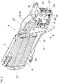
- FIG. 2 shows an embodiment of an actuator 4 with the transmission mechanism 9 in a perspective view.
- a spring device 8 is provided, which is supported on the housing 7 with a first end region 27 .
- the second end area 28 of the spring device 8 presses on a bolt 20 of a lever 17 which is mounted on the housing 7 such that it can pivot about a hinge axis 18 .
- the one-armed lever 17 has a pivot bearing 19 on which a pressure piece 16 is mounted in the form of a rotatably mounted pressure roller 29 .
- a movable adjusting part 14 preferably pivotable about an axis of rotation 11 , is arranged on the housing 7 , the adjusting part 14 being able to be connected in a movement-coupled manner to the adjusting arm 10 via a coupling device 15 .
- actuating part 14 it is also possible to form the actuating part 14 together with the actuating arm 10 in one piece.
- An actuating contour 21 is arranged or formed on the actuating part 14 , the position of which can be adjusted by an adjusting device 22 relative to the actuating part 14 , preferably relative to an axis of rotation 11 of the actuating part 14 .
- the pressure piece 16 in the form of the pressure roller 29 is pressed against the setting contour 21 by the force of the spring device 8 , the pressure piece 16 being able to roll along the setting contour 21 when the setting arm 10 or the setting part 14 is motionally coupled thereto.
- the adjustment device 22 can include an adjustment wheel 23, with the position of the adjustment contour 21 being adjustable relative to the rotatably mounted adjustment part 14 by rotating the adjustment wheel 23 by means of an actuating tool. Stepless adjustment of the position of the setting contour 21 is preferably provided. However, it is also possible to fix the setting contour 21 at two or more predetermined positions that differ from one another relative to the setting part 14 .
- the adjustment wheel 23 interacts with a spur gearing 26 of a threaded section 25, along which a bearing part 24 is adjustably mounted. By adjusting the bearing part 24, the position of the positioning contour 21, which is movement-coupled thereto, can also be adjusted.
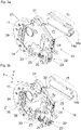
- Figure 3a 12 shows the actuating part 14, which is pivotably mounted about the axis of rotation 11, with the actuating contour 21 arranged thereon.
- the actuating part 14 has two parallel, spaced-apart components 14a and 14b.
- Figure 3b shows the control part 14 according to FIG Figure 3a without the front component 14a, so that the interaction of the adjusting wheel 23 with the spur gearing 26 of the threaded section 25 and the interaction of the bearing part 24 with the adjusting contour 21 can be seen.
- a guide element 34 with a recess 36 is connected to the setting contour 21 , a projection 35 of the adjustable bearing part 24 engaging in the recess 36 of the guide element 34 .
- the position of the actuating contour 21 relative to the axis of rotation 11 of the actuating part 14 can be adjusted in the direction of the arrow Y shown and/or in the direction of the arrow X, so that the torque curve exerted on the actuating arm 10 and/or the preload of the spring device 8 can be changed is adjustable.
- a wedge element 30 loaded by a spring element 31 is provided, which inhibits a movement of the threaded section 25 in the axial direction.
- At least one further spring element 33 is provided for the play-free mounting of the setting contour 21, which pushes the guide element 34 of the setting contour against a guide 39 ( 4 ) of the actuator 14 presses.
- the setting contour 21 forms a control curve which is eccentric relative to the axis of rotation 11 of the setting part 14 and influences the movement behavior of the movable furniture part 3 in terms of force.
- the actuating contour 21 is coupled in movement to the actuating arm 10 , with the actuating contour 21 also moving when the actuating arm 10 pivots.
- the actuating contour 21 forms a different radial distance from the axis of rotation 11 of the actuating part 14, so that a torque in the closing direction is exerted on the actuating arm 10 towards the end of the closing movement.
- the pressure piece 16 reaches an apex (this is the area of the actuating contour 21 with the greatest radial distance from the axis of rotation 11), so that the spring device 8 - after passing through this dead center position - exerts a torque on the actuating arm 10 in the opening direction .
- the torque in the opening direction can be set in such a way that the movable furniture part 3 stops automatically in any open position.
- a damper (not shown here), in particular a fluid damper, can also be used.
- FIG. 4 shows that in the Figures 3a and 3b Control part 14 shown together with the control contour 21 in an exploded view.
- the components 14a and 14b of the adjusting part 14 each have a guide 39 along which--by actuating the adjusting device 22--a corresponding guide element 34 of the adjusting contour 21 is displaceably mounted.
- the guides 39 have a linear course, so that the actuating contour 21 can be moved in the direction Y ( Figure 3b ), So transverse to the direction of action X of the spring device 8, is adjustable.
- the positioning contour 21 is in the X direction and/or in the Y direction ( Figure 3b ) adjustable, so that the preload of the spring device 8 and/or the torque curve acting on the actuating arm 10 can be adjusted in a variable manner.
- the adjusting device 22 with the adjustment wheel 23 and the threaded section 25 with the spur gearing 26 are mounted between first and second holding parts 38a and 38b, the threaded section 25 being in engagement with an internal thread 42 of the bearing part 24 and the free end section of the threaded section 25 in an opening of a third holding part 38c protrudes.
- the bearing part 24 is adjustably mounted along the threaded section 25 and engages in an opening 36 of the adjusting contour 21 with a projection 35 .
- a wedge element 30 acted upon by a spring element 31 interacts on the one hand with a counter bearing 37 and on the other hand with an end face of the threaded section 25, as a result of which the threaded section 25 is prevented from an undesired displacement in the axial direction.
- the guide element 34 of the setting contour 21 is pressed against the guide 39 of the components 14a, 14b via further spring elements 33 in the form of plastic clips, so that the setting contour 21 rests against the setting part 14 without play.
- the actuating part 14 is fastened together with the actuating contour 21 to the housing 7 of the actuating drive 4 via a sleeve 43 .
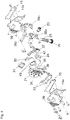
- Figures 5a-5c show the control part 14 (which is formed by the components 14b and the part 14a that is not visible here) with the control contour 21 according to a further embodiment.
- the setting contour 21 is formed here by the peripheral surface of three disks 21a, 21b, 21c, which are arranged parallel to one another.
- Threaded section 25 which can be rotated by adjusting wheel 23 is in engagement with an adjustable slide 40 .
- Ribs 41 are formed on both sides of the slide 40 and each engage in oblique slots 44 of the two outer disks 21a, 21c.
- Figure 5b shows the raised position of the discs 21a, 21b, 21c forming the adjusting contour 21 relative to the axis of rotation 11 of the component 14b.
- Figure 5c 12 shows the lowered position of the disks 21a, 21b, 21c relative to the axis of rotation 11 of the actuating part 14.
- the threaded section 25 is fixed without play in the axial direction by a spring element 31 designed as a leaf spring.
- the control part 14 comprises the components 14a and 14b, which are spaced parallel to one another by a plurality of spacers 45.
- the setting contour 21 is formed by a peripheral surface of the disks 21a, 21b, 21c.
- the components 14a, 14b each have a guide 39 for the displaceable guidance of a guide element 34 of the two outer panes 21a and 21c.
- the middle disk 21b is connected in a movement-coupled manner to the outer disks 21a, 21c.
- the threaded section 25 is in threaded engagement with a slide 40, with the slide 40 being adjustable along the threaded section 25 by turning the adjustment wheel 23, and with the discs 21a, 21b, 21c being arranged on both sides of the slide 40 via ribs 41, which in each case fit into the oblique slots 44 of the discs 21a and 21c engage, is adjustably mounted.
- Plastic profiles 46 can be provided for the low-friction guidance of the ribs 41 along the slots 44 .
- the spring element 31 designed as a leaf spring fixes the threaded section 25 or the slide 40 to the slots 44 without play, the other spring element 33 presses the guide elements 34 of the disks 21a, 21c without play against the guides 39 of the parts 14a, 14b.
- Two bearing parts 47 are provided for mounting the adjustment wheel 23 on component 14b, each of which engages in an annular groove 48 formed between the adjustment wheel 23 and the threaded section 25, so that the threaded section 25 is mounted on component 14b so that it can rotate but cannot be displaced axially.
- the adjusting wheel 23 is together with the threaded section 25 formed in one piece. If appropriate, additional gear elements can also be arranged between the adjusting wheel 23 and the threaded section 25 .
- the threaded section 25 preferably has a thread with a small pitch so that the self-locking of the slide 40 on the threaded section 25 can be improved.
- Curve A represents the (theoretical) ideal course, with opening the partial flap 3a starting from an opening angle of 0°, the force required for opening drops immediately and then approaches zero at an aperture angle of around 35°.
- the curve B represents the maximum setting of the adjusting device 22, with the torque exerted on the actuating arm 10 being the highest (i.e. for heavy furniture flaps), with the force required for opening initially increasing over a small opening angle range and then also increasing at an opening angle of around 35° goes to zero.
- Curve C shows the middle setting (i.e. for medium-heavy furniture flaps) with a torque that is reduced relative to curve B.
- curve D shows the minimum setting (ie for light furniture flaps), the torque exerted on the actuating arm 10 in the closed position being the lowest compared to curves B and C. Even if the closing forces of curves B, C, D differ slightly from one another at an opening angle of 0° of the upper partial flap 3a, the diagram shown makes it clear that the opening force curve of curves B, C, D is approximately the same.
- “Change in position” of the setting contour 21 is also understood to mean that only a section of the setting contour 21 can be adjusted by the setting device 22, which means that the position of the setting contour 21 relative to the setting part 14 also changes overall.
- This section of the setting contour 21 can be movably mounted on a carrier, for example, and can be pivoted and/or linearly adjustable relative to this carrier by the adjustment device 22 .
Landscapes
- Engineering & Computer Science (AREA)
- General Engineering & Computer Science (AREA)
- Mechanical Engineering (AREA)
- Closing And Opening Devices For Wings, And Checks For Wings (AREA)
- Legs For Furniture In General (AREA)
- Power-Operated Mechanisms For Wings (AREA)
Description
- Die vorliegende Erfindung bezieht sich auf einen Stellantrieb zum Bewegen eines bewegbaren Möbelteiles, umfassend:
- zumindest einen um eine Drehachse schwenkbar gelagerten Stellarm zum Bewegen des bewegbaren Möbelteiles,
- eine Federvorrichtung zur Kraftbeaufschlagung des Stellarmes,
- einen Übertragungsmechanismus zum Übertragen einer Kraft von der Federvorrichtung auf den Stellarm, wobei der Übertragungsmechanismus ein mit dem Stellarm bewegungsgekoppeltes Stellteil, eine am Stellteil angeordnete Stellkontur und ein von der Federvorrichtung belastetes Druckstück aufweist, wobei das Druckstück bei einer Bewegung des Stellarmes entlang der Stellkontur verfahrbar ist.
- Im Weiteren betrifft die Erfindung eine Anordnung mit einem bewegbaren Möbelteil und mit einem Stellantrieb der zu beschreibenden Art.
- In der
WO 2006/005086 A1 der Anmelderin ist ein Stellantrieb zum Bewegen von Möbelklappen beschrieben, wobei die Kraft einer Federvorrichtung über einen Übertragungsmechanismus auf einen schwenkbar gelagerten Stellarm übertragbar ist. Der Übertragungsmechanismus umfasst dabei einen von der Federvorrichtung belasteten Zwischenhebel, der über eine Druckrolle und eine Stellkontur den Stellarm verschwenkt. Zur Einstellung der Federkraft ist eine Befestigungsstelle der Federvorrichtung am Zwischenhebel entlang einer Gewindespindel verstellbar gelagert. Hierfür ist ein entsprechend langer Verstellweg vorzusehen, der den Bauraum des Stellantriebes erhöht. - Aufgabe der vorliegenden Erfindung ist es, einen Stellantrieb der eingangs erwähnten Gattung mit einer kompakteren Bauweise anzugeben.
- Dies wird erfindungsgemäß durch die Merkmale des Patentanspruchs 1 gelöst. Weitere vorteilhafte Ausgestaltungen der Erfindung sind in den abhängigen Unteransprüchen angegeben.
- Gemäß der Erfindung ist eine Einstellvorrichtung vorgesehen, durch welche die Lage der Stellkontur relativ zum Stellteil einstellbar ist.
- Mit anderen Worten weist der Stellantrieb ein bewegliches Stellteil auf, welches sich bei einer Bewegung des Stellarmes mit diesem mitbewegt. An diesem Stellteil ist eine Stellkontur angeordnet oder ausgebildet, wobei die Stellkontur durch eine manuelle Betätigung der Einstellvorrichtung relativ zum Stellteil, vorzugsweise relativ zu einer Drehachse des Stellteiles, einstellbar ist.
- Der Vorteil dieser Konstruktion liegt zunächst in einem reduzierten Verstellweg, da durch die Einstellung der Stellkontur relativ zum Stellteil direkt auf die Federvorspannung und/oder auf den Drehmomentverlauf des Stellarmes Einfluss genommen wird. Auf diese Weise kann beispielsweise auf die Anordnung von relativ langen Gewindespindeln, durch die eine Befestigungsstelle der Federvorrichtung an einem Zwischenhebel relativ zur Drehachse dieses Zwischenhebels verstellbar ist, verzichtet werden. Der erforderliche Einstellweg kann daher - bei gleich abzudeckendem Kraftbereich im Vergleich zum Stand der Technik - entsprechend verringert werden, wobei besonders kompakte Bauformen des Stellantriebes möglich sind.
- Durch eine durch die Einstellvorrichtung herbeigeführte - vorzugsweise stufenlose - Änderung der Lage der Stellkontur relativ zum Stellteil ist auch das auf den Stellarm und damit das auf das bewegbare Möbelteil ausgeübte Drehmoment und/oder der Drehmomentverlauf veränderbar einstellbar. Somit ist der Stellantrieb für verschiedene Gewichte, Größen und Formen von Möbelklappen, insbesondere auch für Faltklappen mit gelenkig miteinander verbundenen Teilklappen, gleichermaßen verwendbar.
- Gemäß einem Ausführungsbeispiel kann vorgesehen sein, dass die Federvorrichtung austauschbar am Stellantrieb gelagert ist, sodass Federvorrichtungen mit unterschiedlichen Leistungsfaktoren wahlweise an ein und demselben Stellantrieb zu befestigen sind. Eine Person kann also im Werk oder auch vor Ort aus einem Set von Federvorrichtungen jenen Leistungsfaktor auswählen, der mit dem jeweiligen Gewicht der Möbelklappe und mit der Höhe des Möbelkorpus korrespondiert. Nach erfolgter Auswahl der Federvorrichtung kann durch Betätigung der Einstellvorrichtung eine präzise Krafteinstellung bzw. Feinjustierung durchgeführt werden, die exakt auf das jeweilige Gewicht der Klappe abgestimmt ist.
- Gemäß einem Ausführungsbeispiel wandelt die Einstellvorrichtung eine durch eine Person herbeigeführte Drehbewegung eines Verstellrades in eine Längsbewegung der Stellkontur um. Die Einstellvorrichtung ist zweckmäßigerweise selbsthemmend ausgebildet, sodass also die vorgenommene Einstellung ohne weiteres Zutun in jeder einmal eingestellten Position verbleibt. Die Einstellvorrichtung kann beispielsweise ein Schneckengetriebe, eine mit einer Verzahnung zusammenwirkende spiralförmige Kulisse, ein mit einer Zahnstange zusammenwirkendes Zahnrad oder auch einen selbsthemmend ausgebildeten Exzenter aufweisen.
- Weitere Einzelheiten und Vorteile der vorliegenden Erfindung ergeben sich anhand der in den Figuren gezeigten Ausführungsbeispiele. Dabei zeigt bzw. zeigen:
- Fig. 1a, 1b
- ein Möbel mit einem Möbelkorpus und einem relativ dazu bewegbaren Möbelteil in einer perspektivischen Darstellung sowie der am Möbelkorpus befestigte Stellantrieb in einer Seitenansicht,
- Fig. 2
- ein Ausführungsbeispiel eines Stellantriebes in einer perspektivischen Ansicht,
- Fig. 3a, 3b
- das Stellteil mit der daran angeordneten Stellkontur in zwei verschiedenen Ansichten,
- Fig. 4
- den Stellantrieb in einer Explosionsdarstellung,
- Fig. 5a-5c
- verschiedene Ansichten eines Stellteiles mit der Stellkontur gemäß einer weiteren Ausführungsform,
- Fig. 6
- die Ausführungsform gemäß den
Fig. 5a-5c in einer Explosionsdarstellung, - Fig. 7
- ein Diagramm der Öffnungskraftverläufe mit unterschiedlich eingestellten Lagen der Stellkontur aufgetragen über den Öffnungswinkel der oberen Teilklappe gemäß
Fig. 1a, 1b -
Fig. 1a zeigt ein Möbel 1 mit einem Möbelkorpus 2 und einem bewegbaren Möbelteil 3 in einer perspektivischen Ansicht. Das bewegbare Möbelteil 3 ist in der gezeigten Figur als zweiteilige Hochfaltklappe mit zwei Teilklappen 3a und 3b ausgebildet, wobei die obere Teilklappe 3a über erste Scharniere 5a (Fig. 1b ) schwenkbar mit dem Schrankdeckel 6 und die untere Teilklappe 3b über zweite Scharniere 5b gelenkig mit der oberen Teilklappe 3a verbunden ist. Zum Bewegen des bewegbaren Möbelteiles 3 ist zumindest ein Stellantrieb 4 am Möbelkorpus 2 montiert, wobei das bewegbare Möbelteil 3 zwischen einer Schließstellung (in der die beiden Teilklappen 3a, 3b in einer gemeinsamen vertikalen Ebene liegen und dabei den Möbelkorpus 2 verschließen) und einer Öffnungsstellung (in der die Teilklappen 3a, 3b eine wie inFig. 1b gezeigte winkelige Stellung relativ zueinander einnehmen) bewegbar gelagert ist. -
Fig. 1b zeigt den am Möbelkorpus 2 befestigten Stellantrieb 4 in einer Seitenansicht, wobei zur Bewegungsunterstützung des bewegbaren Möbelteiles 3 in einem Gehäuse 7 eine Federvorrichtung 8 angeordnet ist. In der gezeigten Figur ist die Federvorrichtung 8 als Federpaket mit mehreren parallel geschalteten Schraubenfedern, vorzugsweise Druckfedern, ausgebildet. Die Kraft der Federvorrichtung 8 ist über einen Übertragungsmechanismus 9 auf einen Stellarm 10 übertragbar, welcher einerseits um eine Drehachse 11 schwenkbar am Gehäuse 7 gelagert und andererseits über eine Gelenkachse 13 schwenkbar mit einem an der unteren Teilklappe 3b zu befestigenden Beschlagteil 12 verbunden ist. Der Stellantrieb 4 ist aber gleichermaßen auch für einteilige Möbelklappen, insbesondere für so genannte Hochschwenkklappen (wobei die Klappe über den Möbelkorpus 2 hinweg verschwenkt wird), Hochklappen (wobei die Klappe um eine horizontale Achse schwenkbar am Möbelkorpus 2 gelagert ist) sowie Hochliftklappen (wobei die Klappe vertikal angehoben wird) einsetzbar. -
Fig. 2 zeigt ein Ausführungsbeispiel eines Stellantriebes 4 mit dem Übertragungsmechanismus 9 in einer perspektivischen Ansicht. Zur Kraftbeaufschlagung des Stellarmes 10 (Fig. 1b ) ist eine Federvorrichtung 8 vorgesehen, welche sich mit einem ersten Endbereich 27 am Gehäuse 7 abstützt. Der zweite Endbereich 28 der Federvorrichtung 8 drückt auf einen Bolzen 20 eines Hebels 17, der um eine Gelenkachse 18 schwenkbar am Gehäuse 7 gelagert ist. - Zum werkzeuglosen Austausch bzw. Ersatz der Federvorrichtung 8 mit einem unterschiedlichen Leistungsfaktor wird der zweite Endbereich 28 der Federvorrichtung 8 durch manuelle Druckausübung entgegen der Federkraft in Richtung zum ersten Endbereich 27 gedrückt, sodass die Federvorrichtung 8 komprimiert und die lose Verbindung zwischen dem zweiten Endbereich 28 und dem Bolzen 20 lösbar ist. Der einarmige Hebel 17 weist ein Drehlager 19 auf, an dem ein Druckstück 16 in Form einer drehbar gelagerten Druckrolle 29 gelagert ist. Am Gehäuse 7 ist ein beweglicher, vorzugsweise um eine Drehachse 11 schwenkbarer, Stellteil 14 angeordnet, wobei das Stellteil 14 mit dem Stellarm 10 über eine Kupplungsvorrichtung 15 bewegungsgekoppelt verbindbar ist. Alternativ ist es auch möglich, das Stellteil 14 zusammen mit dem Stellarm 10 einstückig auszubilden. Am Stellteil 14 ist eine Stellkontur 21 angeordnet oder ausgebildet, deren Lage durch eine Einstellvorrichtung 22 relativ zum Stellteil 14, vorzugsweise relativ zu einer Drehachse 11 des Stellteiles 14, einstellbar ist. Das Druckstück 16 in Form der Druckrolle 29 wird durch die Kraft der Federvorrichtung 8 gegen die Stellkontur 21 gedrückt, wobei das Druckstück 16 bei einer Bewegung des Stellarmes 10 bzw. des damit bewegungsgekoppelten Stellteiles 14 entlang der Stellkontur 21 abrollbar ist.
- Die Einstellvorrichtung 22 kann ein Verstellrad 23 umfassen, wobei durch Drehung des Verstellrades 23 mittels Betätigungswerkzeug die Lage der Stellkontur 21 relativ zum drehbar gelagerten Stellteil 14 einstellbar ist. Vorzugsweise ist eine stufenlose Einstellung der Lage der Stellkontur 21 vorgesehen. Es ist aber auch möglich, die Stellkontur 21 an zwei oder mehreren vorgegebenen und voneinander abweichenden Positionen relativ zum Stellteil 14 festzulegen. Im gezeigten Ausführungsbeispiel wirkt das Verstellrad 23 mit einer Stirnverzahnung 26 eines Gewindeabschnittes 25 zusammen, entlang dem ein Lagerteil 24 verstellbar gelagert ist. Durch eine Verstellung des Lagerteiles 24 ist auch die Lage der damit bewegungsgekoppelten Stellkontur 21 einstellbar.
-
Fig. 3a zeigt den um die Drehachse 11 schwenkbar gelagerten Stellteil 14 mit der daran angeordneten Stellkontur 21. Das Stellteil 14 weist im gezeigten Ausführungsbeispiel zwei voneinander parallel beabstandete Bauteile 14a und 14b auf. Durch eine durch eine Person herbeigeführte Verdrehung des Verstellrades 23 wird der Lagerteil 24 entlang des Gewindeabschnittes 25 bewegt, wodurch auch die Lage der Stellkontur 21 relativ zum Stellteil 14 einstellbar ist. -
Fig. 3b zeigt das Stellteil 14 gemäßFig. 3a ohne das vordere Bauteil 14a, sodass das Zusammenwirken des Verstellrades 23 mit der Stirnverzahnung 26 des Gewindeabschnittes 25 sowie das Zusammenwirken des Lagerteiles 24 mit der Stellkontur 21 ersichtlich ist. Mit der Stellkontur 21 ist ein Führungselement 34 mit einer Ausnehmung 36 verbunden, wobei ein Vorsprung 35 des verstellbaren Lagerteiles 24 in die Ausnehmung 36 des Führungselementes 34 eingreift. Auf diese Weise ist die Lage der Stellkontur 21 relativ zur Drehachse 11 des Stellteiles 14 in Richtung des eingezeichneten Pfeils Y und/oder in Richtung des Pfeils X einstellbar, sodass also der auf den Stellarm 10 ausgeübte Drehmomentverlauf und/oder die Vorspannung der Federvorrichtung 8 veränderbar einstellbar ist. Zur spielfreien Lagerung des Gewindeabschnitts 25 ist ein von einem Federelement 31 belastetes Keilelement 30 vorgesehen, das eine Bewegung des Gewindeabschnitts 25 in axialer Richtung hemmt. Zur spielfreien Lagerung der Stellkontur 21 ist zumindest ein weiteres Federelement 33 vorgesehen, welches das Führungselement 34 der Stellkontur gegen eine Führung 39 (Fig. 4 ) des Stellteiles 14 drückt. - Die Stellkontur 21 bildet eine relativ zur Drehachse 11 des Stellteiles 14 exzentrische, das Bewegungsverhalten des bewegbaren Möbelteiles 3 kräftemäßig beeinflussende Steuerkurve aus. Die Stellkontur 21 ist mit dem Stellarm 10 bewegungsgekoppelt, wobei sich bei einer Schwenkbewegung des Stellarmes 10 auch die Stellkontur 21 mitbewegt. Die Stellkontur 21 bildet einen unterschiedlich radialen Abstand zur Drehachse 11 des Stellteiles 14 aus, sodass auf den Stellarm 10 gegen Ende der Schließbewegung ein Drehmoment in Schließrichtung ausgeübt wird. Bei der Öffnungsbewegung des Stellarmes 10 gelangt das Druckstück 16 auf einen Scheitelpunkt (das ist jener Bereich der Stellkontur 21 mit dem größten Radialabstand zur Drehachse 11), sodass die Federvorrichtung 8 - nach dem Durchlauf dieser Totpunktlage - auf den Stellarm 10 ein Drehmoment in Öffnungsrichtung ausübt. Das Drehmoment in Öffnungsrichtung kann so eingestellt werden, dass das bewegbare Möbelteil 3 in jeder Offenstellung selbsttätig stehen bleibt. Zur Dämpfung der Schließ- und/oder Öffnungsbewegung des Stellarmes 10 kann auch ein (hier nicht gezeigter) Dämpfer, insbesondere ein Fluiddämpfer, eingesetzt werden.
-
Fig. 4 zeigt das in denFig. 3a und Fig. 3b gezeigte Stellteil 14 zusammen mit der Stellkontur 21 in einer Explosionsdarstellung. Die Bauteile 14a und 14b des Stellteiles 14 weisen jeweils eine Führung 39 auf, entlang der - durch Betätigung der Einstellvorrichtung 22 - ein korrespondierendes Führungselement 34 der Stellkontur 21 verschiebbar gelagert ist. Im gezeigten Ausführungsbeispiel weisen die Führungen 39 einen linearen Verlauf auf, sodass also die Stellkontur 21 in Richtung Y (Fig. 3b ), also quer zur Wirkrichtung X der Federvorrichtung 8, verstellbar ist. Durch die jeweilige Form und Größe der Führung 39 (beispielsweise durch einen bogenförmigen Verlauf der Führung 39) ist die Stellkontur 21 in Richtung X und/oder in Richtung Y (Fig. 3b ) verstellbar, sodass die Vorspannung der Federvorrichtung 8 und/oder der auf den Stellarm 10 wirkende Drehmomentverlauf veränderbar einstellbar ist. Die Einstellvorrichtung 22 mit dem Verstellrad 23 sowie der Gewindeabschnitt 25 mit der Stirnverzahnung 26 lagern zwischen ersten und zweiten Halteteilen 38a und 38b, wobei der Gewindeabschnitt 25 in Eingriff mit einem Innengewinde 42 des Lagerteiles 24 steht und wobei der freie Endabschnitt des Gewindeabschnitts 25 in eine Öffnung eines dritten Halteteiles 38c hineinragt. Entlang des Gewindeabschnitts 25 ist der Lagerteil 24 verstellbar gelagert, der mit einem Vorsprung 35 in eine Öffnung 36 der Stellkontur 21 eingreift. Ein durch ein Federelement 31 beaufschlagtes Keilelement 30 wirkt einerseits mit einem Gegenlager 37, andererseits mit einer Stirnfläche des Gewindeabschnitts 25 zusammen, wodurch der Gewindeabschnitt 25 an einer unerwünschten Verschiebung in axialer Richtung gehemmt ist. Über weitere Federelemente 33 in Form von Kunststoffspangen wird das Führungselement 34 der Stellkontur 21 gegen die Führung 39 der Bauteile 14a, 14b gedrückt, sodass die Stellkontur 21 am Stellteil 14 spielfrei anliegt. Über eine Hülse 43 ist das Stellteil 14 zusammen mit der Stellkontur 21 am Gehäuse 7 des Stellantriebes 4 befestigt. -
Fig. 5a-5c zeigen das Stellteil 14 (welches durch die Bauteile 14b und dem hier nicht ersichtlichen Teil 14a gebildet ist) mit der Stellkontur 21 gemäß einer weiteren Ausführungsform. Die Stellkontur 21 wird hierbei von der Umfangsfläche dreier Scheiben 21a, 21b, 21c gebildet, welche parallel zueinander angeordnet sind. Der durch das Verstellrad 23 verdrehbare Gewindeabschnitt 25 steht dabei mit einem verstellbaren Schieber 40 in Eingriff. Am Schieber 40 sind beidseitig Rippen 41 ausgebildet, die jeweils in schrägen Schlitzen 44 der beiden äußeren Scheiben 21a, 21c eingreifen. Durch Verdrehen des Verstellrades 23 mittels Betätigungswerkzeug sind alle drei Scheiben 21a, 21b, 21c gemeinsam im Paket über die Rippen 41 relativ zur Drehachse 11 anhebbar und absenkbar.Fig. 5b zeigt die angehobene Stellung der die Stellkontur 21 bildenden Scheiben 21a, 21b, 21c relativ zur Drehachse 11 des Bauteils 14b.Fig. 5c zeigt hingegen die abgesenkte Lage der Scheiben 21a, 21b, 21c relativ zur Drehachse 11 des Stellteiles 14. Durch ein als Blattfeder ausgebildetes Federelement 31 ist der Gewindeabschnitt 25 in axialer Richtung spielfrei festgelegt. -
Fig. 6 zeigt die Ausführungsform gemäß denFig. 5a-5c in einer Explosionsdarstellung. Das Stellteil 14 umfasst die Bauteile 14a und 14b, die durch mehrere Distanzhalter 45 voneinander parallel beabstandet sind. Die Stellkontur 21 wird durch eine Umfangsfläche der Scheiben 21a, 21b, 21c gebildet. Die Bauteile 14a, 14b weisen jeweils eine Führung 39 zur verschiebbaren Führung eines Führungselementes 34 der beiden äußeren Scheiben 21a und 21c auf. Die mittlere Scheibe 21b ist mit den äußeren Scheiben 21a, 21c bewegungsgekoppelt verbunden. Der Gewindeabschnitt 25 steht mit einem Schieber 40 in Gewindeeingriff, wobei durch Verdrehen des Verstellrades 23 der Schieber 40 entlang des Gewindeabschnittes 25 verstellbar ist und wobei die Scheiben 21a, 21b, 21c über beidseitig am Schieber 40 angeordnete Rippen 41, welche jeweils in die schrägen Schlitze 44 der Scheiben 21a und 21c eingreifen, verstellbar gelagert ist. Zur reibungsarmen Führung der Rippen 41 entlang der Schlitze 44 können Kunststoffprofile 46 vorgesehen werden. Durch das als Blattfeder ausgebildete Federelement 31 ist der Gewindeabschnitt 25 bzw. der Schieber 40 an den Schlitzen 44 spielfrei festgelegt, das andere Federelement 33 drückt die Führungselemente 34 der Scheiben 21a, 21c spielfrei gegen die Führungen 39 des Teile 14a, 14b. Zur Lagerung des Verstellrades 23 am Bauteil 14b sind zwei Lagerteile 47 vorgesehen, die jeweils in eine zwischen dem Verstellrad 23 und dem Gewindeabschnitt 25 gebildete Ringnut 48 eingreifen, sodass der Gewindeabschnitt 25 am Bauteil 14b drehbar, jedoch axial unverschiebbar gelagert ist. Gemäß dem gezeigten Ausführungsbeispiel ist das Verstellrad 23 zusammen mit dem Gewindeabschnitt 25 einstückig ausgebildet. Falls zweckmäßig, können zwischen dem Verstellrad 23 und dem Gewindeabschnitt 25 auch zusätzliche Getriebeelemente angeordnet werden. Der Gewindeabschnitt 25 weist vorzugsweise ein Gewinde mit geringer Steigung auf, damit die Selbsthemmung des Schiebers 40 am Gewindeabschnitt 25 verbessert werden kann. -
Fig. 7 zeigt einen möglichen Verlauf der Öffnungskraft, Kraft F in Newton [N], der oberen Teilklappe 3a (Fig. 1 ) aufgetragen über dem Öffnungswinkel, in Grad [deg], bei unterschiedlichen Einstellungen der Stellkontur 21 relativ zum Stellteil 14. Die Kurve A stellt den (theoretischen) Idealverlauf dar, wobei beim Öffnen der Teilklappe 3a ausgehend von 0° Öffnungswinkel die erforderliche Kraft zum Öffnen unmittelbar absinkt und anschließend bei etwa 35° Öffnungswinkel gegen Null geht. Die Kurve B stellt die Maximaleinstellung der Einstellvorrichtung 22 dar, wobei also das auf den Stellarm 10 ausgeübte Drehmoment am höchsten ist (also für schwere Möbelklappen), wobei die zum Öffnen erforderliche Kraft zunächst über eine kleinen Öffnungswinkelbereich ansteigt und anschließend bei etwa 35° Öffnungswinkel ebenfalls gegen Null geht. Die Kurve C zeigt die mittlere Einstellung (also für mittelschwere Möbelklappen) mit einem relativ zur Kurve B reduzierten Drehmoment. Die Kurve D zeigt schließlich die Minimaleinstellung (also für leichte Möbelklappen), wobei das in der Schließstellung ausgeübte Drehmoment auf den Stellarm 10 im Vergleich zu den Kurven B und C am geringsten ist. Auch wenn die Zuhaltekräfte der Kurven B, C, D bei 0° Öffnungswinkel der oberen Teilklappe 3a geringfügig voneinander abweichen, so wird anhand des gezeigten Diagramms deutlich, dass unabhängig von der eingestellten Lage der Stellkontur 21 relativ zum Stellteil 14 der Öffnungskraftverlauf der Kurven B, C, D annähernd gleich ist. - Unter "Lageänderung" der Stellkontur 21 sei auch die Maßnahme verstanden, dass nur ein Teilabschnitt der Stellkontur 21 durch die Einstellvorrichtung 22 verstellbar ist, womit sich insgesamt auch die Lage der Stellkontur 21 relativ zum Stellteil 14 ändert. Dieser Teilabschnitt der Stellkontur 21 kann beispielsweise an einem Träger beweglich gelagert und durch die Einstellvorrichtung 22 relativ zu diesem Träger schwenkbar und/oder linear verstellbar gelagert sein.
Claims (13)
- Stellantrieb (4) zum Bewegen eines bewegbaren Möbelteiles (3), umfassend:- zumindest einen um eine Drehachse (11) schwenkbar gelagerten Stellarm (10) zum Bewegen des bewegbaren Möbelteiles (3),- eine Federvorrichtung (8) zur Kraftbeaufschlagung des Stellarmes (10),- einen Übertragungsmechanismus (9) zum Übertragen einer Kraft von der Federvorrichtung (8) auf den Stellarm (10), wobei der Übertragungsmechanismus (9) ein mit dem Stellarm (10) bewegungsgekoppeltes Stellteil (14), eine am Stellteil (14) angeordnete Stellkontur (21) und ein von der Federvorrichtung (8) belastetes Druckstück (16) aufweist, wobei das Druckstück (16) bei einer Bewegung des Stellarmes (10) entlang der Stellkontur (21) verfahrbar ist, wobei das Druckstück (16) als drehbar gelagerte Druckrolle (29) ausgebildet ist,dadurch gekennzeichnet, dass eine Einstellvorrichtung (22) vorgesehen ist, durch welche die Lage der Stellkontur (21) relativ zum Stellteil (14) einstellbar ist.
- Stellantrieb nach Anspruch 1, dadurch gekennzeichnet, dass die Einstellvorrichtung (22) selbsthemmend ausgebildet ist.
- Stellantrieb nach Anspruch 1 oder 2, dadurch gekennzeichnet, dass die Lage der Stellkontur (21) durch die Einstellvorrichtung (22) stufenlos einstellbar ist.
- Stellantrieb nach einem der Ansprüche 1 bis 3, dadurch gekennzeichnet, dass die Einstellvorrichtung (22) eine durch eine Person herbeigeführte Drehbewegung eines Verstellrades (23) in eine Längsbewegung der Stellkontur (21) umwandelt.
- Stellantrieb nach Anspruch 4, dadurch gekennzeichnet, dass durch Verdrehen des Verstellrades (23) ein Lagerteil (24) antreibbar ist, welches entlang eines Gewindeabschnittes (25) verstellbar gelagert ist, wobei die Stellkontur (21) mit dem Lagerteil (24) bewegungsgekoppelt verbunden ist.
- Stellantrieb nach Anspruch 5, dadurch gekennzeichnet, dass der Gewindeabschnitt (25) in axialer Richtung durch ein durch ein Federelement (31) belastetes Keilelement (30) spielfrei festgelegt ist.
- Stellantrieb nach einem der Ansprüche 1 bis 6, dadurch gekennzeichnet, dass das Stellteil (14) eine Führung (39) aufweist, entlang der die Stellkontur (21) verstellbar gelagert ist, wobei ein mit der Stellkontur (21) verbundenes Führungselement (34) entlang dieser Führung (39) verstellbar gelagert ist.
- Stellantrieb nach Anspruch 7, dadurch gekennzeichnet, dass zumindest ein weiteres Federelement (33) vorgesehen ist, welches das Führungselement (34) der Stellkontur (21) gegen die Führung (39) des Stellteiles (14) drückt.
- Stellantrieb nach einem der Ansprüche 1 bis 8, dadurch gekennzeichnet, dass durch eine Betätigung der Einstellvorrichtung (22) die Vorspannung der Federvorrichtung (8) und/oder der auf den Stellarm (10) wirkende Drehmomentverlauf veränderbar einstellbar ist.
- Stellantrieb nach einem der Ansprüche 1 bis 9, dadurch gekennzeichnet, dass die Federvorrichtung (8) zumindest eine, vorzugsweise als Druckfeder ausgebildete, Schraubenfeder umfasst.
- Stellantrieb nach einem der Ansprüche 1 bis 10, dadurch gekennzeichnet, dass das Stellteil (14) zwei oder mehrere miteinander verbundene Bauteile (14a, 14b) aufweist.
- Stellantrieb nach einem der Ansprüche 1 bis 11, dadurch gekennzeichnet, dass die Stellkontur (21) zwei oder mehrere miteinander verbundene Scheiben (21a, 21b, 21c) aufweist.
- Anordnung mit einem bewegbaren Möbelteil (3) und mit einem Stellantrieb (4) nach einem der Ansprüche 1 bis 12 zum Bewegen des bewegbaren Möbelteiles (3).
Applications Claiming Priority (2)
| Application Number | Priority Date | Filing Date | Title |
|---|---|---|---|
| ATA842/2014A AT515661B1 (de) | 2014-11-21 | 2014-11-21 | Stellantrieb für bewegbare Möbelteile |
| PCT/AT2015/000124 WO2016077851A1 (de) | 2014-11-21 | 2015-09-28 | Stellantrieb für bewegbare möbelteile |
Publications (3)
| Publication Number | Publication Date |
|---|---|
| EP3221538A1 EP3221538A1 (de) | 2017-09-27 |
| EP3221538B1 EP3221538B1 (de) | 2018-03-07 |
| EP3221538B2 true EP3221538B2 (de) | 2022-07-20 |
Family
ID=54329341
Family Applications (1)
| Application Number | Title | Priority Date | Filing Date |
|---|---|---|---|
| EP15781288.4A Active EP3221538B2 (de) | 2014-11-21 | 2015-09-28 | Stellantrieb für bewegbare möbelteile |
Country Status (8)
| Country | Link |
|---|---|
| US (1) | US10487554B2 (de) |
| EP (1) | EP3221538B2 (de) |
| JP (1) | JP6423093B2 (de) |
| CN (1) | CN107075892B (de) |
| AT (1) | AT515661B1 (de) |
| HU (1) | HUE037752T2 (de) |
| TR (1) | TR201807674T4 (de) |
| WO (1) | WO2016077851A1 (de) |
Families Citing this family (20)
| Publication number | Priority date | Publication date | Assignee | Title |
|---|---|---|---|---|
| AT16616U1 (de) * | 2013-03-13 | 2020-02-15 | Blum Gmbh Julius | Befestigungsvorrichtung für einen Möbelbeschlag |
| AT517243B1 (de) * | 2015-06-09 | 2017-02-15 | Blum Gmbh Julius | Ausstoßvorrichtung für ein bewegbares Möbelteil |
| AT16333U1 (de) * | 2016-03-11 | 2019-07-15 | Blum Gmbh Julius | Stellantrieb zum Antrieb eines bewegbar gelagerten Möbelteils |
| AT518535B1 (de) * | 2016-04-28 | 2017-11-15 | Blum Gmbh Julius | Möbelantrieb |
| WO2018192819A1 (de) * | 2017-04-18 | 2018-10-25 | Hettich-Oni Gmbh & Co. Kg | Möbelplatte mit einem klappenbeschlag und möbelkorpus sowie möbel mit einer derartigen möbelplatte |
| DE102017108197B4 (de) | 2017-04-18 | 2025-07-17 | Hettich-Oni Gmbh & Co. Kg | Möbel |
| TR201818259A2 (tr) | 2018-11-30 | 2020-06-22 | Samet Kalip Ve Madeni Esya Sanayi Ve Ticaret Anonim Sirketi | Yukarı Yönde Açılan Dolap Kapakları İçin Bir Mobilya Menteşesi |
| AT522287A1 (de) * | 2019-03-20 | 2020-10-15 | Blum Gmbh Julius | Federführung |
| AT522446B1 (de) * | 2019-05-17 | 2020-11-15 | Blum Gmbh Julius | Möbelantrieb |
| AT522458B1 (de) * | 2019-05-17 | 2020-11-15 | Blum Gmbh Julius | Möbelbeschlag |
| AT522656B1 (de) * | 2019-05-17 | 2025-04-15 | Blum Gmbh Julius | Möbelantrieb |
| AT522746B1 (de) * | 2019-07-10 | 2025-03-15 | Blum Gmbh Julius | Möbelbeschlag |
| AT524383A1 (de) * | 2020-10-22 | 2022-05-15 | Blum Gmbh Julius | Möbelbeschlag |
| AT524338B1 (de) * | 2020-10-22 | 2023-08-15 | Blum Gmbh Julius | Möbelantrieb |
| AT524381B1 (de) * | 2020-10-22 | 2022-07-15 | Blum Gmbh Julius | Möbelantrieb zum Bewegen eines relativ zu einem Möbelkorpus bewegbar gelagerten Möbelteiles |
| AT524337B1 (de) * | 2020-10-22 | 2023-07-15 | Blum Gmbh Julius | Möbelantrieb |
| AT524391A1 (de) * | 2020-11-12 | 2022-05-15 | Blum Gmbh Julius | Möbelantrieb zum Bewegen eines relativ zu einem Möbelkorpus bewegbar gelagerten Möbelteiles |
| AT524704B1 (de) * | 2021-01-27 | 2022-10-15 | Blum Gmbh Julius | Möbelantrieb |
| DE102021124927A1 (de) | 2021-09-27 | 2023-03-30 | ambigence GmbH & Co. KG | Möbelkomponente |
| DK202470169A1 (en) * | 2024-06-18 | 2026-01-08 | Vkr Holding As | Roof window with an adjustment system comprising a worm gear |
Family Cites Families (22)
| Publication number | Priority date | Publication date | Assignee | Title |
|---|---|---|---|---|
| US2824466A (en) | 1953-07-17 | 1958-02-25 | Polarad Electronics Corp | Adjustable periphery cam |
| US3680406A (en) * | 1971-06-07 | 1972-08-01 | Us Army | Flexible cams |
| US3792627A (en) * | 1973-06-21 | 1974-02-19 | Survival Technology | Adjustable cam assembly |
| DE3214845A1 (de) | 1982-04-21 | 1983-11-03 | Mannesmann Rexroth GmbH, 8770 Lohr | Vorrichtung zum betaetigen eines schiebekoerpers, insbesondere des kolbenschiebers eines wegeventils |
| JPS5917005U (ja) * | 1982-07-22 | 1984-02-01 | シャープ株式会社 | 可動体の開閉制御装置 |
| DE4012204A1 (de) * | 1990-04-14 | 1991-10-17 | Sipra Patent Beteiligung | Schlossanordnung fuer strickmaschinen, insbesondere rundstrickmaschinen |
| GB2338027B (en) * | 1998-06-06 | 2002-09-11 | Norfrost Ltd | Hinge |
| DE10019337C2 (de) | 2000-04-19 | 2003-07-31 | Hettich Hetal Werke | Klappenhalter |
| EP1154109B1 (de) * | 2000-05-12 | 2009-01-07 | Antonio Giovannetti | Federantriebsvorrichtung für Türen, mit regelbarem Hebelarm der Feder |
| DE10145856B4 (de) * | 2001-09-17 | 2005-09-08 | Huwil-Werke Gmbh Möbelschloss- Und Beschlagfabriken | Faltdeckel |
| DE10223026C5 (de) | 2002-05-22 | 2007-11-08 | Huwil-Werke Gmbh Möbelschloss- Und Beschlagfabriken | Deckelsteller |
| DE10323698B3 (de) | 2003-05-22 | 2005-02-10 | Huwil-Werke Gmbh Möbelschloss- Und Beschlagfabriken | Deckelsteller |
| DE102004019785B4 (de) * | 2004-04-23 | 2006-04-27 | Hetal-Werke Franz Hettich Gmbh & Co. Kg | Klappenbeschlag |
| CN1985064B (zh) * | 2004-07-14 | 2011-08-24 | 尤利乌斯·布卢姆有限公司 | 可旋转支承的操纵臂的操纵机构 |
| AT502941B1 (de) * | 2004-12-28 | 2011-05-15 | Blum Gmbh Julius | Stellantrieb zum antrieb einer klappe eines möbels |
| DE502007002184D1 (de) * | 2006-03-28 | 2010-01-14 | Hettich Hetal Werke | Klappenhalter für eine möbelklappe |
| DE102006014493A1 (de) * | 2006-03-29 | 2007-10-11 | Hetal-Werke Franz Hettich Gmbh & Co. Kg | Klappenhalter für eine Möbelklappe |
| DE102007026876A1 (de) | 2007-05-07 | 2008-11-13 | Heinrich J. Kesseböhmer KG | Möbelbeschlag |
| AT505879A1 (de) * | 2007-09-28 | 2009-04-15 | Blum Gmbh Julius | Stellmechanismus fur einen schwenkbar gelagerten stellarm |
| AT15281U1 (de) * | 2008-11-06 | 2017-04-15 | Blum Gmbh Julius | Montagesicherung für einen Stellantrieb einer Möbelklappe |
| AT513387B1 (de) * | 2013-02-08 | 2014-04-15 | Blum Gmbh Julius | Stellantrieb zum Bewegen eines bewegbaren Möbelteiles |
| AT515492B1 (de) * | 2014-03-14 | 2020-01-15 | Blum Gmbh Julius | Stellantrieb für Möbelklappen |
-
2014
- 2014-11-21 AT ATA842/2014A patent/AT515661B1/de active
-
2015
- 2015-09-28 HU HUE15781288A patent/HUE037752T2/hu unknown
- 2015-09-28 CN CN201580056115.5A patent/CN107075892B/zh active Active
- 2015-09-28 WO PCT/AT2015/000124 patent/WO2016077851A1/de not_active Ceased
- 2015-09-28 EP EP15781288.4A patent/EP3221538B2/de active Active
- 2015-09-28 TR TR2018/07674T patent/TR201807674T4/tr unknown
- 2015-09-28 JP JP2017522864A patent/JP6423093B2/ja active Active
-
2017
- 2017-03-30 US US15/474,452 patent/US10487554B2/en active Active
Also Published As
| Publication number | Publication date |
|---|---|
| HUE037752T2 (hu) | 2018-09-28 |
| JP2017536492A (ja) | 2017-12-07 |
| EP3221538B1 (de) | 2018-03-07 |
| AT515661A4 (de) | 2015-11-15 |
| TR201807674T4 (tr) | 2018-06-21 |
| AT515661B1 (de) | 2015-11-15 |
| US20170204645A1 (en) | 2017-07-20 |
| CN107075892A (zh) | 2017-08-18 |
| JP6423093B2 (ja) | 2018-11-14 |
| EP3221538A1 (de) | 2017-09-27 |
| CN107075892B (zh) | 2018-09-11 |
| WO2016077851A1 (de) | 2016-05-26 |
| US10487554B2 (en) | 2019-11-26 |
Similar Documents
| Publication | Publication Date | Title |
|---|---|---|
| EP3221538B2 (de) | Stellantrieb für bewegbare möbelteile | |
| EP4033061B1 (de) | Stellantrieb für möbelklappen | |
| EP3969704B1 (de) | Möbelantrieb | |
| EP3889381B1 (de) | Möbel | |
| EP2954138B1 (de) | Stellantrieb zum bewegen eines bewegbaren möbelteiles | |
| EP1507944B1 (de) | Deckelsteller | |
| EP2804801B1 (de) | Lenksäule für ein kraftfahrzeug | |
| AT514585B1 (de) | Stellantrieb für bewegbare Möbelteile | |
| AT502943B1 (de) | Dämpfvorrichtung für bewegbare möbelteile | |
| EP3198096B1 (de) | Möbelscharnier | |
| AT524393B1 (de) | Möbelbeschlag zur bewegbaren Lagerung eines Möbelteiles | |
| WO2015164894A1 (de) | Stellantrieb für möbelklappen | |
| EP2191089A1 (de) | Stellmechanismus für einen schwenkbar gelagerten stellarm | |
| AT16472U1 (de) | Stellantrieb für eine Möbelklappe | |
| AT521170A4 (de) | Möbelbeschlag | |
| AT524337B1 (de) | Möbelantrieb | |
| EP1236853B1 (de) | Scharnier mit Höheneinstellschraube | |
| EP4466436B1 (de) | Möbel | |
| EP3623559B1 (de) | Deckelbeschlag zum schwenkbaren befestigen eines deckels an einen möbelkorpus | |
| EP1563152B1 (de) | Gelenkband | |
| DE2539510B2 (de) | Spindelgetriebe für Armaturen, insbesondere für Absperrklappen | |
| EP1245771B1 (de) | Tür- oder Fensterband | |
| EP3623557B1 (de) | Deckelbeschlag zum schwenkbaren befestigen eines deckels an einen möbelkorpus und möbel | |
| WO2026008318A1 (de) | Möbelbeschlag zum gelenkigen verbinden eines bewegbaren möbelteils mit einem möbelkorpus | |
| DE3542989C1 (de) |
Legal Events
| Date | Code | Title | Description |
|---|---|---|---|
| STAA | Information on the status of an ep patent application or granted ep patent |
Free format text: STATUS: THE INTERNATIONAL PUBLICATION HAS BEEN MADE |
|
| PUAI | Public reference made under article 153(3) epc to a published international application that has entered the european phase |
Free format text: ORIGINAL CODE: 0009012 |
|
| STAA | Information on the status of an ep patent application or granted ep patent |
Free format text: STATUS: REQUEST FOR EXAMINATION WAS MADE |
|
| 17P | Request for examination filed |
Effective date: 20170314 |
|
| AK | Designated contracting states |
Kind code of ref document: A1 Designated state(s): AL AT BE BG CH CY CZ DE DK EE ES FI FR GB GR HR HU IE IS IT LI LT LU LV MC MK MT NL NO PL PT RO RS SE SI SK SM TR |
|
| AX | Request for extension of the european patent |
Extension state: BA ME |
|
| RIN1 | Information on inventor provided before grant (corrected) |
Inventor name: SCHMID, MALTE Inventor name: LUBETZ, SIMON |
|
| GRAP | Despatch of communication of intention to grant a patent |
Free format text: ORIGINAL CODE: EPIDOSNIGR1 |
|
| STAA | Information on the status of an ep patent application or granted ep patent |
Free format text: STATUS: GRANT OF PATENT IS INTENDED |
|
| DAX | Request for extension of the european patent (deleted) | ||
| INTG | Intention to grant announced |
Effective date: 20171106 |
|
| GRAS | Grant fee paid |
Free format text: ORIGINAL CODE: EPIDOSNIGR3 |
|
| GRAA | (expected) grant |
Free format text: ORIGINAL CODE: 0009210 |
|
| STAA | Information on the status of an ep patent application or granted ep patent |
Free format text: STATUS: THE PATENT HAS BEEN GRANTED |
|
| DAV | Request for validation of the european patent (deleted) | ||
| AK | Designated contracting states |
Kind code of ref document: B1 Designated state(s): AL AT BE BG CH CY CZ DE DK EE ES FI FR GB GR HR HU IE IS IT LI LT LU LV MC MK MT NL NO PL PT RO RS SE SI SK SM TR |
|
| REG | Reference to a national code |
Ref country code: GB Ref legal event code: FG4D Free format text: NOT ENGLISH |
|
| REG | Reference to a national code |
Ref country code: CH Ref legal event code: EP Ref country code: AT Ref legal event code: REF Ref document number: 976736 Country of ref document: AT Kind code of ref document: T Effective date: 20180315 |
|
| REG | Reference to a national code |
Ref country code: IE Ref legal event code: FG4D Free format text: LANGUAGE OF EP DOCUMENT: GERMAN |
|
| REG | Reference to a national code |
Ref country code: DE Ref legal event code: R096 Ref document number: 502015003320 Country of ref document: DE |
|
| REG | Reference to a national code |
Ref country code: NL Ref legal event code: MP Effective date: 20180307 |
|
| REG | Reference to a national code |
Ref country code: LT Ref legal event code: MG4D |
|
| PG25 | Lapsed in a contracting state [announced via postgrant information from national office to epo] |
Ref country code: ES Free format text: LAPSE BECAUSE OF FAILURE TO SUBMIT A TRANSLATION OF THE DESCRIPTION OR TO PAY THE FEE WITHIN THE PRESCRIBED TIME-LIMIT Effective date: 20180307 Ref country code: HR Free format text: LAPSE BECAUSE OF FAILURE TO SUBMIT A TRANSLATION OF THE DESCRIPTION OR TO PAY THE FEE WITHIN THE PRESCRIBED TIME-LIMIT Effective date: 20180307 Ref country code: NO Free format text: LAPSE BECAUSE OF FAILURE TO SUBMIT A TRANSLATION OF THE DESCRIPTION OR TO PAY THE FEE WITHIN THE PRESCRIBED TIME-LIMIT Effective date: 20180607 Ref country code: FI Free format text: LAPSE BECAUSE OF FAILURE TO SUBMIT A TRANSLATION OF THE DESCRIPTION OR TO PAY THE FEE WITHIN THE PRESCRIBED TIME-LIMIT Effective date: 20180307 Ref country code: LT Free format text: LAPSE BECAUSE OF FAILURE TO SUBMIT A TRANSLATION OF THE DESCRIPTION OR TO PAY THE FEE WITHIN THE PRESCRIBED TIME-LIMIT Effective date: 20180307 Ref country code: CY Free format text: LAPSE BECAUSE OF FAILURE TO SUBMIT A TRANSLATION OF THE DESCRIPTION OR TO PAY THE FEE WITHIN THE PRESCRIBED TIME-LIMIT Effective date: 20180307 |
|
| PG25 | Lapsed in a contracting state [announced via postgrant information from national office to epo] |
Ref country code: LV Free format text: LAPSE BECAUSE OF FAILURE TO SUBMIT A TRANSLATION OF THE DESCRIPTION OR TO PAY THE FEE WITHIN THE PRESCRIBED TIME-LIMIT Effective date: 20180307 Ref country code: SE Free format text: LAPSE BECAUSE OF FAILURE TO SUBMIT A TRANSLATION OF THE DESCRIPTION OR TO PAY THE FEE WITHIN THE PRESCRIBED TIME-LIMIT Effective date: 20180307 Ref country code: GR Free format text: LAPSE BECAUSE OF FAILURE TO SUBMIT A TRANSLATION OF THE DESCRIPTION OR TO PAY THE FEE WITHIN THE PRESCRIBED TIME-LIMIT Effective date: 20180608 Ref country code: RS Free format text: LAPSE BECAUSE OF FAILURE TO SUBMIT A TRANSLATION OF THE DESCRIPTION OR TO PAY THE FEE WITHIN THE PRESCRIBED TIME-LIMIT Effective date: 20180307 Ref country code: BG Free format text: LAPSE BECAUSE OF FAILURE TO SUBMIT A TRANSLATION OF THE DESCRIPTION OR TO PAY THE FEE WITHIN THE PRESCRIBED TIME-LIMIT Effective date: 20180607 |
|
| PG25 | Lapsed in a contracting state [announced via postgrant information from national office to epo] |
Ref country code: MT Free format text: LAPSE BECAUSE OF FAILURE TO SUBMIT A TRANSLATION OF THE DESCRIPTION OR TO PAY THE FEE WITHIN THE PRESCRIBED TIME-LIMIT Effective date: 20180307 |
|
| REG | Reference to a national code |
Ref country code: HU Ref legal event code: AG4A Ref document number: E037752 Country of ref document: HU |
|
| PG25 | Lapsed in a contracting state [announced via postgrant information from national office to epo] |
Ref country code: RO Free format text: LAPSE BECAUSE OF FAILURE TO SUBMIT A TRANSLATION OF THE DESCRIPTION OR TO PAY THE FEE WITHIN THE PRESCRIBED TIME-LIMIT Effective date: 20180307 Ref country code: AL Free format text: LAPSE BECAUSE OF FAILURE TO SUBMIT A TRANSLATION OF THE DESCRIPTION OR TO PAY THE FEE WITHIN THE PRESCRIBED TIME-LIMIT Effective date: 20180307 Ref country code: EE Free format text: LAPSE BECAUSE OF FAILURE TO SUBMIT A TRANSLATION OF THE DESCRIPTION OR TO PAY THE FEE WITHIN THE PRESCRIBED TIME-LIMIT Effective date: 20180307 Ref country code: NL Free format text: LAPSE BECAUSE OF FAILURE TO SUBMIT A TRANSLATION OF THE DESCRIPTION OR TO PAY THE FEE WITHIN THE PRESCRIBED TIME-LIMIT Effective date: 20180307 Ref country code: PL Free format text: LAPSE BECAUSE OF FAILURE TO SUBMIT A TRANSLATION OF THE DESCRIPTION OR TO PAY THE FEE WITHIN THE PRESCRIBED TIME-LIMIT Effective date: 20180307 |
|
| PG25 | Lapsed in a contracting state [announced via postgrant information from national office to epo] |
Ref country code: CZ Free format text: LAPSE BECAUSE OF FAILURE TO SUBMIT A TRANSLATION OF THE DESCRIPTION OR TO PAY THE FEE WITHIN THE PRESCRIBED TIME-LIMIT Effective date: 20180307 Ref country code: SK Free format text: LAPSE BECAUSE OF FAILURE TO SUBMIT A TRANSLATION OF THE DESCRIPTION OR TO PAY THE FEE WITHIN THE PRESCRIBED TIME-LIMIT Effective date: 20180307 Ref country code: SM Free format text: LAPSE BECAUSE OF FAILURE TO SUBMIT A TRANSLATION OF THE DESCRIPTION OR TO PAY THE FEE WITHIN THE PRESCRIBED TIME-LIMIT Effective date: 20180307 |
|
| REG | Reference to a national code |
Ref country code: DE Ref legal event code: R026 Ref document number: 502015003320 Country of ref document: DE |
|
| PLBI | Opposition filed |
Free format text: ORIGINAL CODE: 0009260 |
|
| PG25 | Lapsed in a contracting state [announced via postgrant information from national office to epo] |
Ref country code: PT Free format text: LAPSE BECAUSE OF FAILURE TO SUBMIT A TRANSLATION OF THE DESCRIPTION OR TO PAY THE FEE WITHIN THE PRESCRIBED TIME-LIMIT Effective date: 20180709 |
|
| 26 | Opposition filed |
Opponent name: ARTURO SALICE S.P.A. Effective date: 20181205 |
|
| PLAX | Notice of opposition and request to file observation + time limit sent |
Free format text: ORIGINAL CODE: EPIDOSNOBS2 |
|
| PLAF | Information modified related to communication of a notice of opposition and request to file observations + time limit |
Free format text: ORIGINAL CODE: EPIDOSCOBS2 |
|
| PG25 | Lapsed in a contracting state [announced via postgrant information from national office to epo] |
Ref country code: DK Free format text: LAPSE BECAUSE OF FAILURE TO SUBMIT A TRANSLATION OF THE DESCRIPTION OR TO PAY THE FEE WITHIN THE PRESCRIBED TIME-LIMIT Effective date: 20180307 |
|
| PG25 | Lapsed in a contracting state [announced via postgrant information from national office to epo] |
Ref country code: MC Free format text: LAPSE BECAUSE OF FAILURE TO SUBMIT A TRANSLATION OF THE DESCRIPTION OR TO PAY THE FEE WITHIN THE PRESCRIBED TIME-LIMIT Effective date: 20180307 |
|
| REG | Reference to a national code |
Ref country code: CH Ref legal event code: PL |
|
| PLBB | Reply of patent proprietor to notice(s) of opposition received |
Free format text: ORIGINAL CODE: EPIDOSNOBS3 |
|
| REG | Reference to a national code |
Ref country code: BE Ref legal event code: MM Effective date: 20180930 |
|
| REG | Reference to a national code |
Ref country code: IE Ref legal event code: MM4A |
|
| PG25 | Lapsed in a contracting state [announced via postgrant information from national office to epo] |
Ref country code: LU Free format text: LAPSE BECAUSE OF NON-PAYMENT OF DUE FEES Effective date: 20180928 |
|
| PG25 | Lapsed in a contracting state [announced via postgrant information from national office to epo] |
Ref country code: IE Free format text: LAPSE BECAUSE OF NON-PAYMENT OF DUE FEES Effective date: 20180928 |
|
| PG25 | Lapsed in a contracting state [announced via postgrant information from national office to epo] |
Ref country code: CH Free format text: LAPSE BECAUSE OF NON-PAYMENT OF DUE FEES Effective date: 20180930 Ref country code: LI Free format text: LAPSE BECAUSE OF NON-PAYMENT OF DUE FEES Effective date: 20180930 Ref country code: BE Free format text: LAPSE BECAUSE OF NON-PAYMENT OF DUE FEES Effective date: 20180930 Ref country code: FR Free format text: LAPSE BECAUSE OF NON-PAYMENT OF DUE FEES Effective date: 20180930 |
|
| PG25 | Lapsed in a contracting state [announced via postgrant information from national office to epo] |
Ref country code: MK Free format text: LAPSE BECAUSE OF NON-PAYMENT OF DUE FEES Effective date: 20180307 |
|
| PG25 | Lapsed in a contracting state [announced via postgrant information from national office to epo] |
Ref country code: IS Free format text: LAPSE BECAUSE OF FAILURE TO SUBMIT A TRANSLATION OF THE DESCRIPTION OR TO PAY THE FEE WITHIN THE PRESCRIBED TIME-LIMIT Effective date: 20180707 |
|
| GBPC | Gb: european patent ceased through non-payment of renewal fee |
Effective date: 20190928 |
|
| PG25 | Lapsed in a contracting state [announced via postgrant information from national office to epo] |
Ref country code: GB Free format text: LAPSE BECAUSE OF NON-PAYMENT OF DUE FEES Effective date: 20190928 |
|
| PG25 | Lapsed in a contracting state [announced via postgrant information from national office to epo] |
Ref country code: SI Free format text: LAPSE BECAUSE OF NON-PAYMENT OF DUE FEES Effective date: 20180928 |
|
| PLAB | Opposition data, opponent's data or that of the opponent's representative modified |
Free format text: ORIGINAL CODE: 0009299OPPO |
|
| PLAB | Opposition data, opponent's data or that of the opponent's representative modified |
Free format text: ORIGINAL CODE: 0009299OPPO |
|
| R26 | Opposition filed (corrected) |
Opponent name: ARTURO SALICE S.P.A. Effective date: 20181205 |
|
| R26 | Opposition filed (corrected) |
Opponent name: ARTURO SALICE S.P.A. Effective date: 20181205 |
|
| PUAH | Patent maintained in amended form |
Free format text: ORIGINAL CODE: 0009272 |
|
| STAA | Information on the status of an ep patent application or granted ep patent |
Free format text: STATUS: PATENT MAINTAINED AS AMENDED |
|
| 27A | Patent maintained in amended form |
Effective date: 20220720 |
|
| AK | Designated contracting states |
Kind code of ref document: B2 Designated state(s): AL AT BE BG CH CY CZ DE DK EE ES FI FR GB GR HR HU IE IS IT LI LT LU LV MC MK MT NL NO PL PT RO RS SE SI SK SM TR |
|
| REG | Reference to a national code |
Ref country code: DE Ref legal event code: R102 Ref document number: 502015003320 Country of ref document: DE |
|
| P01 | Opt-out of the competence of the unified patent court (upc) registered |
Effective date: 20230523 |
|
| PGFP | Annual fee paid to national office [announced via postgrant information from national office to epo] |
Ref country code: DE Payment date: 20250926 Year of fee payment: 11 |
|
| PGFP | Annual fee paid to national office [announced via postgrant information from national office to epo] |
Ref country code: TR Payment date: 20250828 Year of fee payment: 11 Ref country code: IT Payment date: 20250922 Year of fee payment: 11 |
|
| PGFP | Annual fee paid to national office [announced via postgrant information from national office to epo] |
Ref country code: HU Payment date: 20250822 Year of fee payment: 11 |
|
| PGFP | Annual fee paid to national office [announced via postgrant information from national office to epo] |
Ref country code: AT Payment date: 20250923 Year of fee payment: 11 |