EP3220030A1 - Élément d'étanchéité d'une conduite par rapport à une ouverture - Google Patents
Élément d'étanchéité d'une conduite par rapport à une ouverture Download PDFInfo
- Publication number
- EP3220030A1 EP3220030A1 EP17158445.1A EP17158445A EP3220030A1 EP 3220030 A1 EP3220030 A1 EP 3220030A1 EP 17158445 A EP17158445 A EP 17158445A EP 3220030 A1 EP3220030 A1 EP 3220030A1
- Authority
- EP
- European Patent Office
- Prior art keywords
- sealing
- clamping
- insert
- clamping device
- portions
- Prior art date
- Legal status (The legal status is an assumption and is not a legal conclusion. Google has not performed a legal analysis and makes no representation as to the accuracy of the status listed.)
- Granted
Links
- 238000007789 sealing Methods 0.000 title claims abstract description 362
- 239000012528 membrane Substances 0.000 claims description 7
- 238000009434 installation Methods 0.000 description 5
- 230000000694 effects Effects 0.000 description 4
- 230000001771 impaired effect Effects 0.000 description 4
- 239000013536 elastomeric material Substances 0.000 description 3
- 229910000831 Steel Inorganic materials 0.000 description 2
- 230000015572 biosynthetic process Effects 0.000 description 2
- 230000006835 compression Effects 0.000 description 2
- 238000007906 compression Methods 0.000 description 2
- 238000004519 manufacturing process Methods 0.000 description 2
- 239000010959 steel Substances 0.000 description 2
- 230000006978 adaptation Effects 0.000 description 1
- 239000004020 conductor Substances 0.000 description 1
- 230000001419 dependent effect Effects 0.000 description 1
- 239000002184 metal Substances 0.000 description 1
- 230000000149 penetrating effect Effects 0.000 description 1
- 230000007704 transition Effects 0.000 description 1
- XLYOFNOQVPJJNP-UHFFFAOYSA-N water Substances O XLYOFNOQVPJJNP-UHFFFAOYSA-N 0.000 description 1
Images


Classifications
-
- F—MECHANICAL ENGINEERING; LIGHTING; HEATING; WEAPONS; BLASTING
- F16—ENGINEERING ELEMENTS AND UNITS; GENERAL MEASURES FOR PRODUCING AND MAINTAINING EFFECTIVE FUNCTIONING OF MACHINES OR INSTALLATIONS; THERMAL INSULATION IN GENERAL
- F16L—PIPES; JOINTS OR FITTINGS FOR PIPES; SUPPORTS FOR PIPES, CABLES OR PROTECTIVE TUBING; MEANS FOR THERMAL INSULATION IN GENERAL
- F16L5/00—Devices for use where pipes, cables or protective tubing pass through walls or partitions
- F16L5/02—Sealing
- F16L5/08—Sealing by means of axial screws compressing a ring or sleeve
-
- F—MECHANICAL ENGINEERING; LIGHTING; HEATING; WEAPONS; BLASTING
- F16—ENGINEERING ELEMENTS AND UNITS; GENERAL MEASURES FOR PRODUCING AND MAINTAINING EFFECTIVE FUNCTIONING OF MACHINES OR INSTALLATIONS; THERMAL INSULATION IN GENERAL
- F16L—PIPES; JOINTS OR FITTINGS FOR PIPES; SUPPORTS FOR PIPES, CABLES OR PROTECTIVE TUBING; MEANS FOR THERMAL INSULATION IN GENERAL
- F16L5/00—Devices for use where pipes, cables or protective tubing pass through walls or partitions
- F16L5/02—Sealing
- F16L5/025—Sealing the pipe being movable
-
- H—ELECTRICITY
- H02—GENERATION; CONVERSION OR DISTRIBUTION OF ELECTRIC POWER
- H02G—INSTALLATION OF ELECTRIC CABLES OR LINES, OR OF COMBINED OPTICAL AND ELECTRIC CABLES OR LINES
- H02G3/00—Installations of electric cables or lines or protective tubing therefor in or on buildings, equivalent structures or vehicles
- H02G3/22—Installations of cables or lines through walls, floors or ceilings, e.g. into buildings
Definitions
- the invention relates to a sealing insert for sealing a conduit against a recess in a wall portion, having an outer sealing portion for sealing against the recess, a plurality of inner sealing portions for sealing against different diameter lines, and a first clamping device for bracing the outer sealing portion, wherein the inner sealing portions to avoid interference by the first clamping device are decoupled from the outer sealing portion.
- the supply of a building with media is regularly realized by buried pipelines.
- the building wall has to be penetrated.
- a plurality of wall sections usually has a recess through which one or more lines extend.
- the building wall is provided with a seal in order to protect the persons, objects and building equipment located in the building from external influences, in particular from penetrating water and moisture.
- the recesses in the wall sections of the building wall thus interrupt the building seal.
- Generic sealing inserts have an outer and an inner sealing portion.
- the outer sealing portion serves to seal against the recess, wherein the inner sealing portion serves to seal against the conduit.
- sealing inserts have clamping devices which simultaneously clamp both the outer sealing section with the recess and the inner sealing section with the line.
- the tension of the outer sealing portion and the tension of the inner sealing portion are thus dependent on each other. Because of this dependency, the possible uses of corresponding sealing inserts are limited, so that different clamping inserts often have to be used to clamp different types of conductors in order to generate a strain in the desired value range.
- sealing inserts In order to be able to use sealing inserts for sealing against lines of different diameters, known sealing inserts have a plurality of inner sealing sections of different diameters. Thus, as appropriate, the appropriate sealing portion can be used to seal against a conduit of a given diameter.
- sealing inserts which have both a decoupling of the outer sealing portion from the inner sealing portion and a plurality of inner sealing portions of different diameters are not capable of receiving axial or radial movements of the conduit against which the sealing insert seals. In practice, however, even after the installation of a sealing insert to line movements, which must be absorbed by the sealing insert used, without the sealing effect is impaired.
- the object of the present invention is thus to provide a sealing insert which is improved over the known sealing inserts.
- a sealing insert of the type mentioned wherein the sealing insert comprises a flexible and variable-length Kompensatorabites, which connects the outer sealing portion and the inner sealing portion.
- the compensator section is flexible and variable in length, relative movements of the sealed line relative to the recess can be accommodated, i. H. be compensated without the sealing effect of the sealing insert is impaired.
- the Kompensatorabêt allows a relative movement between the outer sealing portion and the inner sealing portion in the axial direction and / or in the radial direction, without the sealing effect is impaired.
- the compensator portion allows a change in the angle of attack between the outer sealing portion and the inner sealing portion, without the sealing effect is impaired.
- the sealing insert according to the invention has a plurality of inner sealing sections for sealing against lines of different diameters.
- the possible applications of the sealing insert are considerably extended by the plurality of inner sealing sections of different diameters.
- One and the same sealing insert can thus be used for the sealing of a recess with respect to different lines. Since in the building sealing a plurality of different lines must be sealed against recesses in Bewandungsabitesen, there is thus a significant cost savings, since the production of various sealing inserts is no longer necessary. Furthermore, the risk of improper installation or improper installation of the sealing insert is reduced since the previously required selection of a suitable sealing insert from a large number of different types of sealing insert is removed from the responsible installer.
- the sealing insert according to the invention is further developed by advantageous that the Kompensatorabites is rotationally symmetrical. Due to the rotationally symmetrical design of the compensator section, an axial movement of the line, against which the sealing insert seals, leads to a uniform deformation of the compensator section. There is thus a uniform stress on the Kompensatorabitess over the entire circumference, so that the risk of damage is reduced by a region occurring additional load or overload.
- the compensator section comprises a single or multiple folded membrane.
- the Kompensatorabêt is integrally formed with the sealing body, which carries the outer sealing portion and the inner sealing portions.
- the compensator section is preferably formed integrally with a sealing body part. The integral formation of the Kompensatorabitess with the sealing body or a sealing body part, the production of a separate part, which carries the Kompensatorabrough avoided.
- the assembly and assembly of the sealing insert is simplified by the integral formation of Kompensatorabitess with the sealing body or a sealing body part.
- the compensator section has a plurality of coaxially arranged ring sections of different diameters, wherein adjacent ring sections are preferably connected by means of a bent fold section.
- the plurality of inner sealing portions have substantially annular cross-sections of different diameters and are arranged substantially coaxially with one another.
- a preferred embodiment of the sealing insert according to the invention has a second clamping device for clamping an inner sealing section of the inner plurality of sealing sections.
- the outer sealing portion is decoupled from the inner sealing portions to avoid interference by the second clamping device. It thus comes to a complete decoupling of the outer sealing portion and the inner sealing portions with respect to their tension.
- the second tensioning device is designed as a circumferential Verspannmanschette whose flexible steel strip rotates about the sealing body, which carries the inner sealing portions, wherein the diameter of the rotating steel strip by a locking device, such as a clamp or buckle, can be adjusted.
- the sealing insert according to the invention is further developed advantageously in that the plurality of inner sealing portions are arranged axially offset from one another. Due to the axial offset of the inner sealing portions reduces the necessary adjustment of the second clamping device, since the second clamping device can be placed directly on the portion of the sealing body, which carries the necessary for sealing inner sealing portion. Due to the axial spacing of the inner sealing sections, the individual sealing sections for the fitter are also more accessible, whereby the handling of the sealing insert and its installation is simplified.
- adjacent inner sealing sections are connected to web sections.
- the web sections which connect adjacent inner sealing sections are preferably accessible from the outside.
- the web portions are formed such that they can be pierced by tool insert from the installer. After the web portion has been pierced at one point, the web portion may be torn by tensile force application on one or more inner sealing portions to be released. Tips and at the same time fuzzy tools, such as screwdrivers, are preferred for piercing the web portions, since their use does not involve the risk of accidental cutting into a sealing portion.
- the web portions are formed such that when a web portion kinking, a crack within the folded web portion is caused.
- the crack within the web portion is expandable by tensile force applied to one or more inner sealing portions to be released along the web portion.
- one or more sealing portions can be dissolved out of the sealing body.
- inner sealing portions with a diameter which is too small for the sealing of the pipe to be sealed are removed from the sealing body, so that a sealing of the sealed pipe with an inner sealing portion, which has a suitable diameter can take place.
- the web portions are formed such that they are directly tearable by tensile force application.
- the sealing insert can be quickly adapted to the sealed pipe even without tools. Due to the fact that the web sections can be torn by applying tensile force, the use of additional tools, such as screwdrivers, is completely avoided. Thus, the adaptation of the sealing insert to the sealed line is further simplified.
- the sealing body is formed in one or more parts. If the sealing body is formed in one piece, the one-piece sealing body carries both the inner sealing portion and the outer sealing portion. If the sealing body is designed in several parts, one or more sealing body parts carry the inner sealing section and one or more further sealing body parts carry the outer sealing section. Preferably, between the sealing body parts or above or below the sealing body, which carry the outer sealing portion, a clamping region of the sealing body part can be clamped, which carries the inner sealing portions.
- the first clamping device has two relatively movable clamping bodies for clamping the outer sealing section.
- the clamping bodies of the first clamping device each have a plurality, in particular 4, 5 or 6 through holes.
- screws extend through the through-bores, wherein the clamping of the clamping bodies preferably takes place via corresponding nuts.
- the second clamping device has two relatively movable Clamping body for bracing an inner sealing portion of the plurality of inner sealing portions.
- At least one clamping body of the first clamping device has a supporting surface which supports the sealing body in the radial direction inwards.
- both clamping bodies of the first clamping device have a support surface, which supports the sealing body in the radial direction inwards. Due to the radial support of the sealing body inwardly, an expansion of the sealing body in the radial direction is prevented inwardly or at least considerably reduced.
- the support surface of the at least one clamping body of the first clamping device comprises a support section extending parallel to the outer sealing section.
- the support surface of the at least one clamping body of the first clamping device comprises a support section extending inclined to the outer sealing section.
- the inclined to the outer sealing portion supporting portion of the support surface of the at least one clamping body of the first clamping device leads to a further reduction of the necessary clamping force, since the expansion of the sealing body in the radial direction is further promoted by the inclination of the support section on the outside.
- a stop limits the tension of the outer sealing portion.
- the fact that the sealing insert is equipped with a stop there is a constructive limitation of the tension of the outer sealing portion.
- a screw connection can thus be tightened, for example, intuitively "on strike”, so that the need for the use of special tools is eliminated. In this way, the risk of too low or excessive tension of the outer sealing portion is significantly reduced.
- a stop limits the tension of an inner sealing portion of the plurality of inner sealing portions. Because of that, even when tightening an inner Sealing portion of the plurality of inner sealing portions a stopper is used, now both the outer sealing portion and an inner sealing portion of the plurality of inner sealing portions can be set to specific Verspannept, without the use of special tools is required. This leads to a reduced installation effort and extends the application possibilities of the sealing insert.
- the clamping bodies of the first clamping device each have a pressing surface, wherein the pressing surfaces are movable relative to each other. Between the pressing surfaces a form variable sealing body is formed, wherein the sealing body carries the outer sealing portion.
- the pressing surfaces of the clamping body of the first clamping device are preferably aligned perpendicular to the axis of movement of the clamping body of the first clamping device.
- the pressing surfaces of the clamping bodies of the first clamping device at an angle in the range of 35 to 55 degrees relative to a plane which is aligned perpendicular to the axis of movement of the clamping body of the first clamping device. In a particularly preferred embodiment, this angle corresponds to about 45 degrees.
- the clamping bodies of the first clamping device are preferably made of plastic or metal.
- the shape-changing sealing body is preferably formed from an elastomeric material.
- the outer sealing portion has a cylindrical outer lateral surface.
- the clamping bodies of the first clamping device each have a stop surface, wherein the stop surfaces are movable relative to each other.
- the stop surfaces strike in a stop position either against each other or on the sealing body.
- the abutment surfaces and the pressing surfaces of the clamping bodies of the first clamping device are operatively connected, so that a relative movement of the pressing surfaces of the clamping body of the first clamping device leads to a relative movement of the abutment surfaces of the clamping body of the first clamping device.
- This can be easily achieved by the clamping bodies of the first clamping device are each formed in one piece and the abutment surface and the pressing surface of a clamping body of the first clamping device are formed on its surface.
- a particularly preferred embodiment of the sealing insert according to the invention has one or more movable abutment bodies, which abut in each case in a stop position on a stop surface.
- a plurality of stop body are arranged on a circular path, wherein juxtaposed adjacent stop body are each spaced equidistant from each other.
- four, five, six, seven or eight substantially identical stop bodies are arranged on a circular path around a central center axis of the sealing insert.
- the abutment surfaces, against which the one or more abutment bodies abut, are preferably formed on one of the clamping bodies of the first clamping device.
- the sealing insert according to the invention is further developed advantageously in that the stop of the first clamping device is adjustable.
- the adjustability of the stop of the first clamping device is preferably achieved by the selection of stop bodies of a suitable length or by changing the position of the stop surface for the stop body.
- the sealing device has one or more interchangeable stop sleeves, wherein the one or more stop sleeves each carry a stop surface for a stop body.
- the stop sleeves used are identical.
- the stop sleeves on a bottom portion which forms the stop surface for a stop body.
- the clamping body of the first clamping device or the stop sleeves on slots through which further floor elements are inserted In this way, the position of the stop surfaces can be varied, so that an adjustability of the clamping device is realized.
- the sealing insert according to the invention is further developed advantageously in that the pressing surfaces of the clamping body of the first clamping device are operatively connected to the one or more stop bodies, so that a movement of the one or more stop bodies causes a relative movement of the pressing surfaces of the clamping body of the first clamping device.
- a movement of the one or more stop bodies causes a relative movement of the pressing surfaces of the clamping body of the first clamping device.
- causes a linear movement or rotational movement of the one or more stop body a relative movement of the pressing surfaces of the clamping body of the first clamping device.
- the relative movement of the pressing surfaces of the clamping body of the first clamping device is, for example, an approximation of the clamping body of the first clamping device to each other, so that a compression of the arranged between the clamping bodies of the first clamping device sealing body.
- the relative movement of the pressing surfaces of the clamping body of the first clamping device can also lead to an increase in the distance between the pressing surfaces of the clamping body of the first clamping device, so that the arranged between the pressing surfaces of the clamping body of the first clamping device sealing body is relaxed during the movement of the one or more stop body and thus the compression is reduced or canceled.
- a clamping body of the first clamping device has one or more threaded bores.
- the one or more stop bodies each comprise a threaded portion, which is screwed with a threaded bore.
- the one or more stopper body are formed as screws and extend through a through hole of a clamping body of the first clamping device and engage in the threaded portion of a threaded hole in the other clamping body of the first clamping device. A tightening and thus a rotational movement of the one or more stop body causes so with a relative movement of the pressing surfaces of the clamping body of the first clamping device to each other.
- the one or more threaded holes each have a blind hole, wherein the bottom of the blind hole is formed as a stop surface for the stop body.
- the one or more stopper body are formed as screws, wherein the screw head opposite end face of the screw abuts against the bottom of the blind hole. The stop for limiting the tension is thus achieved by striking the screw head opposite end face of the screw in the bottom of the blind hole.
- the sealing body which carries the outer sealing portion, on one or more circumferential elevations.
- the sealing body which carries the inner sealing portions, one or more circumferential elevations on.
- the circumferential elevations are preferably adapted for guiding a tensioning device, for example for guiding a bracing sleeve.
- the circumferential surveys can serve the responsible fitter as an indication of the correct positioning of a clamping device.
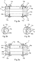
- the sealing insert 1 has an outer sealing section 3 for sealing against a recess and three inner sealing sections 5 (FIG. Fig. 5 ) of different diameter for sealing against pipes of different diameters. Furthermore, the sealing insert 1 comprises a first clamping device 7 for clamping the outer sealing section 3, wherein the inner sealing sections are decoupled from the outer sealing section 3 to avoid interference by the first clamping device 7.
- the first clamping device 7 has two clamping bodies 11a, 11b, which are movable relative to each other, for clamping the outer sealing section 3.
- the clamping bodies 11a, 11b of the first clamping device 7 each have a pressing surface 13a, b ( Fig. 2a ), wherein the pressing surfaces are movable relative to each other and between the pressing surfaces a shape-variable sealing body 15 is arranged made of an elastomeric material, which carries the outer sealing portion 3.
- the clamping bodies 11a, 11b each have four through holes. Through the through holes extend screws 12a-12d, wherein the tension of the clamping body 11a, 11b via corresponding nuts 14a-14d.
- the three inner sealing sections can each be braced in a fluid-tight manner with a conduit by means of a second tensioning device 9.
- the three inner sealing portions have annular cross-sections of different diameters and are coaxial arranged to each other.
- the sealing body 15 has in the regions of the inner sealing portions in each case two circumferential elevations 25a, 25b.
- the circumferential elevations 25a, 25b serve to align the second tensioning device 9.
- the three inner sealing sections 5 are arranged axially offset from one another.
- the three inner sealing portions 5 are connected to each other via web portions 27a, 27b.
- a third web 27c serves as a blind cover.
- the web portions 27a, 27b, c are pierceable by means of a tool, such as a screwdriver, and then can be torn by tensile force application.
- a handle 28 is formed, which is manually accessible for removing the blind cover ..
- the web portions 27a-c are separated by means of a respective predetermined breaking point 30a, b, c.
- the first clamping device 7 has two clamping bodies 11a, 11b which are movable relative to each other for clamping the outer sealing section 3 by means of the pressing surfaces 13a, b.
- the sealing body 15a, 15b is formed in several parts.
- the sealing body parts 15a, 15b carry the outer sealing section 3.
- Between the sealing body parts 15a, 15b is a clamping region of a further sealing body part (see, for example, reference numeral 15c in FIG 4 and FIG. 5 , and 115c in Fig. 8 ), wherein the further sealing body part carries the inner sealing portions.
- the clamping bodies 11a, 11b of the first clamping device 7 each have a support surface which supports the sealing body 15a, 15b in the radial direction inwards.
- the support surfaces comprise parallel to the outer sealing portion 3 extending support portions 29 a, 29 b.
- the clamping bodies 11a, 11b each have four through holes. Through the through holes extend screws 12a, 12b, wherein the clamping of the clamping body 11a, 11b via corresponding nuts 14a, 14b takes place.
- the first clamping device 7 also has two relatively movable clamping bodies 11a, 11b for clamping the outer sealing section 3 by means of the pressing surface 13a, b.
- the sealing body 15 carries the outer sealing portion 3.
- a Verspann Scheme another sealing body part see, for example, reference numeral 15c in 4 and FIG. 5 , and 115c in Fig. 8 ), wherein the further sealing body part carries the inner sealing portions.
- the clamping bodies 11a, 11b of the first clamping device 7 each have a support surface which supports the sealing body 15 in the radial direction inwards.
- the support surfaces include parallel to the outer sealing portion 3 extending support portions 29 a, 29 b and inclined to the outer sealing portion extending support portions 31a, 31b.
- the clamping bodies 11a, 11b each have four through holes. Through the through holes extend screws 12a, 12b, wherein the clamping of the clamping body 11a, 11b via corresponding nuts 14a, 14b takes place.
- Fig. 4 shows a first embodiment of a previously mentioned further sealing body part 15c.
- the clamping region 16 of the sealing body part 15c is connected to the inner sealing sections 5 via a flexible and variable-length compensator section 33.
- the clamping region 16 is between further sealing body parts (see, for example reference reference 15a, b in FIG Fig. 2a and 2b ) or above or below a sealing body (see, for example, reference numeral 15 in FIG Fig. 3a and 3b ) can be clamped.
- the Kompensatorabêt 33 is rotationally symmetrical and includes a double-folded membrane.
- the six inner sealing portions 5 have annular cross-sections of different diameters and are arranged coaxially with each other.
- the sealing body part 15c has two circumferential elevations 25a, 25b in the area of the outermost inner sealing section 5.
- the circumferential elevations 25a, 25b serve to align a tensioning device.
- the six inner sealing portions 5 are arranged side by side in the radial direction and connected to each other with web portions 27a to 27f.
- the web portions 27a to 27f are pierceable by means of a tool, such as a screwdriver, and then can be torn by tensile force application.
- Fig. 5 shows a further embodiment of the above-mentioned further sealing body part 15c.
- the clamping region 16 of the further sealing body part 15c is connected to the inner sealing sections 5 via a flexible and variable-length compensator section 33.
- the clamping region 16 is between other sealing body parts (see Fig. 2a and 2b ) or above or below a sealing body (see Fig. 3a and 3b ) can be clamped.
- the Kompensatorabêt 33 is rotationally symmetrical and includes a double-folded membrane.
- the three inner sealing portions 5 have annular cross-sections of different diameters and are arranged coaxially with each other.
- the sealing body part 15c has in the regions of the inner sealing portions 5 each two circumferential elevations 25a, 25b.
- the circumferential elevations 25a, 25b serve to align a tensioning device.
- the three inner sealing portions 5 are arranged axially offset from one another and connected to each other with web portions 27a, 27b.
- a third web portion 27c forms a blind cover.
- the web portions 27a, 27b, 27c are by means of a tool, such as a screwdriver, at respective predetermined breaking points 30a, b, c pierceable and then tear-tensile by Ceikraftaufbring.
- a handle 28 is formed, which is manually accessible by the fitter of the sealing insert 1 for removing the blind cover.
- the sealing insert 1 has an outer sealing portion 3 for sealing against a recess and two inner sealing portions 5 for sealing against pipes of different diameters.
- the sealing insert 1 further comprises a first clamping device 7 for clamping the outer sealing section 3, wherein the inner sealing sections 5 are decoupled from the outer sealing section 3 in order to avoid interference by the first clamping device 7.
- the first clamping device 7 has two clamping bodies 11a, 11b, which are movable relative to each other, for clamping the outer sealing section 3.
- Both clamping bodies 11a, 11b of the first clamping device 7 have a support surface, which supports the sealing body 15 in the radial direction inwards.
- the support surfaces of the two clamping bodies 11a, 11b each include a parallel to the outer sealing portion 3 extending support portion 29a, 29b
- the outer sealing section 3 is connected to the inner sealing sections 5 via a flexible and variable-length compensator section 33.
- the Kompensatorabites 33 is rotationally symmetrical and includes a double-folded membrane.
- the clamping bodies 11a, 11b of the first clamping device 7 each have a pressing surface 13a, 13b.
- the pressing surfaces 13a, 13b are movable relative to each other, wherein between the pressing surfaces 13a, 13b, a shape-changing sealing body 15 is arranged, which carries the outer sealing portion 3.
- the shape-changing sealing body 15 is formed of an elastomeric material.
- the movable clamping bodies 11a, 11b of the first clamping device 7 are formed of a dimensionally stable plastic.
- the clamping bodies 11a, 11b of the first clamping device each have a stop surface 17a, 17b, wherein the stop surfaces 17a, 17b are movable relative to each other.
- the abutment surfaces 17 a, 17 b strike in a stop position on the sealing body 15.
- abutment surfaces 17a, 17b and the pressing surfaces 13a, 13b are formed as surface portions of each integrally formed clamping body 11a, 11b of the first clamping device 7, performs a relative movement of the pressing surfaces 13a, 13b simultaneously to a relative movement of the stop surfaces 17a, 17b.
- a further stop can also be realized by the six movable abutment bodies 19 to 19f.
- the abutment bodies 19a to 19f in each case abut against an abutment surface 21a to 21f in a stop position.
- the stop bodies 19a to 19f are designed as screws and extend through a through hole of the lower clamping body 11b and engage in a threaded hole 23a to 23f in the upper clamping body 11a, respectively.
- the threaded bores 23a to 23f have a blind hole, wherein the bottom of the blind hole is formed as a stop surface 21a to 21f for the respective stop body 19a to 19f.
- the pressing surfaces 13a, 13b of the clamping bodies 11a, 11b of the first clamping device 7 are operatively connected to the stop bodies 19a to 19f, so that a movement, namely a rotation of the stop bodies 19a to 19f a relative movement of the pressing surfaces 13a, 13b of the clamping body 11a, 11b of the first Clamping 7 caused.
- a rotational movement of the abutment bodies 19a to 19f consequently leads either to an approximation of the clamping bodies 11a, 11b of the first clamping device 7 or to an increase in the distance between the clamping bodies 11a, 11b of the first clamping device 7.
- the sealing insert 1 has two inner sealing sections 5, which are arranged axially offset from one another.
- the sealing portions 5 are connected to each other via a web portion 27a.
- a second web portion 27b forms a blind cover.
- the web portions 27a, b are pierceable by means of a tool, such as a screwdriver, at a respective predetermined breaking point 30a, b and then by tensile force application, tear-open.
- a handle 28 is formed and serves to remove the blind cover.
- the sealing body 15a, 15b, 15c is formed in three parts, wherein the two sealing body parts 15a, 15b form the outer sealing portion 3 and the third sealing body part 15c has the inner sealing portions 5.
- the third sealing body part 15c is provided with a flange portion 16 between the first and second sealing body parts 15a, 15b clamped and clamped by means of the clamping body 11a, 11b between the sealing body parts 15a, 15b.
- Both clamping bodies 11a, 11b of the first clamping device 7 each have a support surface, which supports the first sealing body part 15a and the second sealing body part 15b in the radial direction inwards.
- the support surfaces of the two clamping bodies 11a, 11b each include a support portion 29a, 29b extending parallel to the outer sealing portion 3 and a support portion 31a, 31b inclined to the outer sealing portion 3.
- FIG. 8 the application of the inventive concept to multiple sealing inserts.
- a multiple sealing insert 100 stands as a first clamping device, for example, a clamping device 7 according to the FIGS. 2a, 3a, 7a to disposal.
- each of the further sealing body parts 115a-c is preferably analogous to the exemplary embodiment according to FIG. 5 educated.
- one or more or all or all of the sealing body parts 115a-c are, for example, according to the embodiment according to FIG. 4 trained (not shown).
- the sealing body parts 115a-c have, in the region of their inner sealing sections 105, respectively two circumferential elevations 125a, b, which serve to align any externally mountable clamping devices.
- the sealing body parts 115a-c each have a plurality of sealing portions 105a-c, which are connected to each other via web portions 127a, b, c.
- the web section 127c arranged on the smallest, third sealing section 105c serves as blind cover.
- the web portions 127a-c are pierceable by means of a tool, such as a screwdriver, preferably at a respective predetermined breaking point 130a-c and then tearing by tensile force application.
- a handle 128 is formed, which is manually accessible for removing the blind cover.
Landscapes
- Engineering & Computer Science (AREA)
- General Engineering & Computer Science (AREA)
- Mechanical Engineering (AREA)
- Architecture (AREA)
- Civil Engineering (AREA)
- Structural Engineering (AREA)
- Gasket Seals (AREA)
Applications Claiming Priority (1)
| Application Number | Priority Date | Filing Date | Title |
|---|---|---|---|
| DE202016101429.8U DE202016101429U1 (de) | 2016-03-15 | 2016-03-15 | Dichtungseinsatz zum Abdichten einer Leitung gegenüber einer Ausnehmung |
Publications (2)
| Publication Number | Publication Date |
|---|---|
| EP3220030A1 true EP3220030A1 (fr) | 2017-09-20 |
| EP3220030B1 EP3220030B1 (fr) | 2020-08-12 |
Family
ID=58227917
Family Applications (1)
| Application Number | Title | Priority Date | Filing Date |
|---|---|---|---|
| EP17158445.1A Active EP3220030B1 (fr) | 2016-03-15 | 2017-02-28 | Élément d'étanchéité d'une conduite par rapport à une ouverture |
Country Status (2)
| Country | Link |
|---|---|
| EP (1) | EP3220030B1 (fr) |
| DE (1) | DE202016101429U1 (fr) |
Families Citing this family (1)
| Publication number | Priority date | Publication date | Assignee | Title |
|---|---|---|---|---|
| DE102022118323B3 (de) * | 2022-07-21 | 2023-11-23 | WAGRO Systemdichtungen Gesellschaft mit beschränkter Haftung | Abdichtungsmatte, abgedichtete Rohrdurchführung und Verfahren zurAbdichtung einer Durchführung |
Citations (5)
| Publication number | Priority date | Publication date | Assignee | Title |
|---|---|---|---|---|
| DE29517409U1 (de) * | 1995-11-03 | 1997-03-13 | DOYMA GmbH & Co., 28876 Oyten | Kabeldurchführung mit Schutzrohr |
| US5988698A (en) * | 1997-07-08 | 1999-11-23 | Sergio M. Bravo | Flexible penetration fitting |
| EP2385286A1 (fr) * | 2010-05-05 | 2011-11-09 | Hauff-Technik GmbH & Co. KG | Passage de ligne avec empilement |
| EP2447583A1 (fr) * | 2010-10-28 | 2012-05-02 | Doyma GmbH & Co | Dispositif d'étanchéité |
| EP2589845A1 (fr) * | 2011-11-03 | 2013-05-08 | Hauff-Technik GmbH & Co. KG | Corps élastomère doté d'une suite de couches |
Family Cites Families (4)
| Publication number | Priority date | Publication date | Assignee | Title |
|---|---|---|---|---|
| DE7024205U (de) * | 1970-06-27 | 1970-10-22 | Brueckel R Ohg | Dachdurchführung für Dachständer, Antennenmaste, Gußstahldrähte oder Ankerseile |
| PL1669658T3 (pl) * | 2004-12-13 | 2008-09-30 | Nal Products Aps | Tuleja łącząca służąca do odgałęzienia rurowego |
| DE102006015847B4 (de) * | 2006-04-03 | 2008-10-23 | Hauff-Technik Gmbh & Co. Kg | Dichtpackung zum Einsetzen in eine Wandöffnung |
| DE202007017898U1 (de) * | 2007-12-21 | 2009-04-23 | Doyma Gmbh & Co. | Dichtungseinsatz mit radialen Lamellen |
-
2016
- 2016-03-15 DE DE202016101429.8U patent/DE202016101429U1/de active Active
-
2017
- 2017-02-28 EP EP17158445.1A patent/EP3220030B1/fr active Active
Patent Citations (5)
| Publication number | Priority date | Publication date | Assignee | Title |
|---|---|---|---|---|
| DE29517409U1 (de) * | 1995-11-03 | 1997-03-13 | DOYMA GmbH & Co., 28876 Oyten | Kabeldurchführung mit Schutzrohr |
| US5988698A (en) * | 1997-07-08 | 1999-11-23 | Sergio M. Bravo | Flexible penetration fitting |
| EP2385286A1 (fr) * | 2010-05-05 | 2011-11-09 | Hauff-Technik GmbH & Co. KG | Passage de ligne avec empilement |
| EP2447583A1 (fr) * | 2010-10-28 | 2012-05-02 | Doyma GmbH & Co | Dispositif d'étanchéité |
| EP2589845A1 (fr) * | 2011-11-03 | 2013-05-08 | Hauff-Technik GmbH & Co. KG | Corps élastomère doté d'une suite de couches |
Also Published As
| Publication number | Publication date |
|---|---|
| DE202016101429U1 (de) | 2017-06-19 |
| EP3220030B1 (fr) | 2020-08-12 |
Similar Documents
| Publication | Publication Date | Title |
|---|---|---|
| DE3531540C2 (de) | Eine die Trennung verhindernde Rohrverbindung | |
| EP2699388B1 (fr) | Outil de serrage pour un élément à visser associé à une conduite ainsi que pièce d'accouplement et élément à visser | |
| DE69901568T2 (de) | Vorrichtung zur abdichtung eine leckage in einer rohrleitung | |
| DE102016112782B4 (de) | Einsatz zur Verbindung eines elektrischen Anschlusses mit einer Wand | |
| DE102010052782A1 (de) | Fahrzeuginsassenrückhaltesystem für ein Fahrzeug und Dichtungselement | |
| DE10256855A1 (de) | Verfahren zur Montage eines zweireihigen Kegelrollenlagers | |
| EP2369211A2 (fr) | Dispositif pour le passage étanche de pièces longilignes | |
| DE2647043C2 (de) | Zugentlastungsvorrichtung für eine Kabeleinführung in ein Gehäuse eines elektrischen Gerätes | |
| WO2018178946A1 (fr) | Raccord de tuyaux | |
| EP3220031B1 (fr) | Élément d'étanchéité d'une conduite par rapport à un évidement | |
| EP3220030B1 (fr) | Élément d'étanchéité d'une conduite par rapport à une ouverture | |
| EP3715690A1 (fr) | Adaptateur pour raccords vissés de tuyaux flexibles | |
| DE29604873U1 (de) | Anschluß für Hochdruck-Metallrohre | |
| EP1484544B1 (fr) | Traversée de conduite pour l'installation d'un tube sanitaire à travers un mur | |
| DE10215608A1 (de) | Rohrverbinder | |
| EP3180231B1 (fr) | Barre d'accouplement ou de direction pour véhicule | |
| DE102006035404A1 (de) | Schnellspannmutter | |
| DE19912068B4 (de) | Wellen- oder Stellmutter und Verfahren zu ihrer Herstellung | |
| DE102015212532A1 (de) | Montagewerkzeug, Montageverfahren sowie Verwendung eines flexiblen Bandes | |
| EP1245888B1 (fr) | Adaptateur de position pour des connections de tuyaux et câbles | |
| CH669442A5 (en) | Compression connector for pipes - has two=part insert to clamp around male connector and with seal inside female sleeve | |
| DE102016103877B4 (de) | Motorlagerschild | |
| EP3738182A1 (fr) | Passe-câble à vis | |
| DE102005042428A1 (de) | Schelle zum Fixieren eines Rohres oder eines Kabels | |
| DE102018216086A1 (de) | Profilrohrsystem |
Legal Events
| Date | Code | Title | Description |
|---|---|---|---|
| PUAI | Public reference made under article 153(3) epc to a published international application that has entered the european phase |
Free format text: ORIGINAL CODE: 0009012 |
|
| STAA | Information on the status of an ep patent application or granted ep patent |
Free format text: STATUS: THE APPLICATION HAS BEEN PUBLISHED |
|
| AK | Designated contracting states |
Kind code of ref document: A1 Designated state(s): AL AT BE BG CH CY CZ DE DK EE ES FI FR GB GR HR HU IE IS IT LI LT LU LV MC MK MT NL NO PL PT RO RS SE SI SK SM TR |
|
| AX | Request for extension of the european patent |
Extension state: BA ME |
|
| STAA | Information on the status of an ep patent application or granted ep patent |
Free format text: STATUS: REQUEST FOR EXAMINATION WAS MADE |
|
| 17P | Request for examination filed |
Effective date: 20180320 |
|
| RBV | Designated contracting states (corrected) |
Designated state(s): AL AT BE BG CH CY CZ DE DK EE ES FI FR GB GR HR HU IE IS IT LI LT LU LV MC MK MT NL NO PL PT RO RS SE SI SK SM TR |
|
| STAA | Information on the status of an ep patent application or granted ep patent |
Free format text: STATUS: EXAMINATION IS IN PROGRESS |
|
| 17Q | First examination report despatched |
Effective date: 20180830 |
|
| GRAP | Despatch of communication of intention to grant a patent |
Free format text: ORIGINAL CODE: EPIDOSNIGR1 |
|
| STAA | Information on the status of an ep patent application or granted ep patent |
Free format text: STATUS: GRANT OF PATENT IS INTENDED |
|
| RIC1 | Information provided on ipc code assigned before grant |
Ipc: H02G 3/22 20060101ALI20191115BHEP Ipc: F16L 5/02 20060101AFI20191115BHEP Ipc: F16L 5/08 20060101ALI20191115BHEP |
|
| INTG | Intention to grant announced |
Effective date: 20191206 |
|
| GRAS | Grant fee paid |
Free format text: ORIGINAL CODE: EPIDOSNIGR3 |
|
| RIN1 | Information on inventor provided before grant (corrected) |
Inventor name: CHIKATIMALLA, RAJESH |
|
| GRAA | (expected) grant |
Free format text: ORIGINAL CODE: 0009210 |
|
| STAA | Information on the status of an ep patent application or granted ep patent |
Free format text: STATUS: THE PATENT HAS BEEN GRANTED |
|
| AK | Designated contracting states |
Kind code of ref document: B1 Designated state(s): AL AT BE BG CH CY CZ DE DK EE ES FI FR GB GR HR HU IE IS IT LI LT LU LV MC MK MT NL NO PL PT RO RS SE SI SK SM TR |
|
| REG | Reference to a national code |
Ref country code: CH Ref legal event code: NV Representative=s name: E. BLUM AND CO. AG PATENT- UND MARKENANWAELTE , CH Ref country code: CH Ref legal event code: EP |
|
| REG | Reference to a national code |
Ref country code: IE Ref legal event code: FG4D Free format text: LANGUAGE OF EP DOCUMENT: GERMAN |
|
| REG | Reference to a national code |
Ref country code: DE Ref legal event code: R096 Ref document number: 502017006674 Country of ref document: DE |
|
| REG | Reference to a national code |
Ref country code: AT Ref legal event code: REF Ref document number: 1301874 Country of ref document: AT Kind code of ref document: T Effective date: 20200915 |
|
| REG | Reference to a national code |
Ref country code: LT Ref legal event code: MG4D |
|
| REG | Reference to a national code |
Ref country code: NL Ref legal event code: MP Effective date: 20200812 |
|
| PG25 | Lapsed in a contracting state [announced via postgrant information from national office to epo] |
Ref country code: BG Free format text: LAPSE BECAUSE OF FAILURE TO SUBMIT A TRANSLATION OF THE DESCRIPTION OR TO PAY THE FEE WITHIN THE PRESCRIBED TIME-LIMIT Effective date: 20201112 Ref country code: SE Free format text: LAPSE BECAUSE OF FAILURE TO SUBMIT A TRANSLATION OF THE DESCRIPTION OR TO PAY THE FEE WITHIN THE PRESCRIBED TIME-LIMIT Effective date: 20200812 Ref country code: FI Free format text: LAPSE BECAUSE OF FAILURE TO SUBMIT A TRANSLATION OF THE DESCRIPTION OR TO PAY THE FEE WITHIN THE PRESCRIBED TIME-LIMIT Effective date: 20200812 Ref country code: NO Free format text: LAPSE BECAUSE OF FAILURE TO SUBMIT A TRANSLATION OF THE DESCRIPTION OR TO PAY THE FEE WITHIN THE PRESCRIBED TIME-LIMIT Effective date: 20201112 Ref country code: GR Free format text: LAPSE BECAUSE OF FAILURE TO SUBMIT A TRANSLATION OF THE DESCRIPTION OR TO PAY THE FEE WITHIN THE PRESCRIBED TIME-LIMIT Effective date: 20201113 Ref country code: LT Free format text: LAPSE BECAUSE OF FAILURE TO SUBMIT A TRANSLATION OF THE DESCRIPTION OR TO PAY THE FEE WITHIN THE PRESCRIBED TIME-LIMIT Effective date: 20200812 Ref country code: HR Free format text: LAPSE BECAUSE OF FAILURE TO SUBMIT A TRANSLATION OF THE DESCRIPTION OR TO PAY THE FEE WITHIN THE PRESCRIBED TIME-LIMIT Effective date: 20200812 |
|
| PG25 | Lapsed in a contracting state [announced via postgrant information from national office to epo] |
Ref country code: IS Free format text: LAPSE BECAUSE OF FAILURE TO SUBMIT A TRANSLATION OF THE DESCRIPTION OR TO PAY THE FEE WITHIN THE PRESCRIBED TIME-LIMIT Effective date: 20201212 Ref country code: RS Free format text: LAPSE BECAUSE OF FAILURE TO SUBMIT A TRANSLATION OF THE DESCRIPTION OR TO PAY THE FEE WITHIN THE PRESCRIBED TIME-LIMIT Effective date: 20200812 Ref country code: NL Free format text: LAPSE BECAUSE OF FAILURE TO SUBMIT A TRANSLATION OF THE DESCRIPTION OR TO PAY THE FEE WITHIN THE PRESCRIBED TIME-LIMIT Effective date: 20200812 Ref country code: PL Free format text: LAPSE BECAUSE OF FAILURE TO SUBMIT A TRANSLATION OF THE DESCRIPTION OR TO PAY THE FEE WITHIN THE PRESCRIBED TIME-LIMIT Effective date: 20200812 Ref country code: LV Free format text: LAPSE BECAUSE OF FAILURE TO SUBMIT A TRANSLATION OF THE DESCRIPTION OR TO PAY THE FEE WITHIN THE PRESCRIBED TIME-LIMIT Effective date: 20200812 |
|
| PG25 | Lapsed in a contracting state [announced via postgrant information from national office to epo] |
Ref country code: RO Free format text: LAPSE BECAUSE OF FAILURE TO SUBMIT A TRANSLATION OF THE DESCRIPTION OR TO PAY THE FEE WITHIN THE PRESCRIBED TIME-LIMIT Effective date: 20200812 Ref country code: CZ Free format text: LAPSE BECAUSE OF FAILURE TO SUBMIT A TRANSLATION OF THE DESCRIPTION OR TO PAY THE FEE WITHIN THE PRESCRIBED TIME-LIMIT Effective date: 20200812 Ref country code: DK Free format text: LAPSE BECAUSE OF FAILURE TO SUBMIT A TRANSLATION OF THE DESCRIPTION OR TO PAY THE FEE WITHIN THE PRESCRIBED TIME-LIMIT Effective date: 20200812 Ref country code: SM Free format text: LAPSE BECAUSE OF FAILURE TO SUBMIT A TRANSLATION OF THE DESCRIPTION OR TO PAY THE FEE WITHIN THE PRESCRIBED TIME-LIMIT Effective date: 20200812 Ref country code: EE Free format text: LAPSE BECAUSE OF FAILURE TO SUBMIT A TRANSLATION OF THE DESCRIPTION OR TO PAY THE FEE WITHIN THE PRESCRIBED TIME-LIMIT Effective date: 20200812 |
|
| REG | Reference to a national code |
Ref country code: DE Ref legal event code: R097 Ref document number: 502017006674 Country of ref document: DE |
|
| PG25 | Lapsed in a contracting state [announced via postgrant information from national office to epo] |
Ref country code: AL Free format text: LAPSE BECAUSE OF FAILURE TO SUBMIT A TRANSLATION OF THE DESCRIPTION OR TO PAY THE FEE WITHIN THE PRESCRIBED TIME-LIMIT Effective date: 20200812 Ref country code: ES Free format text: LAPSE BECAUSE OF FAILURE TO SUBMIT A TRANSLATION OF THE DESCRIPTION OR TO PAY THE FEE WITHIN THE PRESCRIBED TIME-LIMIT Effective date: 20200812 |
|
| PLBE | No opposition filed within time limit |
Free format text: ORIGINAL CODE: 0009261 |
|
| STAA | Information on the status of an ep patent application or granted ep patent |
Free format text: STATUS: NO OPPOSITION FILED WITHIN TIME LIMIT |
|
| PG25 | Lapsed in a contracting state [announced via postgrant information from national office to epo] |
Ref country code: SK Free format text: LAPSE BECAUSE OF FAILURE TO SUBMIT A TRANSLATION OF THE DESCRIPTION OR TO PAY THE FEE WITHIN THE PRESCRIBED TIME-LIMIT Effective date: 20200812 |
|
| 26N | No opposition filed |
Effective date: 20210514 |
|
| PG25 | Lapsed in a contracting state [announced via postgrant information from national office to epo] |
Ref country code: IT Free format text: LAPSE BECAUSE OF FAILURE TO SUBMIT A TRANSLATION OF THE DESCRIPTION OR TO PAY THE FEE WITHIN THE PRESCRIBED TIME-LIMIT Effective date: 20200812 |
|
| PG25 | Lapsed in a contracting state [announced via postgrant information from national office to epo] |
Ref country code: SI Free format text: LAPSE BECAUSE OF FAILURE TO SUBMIT A TRANSLATION OF THE DESCRIPTION OR TO PAY THE FEE WITHIN THE PRESCRIBED TIME-LIMIT Effective date: 20200812 |
|
| PG25 | Lapsed in a contracting state [announced via postgrant information from national office to epo] |
Ref country code: MC Free format text: LAPSE BECAUSE OF FAILURE TO SUBMIT A TRANSLATION OF THE DESCRIPTION OR TO PAY THE FEE WITHIN THE PRESCRIBED TIME-LIMIT Effective date: 20200812 |
|
| GBPC | Gb: european patent ceased through non-payment of renewal fee |
Effective date: 20210228 |
|
| REG | Reference to a national code |
Ref country code: BE Ref legal event code: MM Effective date: 20210228 |
|
| PG25 | Lapsed in a contracting state [announced via postgrant information from national office to epo] |
Ref country code: LU Free format text: LAPSE BECAUSE OF NON-PAYMENT OF DUE FEES Effective date: 20210228 |
|
| PG25 | Lapsed in a contracting state [announced via postgrant information from national office to epo] |
Ref country code: GB Free format text: LAPSE BECAUSE OF NON-PAYMENT OF DUE FEES Effective date: 20210228 Ref country code: FR Free format text: LAPSE BECAUSE OF NON-PAYMENT OF DUE FEES Effective date: 20210228 Ref country code: IE Free format text: LAPSE BECAUSE OF NON-PAYMENT OF DUE FEES Effective date: 20210228 |
|
| PGFP | Annual fee paid to national office [announced via postgrant information from national office to epo] |
Ref country code: CH Payment date: 20220221 Year of fee payment: 6 Ref country code: AT Payment date: 20220215 Year of fee payment: 6 |
|
| PG25 | Lapsed in a contracting state [announced via postgrant information from national office to epo] |
Ref country code: BE Free format text: LAPSE BECAUSE OF NON-PAYMENT OF DUE FEES Effective date: 20210228 |
|
| PG25 | Lapsed in a contracting state [announced via postgrant information from national office to epo] |
Ref country code: PT Free format text: LAPSE BECAUSE OF FAILURE TO SUBMIT A TRANSLATION OF THE DESCRIPTION OR TO PAY THE FEE WITHIN THE PRESCRIBED TIME-LIMIT Effective date: 20201214 |
|
| PG25 | Lapsed in a contracting state [announced via postgrant information from national office to epo] |
Ref country code: HU Free format text: LAPSE BECAUSE OF FAILURE TO SUBMIT A TRANSLATION OF THE DESCRIPTION OR TO PAY THE FEE WITHIN THE PRESCRIBED TIME-LIMIT; INVALID AB INITIO Effective date: 20170228 |
|
| P01 | Opt-out of the competence of the unified patent court (upc) registered |
Effective date: 20230414 |
|
| PG25 | Lapsed in a contracting state [announced via postgrant information from national office to epo] |
Ref country code: CY Free format text: LAPSE BECAUSE OF FAILURE TO SUBMIT A TRANSLATION OF THE DESCRIPTION OR TO PAY THE FEE WITHIN THE PRESCRIBED TIME-LIMIT Effective date: 20200812 |
|
| REG | Reference to a national code |
Ref country code: CH Ref legal event code: PL |
|
| REG | Reference to a national code |
Ref country code: AT Ref legal event code: MM01 Ref document number: 1301874 Country of ref document: AT Kind code of ref document: T Effective date: 20230228 |
|
| PG25 | Lapsed in a contracting state [announced via postgrant information from national office to epo] |
Ref country code: LI Free format text: LAPSE BECAUSE OF NON-PAYMENT OF DUE FEES Effective date: 20230228 Ref country code: CH Free format text: LAPSE BECAUSE OF NON-PAYMENT OF DUE FEES Effective date: 20230228 Ref country code: AT Free format text: LAPSE BECAUSE OF NON-PAYMENT OF DUE FEES Effective date: 20230228 |
|
| PG25 | Lapsed in a contracting state [announced via postgrant information from national office to epo] |
Ref country code: MK Free format text: LAPSE BECAUSE OF FAILURE TO SUBMIT A TRANSLATION OF THE DESCRIPTION OR TO PAY THE FEE WITHIN THE PRESCRIBED TIME-LIMIT Effective date: 20200812 |
|
| PGFP | Annual fee paid to national office [announced via postgrant information from national office to epo] |
Ref country code: DE Payment date: 20240312 Year of fee payment: 8 |