EP3219558A1 - Wiper system and wiper system control method - Google Patents
Wiper system and wiper system control method Download PDFInfo
- Publication number
- EP3219558A1 EP3219558A1 EP15858286.6A EP15858286A EP3219558A1 EP 3219558 A1 EP3219558 A1 EP 3219558A1 EP 15858286 A EP15858286 A EP 15858286A EP 3219558 A1 EP3219558 A1 EP 3219558A1
- Authority
- EP
- European Patent Office
- Prior art keywords
- wiper
- blade
- wiper blade
- prescribed
- prescribed position
- Prior art date
- Legal status (The legal status is an assumption and is not a legal conclusion. Google has not performed a legal analysis and makes no representation as to the accuracy of the status listed.)
- Granted
Links
Images

Classifications
-
- B—PERFORMING OPERATIONS; TRANSPORTING
- B60—VEHICLES IN GENERAL
- B60S—SERVICING, CLEANING, REPAIRING, SUPPORTING, LIFTING, OR MANOEUVRING OF VEHICLES, NOT OTHERWISE PROVIDED FOR
- B60S1/00—Cleaning of vehicles
- B60S1/02—Cleaning windscreens, windows or optical devices
- B60S1/04—Wipers or the like, e.g. scrapers
- B60S1/06—Wipers or the like, e.g. scrapers characterised by the drive
- B60S1/08—Wipers or the like, e.g. scrapers characterised by the drive electrically driven
-
- B—PERFORMING OPERATIONS; TRANSPORTING
- B60—VEHICLES IN GENERAL
- B60S—SERVICING, CLEANING, REPAIRING, SUPPORTING, LIFTING, OR MANOEUVRING OF VEHICLES, NOT OTHERWISE PROVIDED FOR
- B60S1/00—Cleaning of vehicles
- B60S1/02—Cleaning windscreens, windows or optical devices
- B60S1/04—Wipers or the like, e.g. scrapers
- B60S1/06—Wipers or the like, e.g. scrapers characterised by the drive
- B60S1/08—Wipers or the like, e.g. scrapers characterised by the drive electrically driven
- B60S1/0803—Intermittent control circuits
- B60S1/0807—Intermittent control circuits using electronic control means, e.g. tubes, semiconductors
-
- B—PERFORMING OPERATIONS; TRANSPORTING
- B60—VEHICLES IN GENERAL
- B60S—SERVICING, CLEANING, REPAIRING, SUPPORTING, LIFTING, OR MANOEUVRING OF VEHICLES, NOT OTHERWISE PROVIDED FOR
- B60S1/00—Cleaning of vehicles
- B60S1/02—Cleaning windscreens, windows or optical devices
- B60S1/04—Wipers or the like, e.g. scrapers
- B60S1/0452—Position of the wipers relative to the vehicle
-
- B—PERFORMING OPERATIONS; TRANSPORTING
- B60—VEHICLES IN GENERAL
- B60S—SERVICING, CLEANING, REPAIRING, SUPPORTING, LIFTING, OR MANOEUVRING OF VEHICLES, NOT OTHERWISE PROVIDED FOR
- B60S1/00—Cleaning of vehicles
- B60S1/02—Cleaning windscreens, windows or optical devices
- B60S1/04—Wipers or the like, e.g. scrapers
- B60S1/0452—Position of the wipers relative to the vehicle
- B60S1/0458—Arrangement wherein the windscreen frame cooperates with the wipers
- B60S1/0461—Arrangement of the side pillars
-
- B—PERFORMING OPERATIONS; TRANSPORTING
- B60—VEHICLES IN GENERAL
- B60S—SERVICING, CLEANING, REPAIRING, SUPPORTING, LIFTING, OR MANOEUVRING OF VEHICLES, NOT OTHERWISE PROVIDED FOR
- B60S1/00—Cleaning of vehicles
- B60S1/02—Cleaning windscreens, windows or optical devices
- B60S1/04—Wipers or the like, e.g. scrapers
- B60S1/0452—Position of the wipers relative to the vehicle
- B60S1/0469—Devices for assisting the wiper positioning on the vehicle
Definitions
- Patent Document 1 JP 2008-18900 A
- Two wiper shafts (pivot shafts) 4a and 4b are arranged on a vehicle body.
- the arms 1a and 1b are attached at their bottom to the wiper shafts 4a and 4b, respectively.
- the wiper system of FIG. 1 has a so-called direct drive wiper configuration.
- Alphabetic symbols "a” and “b” accompanying the reference signs indicate that the members or portions are associated with the driver's seat side and the assistant driver's seat side, respectively.
- the system includes two electric motors 6b and 6b (hereinafter, abbreviated as motors 6a and 6b).
- the motors 6a and 6b each include a motor main body 7 and a reduction mechanism 8.
- the motors 6a and 6b are PWM duty-controlled by wiper control devices (control means) 10a and 10b to make forward and reverse rotations.
- the wiper control device 10a which performs driving control on the motor 6a is connected to an ECU 11, which is a vehicle-side controller, via an on-vehicle LAN 12.
- the ECU 11 inputs switch information, such as ON/OFF of a wiper switch and Lo, Hi, and INT (intermittent operation), engine start information, and the like into the wiper control device 10a via the LAN 12.
- the wiper control devices 10a and 10b are connected to each other by a communication line 13.
- the wiper system according to the present invention can learn the angles of the blades 2a and 2b (hereinafter, referred to as blade angles) after the arms 1a and 1b are attached to the wiper shafts 4a and 4b. That is, the wiper control devices 10a and 10b can learn the blade angles and correct position information (angle data) for control. Variations in angle in attaching the arms can thus be absorbed and calibrated to improve control accuracy. As a result, work accuracy is relaxed and work burden on the worker is reduced.
- the wiper system issues a command to perform the "learning mode" to the wiper control devices 10a and 10b after the arms 1a and 1b are attached to the wiper shafts 4a and 4b.
- the blades 2a and 2b are automatically activated to perform learning and correction of the blade position information.
- the wiper control devices 10a and 10b on the DR side and the AS side perform the learning processing while performing synchronization control with each other. As illustrated in FIG.
- Various sensors including optical and magnetic types, may be applied as long as the sensors can detect the proximity of the blade to the prescribed position.
- model data of the vehicle on which the wiper system is mounted is also referred to, to accommodate itself to the shape, curvature, and the like of the windshield which vary from one vehicle model to another.
Landscapes
- Engineering & Computer Science (AREA)
- Mechanical Engineering (AREA)
- Control Of Position Or Direction (AREA)
- Control Of Electric Motors In General (AREA)
- Feedback Control In General (AREA)
- Control Of Multiple Motors (AREA)
Abstract
Description
- The present invention relates to a technique for controlling a vehicle wiper system mounted on an automobile and the like, and more particularly to initial setting processing when attaching a wiper apparatus to a vehicle.
- Vehicles such as an automobile are equipped with wiper apparatuses for wiping off rain water adhering to a windshield (front windshield) and splashes from front vehicles for the purpose of ensuring the driver's field of view in cases of rainy weather. A wiper apparatus includes a wiper arm which is controlled to oscillate by a wiper driving device. A wiper blade which comes into contact with a windshield is attached to the end of the wiper arm. A pivot shaft which is driven to rotate by a wiper motor is arranged on the body side of the vehicle. The wiper arm is attached to the pivot shaft, and oscillates at a preset control angle according to rotation of the motor.
- In attaching a wiper arm to a pivot shaft, the wiper arm has conventionally been fixed to the pivot shaft with an arm position set so that the wiper arm operates at a predetermined control angle. Since the position of the wiper arm is designed on the basis of theoretical values calculated in advance, the position of the wiper blade varies vehicle by vehicle due to dimensional errors, rigidity, and the like of the wiper arm, the wiper blade, and the body. In particular, when an assembly of a wiper arm and a wiper blade (hereinafter, abbreviated as arm & blade) is mounted on the vehicle body, the wiper arm is attached by using a predetermined jig because the assembly is susceptible to deflection of the arm or the blade. For example, in a conventional wiper attaching operation, the arm is initially stopped at a lower retracted position. The wiper arm is then fastened with a nut and mounted on the pivot shaft by using a dedicated jig so that the end of the wiper blade falls within a prescribed range.
- Patent Document 1:
JP 2008-18900 A - However, the wiper arm has been rather difficult to accurately mount within the prescribed range even by using a jig because of the arm shape, sinking of the arm due to axial force (force acting in the axial direction), the shape of the windshield, vehicle rigidity, and variations in parts. Since the wiper arm and the like need to be attached swiftly, there has also been a problem that the difficult work needs to be performed in a short time, with high burden on the worker. In the case of a so-called direct drive wiper in which the wiper arm is directly attached to the output shaft of a motor unit without a link mechanism, the pivot shaft of the driver wiper is unfavorably easily caused to rotate when a nut is clamped because of its mechanical structure. As a result, the work of attaching the arm & blade within a predetermined angle range becomes even more difficult. There has also been a problem that once an arm is mounted outside a prescribed range, the arm is not able to be reused and needs to be disposed because the fitting to the pivot shaft leaves serrated marks.
- A wiper system according to the present invention is a wiper system including a wiper blade that is arranged on a wiping surface, a wiper arm to which the wiper blade is attached, a pivot shaft that is installed on a vehicle side and to which the wiper arm is fixed, an electric motor that drives the pivot shaft to rotate, and a control device that performs operation control on the electric motor on the basis of position information about the wiper blade. The control device has a learning mode that is executed after the wiper arm is attached to the pivot shaft and in which a position of the wiper blade is learned to correct the position information. The learning mode includes moving the wiper blade to a predetermined prescribed position, detecting that the wiper blade is located in the prescribed position, and correcting the position information to a value corresponding to the prescribed position.
- In the wiper system, the control device may include a learning operation start unit that moves the wiper blade to the prescribed position when in the learning mode, a blade position check unit that detects that the wiper blade is located in the prescribed position when in the learning mode, and a position information learning and correction unit that, if the wiper blade is detected to be located in the prescribed position, corrects the position information to the value corresponding to the prescribed position.
- Any one of (a) an A-pillar interference position, (b) an upper reversing position, (c) a blade interference upper limit position, (d) a lower reversing position, (e) an intermittent stop position, (f) a lower retracted position, and (g) a lower vehicle body contact position may be employed as the prescribed position.
- That the wiper blade is located in the prescribed position may be detected by using a sensor or a video image. In such a case, a proximity sensor and the like may be arranged on the wiping surface, a vehicle body, a jig, or the wiper blade or the wiper arm itself. That the wiper blade is present in the prescribed position may be detected. The wiping surface may be captured by a camera. A camera may be installed on the wiper blade or the wiper arm, and the obtained image may be subjected to image processing to detect that the wiper blade is present in the prescribed position.
- A contact member may be arranged in the prescribed position, the wiper blade may be stopped at the prescribed position by the contact member, and that the wiper blade is located in the prescribed position may be detected from a stop of the wiper blade. In such a case, a jig may be arranged in the prescribed position and part or all of the arm or blade may be contacted with the jig to stop the blade at the prescribed position. The blade may be stopped, for example, by using part of the vehicle body, such as an A-pillar, or an anti-reversing member arranged on the vehicle body side as the contact member.
- A wiper system control method according to the present invention is a wiper system control method for controlling a wiper system including a wiper blade that is arranged on a wiping surface, a wiper arm to which the wiper blade is attached, a pivot shaft that is installed on a vehicle side and to which the wiper arm is fixed, and an electric motor that drives the pivot shaft to rotate. Operation control on the electric motor is performed on the basis of position information about the wiper blade. The wiper system control method includes, after the wiper arm is attached to the pivot shaft, executing a learning mode in which a position of the wiper blade is learned to correct the position information. The learning mode includes moving the wiper blade to a predetermined prescribed position, detecting that the wiper blade is located in the prescribed position, and correcting the position information to a value corresponding to the prescribed position.
- According to the present invention, the learning mode is executed to move the wiper blade to the prescribed position after the wiper arm is assembled to the pivot shaft. After the wiper blade is recognized to be present in the prescribed position, the position information for control is learned and corrected. The position information can thus be changed on the actually-installed windshield surface, and errors in the position information due to variations in the attached position of the wiper blade can be suppressed to be small. Since the position information is learned after the wiper arm is mounted, the work accuracy needed in attaching the blade is relaxed and the work burden on the worker is reduced.
- According to the wiper system and the wiper system control method of the present invention, the wiper system performs operation control on the electric motor, which drives and rotates the pivot shaft to which the wiper arm is fixed, based on the position information about the wiper blade, wherein the learning mode in which the position of the wiper blade is learned to correct the position information is executed after the wiper arm is attached to the pivot shaft. The position information about the wiper blade can thus be changed on the actually-installed wiping surface. This can reduce errors in the blade position information due to variations in the attached position of the wiper blade, and improve control accuracy and wiping performance.
- Since the position information about the wiper blade is learned after the wiper arm is mounted, the work accuracy in attaching the blade is relaxed. This facilitates the setting of the arm & blade, and reduces the work burden on the worker. Since the arm & blade are easily and accurately set, reassembling work for angle correction is not needed. This reduces disposal loss due to attachment failures, and cut manufacturing costs.
-
-
FIG. 1 is an explanatory diagram illustrating an overall configuration of a wiper system which is an embodiment of the present invention. -
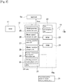
FIG. 2 is a block diagram illustrating a configuration of a control system of a wiper control device. -
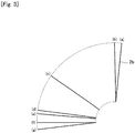
FIG. 3 is an explanatory diagram illustrating examples of a prescribed position of a blade serving as a reference for learning processing. -
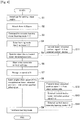
FIG. 4 is a flowchart illustrating an example of a procedure of the learning processing. - An embodiment of the present invention will be described in detail below with reference to the accompanying drawings. An object of the following embodiment is to facilitate work for attaching an arm & blade and improve accuracy of the attached position for reduced disposal loss.
FIG. 1 is an explanatory diagram illustrating an overall configuration of a wiper system which is an embodiment of the present invention. The wiper system ofFIG. 1 has an apparatus configuration of opposite wiping type. Awiper arm 1a on a driver's seat side (DR side) and awiper arm 1b on an assistant driver's seat side (AS side) (hereinafter, abbreviated asarms Wiper blades blades arms blades arms - Two wiper shafts (pivot shafts) 4a and 4b are arranged on a vehicle body. The
arms wiper shafts FIG. 1 has a so-called direct drive wiper configuration. Alphabetic symbols "a" and "b" accompanying the reference signs indicate that the members or portions are associated with the driver's seat side and the assistant driver's seat side, respectively. To oscillate thearms electric motors motors motors main body 7 and areduction mechanism 8. - The
motors wiper control device 10a which performs driving control on themotor 6a is connected to anECU 11, which is a vehicle-side controller, via an on-vehicle LAN 12. TheECU 11 inputs switch information, such as ON/OFF of a wiper switch and Lo, Hi, and INT (intermittent operation), engine start information, and the like into thewiper control device 10a via theLAN 12. Thewiper control devices communication line 13. - The wiper system of
FIG. 1 performs feedback control (PI control) on themotors blades blades wiper control devices wiper control devices blades blades wiper shafts wiper shafts wiper shafts motors blades blades motors - The
wiper control devices motors communication line 13. Thewiper control devices motors wiper control devices motors wiper control devices motors blades blades wiping range 5, and rain and snow adhering to thewindshield 3 are wiped off. - The wiper system according to the present invention can learn the angles of the
blades arms wiper shafts wiper control devices - To learn the blade angles, predetermined blade positions (for example, upper reversing positions) are initially set as prescribed positions in advance. After the arms are attached, the
blades blades - The
wiper control devices wiper control devices FIG. 2 is a block diagram illustrating a configuration of a control system of thewiper control device 10a. Since thewiper control devices FIG. 2 and the following description deal only with thewiper control device 10a. - The
wiper control device 10a includes aCPU 21 and a data transmission andreception unit 22. Thewiper control device 10a is connected to theECU 11 via theLAN 12. TheECU 11 inputs a setting state (operation mode settings such as ON/OFF, Lo, Hi, and INT) of the wiper switch and various types of vehicle information, such as an engine start signal, to thewiper control device 10a. Thewiper control device 10a further includes aROM 23 and aRAM 24. TheROM 23 stores various control programs including the correction and learning function, and various types of control information. TheRAM 24 stores control data such as the number of rotations of the motor and the current position of the blade. - The
CPU 21 is a central arithmetic processing unit. In the present system, theCPU 21 connected with theECU 11 serves as a master side, and the CPU of the not-illustratedwiper control device 10b as a slave side. TheCPU 21 of thewiper control unit 10a is connected to the CPU of thewiper control device 10b via the data transmission andreception units 22 and thecommunication line 13. The two CPUs exchange blade position information and operation instructions with each other through thecommunication line 13. The master-side CPU 21 controls an operation of themotor 6a on the basis of the position information about theblade 2b transmitted from thewiper control apparatus 10b and its own position information (about theblade 2a) according to the state of the wiper switch. The slave-side CPU controls an operation of themotor 6b on the basis of the position information about theblade 2a transmitted from thewiper control device 10a and its own position information (about theblade 2b) according to instructions from thewiper control device 10a. - The
CPU 21 includes a bladeposition detection unit 25 and a bladespeed detection unit 26. The bladeposition detection unit 25 detects the current position of theblade 2a from a sensor signal output from the magnetic sensor arranged on themotor 6a. The bladespeed detection unit 26 detects the current speed of theblade 2a from the sensor signal. TheCPU 21 also includes a learningoperation start unit 27, a bladeposition check unit 28, and a position information learning andcorrection unit 29. When the "learning mode" is selected, the learningoperation start unit 27 starts the learning mode and automatically moves theblade 2a to a predetermined prescribed position. When theblade 2a is moved to the prescribed position according to the start of the learning mode, the bladeposition check unit 28 detects that theblade 2a has reached the prescribed position and is located there. That theblade 2a is moved to the prescribed position is detected by using an external prescribed position detecting means 31 or from a change in motor speed, etc. When theblade 2a is confirmed to be in the prescribed position by the bladeposition check unit 28, the position information learning andcorrection unit 29 corrects the position information about theblade 2a to correspond to the prescribed position. - The
CPU 21 further includes a drivingcontrol instruction unit 30. During the learning mode, the drivingcontrol instruction unit 30 actuates theblade 2a toward the prescribed position. During a normal operation, the drivingcontrol instruction unit 30 operates theblade 2a between the upper and lower reversing positions as appropriate. During the normal operation, the drivingcontrol instruction unit 30 instructs themotor 6a about the direction of rotation, duty, and the like on the basis of the blade position information, whereby reciprocations of theblade 2a are controlled. - The wiper system according to the present invention issues a command to perform the "learning mode" to the
wiper control devices arms wiper shafts blades wiper control devices FIG. 3 , possible prescribed positions of a blade to serve as a reference for the learning processing, including the foregoing upper reversing position, may include: (a) an A-pillar interference position, (b) the upper reversing position, (c) an interference upper limit position between theblades blades arms FIG. 3 illustrates various prescribed positions about theblade 2b; similarly, prescribed positions are set also on theblade 2a side. - Examples of a method for detecting that the
blades - Methods using a sensor as the prescribed position detection means 31 may include:
- (1) Install the sensor on the
windshield 3 and detect the blade position (presence in the prescribed position); - (2) Install the sensor on the body side;
- (3) Install the sensor on a jig; and
- (4) Install the sensor on the arm or blade.
- (1) Install the sensor on the
- Various sensors, including optical and magnetic types, may be applied as long as the sensors can detect the proximity of the blade to the prescribed position.
- Methods using a video image include the following. Here, a camera is used as the prescribed position detection means 31:
- (5) Capture the windshield surface by the camera, and detect the blade position by image processing; and
- (6) Install the camera on the arm or blade, and detect the blade position from the image.
- In (1) to (6), a stopper member for suppressing operation is installed on the body side to prevent the
blades - Means using a physical contact member include the following. Here, the external prescribed position detection means 31 is not used. Instead, the blades are brought into contact with the contact member so that the blade speed becomes zero, from which the
blades - (7) Install a jig in the prescribed position, and bring part or all of the arms or blades into contact with the jig. Stop the
blades - (8) Use the body (for example, an A-pillar: front window pillar) as the contact member. Bring part or all of the arms or blades into contact with the body to stop the
blades - (9) Use a body-side anti-reversing member (for example, a stopper arranged in the extended retracted position, on the motor, on a link mechanism, etc.) as the contact member. Bring part or all of the arms or blades into contact with the anti-reversing member to stop the
blades - As described above, according to this wiper system, a plurality of prescribed positions and a plurality of prescribed position detection means are applicable. The "learning mode" is then executed by a method appropriately combining such positions and means (in the foregoing cases, combinations of (a) to (g) and (1) to (9) provide 7 × 9 = 63 possible methods). As an example, a case of combining (f) and (7) in which the learning mode is executed with a jig installed in the lower retracted position will be described.
FIG. 4 is a flowchart illustrating a procedure when thearms wiper shafts - As illustrated in
FIG. 4 , before execution of the learning mode, jigs for setting wiper angles are installed in the lower retracted positions (step S1). Thearms wiper shafts wiper control devices wiper control devices wiper control devices - Entering the learning mode, the
wiper control devices blades blades blades blades blades speed detection units 26 detect a speed of 0 (step S7). The position information learning andcorrection units 29 detect that theblades - Recognizing the presence of the
blades correction units 29 make the bladeposition check units 28 to correct the blade position information. More specifically, the angles of theblades position check unit 28, thewiper control devices - In the procedure of
FIG. 4 , the movement to the prescribed positions at a start of the learning mode is automatically performed by the learning and correction program stored in theROM 23. However, a command to move the blades may be given from an external control device (broken-line path: step S11). In such a case, thewiper control devices blades - If the prescribed positions are specified from outside, the blade position information is corrected before a signal (lower retracted position information = 1) indicating that the
blades wiper control devices wiper control devices - As described above, in the wiper system according to the present invention, the
arms blades blades blades - Since the blade angles are learned after the arms are mounted, high accuracy is not needed of the initially attached positions of the blades. This facilitates the attachment of the arms & blades, and reduces work burden on the worker. Since the learning processing is automatically executed according to the mode setting, assembly workability also improves. Since the arms & blades can be easily and accurately attached, reassembling work for angle correction is not needed. This reduces disposal loss due to attachment failures, and cuts manufacturing costs. In addition, since the blade position information can be set after the mounting on the vehicle, the wiper arms and blades can be shared by a plurality of vehicle models.
- The present invention is not limited to the foregoing embodiment, and it will be understood that various modifications may be made without departing from the gist thereof.
- In the foregoing embodiment, the seven locations (a) to (g) are described as examples of prescribed positions, while other locations may be used as prescribed positions. For example, a hood (engine hood) interference angle (angle at which the hood and a wiper blade interfere with each other when the hood is opened with the wiper blade erected) may be used. A "learning mode check position" may be specially set for the purpose of the learning processing. In other words, prescribe positions can be arbitrarily set as long as the prescribed positions can be recognized as such. While a combination of a sensor magnet and a magnetic sensor such as a Hall IC is described to be used as means for detecting the rotation speed of the
wiper shafts motors - In the foregoing embodiment, the present invention is described to be applied to a wiper apparatus of opposite wiping type in which two electric motors are laterally symmetrically arranged with the respect to the windshield, and the wiper arms on the driver's seat side and the assistant driver's seat side are operated to wipe in opposite directions. However, the present invention may be applied to a wiper apparatus of tandem type in which the wiper arms on the driver's seat side and the assistant driver's seat side are operated to wipe in substantially the same direction. While the wipers are described to have a direct drive wiper configuration, the present invention may be applied to wipers using a link mechanism.
-
- 1a, 1b:
- Wiper arm
- 2a, 2b:
- Wiper blade
- 3:
- Windshield
- 4a, 4b:
- Wiper shaft
- 5:
- Wiping range
- 6a, 6b:
- Motor
- 7:
- Motor main body
- 8:
- Reduction mechanism
- 10a, 10b:
- Wiper control device
- 11:
- ECU
- 12:
- On-vehicle LAN
- 13:
- Communication line
- 21:
- CPU
- 22:
- Data transmission and reception unit
- 23:
- ROM
- 24:
- RAM
- 25:
- Blade position detection unit
- 26:
- Blade speed detection unit
- 27:
- Learning operation start unit
- 28:
- Blade position check unit
- 29:
- Position information learning and correction unit
- 30:
- Driving control instruction unit
- 31:
- Prescribed position detection means
Claims (7)
- A wiper system comprising:a wiper blade that is arranged on a wiping surface;a wiper arm to which the wiper blade is attached;a pivot shaft that is installed on a vehicle side and to which the wiper arm is fixed;an electric motor that drives the pivot shaft to rotate; anda control device that performs operation control on the electric motor based on position information about the wiper blade,the control device having a learning mode that is executed after the wiper arm is attached to the pivot shaft and in which a position of the wiper blade is learned to correct the position information,the learning mode including moving the wiper blade to a predetermined prescribed position, detecting that the wiper blade is located in the prescribed position, and correcting the position information to a value corresponding to the prescribed position.
- The wiper system according to claim 1, wherein the control device includes:a learning operation start unit that moves the wiper blade to the prescribed position during the learning mode;a blade position check unit that detects that the wiper blade is located in the prescribed position during the learning mode; anda position information learning and correction unit that, if the wiper blade is detected to be located in the prescribed position, corrects the position information to the value corresponding to the prescribed position.
- The wiper system according to claim 1 or 2, wherein the prescribed position is any one of (a) an A-pillar interference position, (b) an upper reversing position, (c) a blade interference upper limit position, (d) a lower reversing position, (e) an intermittent stop position, (f) a lower retracted position, and (g) a lower vehicle body contact position.
- The wiper system according to any one of claims 1 to 3, wherein that the wiper blade is located in the prescribed position is detected by using a sensor.
- The wiper system according to any one of claims 1 to 3, wherein that the wiper blade is located in the prescribed position is detected by using a video image.
- The wiper system according to any one of claims 1 to 3, wherein a contact member is arranged in the prescribed position, the wiper blade is stopped at the prescribed position by the contact member, and that the wiper blade is located in the prescribed position is detected from a stop of the wiper blade.
- A wiper system control method for controlling a wiper system including
a wiper blade that is arranged on a wiping surface,
a wiper arm to which the wiper blade is attached,
a pivot shaft that is installed on a vehicle side and to which the wiper arm is fixed, and
an electric motor that drives the pivot shaft to rotate,
operation control on the electric motor being performed on the basis of position information about the wiper blade,
the wiper system control method comprising,
after the wiper arm is attached to the pivot shaft, executing a learning mode in which a position of the wiper blade is learned to correct the position information,
the learning mode including moving the wiper blade to a predetermined prescribed position, detecting that the wiper blade is located in the prescribed position, and correcting the position information to a value corresponding to the prescribed position.
Applications Claiming Priority (2)
| Application Number | Priority Date | Filing Date | Title |
|---|---|---|---|
| JP2014227692A JP6396178B2 (en) | 2014-11-10 | 2014-11-10 | Wiper system and wiper system control method |
| PCT/JP2015/081172 WO2016076195A1 (en) | 2014-11-10 | 2015-11-05 | Wiper system and wiper system control method |
Publications (3)
| Publication Number | Publication Date |
|---|---|
| EP3219558A1 true EP3219558A1 (en) | 2017-09-20 |
| EP3219558A4 EP3219558A4 (en) | 2018-07-25 |
| EP3219558B1 EP3219558B1 (en) | 2021-01-13 |
Family
ID=55954284
Family Applications (1)
| Application Number | Title | Priority Date | Filing Date |
|---|---|---|---|
| EP15858286.6A Active EP3219558B1 (en) | 2014-11-10 | 2015-11-05 | Wiper system and wiper system control method |
Country Status (6)
| Country | Link |
|---|---|
| US (1) | US10543811B2 (en) |
| EP (1) | EP3219558B1 (en) |
| JP (1) | JP6396178B2 (en) |
| CN (1) | CN107074201A (en) |
| MX (1) | MX392186B (en) |
| WO (1) | WO2016076195A1 (en) |
Families Citing this family (9)
| Publication number | Priority date | Publication date | Assignee | Title |
|---|---|---|---|---|
| KR101950781B1 (en) * | 2017-05-26 | 2019-02-22 | 대한민국 | Test Device For Wiper Mounting And Wiper Test Drive Method |
| CN108501874B (en) * | 2018-03-21 | 2020-05-19 | 北京汽车股份有限公司 | Vehicle and self-learning control method and device for windscreen wiper thereof |
| JP7115954B2 (en) * | 2018-10-12 | 2022-08-09 | 株式会社ミツバ | Wiper device |
| US11628806B2 (en) * | 2019-11-21 | 2023-04-18 | Honda Motor Co., Ltd. | Systems and methods for calibrating a windshield wiper system |
| CN113119910A (en) * | 2020-01-10 | 2021-07-16 | 博世汽车部件(长沙)有限公司 | Wiper device and control method for wiper |
| US20210323505A1 (en) * | 2020-04-20 | 2021-10-21 | Rosemount Aerospace Inc. | Smart wiper system |
| KR102452401B1 (en) * | 2020-12-16 | 2022-10-06 | 현대오토에버 주식회사 | Control system of wiper for vehicle and control method of wiper for vehicle using the same |
| CN112874472A (en) * | 2021-02-03 | 2021-06-01 | 上海技涵电子科技有限公司 | Electronic wiper control method with self-learning function |
| CN115649114B (en) * | 2022-10-13 | 2025-04-22 | 合肥长安汽车有限公司 | A vehicle wiper arm installation calibration device and calibration method |
Family Cites Families (20)
| Publication number | Priority date | Publication date | Assignee | Title |
|---|---|---|---|---|
| DE3512941C2 (en) * | 1985-04-11 | 1994-09-01 | Teves Gmbh Alfred | Windscreen wiper system, in particular for motor vehicles |
| JP2586525B2 (en) * | 1987-11-26 | 1997-03-05 | アイシン精機株式会社 | Variable wiping angle wiper |
| JP2575572Y2 (en) * | 1992-08-27 | 1998-07-02 | 株式会社ミツバ | Wiper device |
| DE19732520A1 (en) * | 1997-07-29 | 1999-02-04 | Itt Mfg Enterprises Inc | Windshield wiper |
| KR100379966B1 (en) * | 2000-12-19 | 2003-04-16 | 현대자동차주식회사 | Wiping angle adjustable type wiper system |
| EP1321338B1 (en) * | 2001-12-19 | 2015-09-30 | Robert Bosch Gmbh | Control device for a windscreen wiper apparatus and method for operating such a control device |
| JP4191509B2 (en) * | 2003-03-05 | 2008-12-03 | 株式会社ミツバ | Motor control method and motor control apparatus |
| JP4624851B2 (en) * | 2005-05-17 | 2011-02-02 | 株式会社東海理化電機製作所 | Wiper control device and correction method in wiper control device |
| JP4445901B2 (en) * | 2005-06-06 | 2010-04-07 | 株式会社東海理化電機製作所 | Wiper control device |
| JP2007062671A (en) * | 2005-09-02 | 2007-03-15 | Mitsuba Corp | Control method for wiper device and wiper controller |
| JPWO2007052503A1 (en) * | 2005-10-31 | 2009-04-30 | 株式会社ミツバ | Wiper control method and wiper control system |
| JP2008018900A (en) | 2006-07-14 | 2008-01-31 | Asmo Co Ltd | Wiper device |
| JP2008148412A (en) * | 2006-12-07 | 2008-06-26 | Asmo Co Ltd | Motor control device |
| JP4425306B2 (en) | 2007-11-13 | 2010-03-03 | 株式会社ミツバ | Opposite wiper wiper device |
| DE102008000298A1 (en) * | 2008-02-14 | 2009-08-20 | Robert Bosch Gmbh | Electronic self-locking for a windshield wiper device |
| FR2959711B1 (en) * | 2010-05-06 | 2012-07-20 | Ece | CIRCUIT AND METHOD FOR CONTROLLING AN ELECTRIC MOTOR, IN PARTICULAR A WIPER DRIVE |
| CN102658810B (en) * | 2012-01-13 | 2014-12-24 | 浙江吉利汽车研究院有限公司 | An intelligent wiper controlling apparatus based on fuzzy control and a control method thereof |
| CN103847700A (en) * | 2012-12-07 | 2014-06-11 | 丹阳市飞越车辆附件有限公司 | Novel windscreen wiper |
| CN103576548B (en) * | 2013-07-26 | 2016-08-03 | 中国计量学院 | Intelligent wiper based on neutral net |
| JP2015189274A (en) * | 2014-03-27 | 2015-11-02 | 株式会社ミツバ | Wiper system and wiper system control method |
-
2014
- 2014-11-10 JP JP2014227692A patent/JP6396178B2/en active Active
-
2015
- 2015-11-05 CN CN201580060924.3A patent/CN107074201A/en active Pending
- 2015-11-05 EP EP15858286.6A patent/EP3219558B1/en active Active
- 2015-11-05 WO PCT/JP2015/081172 patent/WO2016076195A1/en not_active Ceased
- 2015-11-05 MX MX2017005821A patent/MX392186B/en unknown
- 2015-11-05 US US15/521,054 patent/US10543811B2/en active Active
Also Published As
| Publication number | Publication date |
|---|---|
| JP2016088402A (en) | 2016-05-23 |
| MX392186B (en) | 2025-03-21 |
| EP3219558A4 (en) | 2018-07-25 |
| WO2016076195A1 (en) | 2016-05-19 |
| EP3219558B1 (en) | 2021-01-13 |
| JP6396178B2 (en) | 2018-09-26 |
| MX2017005821A (en) | 2017-08-02 |
| US20170313284A1 (en) | 2017-11-02 |
| US10543811B2 (en) | 2020-01-28 |
| CN107074201A (en) | 2017-08-18 |
Similar Documents
| Publication | Publication Date | Title |
|---|---|---|
| EP3219558B1 (en) | Wiper system and wiper system control method | |
| US10196043B2 (en) | Wiper system control method and wiper system control device | |
| EP2873568B1 (en) | Wiper control method and wiper control device | |
| JP5634328B2 (en) | Motor control device and motor control method | |
| KR102417547B1 (en) | Apparatus for Removing the Objection of the Camera Lens | |
| JP2010173338A (en) | Wiper control method and wiper control device | |
| US8044614B2 (en) | Wiper apparatus control method and wiper control system | |
| JP6768261B2 (en) | Control device, electric motor control method, wiper system and wiper system control method | |
| US10583808B2 (en) | Wiper device | |
| JP6454132B2 (en) | Wiper system | |
| JP6564509B2 (en) | Control device, electric motor control method, wiper system, and wiper system control method | |
| JP7115954B2 (en) | Wiper device | |
| CN113119910A (en) | Wiper device and control method for wiper | |
| JP6802740B2 (en) | Wiper control method and wiper control device | |
| CN109311454A (en) | A windshield wiper device | |
| JP6372958B2 (en) | Wiper system | |
| JPH11301414A (en) | Wiper device | |
| JP2009035075A (en) | Wiper device | |
| JP4476862B2 (en) | Motor with reduction mechanism | |
| JP2023159990A (en) | Wiper device and control method of wiper device | |
| JP2005261195A (en) | Motor with reduction mechanism | |
| JP2005261196A (en) | Motor with reduction mechanism |
Legal Events
| Date | Code | Title | Description |
|---|---|---|---|
| STAA | Information on the status of an ep patent application or granted ep patent |
Free format text: STATUS: THE INTERNATIONAL PUBLICATION HAS BEEN MADE |
|
| PUAI | Public reference made under article 153(3) epc to a published international application that has entered the european phase |
Free format text: ORIGINAL CODE: 0009012 |
|
| STAA | Information on the status of an ep patent application or granted ep patent |
Free format text: STATUS: REQUEST FOR EXAMINATION WAS MADE |
|
| 17P | Request for examination filed |
Effective date: 20170512 |
|
| AK | Designated contracting states |
Kind code of ref document: A1 Designated state(s): AL AT BE BG CH CY CZ DE DK EE ES FI FR GB GR HR HU IE IS IT LI LT LU LV MC MK MT NL NO PL PT RO RS SE SI SK SM TR |
|
| AX | Request for extension of the european patent |
Extension state: BA ME |
|
| DAV | Request for validation of the european patent (deleted) | ||
| DAX | Request for extension of the european patent (deleted) | ||
| A4 | Supplementary search report drawn up and despatched |
Effective date: 20180626 |
|
| RIC1 | Information provided on ipc code assigned before grant |
Ipc: B60S 1/04 20060101ALI20180620BHEP Ipc: B60S 1/08 20060101AFI20180620BHEP |
|
| STAA | Information on the status of an ep patent application or granted ep patent |
Free format text: STATUS: EXAMINATION IS IN PROGRESS |
|
| 17Q | First examination report despatched |
Effective date: 20190909 |
|
| GRAP | Despatch of communication of intention to grant a patent |
Free format text: ORIGINAL CODE: EPIDOSNIGR1 |
|
| STAA | Information on the status of an ep patent application or granted ep patent |
Free format text: STATUS: GRANT OF PATENT IS INTENDED |
|
| INTG | Intention to grant announced |
Effective date: 20200421 |
|
| GRAJ | Information related to disapproval of communication of intention to grant by the applicant or resumption of examination proceedings by the epo deleted |
Free format text: ORIGINAL CODE: EPIDOSDIGR1 |
|
| STAA | Information on the status of an ep patent application or granted ep patent |
Free format text: STATUS: EXAMINATION IS IN PROGRESS |
|
| GRAS | Grant fee paid |
Free format text: ORIGINAL CODE: EPIDOSNIGR3 |
|
| STAA | Information on the status of an ep patent application or granted ep patent |
Free format text: STATUS: GRANT OF PATENT IS INTENDED |
|
| GRAP | Despatch of communication of intention to grant a patent |
Free format text: ORIGINAL CODE: EPIDOSNIGR1 |
|
| INTC | Intention to grant announced (deleted) | ||
| INTG | Intention to grant announced |
Effective date: 20200916 |
|
| GRAA | (expected) grant |
Free format text: ORIGINAL CODE: 0009210 |
|
| STAA | Information on the status of an ep patent application or granted ep patent |
Free format text: STATUS: THE PATENT HAS BEEN GRANTED |
|
| AK | Designated contracting states |
Kind code of ref document: B1 Designated state(s): AL AT BE BG CH CY CZ DE DK EE ES FI FR GB GR HR HU IE IS IT LI LT LU LV MC MK MT NL NO PL PT RO RS SE SI SK SM TR |
|
| REG | Reference to a national code |
Ref country code: GB Ref legal event code: FG4D |
|
| REG | Reference to a national code |
Ref country code: CH Ref legal event code: EP |
|
| REG | Reference to a national code |
Ref country code: IE Ref legal event code: FG4D |
|
| REG | Reference to a national code |
Ref country code: DE Ref legal event code: R096 Ref document number: 602015064840 Country of ref document: DE |
|
| REG | Reference to a national code |
Ref country code: AT Ref legal event code: REF Ref document number: 1354341 Country of ref document: AT Kind code of ref document: T Effective date: 20210215 |
|
| REG | Reference to a national code |
Ref country code: AT Ref legal event code: MK05 Ref document number: 1354341 Country of ref document: AT Kind code of ref document: T Effective date: 20210113 |
|
| REG | Reference to a national code |
Ref country code: NL Ref legal event code: MP Effective date: 20210113 |
|
| REG | Reference to a national code |
Ref country code: LT Ref legal event code: MG9D |
|
| PG25 | Lapsed in a contracting state [announced via postgrant information from national office to epo] |
Ref country code: FI Free format text: LAPSE BECAUSE OF FAILURE TO SUBMIT A TRANSLATION OF THE DESCRIPTION OR TO PAY THE FEE WITHIN THE PRESCRIBED TIME-LIMIT Effective date: 20210113 Ref country code: GR Free format text: LAPSE BECAUSE OF FAILURE TO SUBMIT A TRANSLATION OF THE DESCRIPTION OR TO PAY THE FEE WITHIN THE PRESCRIBED TIME-LIMIT Effective date: 20210414 Ref country code: HR Free format text: LAPSE BECAUSE OF FAILURE TO SUBMIT A TRANSLATION OF THE DESCRIPTION OR TO PAY THE FEE WITHIN THE PRESCRIBED TIME-LIMIT Effective date: 20210113 Ref country code: LT Free format text: LAPSE BECAUSE OF FAILURE TO SUBMIT A TRANSLATION OF THE DESCRIPTION OR TO PAY THE FEE WITHIN THE PRESCRIBED TIME-LIMIT Effective date: 20210113 Ref country code: BG Free format text: LAPSE BECAUSE OF FAILURE TO SUBMIT A TRANSLATION OF THE DESCRIPTION OR TO PAY THE FEE WITHIN THE PRESCRIBED TIME-LIMIT Effective date: 20210413 Ref country code: NO Free format text: LAPSE BECAUSE OF FAILURE TO SUBMIT A TRANSLATION OF THE DESCRIPTION OR TO PAY THE FEE WITHIN THE PRESCRIBED TIME-LIMIT Effective date: 20210413 Ref country code: PT Free format text: LAPSE BECAUSE OF FAILURE TO SUBMIT A TRANSLATION OF THE DESCRIPTION OR TO PAY THE FEE WITHIN THE PRESCRIBED TIME-LIMIT Effective date: 20210513 |
|
| PG25 | Lapsed in a contracting state [announced via postgrant information from national office to epo] |
Ref country code: SE Free format text: LAPSE BECAUSE OF FAILURE TO SUBMIT A TRANSLATION OF THE DESCRIPTION OR TO PAY THE FEE WITHIN THE PRESCRIBED TIME-LIMIT Effective date: 20210113 Ref country code: AT Free format text: LAPSE BECAUSE OF FAILURE TO SUBMIT A TRANSLATION OF THE DESCRIPTION OR TO PAY THE FEE WITHIN THE PRESCRIBED TIME-LIMIT Effective date: 20210113 Ref country code: LV Free format text: LAPSE BECAUSE OF FAILURE TO SUBMIT A TRANSLATION OF THE DESCRIPTION OR TO PAY THE FEE WITHIN THE PRESCRIBED TIME-LIMIT Effective date: 20210113 Ref country code: PL Free format text: LAPSE BECAUSE OF FAILURE TO SUBMIT A TRANSLATION OF THE DESCRIPTION OR TO PAY THE FEE WITHIN THE PRESCRIBED TIME-LIMIT Effective date: 20210113 Ref country code: RS Free format text: LAPSE BECAUSE OF FAILURE TO SUBMIT A TRANSLATION OF THE DESCRIPTION OR TO PAY THE FEE WITHIN THE PRESCRIBED TIME-LIMIT Effective date: 20210113 |
|
| PG25 | Lapsed in a contracting state [announced via postgrant information from national office to epo] |
Ref country code: IS Free format text: LAPSE BECAUSE OF FAILURE TO SUBMIT A TRANSLATION OF THE DESCRIPTION OR TO PAY THE FEE WITHIN THE PRESCRIBED TIME-LIMIT Effective date: 20210513 |
|
| REG | Reference to a national code |
Ref country code: DE Ref legal event code: R097 Ref document number: 602015064840 Country of ref document: DE |
|
| PG25 | Lapsed in a contracting state [announced via postgrant information from national office to epo] |
Ref country code: CZ Free format text: LAPSE BECAUSE OF FAILURE TO SUBMIT A TRANSLATION OF THE DESCRIPTION OR TO PAY THE FEE WITHIN THE PRESCRIBED TIME-LIMIT Effective date: 20210113 Ref country code: EE Free format text: LAPSE BECAUSE OF FAILURE TO SUBMIT A TRANSLATION OF THE DESCRIPTION OR TO PAY THE FEE WITHIN THE PRESCRIBED TIME-LIMIT Effective date: 20210113 Ref country code: SM Free format text: LAPSE BECAUSE OF FAILURE TO SUBMIT A TRANSLATION OF THE DESCRIPTION OR TO PAY THE FEE WITHIN THE PRESCRIBED TIME-LIMIT Effective date: 20210113 |
|
| PLBE | No opposition filed within time limit |
Free format text: ORIGINAL CODE: 0009261 |
|
| STAA | Information on the status of an ep patent application or granted ep patent |
Free format text: STATUS: NO OPPOSITION FILED WITHIN TIME LIMIT |
|
| PG25 | Lapsed in a contracting state [announced via postgrant information from national office to epo] |
Ref country code: DK Free format text: LAPSE BECAUSE OF FAILURE TO SUBMIT A TRANSLATION OF THE DESCRIPTION OR TO PAY THE FEE WITHIN THE PRESCRIBED TIME-LIMIT Effective date: 20210113 Ref country code: SK Free format text: LAPSE BECAUSE OF FAILURE TO SUBMIT A TRANSLATION OF THE DESCRIPTION OR TO PAY THE FEE WITHIN THE PRESCRIBED TIME-LIMIT Effective date: 20210113 Ref country code: RO Free format text: LAPSE BECAUSE OF FAILURE TO SUBMIT A TRANSLATION OF THE DESCRIPTION OR TO PAY THE FEE WITHIN THE PRESCRIBED TIME-LIMIT Effective date: 20210113 |
|
| 26N | No opposition filed |
Effective date: 20211014 |
|
| PG25 | Lapsed in a contracting state [announced via postgrant information from national office to epo] |
Ref country code: AL Free format text: LAPSE BECAUSE OF FAILURE TO SUBMIT A TRANSLATION OF THE DESCRIPTION OR TO PAY THE FEE WITHIN THE PRESCRIBED TIME-LIMIT Effective date: 20210113 Ref country code: ES Free format text: LAPSE BECAUSE OF FAILURE TO SUBMIT A TRANSLATION OF THE DESCRIPTION OR TO PAY THE FEE WITHIN THE PRESCRIBED TIME-LIMIT Effective date: 20210113 |
|
| PG25 | Lapsed in a contracting state [announced via postgrant information from national office to epo] |
Ref country code: SI Free format text: LAPSE BECAUSE OF FAILURE TO SUBMIT A TRANSLATION OF THE DESCRIPTION OR TO PAY THE FEE WITHIN THE PRESCRIBED TIME-LIMIT Effective date: 20210113 |
|
| PG25 | Lapsed in a contracting state [announced via postgrant information from national office to epo] |
Ref country code: IT Free format text: LAPSE BECAUSE OF FAILURE TO SUBMIT A TRANSLATION OF THE DESCRIPTION OR TO PAY THE FEE WITHIN THE PRESCRIBED TIME-LIMIT Effective date: 20210113 |
|
| PG25 | Lapsed in a contracting state [announced via postgrant information from national office to epo] |
Ref country code: IS Free format text: LAPSE BECAUSE OF FAILURE TO SUBMIT A TRANSLATION OF THE DESCRIPTION OR TO PAY THE FEE WITHIN THE PRESCRIBED TIME-LIMIT Effective date: 20210513 |
|
| PG25 | Lapsed in a contracting state [announced via postgrant information from national office to epo] |
Ref country code: MC Free format text: LAPSE BECAUSE OF FAILURE TO SUBMIT A TRANSLATION OF THE DESCRIPTION OR TO PAY THE FEE WITHIN THE PRESCRIBED TIME-LIMIT Effective date: 20210113 |
|
| REG | Reference to a national code |
Ref country code: CH Ref legal event code: PL |
|
| GBPC | Gb: european patent ceased through non-payment of renewal fee |
Effective date: 20211105 |
|
| PG25 | Lapsed in a contracting state [announced via postgrant information from national office to epo] |
Ref country code: LU Free format text: LAPSE BECAUSE OF NON-PAYMENT OF DUE FEES Effective date: 20211105 Ref country code: BE Free format text: LAPSE BECAUSE OF NON-PAYMENT OF DUE FEES Effective date: 20211130 |
|
| REG | Reference to a national code |
Ref country code: BE Ref legal event code: MM Effective date: 20211130 |
|
| PG25 | Lapsed in a contracting state [announced via postgrant information from national office to epo] |
Ref country code: IE Free format text: LAPSE BECAUSE OF NON-PAYMENT OF DUE FEES Effective date: 20211105 Ref country code: GB Free format text: LAPSE BECAUSE OF NON-PAYMENT OF DUE FEES Effective date: 20211105 |
|
| PG25 | Lapsed in a contracting state [announced via postgrant information from national office to epo] |
Ref country code: HU Free format text: LAPSE BECAUSE OF FAILURE TO SUBMIT A TRANSLATION OF THE DESCRIPTION OR TO PAY THE FEE WITHIN THE PRESCRIBED TIME-LIMIT; INVALID AB INITIO Effective date: 20151105 |
|
| PG25 | Lapsed in a contracting state [announced via postgrant information from national office to epo] |
Ref country code: NL Free format text: LAPSE BECAUSE OF NON-PAYMENT OF DUE FEES Effective date: 20210113 Ref country code: CY Free format text: LAPSE BECAUSE OF FAILURE TO SUBMIT A TRANSLATION OF THE DESCRIPTION OR TO PAY THE FEE WITHIN THE PRESCRIBED TIME-LIMIT Effective date: 20210113 |
|
| PG25 | Lapsed in a contracting state [announced via postgrant information from national office to epo] |
Ref country code: LI Free format text: LAPSE BECAUSE OF NON-PAYMENT OF DUE FEES Effective date: 20220630 Ref country code: CH Free format text: LAPSE BECAUSE OF NON-PAYMENT OF DUE FEES Effective date: 20220630 |
|
| PG25 | Lapsed in a contracting state [announced via postgrant information from national office to epo] |
Ref country code: MK Free format text: LAPSE BECAUSE OF FAILURE TO SUBMIT A TRANSLATION OF THE DESCRIPTION OR TO PAY THE FEE WITHIN THE PRESCRIBED TIME-LIMIT Effective date: 20210113 |
|
| PG25 | Lapsed in a contracting state [announced via postgrant information from national office to epo] |
Ref country code: TR Free format text: LAPSE BECAUSE OF FAILURE TO SUBMIT A TRANSLATION OF THE DESCRIPTION OR TO PAY THE FEE WITHIN THE PRESCRIBED TIME-LIMIT Effective date: 20210113 |
|
| PG25 | Lapsed in a contracting state [announced via postgrant information from national office to epo] |
Ref country code: MT Free format text: LAPSE BECAUSE OF FAILURE TO SUBMIT A TRANSLATION OF THE DESCRIPTION OR TO PAY THE FEE WITHIN THE PRESCRIBED TIME-LIMIT Effective date: 20210113 |
|
| PGFP | Annual fee paid to national office [announced via postgrant information from national office to epo] |
Ref country code: FR Payment date: 20250930 Year of fee payment: 11 |
|
| PGFP | Annual fee paid to national office [announced via postgrant information from national office to epo] |
Ref country code: DE Payment date: 20250930 Year of fee payment: 11 |