EP3218663B1 - Dispositif échangeur de chaleur rotatif - Google Patents
Dispositif échangeur de chaleur rotatif Download PDFInfo
- Publication number
- EP3218663B1 EP3218663B1 EP15828812.6A EP15828812A EP3218663B1 EP 3218663 B1 EP3218663 B1 EP 3218663B1 EP 15828812 A EP15828812 A EP 15828812A EP 3218663 B1 EP3218663 B1 EP 3218663B1
- Authority
- EP
- European Patent Office
- Prior art keywords
- heat exchanger
- rotary heat
- rotor
- rotary
- drive motor
- Prior art date
- Legal status (The legal status is an assumption and is not a legal conclusion. Google has not performed a legal analysis and makes no representation as to the accuracy of the status listed.)
- Active
Links
- 238000011084 recovery Methods 0.000 claims description 3
- 238000009423 ventilation Methods 0.000 claims description 2
- 230000008878 coupling Effects 0.000 description 4
- 238000010168 coupling process Methods 0.000 description 4
- 238000005859 coupling reaction Methods 0.000 description 4
- 238000009434 installation Methods 0.000 description 2
- 241000209035 Ilex Species 0.000 description 1
- 230000005540 biological transmission Effects 0.000 description 1
- 230000001419 dependent effect Effects 0.000 description 1
- 238000011161 development Methods 0.000 description 1
- 230000018109 developmental process Effects 0.000 description 1
- 239000002184 metal Substances 0.000 description 1
Images

Classifications
-
- F—MECHANICAL ENGINEERING; LIGHTING; HEATING; WEAPONS; BLASTING
- F28—HEAT EXCHANGE IN GENERAL
- F28D—HEAT-EXCHANGE APPARATUS, NOT PROVIDED FOR IN ANOTHER SUBCLASS, IN WHICH THE HEAT-EXCHANGE MEDIA DO NOT COME INTO DIRECT CONTACT
- F28D19/00—Regenerative heat-exchange apparatus in which the intermediate heat-transfer medium or body is moved successively into contact with each heat-exchange medium
- F28D19/04—Regenerative heat-exchange apparatus in which the intermediate heat-transfer medium or body is moved successively into contact with each heat-exchange medium using rigid bodies, e.g. mounted on a movable carrier
- F28D19/041—Regenerative heat-exchange apparatus in which the intermediate heat-transfer medium or body is moved successively into contact with each heat-exchange medium using rigid bodies, e.g. mounted on a movable carrier with axial flow through the intermediate heat-transfer medium
- F28D19/042—Rotors; Assemblies of heat absorbing masses
-
- F—MECHANICAL ENGINEERING; LIGHTING; HEATING; WEAPONS; BLASTING
- F24—HEATING; RANGES; VENTILATING
- F24F—AIR-CONDITIONING; AIR-HUMIDIFICATION; VENTILATION; USE OF AIR CURRENTS FOR SCREENING
- F24F12/00—Use of energy recovery systems in air conditioning, ventilation or screening
- F24F12/001—Use of energy recovery systems in air conditioning, ventilation or screening with heat-exchange between supplied and exhausted air
- F24F12/006—Use of energy recovery systems in air conditioning, ventilation or screening with heat-exchange between supplied and exhausted air using an air-to-air heat exchanger
-
- F—MECHANICAL ENGINEERING; LIGHTING; HEATING; WEAPONS; BLASTING
- F28—HEAT EXCHANGE IN GENERAL
- F28D—HEAT-EXCHANGE APPARATUS, NOT PROVIDED FOR IN ANOTHER SUBCLASS, IN WHICH THE HEAT-EXCHANGE MEDIA DO NOT COME INTO DIRECT CONTACT
- F28D11/00—Heat-exchange apparatus employing moving conduits
- F28D11/02—Heat-exchange apparatus employing moving conduits the movement being rotary, e.g. performed by a drum or roller
-
- F—MECHANICAL ENGINEERING; LIGHTING; HEATING; WEAPONS; BLASTING
- F28—HEAT EXCHANGE IN GENERAL
- F28D—HEAT-EXCHANGE APPARATUS, NOT PROVIDED FOR IN ANOTHER SUBCLASS, IN WHICH THE HEAT-EXCHANGE MEDIA DO NOT COME INTO DIRECT CONTACT
- F28D19/00—Regenerative heat-exchange apparatus in which the intermediate heat-transfer medium or body is moved successively into contact with each heat-exchange medium
- F28D19/04—Regenerative heat-exchange apparatus in which the intermediate heat-transfer medium or body is moved successively into contact with each heat-exchange medium using rigid bodies, e.g. mounted on a movable carrier
- F28D19/048—Bearings; Driving means
-
- F—MECHANICAL ENGINEERING; LIGHTING; HEATING; WEAPONS; BLASTING
- F28—HEAT EXCHANGE IN GENERAL
- F28F—DETAILS OF HEAT-EXCHANGE AND HEAT-TRANSFER APPARATUS, OF GENERAL APPLICATION
- F28F9/00—Casings; Header boxes; Auxiliary supports for elements; Auxiliary members within casings
- F28F9/007—Auxiliary supports for elements
- F28F9/013—Auxiliary supports for elements for tubes or tube-assemblies
-
- H—ELECTRICITY
- H02—GENERATION; CONVERSION OR DISTRIBUTION OF ELECTRIC POWER
- H02K—DYNAMO-ELECTRIC MACHINES
- H02K7/00—Arrangements for handling mechanical energy structurally associated with dynamo-electric machines, e.g. structural association with mechanical driving motors or auxiliary dynamo-electric machines
- H02K7/14—Structural association with mechanical loads, e.g. with hand-held machine tools or fans
-
- F—MECHANICAL ENGINEERING; LIGHTING; HEATING; WEAPONS; BLASTING
- F24—HEATING; RANGES; VENTILATING
- F24F—AIR-CONDITIONING; AIR-HUMIDIFICATION; VENTILATION; USE OF AIR CURRENTS FOR SCREENING
- F24F2203/00—Devices or apparatus used for air treatment
- F24F2203/10—Rotary wheel
- F24F2203/1004—Bearings or driving means
-
- F—MECHANICAL ENGINEERING; LIGHTING; HEATING; WEAPONS; BLASTING
- F24—HEATING; RANGES; VENTILATING
- F24F—AIR-CONDITIONING; AIR-HUMIDIFICATION; VENTILATION; USE OF AIR CURRENTS FOR SCREENING
- F24F2203/00—Devices or apparatus used for air treatment
- F24F2203/10—Rotary wheel
- F24F2203/104—Heat exchanger wheel
-
- Y—GENERAL TAGGING OF NEW TECHNOLOGICAL DEVELOPMENTS; GENERAL TAGGING OF CROSS-SECTIONAL TECHNOLOGIES SPANNING OVER SEVERAL SECTIONS OF THE IPC; TECHNICAL SUBJECTS COVERED BY FORMER USPC CROSS-REFERENCE ART COLLECTIONS [XRACs] AND DIGESTS
- Y02—TECHNOLOGIES OR APPLICATIONS FOR MITIGATION OR ADAPTATION AGAINST CLIMATE CHANGE
- Y02B—CLIMATE CHANGE MITIGATION TECHNOLOGIES RELATED TO BUILDINGS, e.g. HOUSING, HOUSE APPLIANCES OR RELATED END-USER APPLICATIONS
- Y02B30/00—Energy efficient heating, ventilation or air conditioning [HVAC]
- Y02B30/56—Heat recovery units
Definitions
- the invention relates to a rotary heat exchanger device, in particular for use in a decentralized room ventilation device with heat recovery, with a rotary heat exchanger and a drive motor.
- Such a rotary heat exchanger device is known from DE 20 2009 009 697 U1 known.
- the drive motor is an external rotor motor, which is arranged adjacent to the outer wall of the rotary heat exchanger and whose rotor directly drives the rotary heat exchanger by means of direct positive and / or frictional engagement with the outer wall.
- the present invention has for its object to provide a contrast improved rotary heat exchanger device, which in particular requires a reduced installation effort and has increased reliability.
- the rotor axis of rotation and the heat exchanger axis of rotation are coaxial.
- the drive motor is preferably located within the rotary heat exchanger and the rotor is preferably coupled directly to an inner surface of the rotary heat exchanger.
- the rotor is fixedly connected to a rotation axis of the rotary heat exchanger to which it is attached.
- stator means the part of the drive motor which is firmly connected to the housing.
- the drive motor is advantageously arranged such that the axis of rotation of the rotary heat exchanger and the axis of rotation of the rotor of the drive motor are coaxial and the rotor is fixedly connected to the rotary heat exchanger and rotates this in operation at the desired speed about its axis of rotation.
- the drive motor is designed in this way, preferably by means of suitable control electronics or software, that the rotor rotates with the desired speed for the rotary heat exchanger.
- a transmission is advantageously not required.
- Such a rotary heat exchanger device brings in particular also the advantage that no wear-prone coupling means such as drive belts or gears or other means for producing a positive or frictional connection between the rotor and the rotary heat exchanger are required. It saves a complicated adjustment and readjustment of coupling means and / or drive motor.
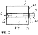
- FIGS. 1 to 3 each show an embodiment of a rotary heat exchanger device 1 with an example cubic housing 2, for example made of sheet metal or plastic, an electric drive motor 3 and a cylindrical rotary heat exchanger 4.
- the housing 2 has laterally openings (not shown) for air inlet into and out of the rotary heat exchanger 4 ,
- the drive motor 3 is disposed within the rotary heat exchanger 4, such that the axis of rotation of the rotor 32 of the drive motor 3, that is, the motor axis of rotation 31, coaxial with a rotational axis of the rotary heat exchanger 4, hereinafter heat exchanger axis of rotation 41, is.
- the rotor 32 is fixedly connected to the rotary heat exchanger 4, for example by means of a toothing or a screw connection between the rotary heat exchanger 4 and rotor 32nd
- a stator (not shown) of the drive motor 3 is fixedly connected to a side wall 21 of the housing 2, for example by means of a suitable screw connection.
- a ball bearing 6 is arranged in this for the rotatable mounting of the rotary heat exchanger 4, which is fixed to the housing 2.
- the rotational speed of the drive motor 3, and thus of the rotary heat exchanger 4 is predetermined during operation of the rotary heat exchanger device by means of suitable control electronics (not shown) and software.
- the third embodiment according to FIG. 3 differs from the two aforementioned embodiments in that the drive motor 3 is arranged outside the housing 2 and the rotor 32 is connected via suitable connecting means through the side wall 21 of the housing with the rotary heat exchanger 4.
Landscapes
- Engineering & Computer Science (AREA)
- Mechanical Engineering (AREA)
- General Engineering & Computer Science (AREA)
- Physics & Mathematics (AREA)
- Thermal Sciences (AREA)
- Chemical & Material Sciences (AREA)
- Combustion & Propulsion (AREA)
- Power Engineering (AREA)
- Heat-Exchange Devices With Radiators And Conduit Assemblies (AREA)
Claims (5)
- Dispositif échangeur de chaleur rotatif (1), en particulier destiné à être utilisé dans un dispositif de ventilation de locaux décentralisé avec récupération de chaleur, comprenant un échangeur de chaleur rotatif (4) ayant un axe de rotation d'échangeur de chaleur (41), un moteur d'entraînement (3) doté d'un stator (33) et d'un rotor (32) ayant un axe de rotation de rotor (31), et un carter (2), dans lequel l'échangeur de chaleur rotatif (4) est monté et dans lequel il tourne, caractérisé en ce que l'axe de rotation de rotor (31) et l'axe de rotation d'échangeur de chaleur (41) s'étendent de manière coaxiale et le rotor (32) est assemblé solidement avec l'échangeur de chaleur rotatif (4).
- Dispositif échangeur de chaleur rotatif selon la revendication 1, caractérisé en ce que le moteur d'entraînement (3) est disposé au moins en partie à l'intérieur de l'échangeur de chaleur rotatif (4), et le stator (22) est assemblé solidement avec le carter (2) et le rotor (32) est assemblé solidement avec l'échangeur de chaleur rotatif (4).
- Dispositif échangeur de chaleur rotatif selon la revendication 2, caractérisé en ce que le moteur d'entraînement (3) est disposé au moins en partie dans un manchon porteur (5) de l'échangeur de chaleur rotatif (4) et le rotor (32) est assemblé solidement avec le manchon porteur (5).
- Dispositif échangeur de chaleur rotatif selon la revendication 2, caractérisé en ce qu'une masse d'accumulation du rotor de l'échangeur de chaleur rotatif (4) est disposée directement sur un manchon porteur du rotor (32) du moteur d'entraînement (3).
- Dispositif échangeur de chaleur rotatif selon la revendication 1, caractérisé en ce que le moteur d'entraînement (3) est disposé en dehors du carter (2) et le rotor (32) est relié à l'échangeur de chaleur rotatif (4) à travers une paroi latérale (21) du carter (2) par des moyens de liaison appropriés.
Applications Claiming Priority (2)
| Application Number | Priority Date | Filing Date | Title |
|---|---|---|---|
| DE202014105449.9U DE202014105449U1 (de) | 2014-11-12 | 2014-11-12 | Rotationswärmetauschereinrichtung |
| PCT/DE2015/000537 WO2016074660A1 (fr) | 2014-11-12 | 2015-11-11 | Dispositif échangeur de chaleur rotatif |
Publications (2)
| Publication Number | Publication Date |
|---|---|
| EP3218663A1 EP3218663A1 (fr) | 2017-09-20 |
| EP3218663B1 true EP3218663B1 (fr) | 2019-07-24 |
Family
ID=52580391
Family Applications (1)
| Application Number | Title | Priority Date | Filing Date |
|---|---|---|---|
| EP15828812.6A Active EP3218663B1 (fr) | 2014-11-12 | 2015-11-11 | Dispositif échangeur de chaleur rotatif |
Country Status (6)
| Country | Link |
|---|---|
| US (1) | US20170328649A1 (fr) |
| EP (1) | EP3218663B1 (fr) |
| CN (1) | CN107208922B (fr) |
| DE (2) | DE202014105449U1 (fr) |
| DK (1) | DK3218663T3 (fr) |
| WO (1) | WO2016074660A1 (fr) |
Families Citing this family (38)
| Publication number | Priority date | Publication date | Assignee | Title |
|---|---|---|---|---|
| US10541070B2 (en) | 2016-04-25 | 2020-01-21 | Haier Us Appliance Solutions, Inc. | Method for forming a bed of stabilized magneto-caloric material |
| US10299655B2 (en) | 2016-05-16 | 2019-05-28 | General Electric Company | Caloric heat pump dishwasher appliance |
| US10274231B2 (en) | 2016-07-19 | 2019-04-30 | Haier Us Appliance Solutions, Inc. | Caloric heat pump system |
| US10222101B2 (en) | 2016-07-19 | 2019-03-05 | Haier Us Appliance Solutions, Inc. | Linearly-actuated magnetocaloric heat pump |
| US10281177B2 (en) | 2016-07-19 | 2019-05-07 | Haier Us Appliance Solutions, Inc. | Caloric heat pump system |
| US10295227B2 (en) | 2016-07-19 | 2019-05-21 | Haier Us Appliance Solutions, Inc. | Caloric heat pump system |
| US10443585B2 (en) | 2016-08-26 | 2019-10-15 | Haier Us Appliance Solutions, Inc. | Pump for a heat pump system |
| US10386096B2 (en) | 2016-12-06 | 2019-08-20 | Haier Us Appliance Solutions, Inc. | Magnet assembly for a magneto-caloric heat pump |
| US10288326B2 (en) | 2016-12-06 | 2019-05-14 | Haier Us Appliance Solutions, Inc. | Conduction heat pump |
| US10527325B2 (en) | 2017-03-28 | 2020-01-07 | Haier Us Appliance Solutions, Inc. | Refrigerator appliance |
| US11009282B2 (en) | 2017-03-28 | 2021-05-18 | Haier Us Appliance Solutions, Inc. | Refrigerator appliance with a caloric heat pump |
| US10451320B2 (en) | 2017-05-25 | 2019-10-22 | Haier Us Appliance Solutions, Inc. | Refrigerator appliance with water condensing features |
| US10422555B2 (en) | 2017-07-19 | 2019-09-24 | Haier Us Appliance Solutions, Inc. | Refrigerator appliance with a caloric heat pump |
| US10451322B2 (en) | 2017-07-19 | 2019-10-22 | Haier Us Appliance Solutions, Inc. | Refrigerator appliance with a caloric heat pump |
| US10520229B2 (en) | 2017-11-14 | 2019-12-31 | Haier Us Appliance Solutions, Inc. | Caloric heat pump for an appliance |
| US11022348B2 (en) | 2017-12-12 | 2021-06-01 | Haier Us Appliance Solutions, Inc. | Caloric heat pump for an appliance |
| US10557649B2 (en) | 2018-04-18 | 2020-02-11 | Haier Us Appliance Solutions, Inc. | Variable temperature magneto-caloric thermal diode assembly |
| US10641539B2 (en) | 2018-04-18 | 2020-05-05 | Haier Us Appliance Solutions, Inc. | Magneto-caloric thermal diode assembly |
| US10648705B2 (en) | 2018-04-18 | 2020-05-12 | Haier Us Appliance Solutions, Inc. | Magneto-caloric thermal diode assembly |
| US10876770B2 (en) | 2018-04-18 | 2020-12-29 | Haier Us Appliance Solutions, Inc. | Method for operating an elasto-caloric heat pump with variable pre-strain |
| US10551095B2 (en) | 2018-04-18 | 2020-02-04 | Haier Us Appliance Solutions, Inc. | Magneto-caloric thermal diode assembly |
| US10648704B2 (en) | 2018-04-18 | 2020-05-12 | Haier Us Appliance Solutions, Inc. | Magneto-caloric thermal diode assembly |
| US10830506B2 (en) | 2018-04-18 | 2020-11-10 | Haier Us Appliance Solutions, Inc. | Variable speed magneto-caloric thermal diode assembly |
| US10782051B2 (en) | 2018-04-18 | 2020-09-22 | Haier Us Appliance Solutions, Inc. | Magneto-caloric thermal diode assembly |
| US10648706B2 (en) | 2018-04-18 | 2020-05-12 | Haier Us Appliance Solutions, Inc. | Magneto-caloric thermal diode assembly with an axially pinned magneto-caloric cylinder |
| US11015842B2 (en) | 2018-05-10 | 2021-05-25 | Haier Us Appliance Solutions, Inc. | Magneto-caloric thermal diode assembly with radial polarity alignment |
| US10989449B2 (en) | 2018-05-10 | 2021-04-27 | Haier Us Appliance Solutions, Inc. | Magneto-caloric thermal diode assembly with radial supports |
| US11054176B2 (en) | 2018-05-10 | 2021-07-06 | Haier Us Appliance Solutions, Inc. | Magneto-caloric thermal diode assembly with a modular magnet system |
| US10684044B2 (en) | 2018-07-17 | 2020-06-16 | Haier Us Appliance Solutions, Inc. | Magneto-caloric thermal diode assembly with a rotating heat exchanger |
| US11092364B2 (en) | 2018-07-17 | 2021-08-17 | Haier Us Appliance Solutions, Inc. | Magneto-caloric thermal diode assembly with a heat transfer fluid circuit |
| US11193697B2 (en) | 2019-01-08 | 2021-12-07 | Haier Us Appliance Solutions, Inc. | Fan speed control method for caloric heat pump systems |
| US11149994B2 (en) | 2019-01-08 | 2021-10-19 | Haier Us Appliance Solutions, Inc. | Uneven flow valve for a caloric regenerator |
| US11168926B2 (en) | 2019-01-08 | 2021-11-09 | Haier Us Appliance Solutions, Inc. | Leveraged mechano-caloric heat pump |
| US11274860B2 (en) | 2019-01-08 | 2022-03-15 | Haier Us Appliance Solutions, Inc. | Mechano-caloric stage with inner and outer sleeves |
| US11112146B2 (en) | 2019-02-12 | 2021-09-07 | Haier Us Appliance Solutions, Inc. | Heat pump and cascaded caloric regenerator assembly |
| US11015843B2 (en) | 2019-05-29 | 2021-05-25 | Haier Us Appliance Solutions, Inc. | Caloric heat pump hydraulic system |
| CN118159800A (zh) * | 2022-05-13 | 2024-06-07 | 傲华容客有限责任公司 | 旋转再生机结构 |
| CN116255847B (zh) * | 2023-03-30 | 2023-10-20 | 江苏金凯锐科技发展有限公司 | 一种列管式换热器 |
Family Cites Families (9)
| Publication number | Priority date | Publication date | Assignee | Title |
|---|---|---|---|---|
| DE3130264A1 (de) * | 1981-07-31 | 1983-02-17 | Maico Elektroapparate-Fabrik GmbH, 7730 Villingen-Schwenningen | Antriebsvorrichtung fuer einen regenerativ-waermetauscher |
| US4711293A (en) * | 1986-08-28 | 1987-12-08 | Kabushiki Kaisha Toshiba | Ventilator of the heat exchange type |
| US5285842A (en) * | 1989-08-17 | 1994-02-15 | Stirling Technology, Inc. | Heat recovery ventilator |
| US6575228B1 (en) * | 2000-03-06 | 2003-06-10 | Mississippi State Research And Technology Corporation | Ventilating dehumidifying system |
| US6973795B1 (en) * | 2004-05-27 | 2005-12-13 | American Standard International Inc. | HVAC desiccant wheel system and method |
| WO2008034243A1 (fr) * | 2006-09-19 | 2008-03-27 | Hydrogenics Corporation | Appareil pour échanger de l'énergie et de la masse entre des courants de fluide |
| DE102008059171B4 (de) * | 2008-11-24 | 2014-08-28 | Brose Fahrzeugteile GmbH & Co. Kommanditgesellschaft, Würzburg | Antriebsmotor mit integrierter Kühlung |
| DE202009009697U1 (de) | 2009-07-15 | 2010-11-25 | Ebm-Papst Mulfingen Gmbh & Co. Kg | Antrieb für einen Rotationswärmetauscher |
| LT5829B (lt) * | 2010-09-06 | 2012-05-25 | Virginijus Rutkauskas | Decentralizuotas rekuperatorius |
-
2014
- 2014-11-12 DE DE202014105449.9U patent/DE202014105449U1/de not_active Expired - Lifetime
-
2015
- 2015-11-11 US US15/526,749 patent/US20170328649A1/en not_active Abandoned
- 2015-11-11 EP EP15828812.6A patent/EP3218663B1/fr active Active
- 2015-11-11 DK DK15828812.6T patent/DK3218663T3/da active
- 2015-11-11 WO PCT/DE2015/000537 patent/WO2016074660A1/fr active Application Filing
- 2015-11-11 CN CN201580061037.8A patent/CN107208922B/zh active Active
- 2015-11-12 DE DE102015014579.7A patent/DE102015014579A1/de not_active Withdrawn
Non-Patent Citations (1)
| Title |
|---|
| None * |
Also Published As
| Publication number | Publication date |
|---|---|
| US20170328649A1 (en) | 2017-11-16 |
| CN107208922B (zh) | 2019-12-24 |
| CN107208922A (zh) | 2017-09-26 |
| EP3218663A1 (fr) | 2017-09-20 |
| WO2016074660A1 (fr) | 2016-05-19 |
| DE202014105449U1 (de) | 2015-02-05 |
| DE102015014579A1 (de) | 2016-06-16 |
| DK3218663T3 (da) | 2019-10-14 |
Similar Documents
| Publication | Publication Date | Title |
|---|---|---|
| EP3218663B1 (fr) | Dispositif échangeur de chaleur rotatif | |
| DE10152712B4 (de) | Generator für ein Wasserkraftwerk | |
| DE102014118429A1 (de) | Lenkvorrichtung zur Verwendung in einer Solarnachführungsanlage | |
| EP3765748B1 (fr) | Groupe pompe centrifuge et procédé pour déplacer une valve dans un tel groupe pompe centrifuge | |
| DE112013007203T5 (de) | Befestigungsstruktur zum Befestigen eines angetriebenen Elements an einer Verformungswellgetriebeeinheit und Verformungswellgetriebeeinheit | |
| DE102011055599A1 (de) | Pumpe für einen Temperaturkreislauf in einem Fahrzeug | |
| CH665257A5 (de) | Vorrichtung zum veraendern des leitschaufelwinkels an einer axialen stroemungsmaschine. | |
| DE102012222602A1 (de) | Elektrische Maschine | |
| DE102009000014B4 (de) | Kupplungsvorrichtung | |
| DE202017100632U1 (de) | Antriebsanordnung für eine Fensterabschirmvorrichtung | |
| EP1945955B1 (fr) | Pompe a fluide | |
| EP2467606B1 (fr) | Découplage vibratoire d'un moteur d'entraînement | |
| DE10342812B4 (de) | Kraftübertragungssystem | |
| EP1795754B1 (fr) | Bride universelle | |
| DE102009016187B4 (de) | Lager für eine Vorrichtung zur Erzeugung eines Schwenkmoments | |
| EP3625880B1 (fr) | Ensemble de transmission et de moteur | |
| DE102016205252A1 (de) | Lageranordnung einer Motorwelle eines Elektromotors | |
| EP3118456B1 (fr) | Rotor en plastique pour pompe a vide | |
| DE102016214719A1 (de) | Bauteilverbindung | |
| DE102016207698A1 (de) | Ladeeinrichtung | |
| DE10221625A1 (de) | Vorrichtung zur Kopplung einer Gehäuseanordnung einer Kopplungseinrichtung mit einer Rotoranordnung einer Elektromaschine | |
| DE102010024962B4 (de) | Antriebsmotor für Flüssigkeitspumpe | |
| DE202014105982U1 (de) | Lenkvorrichtung zur Verwendung in einer Solarnachführungsanlage | |
| DE102017105736B4 (de) | Verstellvorrichtung für einen Verbrennungsmotor | |
| EP2965936A1 (fr) | Dispositif de commande de l'écoulement d'air à travers le refroidisseur d'un véhicule routier |
Legal Events
| Date | Code | Title | Description |
|---|---|---|---|
| STAA | Information on the status of an ep patent application or granted ep patent |
Free format text: STATUS: THE INTERNATIONAL PUBLICATION HAS BEEN MADE |
|
| PUAI | Public reference made under article 153(3) epc to a published international application that has entered the european phase |
Free format text: ORIGINAL CODE: 0009012 |
|
| STAA | Information on the status of an ep patent application or granted ep patent |
Free format text: STATUS: REQUEST FOR EXAMINATION WAS MADE |
|
| 17P | Request for examination filed |
Effective date: 20170608 |
|
| AK | Designated contracting states |
Kind code of ref document: A1 Designated state(s): AL AT BE BG CH CY CZ DE DK EE ES FI FR GB GR HR HU IE IS IT LI LT LU LV MC MK MT NL NO PL PT RO RS SE SI SK SM TR |
|
| AX | Request for extension of the european patent |
Extension state: BA ME |
|
| DAV | Request for validation of the european patent (deleted) | ||
| DAX | Request for extension of the european patent (deleted) | ||
| GRAP | Despatch of communication of intention to grant a patent |
Free format text: ORIGINAL CODE: EPIDOSNIGR1 |
|
| STAA | Information on the status of an ep patent application or granted ep patent |
Free format text: STATUS: GRANT OF PATENT IS INTENDED |
|
| INTG | Intention to grant announced |
Effective date: 20190308 |
|
| GRAS | Grant fee paid |
Free format text: ORIGINAL CODE: EPIDOSNIGR3 |
|
| GRAA | (expected) grant |
Free format text: ORIGINAL CODE: 0009210 |
|
| STAA | Information on the status of an ep patent application or granted ep patent |
Free format text: STATUS: THE PATENT HAS BEEN GRANTED |
|
| AK | Designated contracting states |
Kind code of ref document: B1 Designated state(s): AL AT BE BG CH CY CZ DE DK EE ES FI FR GB GR HR HU IE IS IT LI LT LU LV MC MK MT NL NO PL PT RO RS SE SI SK SM TR |
|
| REG | Reference to a national code |
Ref country code: GB Ref legal event code: FG4D Free format text: NOT ENGLISH |
|
| REG | Reference to a national code |
Ref country code: CH Ref legal event code: EP |
|
| REG | Reference to a national code |
Ref country code: DE Ref legal event code: R096 Ref document number: 502015009782 Country of ref document: DE |
|
| REG | Reference to a national code |
Ref country code: AT Ref legal event code: REF Ref document number: 1158699 Country of ref document: AT Kind code of ref document: T Effective date: 20190815 |
|
| REG | Reference to a national code |
Ref country code: IE Ref legal event code: FG4D Free format text: LANGUAGE OF EP DOCUMENT: GERMAN |
|
| REG | Reference to a national code |
Ref country code: CH Ref legal event code: NV Representative=s name: E. BLUM AND CO. AG PATENT- UND MARKENANWAELTE , CH |
|
| REG | Reference to a national code |
Ref country code: DK Ref legal event code: T3 Effective date: 20191010 |
|
| REG | Reference to a national code |
Ref country code: SE Ref legal event code: TRGR |
|
| REG | Reference to a national code |
Ref country code: NL Ref legal event code: MP Effective date: 20190724 |
|
| REG | Reference to a national code |
Ref country code: NO Ref legal event code: T2 Effective date: 20190724 |
|
| REG | Reference to a national code |
Ref country code: LT Ref legal event code: MG4D |
|
| PG25 | Lapsed in a contracting state [announced via postgrant information from national office to epo] |
Ref country code: FI Free format text: LAPSE BECAUSE OF FAILURE TO SUBMIT A TRANSLATION OF THE DESCRIPTION OR TO PAY THE FEE WITHIN THE PRESCRIBED TIME-LIMIT Effective date: 20190724 Ref country code: BG Free format text: LAPSE BECAUSE OF FAILURE TO SUBMIT A TRANSLATION OF THE DESCRIPTION OR TO PAY THE FEE WITHIN THE PRESCRIBED TIME-LIMIT Effective date: 20191024 Ref country code: HR Free format text: LAPSE BECAUSE OF FAILURE TO SUBMIT A TRANSLATION OF THE DESCRIPTION OR TO PAY THE FEE WITHIN THE PRESCRIBED TIME-LIMIT Effective date: 20190724 Ref country code: LT Free format text: LAPSE BECAUSE OF FAILURE TO SUBMIT A TRANSLATION OF THE DESCRIPTION OR TO PAY THE FEE WITHIN THE PRESCRIBED TIME-LIMIT Effective date: 20190724 Ref country code: NL Free format text: LAPSE BECAUSE OF FAILURE TO SUBMIT A TRANSLATION OF THE DESCRIPTION OR TO PAY THE FEE WITHIN THE PRESCRIBED TIME-LIMIT Effective date: 20190724 Ref country code: PT Free format text: LAPSE BECAUSE OF FAILURE TO SUBMIT A TRANSLATION OF THE DESCRIPTION OR TO PAY THE FEE WITHIN THE PRESCRIBED TIME-LIMIT Effective date: 20191125 |
|
| PG25 | Lapsed in a contracting state [announced via postgrant information from national office to epo] |
Ref country code: RS Free format text: LAPSE BECAUSE OF FAILURE TO SUBMIT A TRANSLATION OF THE DESCRIPTION OR TO PAY THE FEE WITHIN THE PRESCRIBED TIME-LIMIT Effective date: 20190724 Ref country code: LV Free format text: LAPSE BECAUSE OF FAILURE TO SUBMIT A TRANSLATION OF THE DESCRIPTION OR TO PAY THE FEE WITHIN THE PRESCRIBED TIME-LIMIT Effective date: 20190724 Ref country code: AL Free format text: LAPSE BECAUSE OF FAILURE TO SUBMIT A TRANSLATION OF THE DESCRIPTION OR TO PAY THE FEE WITHIN THE PRESCRIBED TIME-LIMIT Effective date: 20190724 Ref country code: GR Free format text: LAPSE BECAUSE OF FAILURE TO SUBMIT A TRANSLATION OF THE DESCRIPTION OR TO PAY THE FEE WITHIN THE PRESCRIBED TIME-LIMIT Effective date: 20191025 Ref country code: IS Free format text: LAPSE BECAUSE OF FAILURE TO SUBMIT A TRANSLATION OF THE DESCRIPTION OR TO PAY THE FEE WITHIN THE PRESCRIBED TIME-LIMIT Effective date: 20191124 |
|
| PG25 | Lapsed in a contracting state [announced via postgrant information from national office to epo] |
Ref country code: TR Free format text: LAPSE BECAUSE OF FAILURE TO SUBMIT A TRANSLATION OF THE DESCRIPTION OR TO PAY THE FEE WITHIN THE PRESCRIBED TIME-LIMIT Effective date: 20190724 |
|
| PG25 | Lapsed in a contracting state [announced via postgrant information from national office to epo] |
Ref country code: PL Free format text: LAPSE BECAUSE OF FAILURE TO SUBMIT A TRANSLATION OF THE DESCRIPTION OR TO PAY THE FEE WITHIN THE PRESCRIBED TIME-LIMIT Effective date: 20190724 Ref country code: RO Free format text: LAPSE BECAUSE OF FAILURE TO SUBMIT A TRANSLATION OF THE DESCRIPTION OR TO PAY THE FEE WITHIN THE PRESCRIBED TIME-LIMIT Effective date: 20190724 Ref country code: IT Free format text: LAPSE BECAUSE OF FAILURE TO SUBMIT A TRANSLATION OF THE DESCRIPTION OR TO PAY THE FEE WITHIN THE PRESCRIBED TIME-LIMIT Effective date: 20190724 Ref country code: EE Free format text: LAPSE BECAUSE OF FAILURE TO SUBMIT A TRANSLATION OF THE DESCRIPTION OR TO PAY THE FEE WITHIN THE PRESCRIBED TIME-LIMIT Effective date: 20190724 |
|
| PG25 | Lapsed in a contracting state [announced via postgrant information from national office to epo] |
Ref country code: SM Free format text: LAPSE BECAUSE OF FAILURE TO SUBMIT A TRANSLATION OF THE DESCRIPTION OR TO PAY THE FEE WITHIN THE PRESCRIBED TIME-LIMIT Effective date: 20190724 Ref country code: CZ Free format text: LAPSE BECAUSE OF FAILURE TO SUBMIT A TRANSLATION OF THE DESCRIPTION OR TO PAY THE FEE WITHIN THE PRESCRIBED TIME-LIMIT Effective date: 20190724 Ref country code: IS Free format text: LAPSE BECAUSE OF FAILURE TO SUBMIT A TRANSLATION OF THE DESCRIPTION OR TO PAY THE FEE WITHIN THE PRESCRIBED TIME-LIMIT Effective date: 20200224 Ref country code: SK Free format text: LAPSE BECAUSE OF FAILURE TO SUBMIT A TRANSLATION OF THE DESCRIPTION OR TO PAY THE FEE WITHIN THE PRESCRIBED TIME-LIMIT Effective date: 20190724 |
|
| REG | Reference to a national code |
Ref country code: DE Ref legal event code: R097 Ref document number: 502015009782 Country of ref document: DE |
|
| PLBE | No opposition filed within time limit |
Free format text: ORIGINAL CODE: 0009261 |
|
| STAA | Information on the status of an ep patent application or granted ep patent |
Free format text: STATUS: NO OPPOSITION FILED WITHIN TIME LIMIT |
|
| PG2D | Information on lapse in contracting state deleted |
Ref country code: IS |
|
| PG25 | Lapsed in a contracting state [announced via postgrant information from national office to epo] |
Ref country code: MC Free format text: LAPSE BECAUSE OF FAILURE TO SUBMIT A TRANSLATION OF THE DESCRIPTION OR TO PAY THE FEE WITHIN THE PRESCRIBED TIME-LIMIT Effective date: 20190724 Ref country code: LU Free format text: LAPSE BECAUSE OF NON-PAYMENT OF DUE FEES Effective date: 20191111 |
|
| 26N | No opposition filed |
Effective date: 20200603 |
|
| REG | Reference to a national code |
Ref country code: BE Ref legal event code: MM Effective date: 20191130 |
|
| PG25 | Lapsed in a contracting state [announced via postgrant information from national office to epo] |
Ref country code: SI Free format text: LAPSE BECAUSE OF FAILURE TO SUBMIT A TRANSLATION OF THE DESCRIPTION OR TO PAY THE FEE WITHIN THE PRESCRIBED TIME-LIMIT Effective date: 20190724 |
|
| PG25 | Lapsed in a contracting state [announced via postgrant information from national office to epo] |
Ref country code: IE Free format text: LAPSE BECAUSE OF NON-PAYMENT OF DUE FEES Effective date: 20191111 Ref country code: ES Free format text: LAPSE BECAUSE OF FAILURE TO SUBMIT A TRANSLATION OF THE DESCRIPTION OR TO PAY THE FEE WITHIN THE PRESCRIBED TIME-LIMIT Effective date: 20190724 |
|
| PG25 | Lapsed in a contracting state [announced via postgrant information from national office to epo] |
Ref country code: BE Free format text: LAPSE BECAUSE OF NON-PAYMENT OF DUE FEES Effective date: 20191130 |
|
| PG25 | Lapsed in a contracting state [announced via postgrant information from national office to epo] |
Ref country code: CY Free format text: LAPSE BECAUSE OF FAILURE TO SUBMIT A TRANSLATION OF THE DESCRIPTION OR TO PAY THE FEE WITHIN THE PRESCRIBED TIME-LIMIT Effective date: 20190724 |
|
| PG25 | Lapsed in a contracting state [announced via postgrant information from national office to epo] |
Ref country code: HU Free format text: LAPSE BECAUSE OF FAILURE TO SUBMIT A TRANSLATION OF THE DESCRIPTION OR TO PAY THE FEE WITHIN THE PRESCRIBED TIME-LIMIT; INVALID AB INITIO Effective date: 20151111 Ref country code: MT Free format text: LAPSE BECAUSE OF FAILURE TO SUBMIT A TRANSLATION OF THE DESCRIPTION OR TO PAY THE FEE WITHIN THE PRESCRIBED TIME-LIMIT Effective date: 20190724 |
|
| PG25 | Lapsed in a contracting state [announced via postgrant information from national office to epo] |
Ref country code: MK Free format text: LAPSE BECAUSE OF FAILURE TO SUBMIT A TRANSLATION OF THE DESCRIPTION OR TO PAY THE FEE WITHIN THE PRESCRIBED TIME-LIMIT Effective date: 20190724 |
|
| P01 | Opt-out of the competence of the unified patent court (upc) registered |
Effective date: 20230427 |
|
| PGFP | Annual fee paid to national office [announced via postgrant information from national office to epo] |
Ref country code: GB Payment date: 20231123 Year of fee payment: 9 |
|
| PGFP | Annual fee paid to national office [announced via postgrant information from national office to epo] |
Ref country code: SE Payment date: 20231123 Year of fee payment: 9 Ref country code: NO Payment date: 20231121 Year of fee payment: 9 Ref country code: FR Payment date: 20231123 Year of fee payment: 9 Ref country code: DK Payment date: 20231122 Year of fee payment: 9 Ref country code: DE Payment date: 20231128 Year of fee payment: 9 Ref country code: CH Payment date: 20231201 Year of fee payment: 9 Ref country code: AT Payment date: 20231117 Year of fee payment: 9 |