EP3218646B1 - Dispositif d'eclairage de vehicule - Google Patents
Dispositif d'eclairage de vehicule Download PDFInfo
- Publication number
- EP3218646B1 EP3218646B1 EP15797128.4A EP15797128A EP3218646B1 EP 3218646 B1 EP3218646 B1 EP 3218646B1 EP 15797128 A EP15797128 A EP 15797128A EP 3218646 B1 EP3218646 B1 EP 3218646B1
- Authority
- EP
- European Patent Office
- Prior art keywords
- circuit board
- printed circuit
- lighting device
- light
- lens
- Prior art date
- Legal status (The legal status is an assumption and is not a legal conclusion. Google has not performed a legal analysis and makes no representation as to the accuracy of the status listed.)
- Active
Links
Images
Classifications
-
- F—MECHANICAL ENGINEERING; LIGHTING; HEATING; WEAPONS; BLASTING
- F21—LIGHTING
- F21S—NON-PORTABLE LIGHTING DEVICES; SYSTEMS THEREOF; VEHICLE LIGHTING DEVICES SPECIALLY ADAPTED FOR VEHICLE EXTERIORS
- F21S41/00—Illuminating devices specially adapted for vehicle exteriors, e.g. headlamps
- F21S41/10—Illuminating devices specially adapted for vehicle exteriors, e.g. headlamps characterised by the light source
- F21S41/14—Illuminating devices specially adapted for vehicle exteriors, e.g. headlamps characterised by the light source characterised by the type of light source
- F21S41/141—Light emitting diodes [LED]
- F21S41/143—Light emitting diodes [LED] the main emission direction of the LED being parallel to the optical axis of the illuminating device
-
- F—MECHANICAL ENGINEERING; LIGHTING; HEATING; WEAPONS; BLASTING
- F21—LIGHTING
- F21S—NON-PORTABLE LIGHTING DEVICES; SYSTEMS THEREOF; VEHICLE LIGHTING DEVICES SPECIALLY ADAPTED FOR VEHICLE EXTERIORS
- F21S41/00—Illuminating devices specially adapted for vehicle exteriors, e.g. headlamps
- F21S41/20—Illuminating devices specially adapted for vehicle exteriors, e.g. headlamps characterised by refractors, transparent cover plates, light guides or filters
- F21S41/29—Attachment thereof
- F21S41/295—Attachment thereof specially adapted to projection lenses
-
- F—MECHANICAL ENGINEERING; LIGHTING; HEATING; WEAPONS; BLASTING
- F21—LIGHTING
- F21S—NON-PORTABLE LIGHTING DEVICES; SYSTEMS THEREOF; VEHICLE LIGHTING DEVICES SPECIALLY ADAPTED FOR VEHICLE EXTERIORS
- F21S45/00—Arrangements within vehicle lighting devices specially adapted for vehicle exteriors, for purposes other than emission or distribution of light
- F21S45/40—Cooling of lighting devices
- F21S45/47—Passive cooling, e.g. using fins, thermal conductive elements or openings
-
- F—MECHANICAL ENGINEERING; LIGHTING; HEATING; WEAPONS; BLASTING
- F21—LIGHTING
- F21S—NON-PORTABLE LIGHTING DEVICES; SYSTEMS THEREOF; VEHICLE LIGHTING DEVICES SPECIALLY ADAPTED FOR VEHICLE EXTERIORS
- F21S45/00—Arrangements within vehicle lighting devices specially adapted for vehicle exteriors, for purposes other than emission or distribution of light
- F21S45/60—Heating of lighting devices, e.g. for demisting
Definitions
- the present invention generally relates to a lighting device, and more specifically to a road lighting device, intended to be mounted on a motor vehicle.
- the document US20120314440 discloses a lighting device comprising a printed circuit board (also called PCB), on which LEDs are arranged, which has copper portions to evacuate the heat.
- PCB printed circuit board
- One of the known disadvantages of LEDs is to emit heat towards the back of the component, that is to say on the PCB, whereas to avoid condensation, it is advantageous to diffuse this heat towards the front. that is, the external mirror of the projector.
- This type of device is typically the one used with the ventilation system that will use the PCB heat then send it on the ice. As described above, this type of device is however very complicated.
- An object of the present invention is to meet the disadvantages of the prior art document mentioned above and in particular, first of all, to provide a lighting device for a vehicle capable of eliminating the formation of condensation on ice and simple to implement.
- a first aspect of the invention relates to a vehicle lighting device comprising at least one light source arranged to emit light, a printed circuit board on which the light source is mounted, at least one arranged lens. for receiving the light emitted by the light source and projecting a light beam to an ice of the device, and means for fixing the lens on the printed circuit board.
- a lighting device is known from the document US20110043120 .
- the fixing means is arranged to have a thermal connection between the circuit board and the lens so as to conduct the heat emitted by the printed circuit board to a space between the lens and the ice.
- the fixing means is a thermally conductive clip.
- the editing is simple.
- the light source is a light emitting diode (LED).
- LED light emitting diode
- the lighting device further comprises a mask arranged to be fixed on the printed circuit board so as to cover the printed circuit board.
- the device can be further protected, see further amplifying the phenomenon of thermal conduction forward if the mask is a thermal conductor.
- the mask has openings arranged to let the light. In this way, the mask is not an obstacle to light.
- the printed circuit board comprises a flexible portion, foldable, weakened by laser attack.
- the design of the device is flexible.
- a second aspect of the invention is a vehicle headlamp comprising a lighting device according to the first aspect of the invention.
- a third aspect of the invention is a vehicle comprising a headlamp according to the second aspect of the invention.
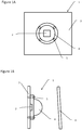
- the figures show a vehicle lighting device 1 according to the present invention.
- the lighting device 1 comprises at least one light source 2, preferably a light-emitting diode (LED), arranged to emit light, a printed circuit board 3 on which the light source 1 is mounted, at least one lens 4, for example a cross / road light lens, arranged to receive the light emitted by the light source 2 and project a light beam to an ice 6 of the lighting device 1, and a fixing means 5 of the lens 4 on the printed circuit board 3.
- LED light-emitting diode
- the fastening means 5 is a metal clip which is arranged to have a thermal connection between the printed circuit board 3 and the lens 4 so as to conduct the heat emitted by the printed circuit board 3 to a space between the lens 4 and ice cream 6.
- the device may further comprise a mask having apertures arranged to let the light through and be fixed on the printed circuit board 3 so as to cover the printed circuit board 3. Also in order to save space, it is possible to reduce the size of the PCB by folding it. For this, it achieves a weakening of a rigid area of the PCB by performing a laser attack on a portion of copper thereof, this area becomes foldable which allows to reduce the size of the PCB. It is obviously possible to make several weakened parts on the same PCB.
Landscapes
- Engineering & Computer Science (AREA)
- General Engineering & Computer Science (AREA)
- Physics & Mathematics (AREA)
- Microelectronics & Electronic Packaging (AREA)
- Optics & Photonics (AREA)
- Non-Portable Lighting Devices Or Systems Thereof (AREA)
- Arrangement Of Elements, Cooling, Sealing, Or The Like Of Lighting Devices (AREA)
Description
- La présente invention concerne de manière générale un dispositif d'éclairage, et plus précisément un dispositif d'éclairage de la route, destiné à être monté sur un véhicule automobile.
- Il est connu dans l'art antérieur des dispositifs d'éclairage de la route montés sur un véhicule automobile. Ces dispositifs font généralement partie d'un projecteur ou phare situé à l'avant du véhicule et projetant un faisceau lumineux vers l'avant du véhicule pour éclairer la route. De manière générale ces dispositifs comprennent une source de lumière, pour les éclairages à base de diode électroluminescente une carte de circuit imprimé, une lentille pour projeter la lumière émise vers l'avant et une glace située devant pour protéger le dispositif. Un problème de ces dispositifs est que la glace peut être embuée par condensation en fonction du climat et de la température extérieure. Ainsi afin d'empêcher cette condensation sur la glace, il a été trouvé d'installer un système de ventilation qui utilise la chaleur de la carte de circuit imprimé récupérée par des radiateurs situés à l'arrière de la carte pour réchauffer la glace et empêcher la condensation. Alternativement, il est commun d'appliquer un vernis anti-condensation sur la glace. Un problème de ces techniques est qu'elles ne sont pas économiques et qu'elles complexifient grandement le dispositif d'éclairage dans le cas du système de ventilation ou qu'elles ne sont pas économiques dans le cas de l'application du vernis.
- Le document
US20120314440 décrit un dispositif d'éclairage comprenant une carte de circuit imprimé (aussi appelée PCB), sur laquelle sont disposées des LED, qui possède des portions en cuivre pour évacuer la chaleur. Un des inconvénients connus des LED est d'émettre la chaleur vers l'arrière du composant, c'est-à-dire sur le PCB alors que pour éviter la condensation, il est avantageux de diffuser cette chaleur vers l'avant, c'est-à-dire la glace externe du projecteur. Ce type de dispositif est typiquement celui utilisé avec le système de ventilation qui va utiliser la chaleur du PCB puis l'envoyer par ventilation sur la glace. Comme décrit plus haut, ce type de dispositif est cependant très compliqué. - Un but de la présente invention est de répondre aux inconvénients du document de l'art antérieur mentionné ci-dessus et en particulier, tout d'abord, de fournir un dispositif d'éclairage pour un véhicule capable d'éliminer la formation de condensation sur la glace et simple à mettre en oeuvre.
- Pour cela un premier aspect de l'invention concerne un dispositif d'éclairage de véhicule comprenant au moins une source de lumière agencée pour émettre de la lumière, une carte de circuit imprimé sur laquelle est montée la source de lumière, au moins une lentille agencée pour recevoir la lumière émise par la source de lumière et projeter un faisceau lumineux vers une glace du dispositif, et un moyen de fixation de la lentille sur la carte de circuit imprimé. Un tel dispositif d'éclairage est connu du document
US20110043120 . Selon l'invention, le moyen de fixation est agencé pour présenter une liaison thermique entre la carte de circuit imprimé et la lentille de sorte à conduire de la chaleur émise par la carte de circuit imprimé vers un espace entre la lentille et la glace. Ainsi, on peut empêcher la condensation sur la glace facilement sans besoin d'élément extérieur. - Selon l'invention, le moyen de fixation est un clip thermiquement conducteur. Ainsi, le montage est simple.
- Une réalisation particulièrement intéressante consiste en ce que la source de lumière est une diode électroluminescente (LED). De cette manière, le dispositif dispose d'un rendement énergétique amélioré.
- Avantageusement, le dispositif d'éclairage comprend en outre un masque agencé pour être fixé sur la carte de circuit imprimé de manière à recouvrir la carte de circuit imprimé. Ainsi, on peut davantage protéger le dispositif, voir à amplifier encore le phénomène de conduction thermique vers l'avant si ce masque est un conducteur thermique.
- De manière avantageuse, le masque présente des ouvertures agencées pour laisser passer la lumière. De cette manière, le masque n'est pas un obstacle pour la lumière.
- Avantageusement, la carte de circuit imprimé comprend une portion souple, pliable, affaiblie par attaque laser. De cette manière, la conception du dispositif est modulable.
- Un second aspect de l'invention est un projecteur de véhicule comprenant un dispositif d'éclairage selon le premier aspect de l'invention.
- Un troisième aspect de l'invention est un véhicule comprenant un projecteur selon le second aspect de l'invention.
- D'autres caractéristiques et avantages de la présente invention apparaîtront plus clairement à la lecture de la description détaillée qui suit d'un mode de réalisation de l'invention donné à titre d'exemple nullement limitatif et illustré par les dessins annexés, dans lesquels :
- les
figures 1A et 1B représentent un dispositif d'éclairage selon un mode de réalisation de la présente invention en vue de face et de profil, respectivement. - Les figures représentent un dispositif d'éclairage de véhicule 1 selon la présente invention. Le dispositif d'éclairage 1 comprend au moins une source de lumière 2, de préférence une diode électroluminescente (LED), agencée pour émettre de la lumière, une carte de circuit imprimé 3 sur laquelle est montée la source de lumière 1, au moins une lentille 4, par exemple une lentille de feu de croisement/route, agencée pour recevoir la lumière émise par la source de lumière 2 et projeter un faisceau lumineux vers une glace 6 du dispositif d'éclairage 1, et un moyen de fixation 5 de la lentille 4 sur la carte de circuit imprimé 3.
- Le moyen de fixation 5 est un clip métallique qui est agencé pour présenter une liaison thermique entre la carte de circuit imprimé 3 et la lentille 4 de sorte à conduire de la chaleur émise par la carte de circuit 3 imprimé vers un espace entre la lentille 4 et la glace 6.
- Bien que cela ne soit pas représenté sur les figures, le dispositif peut en outre comprendre un masque présentant des ouvertures agencées pour laisser passer la lumière et être fixé sur la carte de circuit imprimé 3 de manière à recouvrir la carte de circuit imprimé 3. Egalement, afin de gagner de l'espace, il est possible de diminuer la taille du PCB en pliant celui-ci. Pour cela, on réalise un affaiblissement d'une zone rigide du PCB en exécutant une attaque laser sur une partie de cuivre de celui-ci, cette zone devient alors pliable ce qui permet de diminuer la taille du PCB. Il est évidemment possible de réaliser plusieurs parties affaiblies sur un même PCB.
- On comprendra que diverses modifications et/ou améliorations évidentes pour l'homme du métier peuvent être apportées aux différents modes de réalisation de l'invention décrits dans la présente description sans sortir du cadre de l'invention défini par les revendications annexées. En particulier, il est fait référence aux différents types de source de lumière, aux nombre de moyen de fixation et aux matériaux utilisés, etc.
Claims (7)
- Dispositif d'éclairage de véhicule (1) comprenant au moins une source de lumière (2) agencée pour émettre de la lumière, une carte de circuit imprimé (3) sur laquelle est montée la source de lumière (2), au moins une lentille (4) agencée pour recevoir la lumière émise par ladite source de lumière (2) et projeter un faisceau lumineux vers une glace (6) du dispositif, et un moyen de fixation (5) de la lentille (4) sur la carte de circuit imprimé (3), caractérisé en ce que ledit moyen de fixation (5) est un clip thermiquement conducteur agencé pour présenter une liaison thermique entre la carte de circuit imprimé (3) et la lentille (4) de sorte à conduire de la chaleur émise par la carte de circuit imprimé (3) vers un espace entre la lentille (4) et la glace (6).
- Dispositif d'éclairage selon la revendication 1, caractérisé en ce que la source de lumière (2) est une diode électroluminescente (LED).
- Dispositif d'éclairage selon l'une des revendications précédentes, caractérisé en ce qu'il comprend en outre un masque agencé pour être fixé sur la carte de circuit imprimé (3) de manière à recouvrir ladite carte de circuit imprimé.
- Dispositif d'éclairage selon la revendication 3, caractérisé en ce que ledit masque présente des ouvertures agencées pour laisser passer la lumière.
- Dispositif d'éclairage selon l'une des revendications précédentes, caractérisé en ce que la carte de circuit imprimé (3) comprend une portion souple, pliable, affaiblie par attaque laser.
- Projecteur de véhicule comportant au moins un dispositif d'éclairage selon l'une des revendications 1 à 5.
- Véhicule automobile comportant au moins un projecteur de véhicule selon la revendication 6.
Applications Claiming Priority (2)
| Application Number | Priority Date | Filing Date | Title |
|---|---|---|---|
| FR1460922A FR3028596B1 (fr) | 2014-11-13 | 2014-11-13 | Dispositif d'eclairage de vehicule |
| PCT/FR2015/052870 WO2016075382A1 (fr) | 2014-11-13 | 2015-10-23 | Dispositif d'eclairage de vehicule |
Publications (2)
| Publication Number | Publication Date |
|---|---|
| EP3218646A1 EP3218646A1 (fr) | 2017-09-20 |
| EP3218646B1 true EP3218646B1 (fr) | 2019-05-29 |
Family
ID=52477854
Family Applications (1)
| Application Number | Title | Priority Date | Filing Date |
|---|---|---|---|
| EP15797128.4A Active EP3218646B1 (fr) | 2014-11-13 | 2015-10-23 | Dispositif d'eclairage de vehicule |
Country Status (4)
| Country | Link |
|---|---|
| EP (1) | EP3218646B1 (fr) |
| CN (1) | CN107110456B (fr) |
| FR (1) | FR3028596B1 (fr) |
| WO (1) | WO2016075382A1 (fr) |
Families Citing this family (1)
| Publication number | Priority date | Publication date | Assignee | Title |
|---|---|---|---|---|
| CN109838754A (zh) * | 2017-09-08 | 2019-06-04 | 南京钧乔行汽车灯具有限公司 | 一种电加热汽车大灯灯罩 |
Family Cites Families (10)
| Publication number | Priority date | Publication date | Assignee | Title |
|---|---|---|---|---|
| JP2006140084A (ja) * | 2004-11-15 | 2006-06-01 | Koito Mfg Co Ltd | 車両用灯具 |
| US7237936B1 (en) * | 2005-05-27 | 2007-07-03 | Gibson David J | Vehicle light assembly and its associated method of manufacture |
| US8465175B2 (en) * | 2005-11-29 | 2013-06-18 | GE Lighting Solutions, LLC | LED lighting assemblies with thermal overmolding |
| KR100735325B1 (ko) * | 2006-04-17 | 2007-07-04 | 삼성전기주식회사 | 발광다이오드 패키지 및 그 제조방법 |
| KR100910054B1 (ko) * | 2007-12-18 | 2009-07-30 | 에스엘 주식회사 | Led방열 장치 |
| JP5227674B2 (ja) * | 2008-06-18 | 2013-07-03 | スタンレー電気株式会社 | 車両用灯具 |
| JP5349933B2 (ja) * | 2008-12-05 | 2013-11-20 | 株式会社小糸製作所 | 車両用灯具 |
| US8358081B2 (en) * | 2009-08-21 | 2013-01-22 | Teledyne Technologies Incorporated | Lamp assembly |
| DE102009054926B4 (de) | 2009-12-18 | 2014-08-21 | Osram Gmbh | LED-Beleuchtungsvorrichtung |
| AT512591B1 (de) * | 2012-03-12 | 2014-06-15 | Zizala Lichtsysteme Gmbh | Fahrzeugscheinwerfer mit Laserlichtquelle |
-
2014
- 2014-11-13 FR FR1460922A patent/FR3028596B1/fr not_active Expired - Fee Related
-
2015
- 2015-10-23 CN CN201580061700.4A patent/CN107110456B/zh not_active Expired - Fee Related
- 2015-10-23 WO PCT/FR2015/052870 patent/WO2016075382A1/fr not_active Ceased
- 2015-10-23 EP EP15797128.4A patent/EP3218646B1/fr active Active
Non-Patent Citations (1)
| Title |
|---|
| None * |
Also Published As
| Publication number | Publication date |
|---|---|
| EP3218646A1 (fr) | 2017-09-20 |
| FR3028596B1 (fr) | 2019-07-12 |
| CN107110456B (zh) | 2020-01-10 |
| FR3028596A1 (fr) | 2016-05-20 |
| CN107110456A (zh) | 2017-08-29 |
| WO2016075382A1 (fr) | 2016-05-19 |
Similar Documents
| Publication | Publication Date | Title |
|---|---|---|
| EP1726874B1 (fr) | Dispositif d'éclairage et/ou de signalisation à diodes électroluminescentes pour véhicule automobile | |
| KR100706063B1 (ko) | 차량용 등기구 | |
| WO2003028119A3 (fr) | Del a dissipateur thermique integre | |
| EP3073182A1 (fr) | Module lumineux pour vehicule automobile comprenant deux guides de lumiere et un radiateur comprenant deux faces de montage | |
| EP2966344B1 (fr) | Module optique a lentille pour projecteur de vehicule automobile | |
| EP1916472B1 (fr) | Dispositif d'éclairage ou de signalisation comportant deux sources lumineuses agencées sur les deux faces d'un support commun | |
| US20160348869A1 (en) | Vehicle light fixture having internal heatsink for led lamp | |
| FR2914984A1 (fr) | Support electronique flexible equipe, supportant au moins une diode electroluminescente, et procede de fabrication associe. | |
| FR3032513A1 (fr) | Agencement d'un projecteur de vehicule sans glace sur un vehicule | |
| FR3028596B1 (fr) | Dispositif d'eclairage de vehicule | |
| EP3431861B1 (fr) | Dispositif lumineux pour vehicule automobile | |
| WO2017168071A1 (fr) | Dispositif d'eclairage et/ou de signalisation lumineuse d'un vehicule automobile | |
| FR3058503A1 (fr) | Dispositif lumineux equipe d'au moins un element peltier | |
| EP3508378A1 (fr) | Dispositif d eclairage et/ou de signalisation lumineuse d'un vehicule automobile | |
| FR3022980A1 (fr) | Module optique a lentille pour vehicule automobile | |
| FR2999275A1 (fr) | Dispositif d'emission de lumiere pour projecteur de vehicule automobile et projecteur equipe dudit dispositif | |
| FR3109428A1 (fr) | Support pour un systeme lumineux, systeme lumineux comprenant un tel support, et vehicule automobile comprenant un tel systeme lumineux | |
| FR2876965A1 (fr) | Support de sources lumineuses et procede de fabrication d'assemblages de sources lumineuses avec un tel support pour dispositif d'eclairage ou de signalisation de vehicule automobile | |
| FR2806680A1 (fr) | Feu de signalisation pour vehicule | |
| EP3867563B1 (fr) | Module lumineux assurant deux fonctions photométriques présentant des signatures lumineuses distinctes | |
| EP3450841A1 (fr) | Dispositif lumineux pour vehicule automobile | |
| FR3083181A1 (fr) | Vehicule automobile comprenant deux feux de signalisation arrieres comportant chacun deux ensembles d'organes lumineux et procede de commande desdits ensembles d'organes lumineux | |
| WO2017077216A1 (fr) | Dispositif d'éclairage lumineux pour véhicule automobile | |
| WO2021044090A1 (fr) | Radiateur à capacité de refroidissement optimisée pour projecteur de véhicule automobile | |
| FR3146193A1 (fr) | Bloc optique à échangeur de chaleur à échange thermique optimisé |
Legal Events
| Date | Code | Title | Description |
|---|---|---|---|
| STAA | Information on the status of an ep patent application or granted ep patent |
Free format text: STATUS: THE INTERNATIONAL PUBLICATION HAS BEEN MADE |
|
| PUAI | Public reference made under article 153(3) epc to a published international application that has entered the european phase |
Free format text: ORIGINAL CODE: 0009012 |
|
| STAA | Information on the status of an ep patent application or granted ep patent |
Free format text: STATUS: REQUEST FOR EXAMINATION WAS MADE |
|
| 17P | Request for examination filed |
Effective date: 20170607 |
|
| AK | Designated contracting states |
Kind code of ref document: A1 Designated state(s): AL AT BE BG CH CY CZ DE DK EE ES FI FR GB GR HR HU IE IS IT LI LT LU LV MC MK MT NL NO PL PT RO RS SE SI SK SM TR |
|
| AX | Request for extension of the european patent |
Extension state: BA ME |
|
| DAV | Request for validation of the european patent (deleted) | ||
| DAX | Request for extension of the european patent (deleted) | ||
| REG | Reference to a national code |
Ref country code: DE Ref legal event code: R079 Ref document number: 602015031163 Country of ref document: DE Free format text: PREVIOUS MAIN CLASS: F21S0008100000 Ipc: F21S0041290000 |
|
| GRAP | Despatch of communication of intention to grant a patent |
Free format text: ORIGINAL CODE: EPIDOSNIGR1 |
|
| STAA | Information on the status of an ep patent application or granted ep patent |
Free format text: STATUS: GRANT OF PATENT IS INTENDED |
|
| RIC1 | Information provided on ipc code assigned before grant |
Ipc: F21S 45/60 20180101ALI20181130BHEP Ipc: F21S 45/47 20180101ALI20181130BHEP Ipc: F21S 41/29 20180101AFI20181130BHEP Ipc: F21Y 115/10 20160101ALN20181130BHEP |
|
| INTG | Intention to grant announced |
Effective date: 20190108 |
|
| RIC1 | Information provided on ipc code assigned before grant |
Ipc: F21Y 115/10 20160101ALN20181130BHEP Ipc: F21S 45/47 20180101ALI20181130BHEP Ipc: F21S 45/60 20180101ALI20181130BHEP Ipc: F21S 41/29 20180101AFI20181130BHEP |
|
| GRAS | Grant fee paid |
Free format text: ORIGINAL CODE: EPIDOSNIGR3 |
|
| GRAA | (expected) grant |
Free format text: ORIGINAL CODE: 0009210 |
|
| STAA | Information on the status of an ep patent application or granted ep patent |
Free format text: STATUS: THE PATENT HAS BEEN GRANTED |
|
| AK | Designated contracting states |
Kind code of ref document: B1 Designated state(s): AL AT BE BG CH CY CZ DE DK EE ES FI FR GB GR HR HU IE IS IT LI LT LU LV MC MK MT NL NO PL PT RO RS SE SI SK SM TR |
|
| REG | Reference to a national code |
Ref country code: GB Ref legal event code: FG4D Free format text: NOT ENGLISH |
|
| REG | Reference to a national code |
Ref country code: CH Ref legal event code: EP |
|
| REG | Reference to a national code |
Ref country code: DE Ref legal event code: R084 Ref document number: 602015031163 Country of ref document: DE |
|
| REG | Reference to a national code |
Ref country code: AT Ref legal event code: REF Ref document number: 1138467 Country of ref document: AT Kind code of ref document: T Effective date: 20190615 |
|
| REG | Reference to a national code |
Ref country code: DE Ref legal event code: R096 Ref document number: 602015031163 Country of ref document: DE |
|
| REG | Reference to a national code |
Ref country code: IE Ref legal event code: FG4D Free format text: LANGUAGE OF EP DOCUMENT: FRENCH |
|
| REG | Reference to a national code |
Ref country code: GB Ref legal event code: 746 Effective date: 20190617 |
|
| REG | Reference to a national code |
Ref country code: NL Ref legal event code: MP Effective date: 20190529 |
|
| REG | Reference to a national code |
Ref country code: LT Ref legal event code: MG4D |
|
| PG25 | Lapsed in a contracting state [announced via postgrant information from national office to epo] |
Ref country code: HR Free format text: LAPSE BECAUSE OF FAILURE TO SUBMIT A TRANSLATION OF THE DESCRIPTION OR TO PAY THE FEE WITHIN THE PRESCRIBED TIME-LIMIT Effective date: 20190529 Ref country code: SE Free format text: LAPSE BECAUSE OF FAILURE TO SUBMIT A TRANSLATION OF THE DESCRIPTION OR TO PAY THE FEE WITHIN THE PRESCRIBED TIME-LIMIT Effective date: 20190529 Ref country code: FI Free format text: LAPSE BECAUSE OF FAILURE TO SUBMIT A TRANSLATION OF THE DESCRIPTION OR TO PAY THE FEE WITHIN THE PRESCRIBED TIME-LIMIT Effective date: 20190529 Ref country code: NO Free format text: LAPSE BECAUSE OF FAILURE TO SUBMIT A TRANSLATION OF THE DESCRIPTION OR TO PAY THE FEE WITHIN THE PRESCRIBED TIME-LIMIT Effective date: 20190829 Ref country code: AL Free format text: LAPSE BECAUSE OF FAILURE TO SUBMIT A TRANSLATION OF THE DESCRIPTION OR TO PAY THE FEE WITHIN THE PRESCRIBED TIME-LIMIT Effective date: 20190529 Ref country code: ES Free format text: LAPSE BECAUSE OF FAILURE TO SUBMIT A TRANSLATION OF THE DESCRIPTION OR TO PAY THE FEE WITHIN THE PRESCRIBED TIME-LIMIT Effective date: 20190529 Ref country code: LT Free format text: LAPSE BECAUSE OF FAILURE TO SUBMIT A TRANSLATION OF THE DESCRIPTION OR TO PAY THE FEE WITHIN THE PRESCRIBED TIME-LIMIT Effective date: 20190529 Ref country code: PT Free format text: LAPSE BECAUSE OF FAILURE TO SUBMIT A TRANSLATION OF THE DESCRIPTION OR TO PAY THE FEE WITHIN THE PRESCRIBED TIME-LIMIT Effective date: 20190930 |
|
| PG25 | Lapsed in a contracting state [announced via postgrant information from national office to epo] |
Ref country code: BG Free format text: LAPSE BECAUSE OF FAILURE TO SUBMIT A TRANSLATION OF THE DESCRIPTION OR TO PAY THE FEE WITHIN THE PRESCRIBED TIME-LIMIT Effective date: 20190829 Ref country code: GR Free format text: LAPSE BECAUSE OF FAILURE TO SUBMIT A TRANSLATION OF THE DESCRIPTION OR TO PAY THE FEE WITHIN THE PRESCRIBED TIME-LIMIT Effective date: 20190830 Ref country code: RS Free format text: LAPSE BECAUSE OF FAILURE TO SUBMIT A TRANSLATION OF THE DESCRIPTION OR TO PAY THE FEE WITHIN THE PRESCRIBED TIME-LIMIT Effective date: 20190529 Ref country code: LV Free format text: LAPSE BECAUSE OF FAILURE TO SUBMIT A TRANSLATION OF THE DESCRIPTION OR TO PAY THE FEE WITHIN THE PRESCRIBED TIME-LIMIT Effective date: 20190529 |
|
| REG | Reference to a national code |
Ref country code: AT Ref legal event code: MK05 Ref document number: 1138467 Country of ref document: AT Kind code of ref document: T Effective date: 20190529 |
|
| PG25 | Lapsed in a contracting state [announced via postgrant information from national office to epo] |
Ref country code: EE Free format text: LAPSE BECAUSE OF FAILURE TO SUBMIT A TRANSLATION OF THE DESCRIPTION OR TO PAY THE FEE WITHIN THE PRESCRIBED TIME-LIMIT Effective date: 20190529 Ref country code: DK Free format text: LAPSE BECAUSE OF FAILURE TO SUBMIT A TRANSLATION OF THE DESCRIPTION OR TO PAY THE FEE WITHIN THE PRESCRIBED TIME-LIMIT Effective date: 20190529 Ref country code: NL Free format text: LAPSE BECAUSE OF FAILURE TO SUBMIT A TRANSLATION OF THE DESCRIPTION OR TO PAY THE FEE WITHIN THE PRESCRIBED TIME-LIMIT Effective date: 20190529 Ref country code: RO Free format text: LAPSE BECAUSE OF FAILURE TO SUBMIT A TRANSLATION OF THE DESCRIPTION OR TO PAY THE FEE WITHIN THE PRESCRIBED TIME-LIMIT Effective date: 20190529 Ref country code: AT Free format text: LAPSE BECAUSE OF FAILURE TO SUBMIT A TRANSLATION OF THE DESCRIPTION OR TO PAY THE FEE WITHIN THE PRESCRIBED TIME-LIMIT Effective date: 20190529 Ref country code: CZ Free format text: LAPSE BECAUSE OF FAILURE TO SUBMIT A TRANSLATION OF THE DESCRIPTION OR TO PAY THE FEE WITHIN THE PRESCRIBED TIME-LIMIT Effective date: 20190529 Ref country code: SK Free format text: LAPSE BECAUSE OF FAILURE TO SUBMIT A TRANSLATION OF THE DESCRIPTION OR TO PAY THE FEE WITHIN THE PRESCRIBED TIME-LIMIT Effective date: 20190529 |
|
| PG25 | Lapsed in a contracting state [announced via postgrant information from national office to epo] |
Ref country code: SM Free format text: LAPSE BECAUSE OF FAILURE TO SUBMIT A TRANSLATION OF THE DESCRIPTION OR TO PAY THE FEE WITHIN THE PRESCRIBED TIME-LIMIT Effective date: 20190529 Ref country code: IT Free format text: LAPSE BECAUSE OF FAILURE TO SUBMIT A TRANSLATION OF THE DESCRIPTION OR TO PAY THE FEE WITHIN THE PRESCRIBED TIME-LIMIT Effective date: 20190529 |
|
| REG | Reference to a national code |
Ref country code: DE Ref legal event code: R097 Ref document number: 602015031163 Country of ref document: DE |
|
| PG25 | Lapsed in a contracting state [announced via postgrant information from national office to epo] |
Ref country code: TR Free format text: LAPSE BECAUSE OF FAILURE TO SUBMIT A TRANSLATION OF THE DESCRIPTION OR TO PAY THE FEE WITHIN THE PRESCRIBED TIME-LIMIT Effective date: 20190529 |
|
| PLBE | No opposition filed within time limit |
Free format text: ORIGINAL CODE: 0009261 |
|
| STAA | Information on the status of an ep patent application or granted ep patent |
Free format text: STATUS: NO OPPOSITION FILED WITHIN TIME LIMIT |
|
| PG25 | Lapsed in a contracting state [announced via postgrant information from national office to epo] |
Ref country code: PL Free format text: LAPSE BECAUSE OF FAILURE TO SUBMIT A TRANSLATION OF THE DESCRIPTION OR TO PAY THE FEE WITHIN THE PRESCRIBED TIME-LIMIT Effective date: 20190529 |
|
| 26N | No opposition filed |
Effective date: 20200303 |
|
| PG25 | Lapsed in a contracting state [announced via postgrant information from national office to epo] |
Ref country code: SI Free format text: LAPSE BECAUSE OF FAILURE TO SUBMIT A TRANSLATION OF THE DESCRIPTION OR TO PAY THE FEE WITHIN THE PRESCRIBED TIME-LIMIT Effective date: 20190529 Ref country code: MC Free format text: LAPSE BECAUSE OF FAILURE TO SUBMIT A TRANSLATION OF THE DESCRIPTION OR TO PAY THE FEE WITHIN THE PRESCRIBED TIME-LIMIT Effective date: 20190529 |
|
| REG | Reference to a national code |
Ref country code: CH Ref legal event code: PL |
|
| PG25 | Lapsed in a contracting state [announced via postgrant information from national office to epo] |
Ref country code: CH Free format text: LAPSE BECAUSE OF NON-PAYMENT OF DUE FEES Effective date: 20191031 Ref country code: LU Free format text: LAPSE BECAUSE OF NON-PAYMENT OF DUE FEES Effective date: 20191023 Ref country code: LI Free format text: LAPSE BECAUSE OF NON-PAYMENT OF DUE FEES Effective date: 20191031 |
|
| REG | Reference to a national code |
Ref country code: BE Ref legal event code: MM Effective date: 20191031 |
|
| PG25 | Lapsed in a contracting state [announced via postgrant information from national office to epo] |
Ref country code: BE Free format text: LAPSE BECAUSE OF NON-PAYMENT OF DUE FEES Effective date: 20191031 |
|
| PG25 | Lapsed in a contracting state [announced via postgrant information from national office to epo] |
Ref country code: IE Free format text: LAPSE BECAUSE OF NON-PAYMENT OF DUE FEES Effective date: 20191023 |
|
| PG25 | Lapsed in a contracting state [announced via postgrant information from national office to epo] |
Ref country code: CY Free format text: LAPSE BECAUSE OF FAILURE TO SUBMIT A TRANSLATION OF THE DESCRIPTION OR TO PAY THE FEE WITHIN THE PRESCRIBED TIME-LIMIT Effective date: 20190529 |
|
| PG25 | Lapsed in a contracting state [announced via postgrant information from national office to epo] |
Ref country code: IS Free format text: LAPSE BECAUSE OF FAILURE TO SUBMIT A TRANSLATION OF THE DESCRIPTION OR TO PAY THE FEE WITHIN THE PRESCRIBED TIME-LIMIT Effective date: 20190929 |
|
| PG25 | Lapsed in a contracting state [announced via postgrant information from national office to epo] |
Ref country code: HU Free format text: LAPSE BECAUSE OF FAILURE TO SUBMIT A TRANSLATION OF THE DESCRIPTION OR TO PAY THE FEE WITHIN THE PRESCRIBED TIME-LIMIT; INVALID AB INITIO Effective date: 20151023 Ref country code: MT Free format text: LAPSE BECAUSE OF FAILURE TO SUBMIT A TRANSLATION OF THE DESCRIPTION OR TO PAY THE FEE WITHIN THE PRESCRIBED TIME-LIMIT Effective date: 20190529 |
|
| PG25 | Lapsed in a contracting state [announced via postgrant information from national office to epo] |
Ref country code: MK Free format text: LAPSE BECAUSE OF FAILURE TO SUBMIT A TRANSLATION OF THE DESCRIPTION OR TO PAY THE FEE WITHIN THE PRESCRIBED TIME-LIMIT Effective date: 20190529 |
|
| REG | Reference to a national code |
Ref country code: DE Ref legal event code: R081 Ref document number: 602015031163 Country of ref document: DE Owner name: STELLANTIS AUTO SAS, FR Free format text: FORMER OWNER: PSA AUTOMOBILES SA, POISSY, FR |
|
| PGFP | Annual fee paid to national office [announced via postgrant information from national office to epo] |
Ref country code: GB Payment date: 20250923 Year of fee payment: 11 |
|
| PGFP | Annual fee paid to national office [announced via postgrant information from national office to epo] |
Ref country code: FR Payment date: 20250923 Year of fee payment: 11 |
|
| PGFP | Annual fee paid to national office [announced via postgrant information from national office to epo] |
Ref country code: DE Payment date: 20250923 Year of fee payment: 11 |