EP3217901B1 - Vorrichtung zum verspannen von wirbeln der menschlichen wirbelsäule - Google Patents
Vorrichtung zum verspannen von wirbeln der menschlichen wirbelsäule Download PDFInfo
- Publication number
- EP3217901B1 EP3217901B1 EP15732667.9A EP15732667A EP3217901B1 EP 3217901 B1 EP3217901 B1 EP 3217901B1 EP 15732667 A EP15732667 A EP 15732667A EP 3217901 B1 EP3217901 B1 EP 3217901B1
- Authority
- EP
- European Patent Office
- Prior art keywords
- pedicle
- head
- screw
- rod
- safety
- Prior art date
- Legal status (The legal status is an assumption and is not a legal conclusion. Google has not performed a legal analysis and makes no representation as to the accuracy of the status listed.)
- Active
Links
Images








Classifications
-
- A—HUMAN NECESSITIES
- A61—MEDICAL OR VETERINARY SCIENCE; HYGIENE
- A61B—DIAGNOSIS; SURGERY; IDENTIFICATION
- A61B17/00—Surgical instruments, devices or methods
- A61B17/56—Surgical instruments or methods for treatment of bones or joints; Devices specially adapted therefor
- A61B17/58—Surgical instruments or methods for treatment of bones or joints; Devices specially adapted therefor for osteosynthesis, e.g. bone plates, screws or setting implements
- A61B17/68—Internal fixation devices, including fasteners and spinal fixators, even if a part thereof projects from the skin
- A61B17/70—Spinal positioners or stabilisers, e.g. stabilisers comprising fluid filler in an implant
- A61B17/7001—Screws or hooks combined with longitudinal elements which do not contact vertebrae
- A61B17/7002—Longitudinal elements, e.g. rods
- A61B17/7004—Longitudinal elements, e.g. rods with a cross-section which varies along its length
- A61B17/7005—Parts of the longitudinal elements, e.g. their ends, being specially adapted to fit in the screw or hook heads
-
- A—HUMAN NECESSITIES
- A61—MEDICAL OR VETERINARY SCIENCE; HYGIENE
- A61B—DIAGNOSIS; SURGERY; IDENTIFICATION
- A61B17/00—Surgical instruments, devices or methods
- A61B17/56—Surgical instruments or methods for treatment of bones or joints; Devices specially adapted therefor
- A61B17/58—Surgical instruments or methods for treatment of bones or joints; Devices specially adapted therefor for osteosynthesis, e.g. bone plates, screws or setting implements
- A61B17/68—Internal fixation devices, including fasteners and spinal fixators, even if a part thereof projects from the skin
- A61B17/70—Spinal positioners or stabilisers, e.g. stabilisers comprising fluid filler in an implant
- A61B17/7001—Screws or hooks combined with longitudinal elements which do not contact vertebrae
- A61B17/7002—Longitudinal elements, e.g. rods
-
- A—HUMAN NECESSITIES
- A61—MEDICAL OR VETERINARY SCIENCE; HYGIENE
- A61B—DIAGNOSIS; SURGERY; IDENTIFICATION
- A61B17/00—Surgical instruments, devices or methods
- A61B17/56—Surgical instruments or methods for treatment of bones or joints; Devices specially adapted therefor
- A61B17/58—Surgical instruments or methods for treatment of bones or joints; Devices specially adapted therefor for osteosynthesis, e.g. bone plates, screws or setting implements
- A61B17/68—Internal fixation devices, including fasteners and spinal fixators, even if a part thereof projects from the skin
- A61B17/70—Spinal positioners or stabilisers, e.g. stabilisers comprising fluid filler in an implant
- A61B17/7001—Screws or hooks combined with longitudinal elements which do not contact vertebrae
- A61B17/7002—Longitudinal elements, e.g. rods
- A61B17/7004—Longitudinal elements, e.g. rods with a cross-section which varies along its length
-
- A—HUMAN NECESSITIES
- A61—MEDICAL OR VETERINARY SCIENCE; HYGIENE
- A61B—DIAGNOSIS; SURGERY; IDENTIFICATION
- A61B17/00—Surgical instruments, devices or methods
- A61B17/56—Surgical instruments or methods for treatment of bones or joints; Devices specially adapted therefor
- A61B17/58—Surgical instruments or methods for treatment of bones or joints; Devices specially adapted therefor for osteosynthesis, e.g. bone plates, screws or setting implements
- A61B17/68—Internal fixation devices, including fasteners and spinal fixators, even if a part thereof projects from the skin
- A61B17/70—Spinal positioners or stabilisers, e.g. stabilisers comprising fluid filler in an implant
- A61B17/7001—Screws or hooks combined with longitudinal elements which do not contact vertebrae
- A61B17/7002—Longitudinal elements, e.g. rods
- A61B17/701—Longitudinal elements with a non-circular, e.g. rectangular, cross-section
-
- A—HUMAN NECESSITIES
- A61—MEDICAL OR VETERINARY SCIENCE; HYGIENE
- A61B—DIAGNOSIS; SURGERY; IDENTIFICATION
- A61B17/00—Surgical instruments, devices or methods
- A61B17/56—Surgical instruments or methods for treatment of bones or joints; Devices specially adapted therefor
- A61B17/58—Surgical instruments or methods for treatment of bones or joints; Devices specially adapted therefor for osteosynthesis, e.g. bone plates, screws or setting implements
- A61B17/68—Internal fixation devices, including fasteners and spinal fixators, even if a part thereof projects from the skin
- A61B17/70—Spinal positioners or stabilisers, e.g. stabilisers comprising fluid filler in an implant
- A61B17/7001—Screws or hooks combined with longitudinal elements which do not contact vertebrae
- A61B17/7032—Screws or hooks with U-shaped head or back through which longitudinal rods pass
-
- A—HUMAN NECESSITIES
- A61—MEDICAL OR VETERINARY SCIENCE; HYGIENE
- A61B—DIAGNOSIS; SURGERY; IDENTIFICATION
- A61B17/00—Surgical instruments, devices or methods
- A61B17/56—Surgical instruments or methods for treatment of bones or joints; Devices specially adapted therefor
- A61B17/58—Surgical instruments or methods for treatment of bones or joints; Devices specially adapted therefor for osteosynthesis, e.g. bone plates, screws or setting implements
- A61B17/68—Internal fixation devices, including fasteners and spinal fixators, even if a part thereof projects from the skin
- A61B17/70—Spinal positioners or stabilisers, e.g. stabilisers comprising fluid filler in an implant
- A61B17/7001—Screws or hooks combined with longitudinal elements which do not contact vertebrae
- A61B17/7035—Screws or hooks, wherein a rod-clamping part and a bone-anchoring part can pivot relative to each other
- A61B17/7037—Screws or hooks, wherein a rod-clamping part and a bone-anchoring part can pivot relative to each other wherein pivoting is blocked when the rod is clamped
Definitions
- the annular head has a through-opening slot with female threaded portions.
- a locking screw can be screwed, which secures a insertable into the slot in the head of the pedicle screw bar.
- the WO 94/26191 shows an osteosynthesis device with a bone screw, in particular a pedicle screw, with a groove having a clevis and mounted in the groove of the clevis correction rod, which is secured against rotation by structuring its outer surface.
- Another such device shows the DE 692 06 318 T2 , Furthermore, on the WO 93/11715 A1 , the WO 92/20294 A1 , the WO 91/16020 A1 and the DE 92 02 745 U1 directed. Furthermore, from the US 2012/0083850 A1 a device according to the preamble of claim 1 known. Furthermore, the shows US 2012/0035670 A1 a device with a multi-part construction.
- the invention has for its object to provide a device of the type mentioned for clamping vertebrae of the spine, which has a high dimensional stability with a simple structure and simple, reliable applicability and is secured against loosening or dislocations of individual components.
- the invention thus shows a device for clamping vertebrae of the human spine, with at least one pedicle screw whose head is at least partially spherical and is received in an at least partially spherical bearing area of a pedicle head, wherein the pedicle head has a central recess, which Bearing area comprises, as well as a transverse to the central recess arranged slot for receiving a rod and the storage area opposite in the central recess formed internal thread, in which for clamping the rod a locking screw is arranged, wherein the locking screw on its side facing the rod with a Is provided against rotation.
- the invention thus provides a construction in which a locking screw is screwed into a pedicle head to clamp a rod.
- the rod is received in a slot of the pedicle head and is biased by the locking screw against the end of the slot of the pedicle head.
- the anti-rotation device according to the invention.
- This comprises in a preferred embodiment of the invention on the end face of the locking screw substantially radially arranged elevations and convex areas.
- the locking screw thus locked on the surface of the rod, whereby unintentional release of the locking screw is prevented.
- According to the invention thus takes place a positive engagement between the frontal surface of the locking screw and the surface of the rod.
- This positive locking is easily possible when screwing the locking screw with the appropriate force and taking into account the elasticity of the materials used. In the assembled state, however, there is a bias, which reliably prevents unintentional rotation of the locking screw by the positive locking between the front surface and the rod.
- the frontal surface of the locking screw according to the invention may be provided in different form with the elevations and concave areas, for example in multiple pitch, so that around the circumference of the front side, based on the axis of rotation of the locking screw star-shaped radial projections and radial concave areas are formed.
- the structuring of these elevations and concave areas may be rounded, but it is also possible to provide them with a trapezoidal cross-section, with a bead-like cross-section, beveled, or provided with a triangular cross-section.
- the invention is provided in a favorable development that the rod is smooth or roughened or textured on its surface.
- the rod can securely engage in the positive radial projections or radial concave portions of the locking screw.
- a roughened embodiment of the surface results in an additional frictional force, in addition to or in addition to the positive locking with the locking screw leads.
- the Fig. 1 shows a perspective view of a device according to the invention in the mounted state.
- a plurality of pedicle screws 1 are shown, which are oriented in different directions, as it is when screwed into a spinal column.
- the pedicle screws are provided with a thread 16, as in particular hereinafter in connection with Fig. 11 is described.
- the pedicle screws At its upper end, the pedicle screws have a head 2 (s. Fig. 11 ), which is provided with a spherical region 3.
- the pedicle screws 1 are each guided by a central recess of a pedicle head 5.
- the pedicle head 5 has a slot 7, in which a rod 8 is inserted.
- a locking screw 10 whose thread engages in an internal thread 9 of the pedicle head 5.
- the internal thread 9 is in a central recess 6 (s. Fig. 9 ) of the pedicle head 5 is formed.
- the inventive design of the locking screw 10 results in a positive locking with the rod 8, as will be explained in detail below.
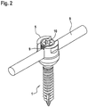
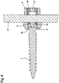
- the Fig. 2 shows an enlarged perspective view in the mounted state. From the representations of Fig. 3 and 4 , which each show an axial section along the longitudinal axis of the pedicle screw 4, results in the assignment of the individual components in the assembled state, the view of the Fig. 3 and 4 are each rotated by 90 ° to each other.
- the pedicle screws 1 have at their head 2 a horringriffsaus originallyung 14, s. also Fig. 11 ,
- the thread is designed as a compression thread and has a variable pitch in the conical core diameter and constant sharp thread crests over the entire screw length. This is also evident from the presentation of the Fig. 11 ,
- the spherical region 3 of the head 2 is roughened on its surface, for example by circumferential grooves or the like.
- the pedicle screw 1, and in particular its head 2 are performed or pushed through the central recess 6 of the pedicle head 4.
- the central recess 6 of the pedicle head 4 is provided with a spherical bearing area 4, which is formed to match the spherical portion 3 of the head 2 of the pedicle screw 1.
- the spherical portion 3 is in surface contact with the spherical bearing portion 4, whereby relative movements between the pedicle head 5 and the pedicle screw 1 are prevented in the clamped state.
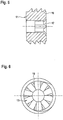
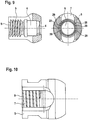
- the design of the pedicle head 5 results in particular from the FIGS. 9 and 10 , From the frontal view of the Fig. 9 (right representation according to Fig. 9 ), the slot 7 of the pedicle head 5 is clearly visible.
- a securing sleeve 12 Adjacent to the head 2 of the pedicle screw 1, a securing sleeve 12 is arranged in the central recess 6, which hereinafter in connection with the FIGS. 7 and 8 will be described.
- a rod 8 is inserted, as can be seen from the Fig. 1 and 2 results.
- the rod 8 will be described below in connection with Fig. 19-25 explained in more detail.
- the locking screw 10 For clamping the rod 8 is the locking screw 10, which is provided with a horringriffsaus supraung 17, for example, a polygon or a hexagon profile.
- the locking screw 10 is provided on its front side, which faces the rod 8, with a rotation 11.
- This includes alternately arranged radial elevations 18 and radial concave areas 19. It thus results in a star-like configuration of the front side, s. especially Fig. 6 and 12 to 18 ,
- the radial elevations 18 and the radial concave areas 19 are arranged alternately with respect to one another and, when the securing screw 10 is screwed in, lead to a positive locking engagement with the rod 8.
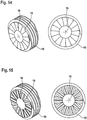
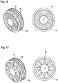
- FIGS. 12 to 18 each show a perspective view in the left-hand illustration and an end-side view in the right-hand illustration, analogously Fig. 6 ,
- Fig. 12 is a 7-division planned
- the Fig. 6 shows a 10s division, similar Fig. 13
- Fig. 14 a 15-division is provided.
- the Radial elevations 18 and the radial concave portions 19 may be formed in different ways, as can be seen from the Fig. 15-18 results.
- These exemplary embodiments show the radial elevations or radial concave areas 18, 19 in different cross-sectional configurations, namely in FIG Fig.
- the locking sleeve 12 is, as is also out Fig. 3 results, inserted into the central recess 6 of the pedicle head 5.
- the locking sleeve 12 has, as in the FIGS. 7 and 8 shown, a central recess 20 into which the rod 8 can be inserted.
- the securing sleeve 12 is provided with a slot 21, which is provided with a substantially cylindrical portion 22.
- the area of the securing sleeve 12 facing the head 2 of the pedicle screw 1 is provided with a spherical bearing area 13 (see FIG. Fig.
- the locking sleeve 12 is provided at its end with locking lugs 23 which engage in corresponding recesses 28 of the central recess 6 of the pedicle head 5 to the pedicle head 5 after insertion of the pedicle screw. 2 to be held captive on this before the rod 8 is mounted in the further assembly process.
- the recesses 28 are formed as part of an annular groove which is formed in the wall of the central recess 6 of the pedicle head 5.
- the locking lugs 23 engage.
- the wall of the recess 28 is provided with a structuring 29. This can be formed by regions of different radius and thus different depth of the annular groove 28.
- the locking sleeve 12 is mounted with an axial clearance in the pedicle head 5, so that upon pressing the rod 8 by means of the locking screw 10, the locking sleeve 12 biased in the central recess 6 of the pedicle 5 against the spherical bearing portion 3 of the head 2 of the pedicle screw 1 can be to tighten the head 2 within the pedicle head 5 against rotation.
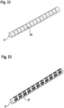
- the Fig. 19-25 show different embodiments of the inventive rod 8. This can be smooth and cylindrical ( Fig. 19 ). However, it is also possible to provide individual flattened surface segments 24, which are distributed around the circumference and in the longitudinal direction of the rod 8 ( Fig. 20 ).
- the Fig. 21 shows an embodiment with continuous surfaces 25th
- Fig. 22 an embodiment is shown in which at the periphery of the rod 8 spherical elements 26 are formed.
- the Fig. 23 shows a modification in which grooved segments 27 are provided. From Fig. 28, an embodiment can be seen in which a profiled cross-section of the rod 8 is provided, s. right half of Fig. 24 ,
- the Fig. 25 shows an embodiment in which different Cross-sections are provided, depending on the location of the rod 8.
Landscapes
- Health & Medical Sciences (AREA)
- Orthopedic Medicine & Surgery (AREA)
- Life Sciences & Earth Sciences (AREA)
- Neurology (AREA)
- Surgery (AREA)
- Heart & Thoracic Surgery (AREA)
- Engineering & Computer Science (AREA)
- Biomedical Technology (AREA)
- Nuclear Medicine, Radiotherapy & Molecular Imaging (AREA)
- Medical Informatics (AREA)
- Molecular Biology (AREA)
- Animal Behavior & Ethology (AREA)
- General Health & Medical Sciences (AREA)
- Public Health (AREA)
- Veterinary Medicine (AREA)
- Surgical Instruments (AREA)
Description
- Aus der
DE 92 02 745 U1 ist eine Vorrichtung zum Verspannen von Wirbeln der menschlichen Wirbelsäule mit mindestens zwei Pedikelschrauben bekannt, deren ringförmiger Kopf einen zur Öffnung hin durchgehenden Schlitz mit Innengewindeabschnitten aufweist. In dem Schlitz ist eine Sicherungsschraube einschraubbar, welche einen in den Schlitz im Kopf der Pedikelschraube einlegbaren Stab sichert. - Die
WO 94/26191 - Eine weitere derartige Vorrichtung zeigt die
DE 692 06 318 T2 . Weiterhin wird auf dieWO 93/11715 A1 WO 92/20294 A1 WO 91/16020 A1 DE 92 02 745 U1 verwiesen. Ferner ist aus derUS 2012/0083850 A1 eine Vorrichtung gemäß dem Oberbegriff des Anspruchs 1 bekannt. Ferner zeigt dieUS 2012/0035670 A1 eine Vorrichtung mit einem mehrteiligen Aufbau. - Bei derartigen Vorrichtungen zum Verspannen von Wirbeln, welche intern, im Körper des Patienten eingesetzt werden, ist es erforderlich, Maßnahmen zu treffen, dass die vom Operateur vorgewählten Einstellungen der Vorrichtung dauerhaft beibehalten werden und sich nicht durch Bewegungen des Körpers ändern können.
- Der Erfindung liegt die Aufgabe zugrunde, eine Vorrichtung der eingangs genannten Art zum Verspannen von Wirbeln der Wirbelsäule zu schaffen, welche bei einfachem Aufbau und einfacher, betriebssicherer Anwendbarkeit eine hohe Formstabilität aufweist und gegen Lockerungen oder Versetzungen einzelner Bauelemente gesichert ist.
- Erfindungsgemäß wird die Aufgabe durch die Merkmalskombination des Anspruchs 1 gelöst, die Unteransprüche zeigen weitere vorteilhafte Ausgestaltungen der Erfindung.
- Die Erfindung zeigt somit eine Vorrichtung zum Verspannen von Wirbeln der menschlichen Wirbelsäule, mit zumindest einer Pedikelschraube, deren Kopf zumindest zum Teil sphärisch ausgebildet ist und in einem zumindest zum Teil sphärischen Lagerbereich eines Pedikelkopfes aufgenommen ist, wobei der Pedikelkopf eine zentrische Ausnehmung aufweist, welche den Lagerbereich umfasst, sowie einen quer zu der zentrischen Ausnehmung angeordneten Schlitz zur Aufnahme eines Stabs und einem dem Lagerbereich gegenüberliegend in der zentrischen Ausnehmung ausgebildeten Innengewinde, in welchem zur Klemmung des Stabs eine Sicherungsschraube angeordnet ist, wobei die Sicherungsschraube an ihrer dem Stab zugewandten Seite mit einer Verdrehsicherung versehen ist.
- Die Erfindung sieht somit eine Konstruktion vor, bei welcher eine Sicherungsschraube in einem Pedikelkopf eingeschraubt wird, um einen Stab zu klemmen. Der Stab ist in einem Schlitz des Pedikelkopfes aufgenommen und wird mittels der Sicherungsschraube gegen das Ende des Schlitzes des Pedikelkopfes vorgespannt.
- Bei Bewegungen der Wirbelsäule kann es vorkommen, dass sich die Sicherungsschraube lockert und somit der Stab nicht mehr ausreichend an dem Pedikelkopf und damit an der Pedikelschraube befestigt ist. Um dies zu verhindern, ist die erfindungsgemäße Verdrehsicherung vorgesehen. Diese umfasst in bevorzugter Ausgestaltung der Erfindung an der Stirnseite der Sicherungsschraube im Wesentlichen radial angeordnete Erhebungen und konvexe Bereiche. Die Sicherungsschraube verrastet somit auf der Oberfläche des Stabes, wodurch ein unbeabsichtigtes Lösen der Sicherungsschraube verhindert wird. Erfindungsgemäß erfolgt somit ein formschlüssiger Eingriff zwischen der stirnseitigen Fläche der Sicherungsschraube und der Oberfläche des Stabs. Diese formschlüssige Verrastung ist beim Einschrauben der Sicherungsschraube bei entsprechender Krafteinwirkung und unter Berücksichtigung der Elastizität der verwendeten Materialien problemlos möglich. Im montierten Zustand liegt jedoch eine Vorspannung vor, welche ein unbeabsichtigtes Drehen der Sicherungsschraube durch die formschlüssige Verrastung zwischen der stirnseitigen Fläche und dem Stab zuverlässig verhindert.
- Die stirnseitige Fläche der Sicherungsschraube kann erfindungsgemäß in unterschiedlicher Ausgestaltung mit den Erhebungen und konkaven Bereichen versehen sein, beispielsweise in mehrfacher Teilung, so dass um den Umfang der Stirnseite, bezogen auf die Drehachse der Sicherungsschraube sternförmig radiale Erhebungen und radiale konkave Bereiche ausgebildet sind. Die Strukturierung dieser Erhebungen und konkaven Bereiche können abgerundet ausgebildet sein, es ist jedoch auch möglich, diese mit einem trapezförmigen Querschnitt, mit einem wulstartigen Querschnitt, abgeschrägt, oder mit einem dreieckigen Querschnitt zu versehen.
- Um eine sichere Verrastung und Verdrehsicherung mit der Sicherungsschraube zu erzielen, ist in günstiger Weiterbildung der Erfindung vorgesehen, dass der Stab an seiner Oberfläche glatt oder aufgeraut oder strukturiert ausgebildet ist. Bei einer glatten Ausgestaltung kann der Stab sicher in die formschlüssigen radialen Erhebungen oder radialen konkaven Bereiche der Sicherungsschraube eingreifen. Bei einer aufgerauten Ausgestaltung der Oberfläche ergibt sich eine zusätzliche Reibkraft, die zusätzlich oder ergänzend zu der formschlüssigen Verrastung mit der Sicherungsschraube führt. Weiterhin ist es möglich, den Stab nicht rund auszubilden und beispielsweise profilierte oder abgeflachte Bereiche an seiner Oberfläche auszubilden.
- Im Folgenden wird die Erfindung anhand von Ausführungsbeispielen in Verbindung mit der Zeichnung beschrieben. Dabei zeigt:
- Fig. 1
- eine perspektivische Ansicht einer erfindungsgemäßen Vorrichtung im montierten Zustand,
- Fig. 2
- eine Detailansicht eines montierten Zustands gemäß
Fig. 1 , - Fig. 3, 4
- Schnittansichten im montierten Zustand, analog
Fig. 2 , - Fig. 5, 6
- eine Seiten-Schnittansicht sowie eine stirnseitige Ansicht eines Ausführungsbeispiels der erfindungsgemäße Sicherungsschraube,
- Fig. 7, 8
- eine Axial-Schnittansicht sowie Seitenansichten eines Ausführungsbeispiels einer erfindungsgemäßen Sicherungshülse,
- Fig. 9, 10
- eine Axial-Teilschnittansicht sowie eine Seitenansicht und eine stirnseitige Schnittansicht eines erfindungsgemäßen Pedikelkopfes,
- Fig. 11
- eine Seitenansicht sowie eine Schnittansicht einer erfindungsgemäßen Pedikelschraube,
- Fig. 12-18
- perspektivische sowie stirnseitige Ansichten unterschiedlicher Ausgestaltungsbeispiele der erfindungsgemäßen Sicherungsschraube, und
- Fig. 19-25
- perspektivische Darstellungen unterschiedlicher Ausgestaltungsformen des erfindungsgemäßen Stabes.
- Die
Fig. 1 zeigt eine perspektivische Darstellung einer erfindungsgemäßen Vorrichtung im montierten Zustand. Dabei sind mehrere Pedikelschrauben 1 gezeigt, die in unterschiedlichen Richtungen orientiert sind, so wie sich dies bei einem Einschrauben in eine Wirbelsäule darstellt. Die Pedikelschrauben sind mit einem Gewinde 16 versehen, so wie dies insbesondere nachfolgend in Verbindung mitFig. 11 beschrieben wird. An ihrem oberen Ende weisen die Pedikelschrauben einen Kopf 2 auf (s.Fig. 11 ), welcher mit einem sphärischen Bereich 3 versehen ist. Die Pedikelschrauben 1 sind jeweils durch eine zentrische Ausnehmung eines Pedikelkopfes 5 geführt. Der Pedikelkopf 5 weist einen Schlitz 7 auf, in welchen ein Stab 8 eingelegt ist. Dieser wird mittels einer Sicherungsschraube 10 geklemmt, deren Gewinde in ein Innengewinde 9 des Pedikelkopfes 5 eingreift. Das Innengewinde 9 ist in einer zentrischen Ausnehmung 6 (s.Fig. 9 ) des Pedikelkopfes 5 ausgebildet. Durch die erfindungsgemäße Ausbildung der Sicherungsschraube 10 ergibt sich eine formschlüssige Verrastung mit dem Stab 8, so wie dies nachfolgend im Einzelnen erläutert wird. - Die
Fig. 2 zeigt eine vergrößerte perspektivische Darstellung im montierten Zustand. Aus den Darstellungen derFig. 3 und4 , welche jeweils einen Axialschnitt längs der Längsachse der Pedikelschraube 4 zeigen, ergibt sich die Zuordnung der einzelnen Bauteile im montierten Zustand, wobei die Ansicht derFig. 3 und4 jeweils um 90° zueinander gedreht sind. - Die Pedikelschrauben 1 weisen an ihrem Kopf 2 eine Werkzeugeingriffsausnehmung 14 auf, s. auch
Fig. 11 . Das Gewinde ist als Kompressionsgewinde ausgebildet und weist eine variable Steigung im konischen Kerndurchmesser sowie gleichbleibende scharfe Gewindespitzen über die gesamte Schraubenlänge auf. Dies ergibt sich auch aus der Darstellung derFig. 11 . Der sphärische Bereich 3 des Kopfes 2 ist an seiner Oberfläche aufgeraut, beispielsweise durch umlaufende Rillen oder ähnliches. - Die Pedikelschraube 1, sowie insbesondere deren Kopf 2, sind durch die zentrische Ausnehmung 6 des Pedikelkopfes 4 durchgeführt bzw. durchgesteckt. Die zentrische Ausnehmung 6 des Pedikelkopfes 4 ist mit einem sphärischen Lagerbereich 4 versehen, welcher passend zu dem sphärischen Bereich 3 des Kopfes 2 der Pedikelschraube 1 ausgebildet ist. Somit liegt der sphärische Bereich 3 in flächigem Kontakt an dem sphärischen Lagerbereich 4, wodurch im geklemmten Zustand Relativbewegungen zwischen dem Pedikelkopf 5 und der Pedikelschraube 1 verhindert werden. Die Ausgestaltung des Pedikelkopfes 5 ergibt sich insbesondere auch aus den
Fig. 9 und 10 . Aus der stirnseitigen Ansicht derFig. 9 (rechte Darstellung gemäßFig. 9 ) ist der Schlitz 7 des Pedikelkopfes 5 deutlich ersichtlich. - Angrenzend an den Kopf 2 der Pedikelschraube 1 ist in der zentrischen Ausnehmung 6 eine Sicherungshülse 12 angeordnet, welche nachfolgend im Zusammenhang mit den
Fig. 7 und 8 beschrieben werden wird. - In dem Schlitz 7 ist ein Stab 8 eingelegt, so wie sich dies aus den
Fig. 1 und2 ergibt. Der Stab 8 wird nachfolgend im Zusammenhang mit denFig. 19-25 näher erläutert. - Zur Klemmung des Stabes 8 dient die Sicherungsschraube 10, welche mit einer Werkzeugeingriffsausnehmung 17 versehen ist, beispielsweise einem Innenmehrkant oder einem Innensechsrund-Profil.
- Die Sicherungsschraube 10 ist an ihrer Stirnseite, welche dem Stab 8 zugewandt ist, mit einer Verdrehsicherung 11 versehen. Diese umfasst alternierend angeordnet radiale Erhebungen 18 und radiale konkave Bereiche 19. Es ergibt sich somit eine sternartige Ausgestaltung der Stirnseite, s. insbesondere
Fig. 6 und12 bis 18 . Die radialen Erhebungen 18 und die radialen konkaven Bereiche 19 sind alternierend zueinander angeordnet und führen beim Einschrauben der Sicherungsschraube 10 zu einer formschlüssigen Verrastung mit dem Stab 8. - Wie sich aus den
Fig. 6 und12 bis 18 ergibt, kann die Verdrehsicherung 11 mit unterschiedlichen Teilungen ausgebildet sein. DieFig. 12 bis 18 zeigen in der linken Darstellung jeweils eine perspektivische Ansicht und in der rechten Darstellung eine stirnseitige Ansicht, analogFig. 6 . InFig. 12 ist eine 7er-Teilung vorgesehen, dieFig. 6 zeigt eine 10er-Teilung, ähnlichFig. 13 . InFig. 14 ist eine 15er-Teilung vorgesehen. Die radialen Erhebungen 18 und die radialen konkaven Bereiche 19 können in unterschiedlicher Weise ausgebildet sein, so wie sich dies aus denFig. 15-18 ergibt. Diese Ausführungsbeispiele zeigen die radialen Erhebungen bzw. radialen konkaven Bereiche 18, 19 in unterschiedlichen Querschnittsausgestaltungen, nämlich inFig. 15 als doppeltes Dreieck, inFig. 16 in einer wulstartigen Ausgestaltung, inFig. 17 mit einem trapezförmigen Profil und inFig. 18 mit einem abgeschrägten, im Querschnitt dreieckigen Profil. Bezogen auf die Drehung der Sicherungsschraube 10 um deren Drehachse 15 ergibt sich somit eine formschlüssige Verrastung nach der Befestigung der Sicherungsschraube 10, welche zu einem sicheren Klemmen des Stabes 8 führt. Dieser ist somit in dem Pedikelkopf 5 gesichert. Gleichzeitig führt die auf den Stab 8 durch die Sicherungsschraube 10 aufgebrachte axiale Vorspannung (bezogen auf den Pedikelkopf 5) zu einem Klemmen des Kopfes 2 der Pedikelschraube 1. Hierzu dient die in denFig. 7 und 8 beschriebene Sicherungshülse 12. - Die Sicherungshülse 12 ist, wie sich auch aus
Fig. 3 ergibt, in die zentrische Ausnehmung 6 des Pedikelkopfes 5 eingesetzt. Die Sicherungshülse 12 weist, wie in denFig. 7 und 8 dargestellt, eine zentrische Ausnehmung 20 auf, in welche der Stab 8 einlegbar ist. Zugleich ist die Sicherungshülse 12 mit einem Schlitz 21 versehen, welcher mit einem im Wesentlichen zylindrischen Bereich 22 versehen ist. In den zylindrischen Bereich 22 ist der Stab 8 einlegbar, so dass dieser durch das Einschrauben der Sicherungsschraube 10 eine Druckkraft gegen die Sicherungshülse 12 ausübt. Der dem Kopf 2 der Pedikelschraube 1 zugewandte Bereich der Sicherungshülse 12 ist mit einem sphärischen Lagerbereich 13 versehen (s.Fig. 7 ), welcher passend zu dem sphärischen Bereich 3 des Kopfes 2 der Pedikelschraube 1 ausgebildet ist. Dies führt zu einer Klemmung des Kopfes 2 in den Pedikelkopf 5, so dass keine Relativbewegung zwischen dem Pedikelkopf 5 und dem Kopf 2 der Pedikelschraube 1 möglich ist. - Die Sicherungshülse 12 ist an ihren Endbereichen mit Rastnasen 23 versehen, welche in entsprechende Ausnehmungen 28 der zentrischen Ausnehmung 6 des Pedikelkopfes 5 einrasten, um den Pedikelkopf 5 nach dem Einschieben der Pedikelschraube 2 verliersicher an dieser zu haltern, bevor im weiteren Montagevorgang der Stab 8 montiert wird.
- Wie sich aus einer Zusammenschau der
Fig. 7, 8 und3 ergibt, sind die Ausnehmungen 28 als Teil einer Ringnut ausgebildet, welche in der Wandung der zentrischen Ausnehmung 6 des Pedikelkopfes 5 ausgebildet ist. In diese Ringnut greifen die Rastnasen 23 ein. Durch Drehung der Sicherungshülse 12 um deren Mittelachse bzw. die zentrische Achse des Pedikelkopfes 5 können die Rastnasen 23 in die ringförmige Ausnehmung 28 eingedreht werden. Um ein Lockern der Rastnasen 23 und eine unbeabsichtigte Rückdrehung der Sicherungshülse 12 zu vermeiden, ist die Wandung der Ausnehmung 28 mit einer Strukturierung 29 versehen. Diese kann durch Bereiche unterschiedlichen Radiuses und damit unterschiedlicher Tiefe der Ringnut 28 gebildet sein. Somit verrasten die Rastnasen 23 bei einer Drehung längs der Ausnehmung 28 in den Strukturierungen 29. Die Sicherungshülse 12 ist somit gegen Drehung gesichert. - Wie sich insbesondere aus der
Fig. 3 ergibt, ist die Sicherungshülse 12 mit einem axialen Spiel in dem Pedikelkopf 5 gelagert, sodass bei einem Einpressen des Stabes 8 mittels der Sicherungsschraube 10 die Sicherungshülse 12 in der zentrischen Ausnehmung 6 des Pedikelkopfes 5 gegen den sphärischen Lagerbereich 3 des Kopfes 2 der Pedikelschraube 1 vorgespannt werden kann, um den Kopf 2 innerhalb des Pedikelkopfes 5 verdrehsicher zu spannen. - Die
Fig. 19-25 zeigen unterschiedliche Ausgestaltungen des erfindungsgemäßen Stabes 8. Dieser kann glatt und zylindrisch ausgebildet sein (Fig. 19 ). Es ist jedoch auch möglich, einzelne abgeflachte Flächensegmente 24 vorzusehen, welche um den Umfang und in Längsrichtung des Stabes 8 verteilt angeordnet sind (Fig. 20 ). DieFig. 21 zeigt eine Ausgestaltung mit durchgehenden Flächen 25. InFig. 22 ist ein Ausführungsbeispiel gezeigt, bei welchem am Umfang des Stabes 8 sphärische Elemente 26 ausgebildet sind. DieFig. 23 zeigt eine Modifikation, bei welcher gerillte Segmente 27 vorgesehen sind. Aus Fig. 28 ist ein Ausführungsbeispiel ersichtlich, bei welchem ein profilierter Querschnitt des Stabes 8 vorgesehen ist, s. rechte Bildhälfte vonFig. 24 . DieFig. 25 zeigt ein Ausführungsbeispiel, bei welchem unterschiedliche Querschnitte vorgesehen sind, abhängig vom Einsatzort des Stabes 8. Weiterhin ist es erfindungsgemäß möglich, lasermodifizierte Oberflächenstrukturen in beliebiger Ausgestaltung vorzusehen. -
- 1
- Pedikelschraube
- 2
- Kopf
- 3
- sphärischer Bereich
- 4
- sphärischer Lagerbereich
- 5
- Pedikelkopf
- 6
- zentrische Ausnehmung
- 7
- Schlitz
- 8
- Stab
- 9
- Innengewinde
- 10
- Sicherungsschraube
- 11
- Verdrehsicherung
- 12
- Sicherungshülse
- 13
- sphärischer Lagerbereich
- 14
- Werkzeugeingriffsausnehmung
- 15
- Drehachse
- 16
- Gewinde
- 17
- Werkzeugeingriffsausnehmung
- 18
- radiale Erhebung
- 19
- radialer konkaver Bereich
- 20
- zentrische Ausnehmung
- 21
- Schlitz
- 22
- zylindrischer Bereich
- 23
- Rastnase
- 24
- Flächensegment
- 25
- Fläche
- 26
- sphärisches Element
- 27
- gerilltes Segment
- 28
- Ausnehmung
- 29
- Strukturierung
Claims (9)
- Vorrichtung zum Verspannung von Wirbeln der menschlichen Wirbelsäule, mit zumindest einer Pedikelschraube (1), deren Kopf (2) zumindest zum Teil sphärisch (3) ausgebildet ist und in einem zumindest zum Teil sphärischen Lagerbereich (4) eines Pedikelkopfes (5) aufgenommen ist, wobei der Pedikelkopf (5) eine zentrische Ausnehmung (6) aufweist, welche den Lagerbereich (4) umfasst, sowie einen quer zu der zentrischen Ausnehmung (6) angeordneten Schlitz (7) zur Aufnahme eines Stabs (8) und ein dem Lagerbereich (4) gegenüberliegend in der zentrischen Ausnehmung (6) ausgebildeten Innengewinde (9), in welchem zur Klemmung des Stabs (8) eine Sicherungsschraube (10) angeordnet ist, wobei die Sicherungsschraube (10) an ihrer dem Stab (8) zugewandten Seite mit einer Verdrehsicherung (11) versehen ist, dadurch gekennzeichnet, dass
eine formschlüssige Verrastung zwischen der Verdrehsicherung (11) an der Sicherungsschraube (10) und dem Stab (8) vorhanden ist, und
in der zentrischen Ausnehmung (6) des Pedikelkopfes (5) eine Sicherungshülse (12) angeordnet ist, welche mittels eines sphärischen Lagerbereichs (13) gegen den Kopf (2) der Pedikelschraube (1) anliegt und diese axial in dem Pedikelkopf (5) sichert, wobei die Sicherungshülse (12) mit dem Pedikelkopf (5) verrastet ist. - Vorrichtung nach Anspruch 1, dadurch gekennzeichnet, dass die Verdrehsicherung (11) in Form von radialen Erhebungen (18) und radialen konkaven Bereichen (19) ausgebildet ist.
- Vorrichtung nach Anspruch 1 oder 2, dadurch gekennzeichnet, dass die dem Stab (8) zugewandte stirnseitige Seite der Sicherungsschraube (10) mit im Querschnitt wulstartig gerundeten radialen, bezogen auf eine Drehachse (15) der Sicherungsschraube (10), Erhebungen versehen ist.
- Vorrichtung nach Anspruch 1 oder 2, dadurch gekennzeichnet, dass die dem Stab (8) zugewandte stirnseitige Seite der Sicherungsschraube (10) mit im Querschnitt trapezförmigen radialen, bezogen auf eine Drehachse (15) der Sicherungsschraube (10), Erhebungen versehen ist.
- Vorrichtung nach Anspruch 1 oder 2, dadurch gekennzeichnet, dass die dem Stab (8) zugewandte stirnseitige Seite der Sicherungsschraube (10) mit im Querschnitt abgeschrägten radialen, bezogen auf eine Drehachse (15) der Sicherungsschraube (10), Erhebungen versehen ist.
- Vorrichtung nach Anspruch 1 oder 2, dadurch gekennzeichnet, dass die dem Stab (8) zugewandte stirnseitige Seite der Sicherungsschraube (10) mit im Querschnitt dreieckigen radialen, bezogen auf eine Drehachse (15) der Sicherungsschraube (10), Erhebungen versehen ist.
- Vorrichtung nach einem der Ansprüche 1 bis 6, dadurch gekennzeichnet, dass der Kopf (2) der Pedikelschraube (1) mit einer durch die zentrische Ausnehmung des Pedikelkopfes (5) und durch die Sicherungshülse (12) zugänglichen Werkzeugeingriffsausnehmung (14) versehen ist.
- Vorrichtung nach einem der Ansprüche 1 bis 7, dadurch gekennzeichnet, dass der sphärische Bereich (3) des Kopfes (2) der Pedikelschraube (1) an seiner Oberfläche strukturiert und/oder aufgeraut ausgebildet ist.
- Vorrichtung nach einem der Ansprüche 1 bis 8, dadurch gekennzeichnet, dass der Stab (8) an seiner Oberfläche glatt oder aufgeraut ausgebildet oder mit Flächen versehen ist.
Applications Claiming Priority (2)
| Application Number | Priority Date | Filing Date | Title |
|---|---|---|---|
| DE102014223112.4A DE102014223112A1 (de) | 2014-11-12 | 2014-11-12 | Vorrichtung zum Verspannen von Wirbeln der menschlichen Wirbelsäule |
| PCT/EP2015/064685 WO2016074808A1 (de) | 2014-11-12 | 2015-06-29 | Vorrichtung zum verspannen von wirbeln der menschlichen wirbelsäule |
Publications (2)
| Publication Number | Publication Date |
|---|---|
| EP3217901A1 EP3217901A1 (de) | 2017-09-20 |
| EP3217901B1 true EP3217901B1 (de) | 2019-10-16 |
Family
ID=53496688
Family Applications (1)
| Application Number | Title | Priority Date | Filing Date |
|---|---|---|---|
| EP15732667.9A Active EP3217901B1 (de) | 2014-11-12 | 2015-06-29 | Vorrichtung zum verspannen von wirbeln der menschlichen wirbelsäule |
Country Status (4)
| Country | Link |
|---|---|
| US (1) | US10398473B2 (de) |
| EP (1) | EP3217901B1 (de) |
| DE (1) | DE102014223112A1 (de) |
| WO (1) | WO2016074808A1 (de) |
Families Citing this family (1)
| Publication number | Priority date | Publication date | Assignee | Title |
|---|---|---|---|---|
| WO2012128825A1 (en) * | 2011-03-24 | 2012-09-27 | Jackson Roger P | Polyaxial bone anchor with compound articulation and pop-on shank |
Family Cites Families (22)
| Publication number | Priority date | Publication date | Assignee | Title |
|---|---|---|---|---|
| WO1991016020A1 (en) | 1990-04-26 | 1991-10-31 | Danninger Medical Technology, Inc. | Transpedicular screw system and method of use |
| FR2676354B1 (fr) | 1991-05-17 | 1997-11-07 | Vignaud Jean Louis | Dispositif de liaison verrouillable d'elements d'ancrage d'osteosynthese rachidienne. |
| GB9110778D0 (en) | 1991-05-18 | 1991-07-10 | Middleton Jeffrey K | Apparatus for use in surgery |
| FR2684866B1 (fr) | 1991-12-12 | 1994-05-13 | Jbs | Perfectionnements aux procedes et aux dispositifs de redressement, fixation, compression, elongation du rachis. |
| DE9202745U1 (de) | 1992-03-02 | 1992-04-30 | Howmedica Gmbh, 2314 Schoenkirchen | Vorrichtung zum Verspannen von Wirbeln der menschlichen Wirbelsäule |
| DE4316542C1 (de) | 1993-05-18 | 1994-07-21 | Schaefer Micomed Gmbh | Osteosynthesevorrichtung |
| US5697929A (en) * | 1995-10-18 | 1997-12-16 | Cross Medical Products, Inc. | Self-limiting set screw for use with spinal implant systems |
| ES2110920B1 (es) * | 1996-08-07 | 1998-12-01 | Bioprot S A | Perfeccionamientos en los dispositivos de fijacion y correccion de vertebras dorsales. |
| WO1998035333A1 (en) * | 1997-02-07 | 1998-08-13 | Casio Computer Co., Ltd. | Network system for serving information to mobile terminal apparatus |
| DE19951145C2 (de) * | 1999-10-23 | 2003-11-13 | Schaefer Micomed Gmbh | Osteosynthesevorrichtung |
| US6783527B2 (en) * | 2001-10-30 | 2004-08-31 | Sdgi Holdings, Inc. | Flexible spinal stabilization system and method |
| CN1432343A (zh) | 2002-01-17 | 2003-07-30 | 英属维京群岛商冠亚生技控股集团股份有限公司 | 脊椎固定用旋控式固定装置 |
| US7503924B2 (en) * | 2004-04-08 | 2009-03-17 | Globus Medical, Inc. | Polyaxial screw |
| US7338491B2 (en) * | 2005-03-22 | 2008-03-04 | Spinefrontier Inc | Spinal fixation locking mechanism |
| EP2025295B1 (de) * | 2006-01-11 | 2011-11-16 | BIEDERMANN MOTECH GmbH | Knochenverankerungsanordnung |
| US7641674B2 (en) * | 2006-03-01 | 2010-01-05 | Warsaw Orthopedic, Inc. | Devices for securing elongated spinal connecting elements in bone anchors |
| US8998959B2 (en) | 2009-06-15 | 2015-04-07 | Roger P Jackson | Polyaxial bone anchors with pop-on shank, fully constrained friction fit retainer and lock and release insert |
| FR2950243B1 (fr) * | 2009-09-21 | 2011-12-09 | Neuro France Implants Nfi | Vis pour element de connexion d'un dispositif de redressement et de stabilisation d'une colonne vertebrale |
| US8882817B2 (en) * | 2010-08-20 | 2014-11-11 | K2M, Inc. | Spinal fixation system |
| US8961569B2 (en) | 2010-10-04 | 2015-02-24 | Genesys Spine | Locking pedicle screw devices, methods, and systems |
| US9358046B2 (en) * | 2012-12-31 | 2016-06-07 | Globus Medical, Inc. | Rod coupling system and devices and methods of making and using the same |
| US10058354B2 (en) * | 2013-01-28 | 2018-08-28 | Roger P. Jackson | Pivotal bone anchor assembly with frictional shank head seating surfaces |
-
2014
- 2014-11-12 DE DE102014223112.4A patent/DE102014223112A1/de not_active Ceased
-
2015
- 2015-06-29 EP EP15732667.9A patent/EP3217901B1/de active Active
- 2015-06-29 US US15/525,797 patent/US10398473B2/en not_active Expired - Fee Related
- 2015-06-29 WO PCT/EP2015/064685 patent/WO2016074808A1/de not_active Ceased
Non-Patent Citations (1)
| Title |
|---|
| None * |
Also Published As
| Publication number | Publication date |
|---|---|
| DE102014223112A1 (de) | 2016-05-12 |
| US10398473B2 (en) | 2019-09-03 |
| EP3217901A1 (de) | 2017-09-20 |
| US20180153583A1 (en) | 2018-06-07 |
| WO2016074808A1 (de) | 2016-05-19 |
Similar Documents
| Publication | Publication Date | Title |
|---|---|---|
| DE10157814B4 (de) | Verschlußeinrichtung zum Sichern eines stabförmigen Elements in einem mit einem Schaft verbundenen Halteelement | |
| EP1457161B1 (de) | Verankerungselement zur Verwendung in der Wirbelsäulen- oder Knochenchirurgie und Verfahren zu seiner Herstellung | |
| DE10256095B4 (de) | Element mit einem Schaft und einem damit verbundenen Halteelement zum Verbinden mit einem Stab | |
| DE69529631T2 (de) | Vorrichtung zum Stabilisieren bzw. Komprimieren oder Distrahieren von Abschnitten der Wirbelsäule | |
| DE10065398C2 (de) | Längenverstellbarer Platzhalter zum Einsetzen zwischen zwei Wirbelkörper | |
| EP1372502B1 (de) | Verankerungselement | |
| EP2424600B1 (de) | Luer-lock-anschluss | |
| EP3267913B1 (de) | Knochenplatte mit einer knochenschraube | |
| EP2844169B1 (de) | Knochenplattensystem für osteosynthese | |
| DE19513794A1 (de) | Selbsthaltendes Verbindungselement | |
| EP2806174A1 (de) | Schraubelement | |
| WO2016070875A1 (de) | Enossales einzelzahnimplantat | |
| EP2674127A1 (de) | Implantat | |
| WO2016192877A1 (de) | Uniplanares knochenverankerungselement | |
| WO2014140110A1 (de) | Implantat-analog | |
| EP3005962B1 (de) | Sicherungshülse für eine pedikelschraube | |
| WO2014044677A1 (de) | Gewindehülse, profilverbindung sowie verfahren zum herstellen einer profilverbindung | |
| EP1382315A1 (de) | Zwischenwirbelimplantat | |
| DE102014223115A1 (de) | Vorrichtung zum Verspannen von Wirbeln der menschlichen Wirbelsäule | |
| EP3217901A1 (de) | Vorrichtung zum verspannen von wirbeln der menschlichen wirbelsäule | |
| DE202013006947U1 (de) | Mutter mit integrierter Sicherung | |
| DE19826380B4 (de) | Osteosynthetisches Befestigungssystem | |
| EP2308403A1 (de) | Knochenschraube sowie System | |
| DE9419900U1 (de) | Osteosynthesevorrichtung | |
| DE102013202065A1 (de) | Osteosynthesevorrichtung |
Legal Events
| Date | Code | Title | Description |
|---|---|---|---|
| STAA | Information on the status of an ep patent application or granted ep patent |
Free format text: STATUS: THE INTERNATIONAL PUBLICATION HAS BEEN MADE |
|
| PUAI | Public reference made under article 153(3) epc to a published international application that has entered the european phase |
Free format text: ORIGINAL CODE: 0009012 |
|
| STAA | Information on the status of an ep patent application or granted ep patent |
Free format text: STATUS: REQUEST FOR EXAMINATION WAS MADE |
|
| 17P | Request for examination filed |
Effective date: 20170403 |
|
| AK | Designated contracting states |
Kind code of ref document: A1 Designated state(s): AL AT BE BG CH CY CZ DE DK EE ES FI FR GB GR HR HU IE IS IT LI LT LU LV MC MK MT NL NO PL PT RO RS SE SI SK SM TR |
|
| AX | Request for extension of the european patent |
Extension state: BA ME |
|
| DAV | Request for validation of the european patent (deleted) | ||
| DAX | Request for extension of the european patent (deleted) | ||
| GRAP | Despatch of communication of intention to grant a patent |
Free format text: ORIGINAL CODE: EPIDOSNIGR1 |
|
| STAA | Information on the status of an ep patent application or granted ep patent |
Free format text: STATUS: GRANT OF PATENT IS INTENDED |
|
| INTG | Intention to grant announced |
Effective date: 20190710 |
|
| GRAS | Grant fee paid |
Free format text: ORIGINAL CODE: EPIDOSNIGR3 |
|
| GRAA | (expected) grant |
Free format text: ORIGINAL CODE: 0009210 |
|
| STAA | Information on the status of an ep patent application or granted ep patent |
Free format text: STATUS: THE PATENT HAS BEEN GRANTED |
|
| AK | Designated contracting states |
Kind code of ref document: B1 Designated state(s): AL AT BE BG CH CY CZ DE DK EE ES FI FR GB GR HR HU IE IS IT LI LT LU LV MC MK MT NL NO PL PT RO RS SE SI SK SM TR |
|
| REG | Reference to a national code |
Ref country code: GB Ref legal event code: FG4D Free format text: NOT ENGLISH |
|
| REG | Reference to a national code |
Ref country code: CH Ref legal event code: EP |
|
| REG | Reference to a national code |
Ref country code: DE Ref legal event code: R096 Ref document number: 502015010679 Country of ref document: DE |
|
| REG | Reference to a national code |
Ref country code: IE Ref legal event code: FG4D Free format text: LANGUAGE OF EP DOCUMENT: GERMAN |
|
| REG | Reference to a national code |
Ref country code: AT Ref legal event code: REF Ref document number: 1190529 Country of ref document: AT Kind code of ref document: T Effective date: 20191115 |
|
| REG | Reference to a national code |
Ref country code: NL Ref legal event code: MP Effective date: 20191016 |
|
| REG | Reference to a national code |
Ref country code: LT Ref legal event code: MG4D |
|
| PG25 | Lapsed in a contracting state [announced via postgrant information from national office to epo] |
Ref country code: FI Free format text: LAPSE BECAUSE OF FAILURE TO SUBMIT A TRANSLATION OF THE DESCRIPTION OR TO PAY THE FEE WITHIN THE PRESCRIBED TIME-LIMIT Effective date: 20191016 Ref country code: BG Free format text: LAPSE BECAUSE OF FAILURE TO SUBMIT A TRANSLATION OF THE DESCRIPTION OR TO PAY THE FEE WITHIN THE PRESCRIBED TIME-LIMIT Effective date: 20200116 Ref country code: PT Free format text: LAPSE BECAUSE OF FAILURE TO SUBMIT A TRANSLATION OF THE DESCRIPTION OR TO PAY THE FEE WITHIN THE PRESCRIBED TIME-LIMIT Effective date: 20200217 Ref country code: PL Free format text: LAPSE BECAUSE OF FAILURE TO SUBMIT A TRANSLATION OF THE DESCRIPTION OR TO PAY THE FEE WITHIN THE PRESCRIBED TIME-LIMIT Effective date: 20191016 Ref country code: LT Free format text: LAPSE BECAUSE OF FAILURE TO SUBMIT A TRANSLATION OF THE DESCRIPTION OR TO PAY THE FEE WITHIN THE PRESCRIBED TIME-LIMIT Effective date: 20191016 Ref country code: NL Free format text: LAPSE BECAUSE OF FAILURE TO SUBMIT A TRANSLATION OF THE DESCRIPTION OR TO PAY THE FEE WITHIN THE PRESCRIBED TIME-LIMIT Effective date: 20191016 Ref country code: SE Free format text: LAPSE BECAUSE OF FAILURE TO SUBMIT A TRANSLATION OF THE DESCRIPTION OR TO PAY THE FEE WITHIN THE PRESCRIBED TIME-LIMIT Effective date: 20191016 Ref country code: NO Free format text: LAPSE BECAUSE OF FAILURE TO SUBMIT A TRANSLATION OF THE DESCRIPTION OR TO PAY THE FEE WITHIN THE PRESCRIBED TIME-LIMIT Effective date: 20200116 Ref country code: LV Free format text: LAPSE BECAUSE OF FAILURE TO SUBMIT A TRANSLATION OF THE DESCRIPTION OR TO PAY THE FEE WITHIN THE PRESCRIBED TIME-LIMIT Effective date: 20191016 Ref country code: GR Free format text: LAPSE BECAUSE OF FAILURE TO SUBMIT A TRANSLATION OF THE DESCRIPTION OR TO PAY THE FEE WITHIN THE PRESCRIBED TIME-LIMIT Effective date: 20200117 |
|
| PG25 | Lapsed in a contracting state [announced via postgrant information from national office to epo] |
Ref country code: HR Free format text: LAPSE BECAUSE OF FAILURE TO SUBMIT A TRANSLATION OF THE DESCRIPTION OR TO PAY THE FEE WITHIN THE PRESCRIBED TIME-LIMIT Effective date: 20191016 Ref country code: RS Free format text: LAPSE BECAUSE OF FAILURE TO SUBMIT A TRANSLATION OF THE DESCRIPTION OR TO PAY THE FEE WITHIN THE PRESCRIBED TIME-LIMIT Effective date: 20191016 Ref country code: IS Free format text: LAPSE BECAUSE OF FAILURE TO SUBMIT A TRANSLATION OF THE DESCRIPTION OR TO PAY THE FEE WITHIN THE PRESCRIBED TIME-LIMIT Effective date: 20200224 |
|
| PG25 | Lapsed in a contracting state [announced via postgrant information from national office to epo] |
Ref country code: AL Free format text: LAPSE BECAUSE OF FAILURE TO SUBMIT A TRANSLATION OF THE DESCRIPTION OR TO PAY THE FEE WITHIN THE PRESCRIBED TIME-LIMIT Effective date: 20191016 |
|
| REG | Reference to a national code |
Ref country code: DE Ref legal event code: R097 Ref document number: 502015010679 Country of ref document: DE |
|
| PG2D | Information on lapse in contracting state deleted |
Ref country code: IS |
|
| PG25 | Lapsed in a contracting state [announced via postgrant information from national office to epo] |
Ref country code: EE Free format text: LAPSE BECAUSE OF FAILURE TO SUBMIT A TRANSLATION OF THE DESCRIPTION OR TO PAY THE FEE WITHIN THE PRESCRIBED TIME-LIMIT Effective date: 20191016 Ref country code: RO Free format text: LAPSE BECAUSE OF FAILURE TO SUBMIT A TRANSLATION OF THE DESCRIPTION OR TO PAY THE FEE WITHIN THE PRESCRIBED TIME-LIMIT Effective date: 20191016 Ref country code: CZ Free format text: LAPSE BECAUSE OF FAILURE TO SUBMIT A TRANSLATION OF THE DESCRIPTION OR TO PAY THE FEE WITHIN THE PRESCRIBED TIME-LIMIT Effective date: 20191016 Ref country code: ES Free format text: LAPSE BECAUSE OF FAILURE TO SUBMIT A TRANSLATION OF THE DESCRIPTION OR TO PAY THE FEE WITHIN THE PRESCRIBED TIME-LIMIT Effective date: 20191016 Ref country code: DK Free format text: LAPSE BECAUSE OF FAILURE TO SUBMIT A TRANSLATION OF THE DESCRIPTION OR TO PAY THE FEE WITHIN THE PRESCRIBED TIME-LIMIT Effective date: 20191016 Ref country code: IS Free format text: LAPSE BECAUSE OF FAILURE TO SUBMIT A TRANSLATION OF THE DESCRIPTION OR TO PAY THE FEE WITHIN THE PRESCRIBED TIME-LIMIT Effective date: 20200216 |
|
| PLBE | No opposition filed within time limit |
Free format text: ORIGINAL CODE: 0009261 |
|
| STAA | Information on the status of an ep patent application or granted ep patent |
Free format text: STATUS: NO OPPOSITION FILED WITHIN TIME LIMIT |
|
| PG25 | Lapsed in a contracting state [announced via postgrant information from national office to epo] |
Ref country code: SM Free format text: LAPSE BECAUSE OF FAILURE TO SUBMIT A TRANSLATION OF THE DESCRIPTION OR TO PAY THE FEE WITHIN THE PRESCRIBED TIME-LIMIT Effective date: 20191016 Ref country code: SK Free format text: LAPSE BECAUSE OF FAILURE TO SUBMIT A TRANSLATION OF THE DESCRIPTION OR TO PAY THE FEE WITHIN THE PRESCRIBED TIME-LIMIT Effective date: 20191016 |
|
| 26N | No opposition filed |
Effective date: 20200717 |
|
| PG25 | Lapsed in a contracting state [announced via postgrant information from national office to epo] |
Ref country code: SI Free format text: LAPSE BECAUSE OF FAILURE TO SUBMIT A TRANSLATION OF THE DESCRIPTION OR TO PAY THE FEE WITHIN THE PRESCRIBED TIME-LIMIT Effective date: 20191016 |
|
| PG25 | Lapsed in a contracting state [announced via postgrant information from national office to epo] |
Ref country code: MC Free format text: LAPSE BECAUSE OF FAILURE TO SUBMIT A TRANSLATION OF THE DESCRIPTION OR TO PAY THE FEE WITHIN THE PRESCRIBED TIME-LIMIT Effective date: 20191016 |
|
| REG | Reference to a national code |
Ref country code: CH Ref legal event code: PL |
|
| GBPC | Gb: european patent ceased through non-payment of renewal fee |
Effective date: 20200629 |
|
| PG25 | Lapsed in a contracting state [announced via postgrant information from national office to epo] |
Ref country code: LU Free format text: LAPSE BECAUSE OF NON-PAYMENT OF DUE FEES Effective date: 20200629 |
|
| REG | Reference to a national code |
Ref country code: BE Ref legal event code: MM Effective date: 20200630 |
|
| PG25 | Lapsed in a contracting state [announced via postgrant information from national office to epo] |
Ref country code: GB Free format text: LAPSE BECAUSE OF NON-PAYMENT OF DUE FEES Effective date: 20200629 Ref country code: IE Free format text: LAPSE BECAUSE OF NON-PAYMENT OF DUE FEES Effective date: 20200629 Ref country code: CH Free format text: LAPSE BECAUSE OF NON-PAYMENT OF DUE FEES Effective date: 20200630 Ref country code: LI Free format text: LAPSE BECAUSE OF NON-PAYMENT OF DUE FEES Effective date: 20200630 |
|
| PG25 | Lapsed in a contracting state [announced via postgrant information from national office to epo] |
Ref country code: BE Free format text: LAPSE BECAUSE OF NON-PAYMENT OF DUE FEES Effective date: 20200630 |
|
| REG | Reference to a national code |
Ref country code: AT Ref legal event code: MM01 Ref document number: 1190529 Country of ref document: AT Kind code of ref document: T Effective date: 20200629 |
|
| PG25 | Lapsed in a contracting state [announced via postgrant information from national office to epo] |
Ref country code: AT Free format text: LAPSE BECAUSE OF NON-PAYMENT OF DUE FEES Effective date: 20200629 |
|
| PG25 | Lapsed in a contracting state [announced via postgrant information from national office to epo] |
Ref country code: TR Free format text: LAPSE BECAUSE OF FAILURE TO SUBMIT A TRANSLATION OF THE DESCRIPTION OR TO PAY THE FEE WITHIN THE PRESCRIBED TIME-LIMIT Effective date: 20191016 Ref country code: MT Free format text: LAPSE BECAUSE OF FAILURE TO SUBMIT A TRANSLATION OF THE DESCRIPTION OR TO PAY THE FEE WITHIN THE PRESCRIBED TIME-LIMIT Effective date: 20191016 Ref country code: CY Free format text: LAPSE BECAUSE OF FAILURE TO SUBMIT A TRANSLATION OF THE DESCRIPTION OR TO PAY THE FEE WITHIN THE PRESCRIBED TIME-LIMIT Effective date: 20191016 |
|
| PG25 | Lapsed in a contracting state [announced via postgrant information from national office to epo] |
Ref country code: MK Free format text: LAPSE BECAUSE OF FAILURE TO SUBMIT A TRANSLATION OF THE DESCRIPTION OR TO PAY THE FEE WITHIN THE PRESCRIBED TIME-LIMIT Effective date: 20191016 |
|
| P01 | Opt-out of the competence of the unified patent court (upc) registered |
Effective date: 20230427 |
|
| PGFP | Annual fee paid to national office [announced via postgrant information from national office to epo] |
Ref country code: FR Payment date: 20230622 Year of fee payment: 9 Ref country code: DE Payment date: 20230626 Year of fee payment: 9 |
|
| PGFP | Annual fee paid to national office [announced via postgrant information from national office to epo] |
Ref country code: IT Payment date: 20230630 Year of fee payment: 9 |
|
| REG | Reference to a national code |
Ref country code: DE Ref legal event code: R119 Ref document number: 502015010679 Country of ref document: DE |
|
| PG25 | Lapsed in a contracting state [announced via postgrant information from national office to epo] |
Ref country code: DE Free format text: LAPSE BECAUSE OF NON-PAYMENT OF DUE FEES Effective date: 20250101 |
|
| PG25 | Lapsed in a contracting state [announced via postgrant information from national office to epo] |
Ref country code: FR Free format text: LAPSE BECAUSE OF NON-PAYMENT OF DUE FEES Effective date: 20240630 |
|
| PG25 | Lapsed in a contracting state [announced via postgrant information from national office to epo] |
Ref country code: IT Free format text: LAPSE BECAUSE OF NON-PAYMENT OF DUE FEES Effective date: 20240629 |