EP3217879B1 - Source-detector arrangement - Google Patents
Source-detector arrangement Download PDFInfo
- Publication number
- EP3217879B1 EP3217879B1 EP15791642.0A EP15791642A EP3217879B1 EP 3217879 B1 EP3217879 B1 EP 3217879B1 EP 15791642 A EP15791642 A EP 15791642A EP 3217879 B1 EP3217879 B1 EP 3217879B1
- Authority
- EP
- European Patent Office
- Prior art keywords
- grating
- ray
- source
- detector arrangement
- pitch
- Prior art date
- Legal status (The legal status is an assumption and is not a legal conclusion. Google has not performed a legal analysis and makes no representation as to the accuracy of the status listed.)
- Active
Links
Images

Classifications
-
- A—HUMAN NECESSITIES
- A61—MEDICAL OR VETERINARY SCIENCE; HYGIENE
- A61B—DIAGNOSIS; SURGERY; IDENTIFICATION
- A61B6/00—Apparatus or devices for radiation diagnosis; Apparatus or devices for radiation diagnosis combined with radiation therapy equipment
- A61B6/40—Arrangements for generating radiation specially adapted for radiation diagnosis
- A61B6/4064—Arrangements for generating radiation specially adapted for radiation diagnosis specially adapted for producing a particular type of beam
- A61B6/4085—Cone-beams
-
- A—HUMAN NECESSITIES
- A61—MEDICAL OR VETERINARY SCIENCE; HYGIENE
- A61B—DIAGNOSIS; SURGERY; IDENTIFICATION
- A61B6/00—Apparatus or devices for radiation diagnosis; Apparatus or devices for radiation diagnosis combined with radiation therapy equipment
- A61B6/02—Arrangements for diagnosis sequentially in different planes; Stereoscopic radiation diagnosis
- A61B6/03—Computed tomography [CT]
- A61B6/032—Transmission computed tomography [CT]
-
- A—HUMAN NECESSITIES
- A61—MEDICAL OR VETERINARY SCIENCE; HYGIENE
- A61B—DIAGNOSIS; SURGERY; IDENTIFICATION
- A61B6/00—Apparatus or devices for radiation diagnosis; Apparatus or devices for radiation diagnosis combined with radiation therapy equipment
- A61B6/40—Arrangements for generating radiation specially adapted for radiation diagnosis
- A61B6/4035—Arrangements for generating radiation specially adapted for radiation diagnosis the source being combined with a filter or grating
-
- A—HUMAN NECESSITIES
- A61—MEDICAL OR VETERINARY SCIENCE; HYGIENE
- A61B—DIAGNOSIS; SURGERY; IDENTIFICATION
- A61B6/00—Apparatus or devices for radiation diagnosis; Apparatus or devices for radiation diagnosis combined with radiation therapy equipment
- A61B6/48—Diagnostic techniques
- A61B6/484—Diagnostic techniques involving phase contrast X-ray imaging
-
- G—PHYSICS
- G02—OPTICS
- G02B—OPTICAL ELEMENTS, SYSTEMS OR APPARATUS
- G02B5/00—Optical elements other than lenses
- G02B5/18—Diffraction gratings
- G02B5/1866—Transmission gratings characterised by their structure, e.g. step profile, contours of substrate or grooves, pitch variations, materials
-
- H—ELECTRICITY
- H01—ELECTRIC ELEMENTS
- H01J—ELECTRIC DISCHARGE TUBES OR DISCHARGE LAMPS
- H01J35/00—X-ray tubes
- H01J35/02—Details
- H01J35/14—Arrangements for concentrating, focusing, or directing the cathode ray
- H01J35/153—Spot position control
-
- G—PHYSICS
- G21—NUCLEAR PHYSICS; NUCLEAR ENGINEERING
- G21K—HANDLING OF PARTICLES OR IONISING RADIATION NOT OTHERWISE PROVIDED FOR; IRRADIATION DEVICES; GAMMA RAY OR X-RAY MICROSCOPES
- G21K2207/00—Particular details of imaging devices or methods using ionizing electromagnetic radiation such as X-rays or gamma rays
- G21K2207/005—Methods and devices obtaining contrast from non-absorbing interaction of the radiation with matter, e.g. phase contrast
-
- H—ELECTRICITY
- H01—ELECTRIC ELEMENTS
- H01J—ELECTRIC DISCHARGE TUBES OR DISCHARGE LAMPS
- H01J2235/00—X-ray tubes
- H01J2235/08—Targets (anodes) and X-ray converters
- H01J2235/081—Target material
- H01J2235/082—Fluids, e.g. liquids, gases
-
- H—ELECTRICITY
- H01—ELECTRIC ELEMENTS
- H01J—ELECTRIC DISCHARGE TUBES OR DISCHARGE LAMPS
- H01J2235/00—X-ray tubes
- H01J2235/08—Targets (anodes) and X-ray converters
- H01J2235/086—Target geometry
-
- H—ELECTRICITY
- H01—ELECTRIC ELEMENTS
- H01J—ELECTRIC DISCHARGE TUBES OR DISCHARGE LAMPS
- H01J35/00—X-ray tubes
- H01J35/02—Details
- H01J35/14—Arrangements for concentrating, focusing, or directing the cathode ray
Definitions
- the invention relates to differential phase-contrast imaging, including dark-field imaging.
- the present invention relates to a source-detector arrangement of an X-ray apparatus for grating based phase contrast computed tomography, and an X-ray apparatus for grating based phase contrast computed tomography comprising a source-detector arrangement.
- the invention relates to a method for generating and detecting an X-ray beam with a source-detector arrangement of an X-ray apparatus for grating based phase contrast computed tomography and a method for generating an image of an object with an X-ray apparatus for grating based phase contrast computed tomography as well as a computer program product for controlling the X-ray apparatus for generating an image of an object.
- an object to be examined e.g. a patient
- an X-ray source or generating device e.g. an X-ray tube
- an X-ray detection system e.g. an X-ray detection system
- Radiation emanating from the X-ray source is penetrating the object to be examined, subsequently arriving at the X-ray detection system.
- Conventional computed tomography (CT) measures the linear attenuation coefficient of objects.
- phase-contrast imaging or phase contrast computed tomography
- at least partly spatially coherent or quasi coherent radiation in a line pattern is employed.
- Coherent or quasi coherent X-rays penetrating the object may allow for subsequent retrieval of phase information.
- X-ray phase-contrast imaging is described, for example, in Weitkamp T., Diaz A., David C. et al.: "X-ray phase imaging with a grating interferometer”; Optics Express 6296, 8. August 2005, Vol. 13, No. 16 .
- Grating based phase contrast imaging systems further provide dark field images which are indicative for the small angle scattering power of the sample. This aspect is detailed in M. Bech, O. Bunk, T.
- An increase in the fan angle of an X-ray beam may lead to a reduced structure visibility.
- this can result in a significant loss of structure visibility.
- a source-detector arrangement of an X-ray apparatus for grating based phase contrast computed tomography comprising:
- phase-contrast imaging is understood to include dark-field scatter imaging based on a dark-field signal resulting from ultra-small-angle scattering by sub-pixel microstructures of the sample.
- phase-contrast imaging or phase contrast computed tomography
- at least partly spatially coherent or quasi coherent radiation in a line pattern is employed.
- coherent or quasi coherent X-rays penetrating the object may allow for subsequent retrieval of phase information.
- radiation can be understood herein as X-rays or an X-ray beam.
- phase-shift is converted to an intensity modulation, e.g., by interferometry.
- a first grating element or first grating so-called phase grating
- phase grating is employed, arranged between the object to be examined and an X-ray detector element.
- This phase grating creates an interference pattern further downstream of the beam.
- a second grating element or second grating, so-called analyzer grating is arranged between the first grating element and the X-ray detector element, where the pitch of the second grating matches the period of the interference pattern generated by the first grating element.
- phase stepping may be performed.
- one of the phase grating element, the analyzer grating element, and the line pattern of the X-ray source is displaced laterally with respect to the others.
- the present invention is based, inter alia, on the finding that by turning the grating elements and the source line pattern by 90° with respect to known arrangements, the drawbacks related to large fan angles, which are required in medical application due to object size, namely tilted or curved detectors and/or significant loss of structure visibility, can be avoided or reduced.
- the grating elements are typically aligned with the rotation axis.
- the stepping direction i.e. the direction where the gradient of the wavefront is measured
- lies in the plane of rotation With such a known arrangement the absolute value of the real part of the complex refractive index can be reconstructed by simple filtered back-projection, where the filter is a Hilbert-filter.
- the projected lines of the X-ray beam are parallel across the fan angle, and thus curved or tilted detectors are no longer necessary.
- orthogonally is understood to comprise also substantially orthogonal arrangements, in particular to comprise deviations from an exact orthogonal arrangement within ⁇ 5°.
- the fan angle of the X- ray beam is understood as the angle of the X- ray beam in the plane of rotation, whereas the cone angle of the X- ray beam is understood as the angle of the X- ray beam orthogonal to the fan angle.
- the cone angle is negative in the direction of where the take-off angle of the x-ray beam from the anode is smaller than the take-off angle at 0° cone angle.
- the fan angle is typically many times larger than the cone angle.
- the anode angle is understood as the angle of an anode target surface with respect to a central ray (central axis) in the X-ray beam.
- a rotational movement around a rotation axis relative to an object may for example be realized by rotating the source-detector arrangement relative to a stationary object, or by rotating an object relative to a stationary source-detector arrangement, or a combination of both.
- the source-detector arrangement rotates relative to the environment while a center region with the object is stationary.
- coherent or quasi-coherent radiation is understood as radiation which leads to the formation of an interference pattern under given geometries and given distances of the first and second grating element.
- the invention is further based on the finding, that the effect resulting from turning the line pattern and grating elements by 90° that the pitch of the grating elements as seen from the detector element depends on the cone angle of the X-ray beam can be compensated by a cone angle dependent variation of the grating pitches of the first and/or second grating elements.
- first grating element phase grating element
- second grating element analyzer grating element
- the grating pitch of the first grating element and/or the grating pitch of the second grating element vary along a cone angle of the X-ray beam, i.e. in a direction orthogonal to the grating direction, in particular orthogonal to the longitudinal direction of the grating lines.
- each grating element may be seen as comprising individual barrier elements, each forming a barrier region, spaced apart from one another, thus forming a trench region between the barrier elements.
- the trench region and the barrier region both comprise the same width, thus the trench region and the barrier region or barrier element are substantially of the same dimension.
- the distance between two barrier elements or grating lines arranged adjacent to each other may be referred to as the pitch of the grating element.
- the pitch of a grating element is either the width of a trench region plus the width of a barrier region or, since barrier region and trench region preferably comprise the same width, the pitch of the grating element equals also two times either the width of a trench region or a barrier region.
- a pitch of the grating element may also be referred to as the periodicity of the grating element.
- the varying pitch of the first and second grating elements along the cone angle preferably matches the effective pitch of line pattern of the radiation emitted by the anode.
- the design energy since the wavelength corresponds to an energy
- the height of the first grating elements should preferably correspond to the design energy as well since a ⁇ or ⁇ /2 phase shift is desired (and the phase shift decreases quadratically with energy in the hard x-ray regime in the absence of k-edges).
- the distance between the first and second grating elements there is a general relation between the distance between the first and second grating elements, the pitch of the grating elements and the x-ray wave-length, based on which visibility may be optimized. This relation may be used to compensate the modulation of the pitch of the grating elements along the cone angle. For non-binary gratings, this relation is explained in detail, for example, in A.
- This arrangement has the advantage, inter alia, that shallow anode angles yielding high X-ray flux can be employed while using a large fan angle.
- the X-ray source comprises a source grating element with a grating direction arranged orthogonal to the rotation axis.
- a source grating element By using a source grating element, coherent or quasi-coherent X-ray beam in a line pattern in the desired direction or orientation can be created without having to change the source of the X- ray beam, in general an anode.
- the source grating element preferably only the source grating element has to be adapted to form the coherent or quasi-coherent X-ray beam in a line pattern in the desired direction or orientation orthogonal to the rotation axis.
- the X-ray source includes an anode to emit the coherent or quasi-coherent radiation in a line pattern, the anode comprising strips of different radiation emission, which are arranged parallel to grating lines of the first and/or second grating element.
- an anode may also be referred to as a structured anode.
- the anode is a rotary anode with a shallow anode angle, preferably an anode angle of less than 15°.
- the X-ray source may be further detailed as described in WO 2007/074029 A1 and/or US 7,945,018 B2 , which are both herewith incorporated by reference.
- the first grating pitch and/or the second grating pitch are varied uniformly along the cone angle of the X-ray beam.
- a uniform variation of the grating pitch may be understood as a variation that is independent of the fan-angle.
- the first grating pitch and/or the second grating pitch are varied gradually along the cone angle of the X-ray beam.
- a gradual variation of the grating pitch may be understood as a stepwise variation, which may be realized by two or more different grating pitch sections with the same grating pitch within one section but with different grating pitches in different grating pitch sections.
- the first grating pitch and/or the second grating pitch are varied from a smaller grating pitch to a larger grating pitch along the cone angle of the X-ray beam.
- first grating element and/or the second grating element and/or the detector element are arranged in planes extending parallel to each other.
- the turning of the grating elements and the source line pattern by 90° with respect to known arrangements has further the advantage to provide the possibility to use planar instead of curved or tilted grating elements and/or curved or tilted detector elements.
- the first grating element and the second grating element and the detector element are arranged parallel to each other.
- first grating element and/or the second grating element are adapted to be moveable relative to one another for providing phase stepping.
- first and/or second grating element is adapted to be moveable relative to one another in a direction parallel to the rotation axis, i.e. orthogonal to the grating direction. It may be provided, for example, an apparatus for displacing the second grating element relative to the first grating element in a direction orthogonal to the radiation and orthogonal to the direction of the grating lines.
- the X-ray source comprises a source grating element
- the source grating element is adapted to be moveable relative to the first and second grating elements for providing phase stepping.
- the X-ray source comprises a line source without a source grating, in particular a structured anode and/or a structured electron beam
- it is preferred to step the line pattern of the X-ray source i.e. it is preferred that the line pattern of the X-ray source is adapted to be moveable relative to the first and/or second grating elements for providing phase stepping.
- the X-ray source comprises a rotary anode and a position sensor for detecting a recurrent deviation of an actual position from a desired position of an electron beam's focal spot on a target area of the rotary anode, and a beam deflection unit with an integrated controller for deflecting said beam based on measurement results obtained from the position sensor.
- This embodiment has the advantage to overcome the so-called wobble effect resulting from the fact that a rotating anode is not mounted straight on the anode shaft due to mechanical tolerances and inaccuracies during the production process. The wobble effect leads to a periodic position change of the focal spot on the anode target.
- the X-ray source may be further detailed as described in WO 2010/067260 A1 , which is herewith incorporated by reference.
- the rotary anode is a structured anode as described above.
- the X-ray source comprises a structured electron beam directed to an anode to emit the coherent or quasi-coherent radiation in a line pattern.
- the X-ray source comprising a structured electron beam may be further detailed as described in WO 2010/067260 A1 , which is herewith incorporated by reference.
- the structured electron beam is adapted to be moveable, in particular relative to the first and/or second grating element, for providing phase stepping.
- the structured electron beam is electromagnetically moveable, e.g. by an electromagnetic beam movement unit.
- the X-ray source comprises a plurality of liquid metal jets providing a plurality of focal lines.
- the X-ray source further comprises an electron beam structure that provides a sub electron beam to each liquid metal jet, wherein the liquid metal jets are each hit by the sub electron beam along an electron impinging portion or focal line.
- the X-ray source may be further detailed as described in WO 2014/125389 A1 , which is herewith incorporated by reference.
- an X-ray apparatus for grating based phase contrast computed tomography comprising a source-detector arrangement as defined in claim 1.
- a method for generating and detecting an X-ray beam with a source-detector arrangement of an X-ray apparatus for grating based phase contrast computed tomography comprising:
- a method for generating an image of an object with an X-ray apparatus for grating based phase contrast computed tomography comprising the method for generating and detecting an X-ray beam according to claim 12, and wherein a direction of phase stepping is parallel to the rotation axis.
- filtered back-projection algorithms are used to reconstruct the projection of the gradient of the object's real part of refractive index in direction of the rotation axis from the measurement of the gradient of the phase front in direction of the rotation axis by the detection system.
- a filtered back-projection algorithm is described in L. A. Feldkamp et al.: "Practical cone-beam algorithm", J. Opt. Soc. Am. A/Vol. 1, No. 6/June 1984, p. 612-619 , which is herewith incorporated by reference.
- the use of filtered back-projection algorithms is indicated in particular, when it is sufficient to reconstruct the first derivative of the electron density in the direction of the rotation axis.
- an iterative reconstruction algorithm may be used.
- An iterative reconstruction algorithm is described in T. Koehler et al.: "Iterative reconstruction for differential phase contrast imaging using spherically symmetric basis functions", Med. Phys. 38 (8), August 2011, p. 4542-4545 , which is herewith incorporated by reference.
- the dark field signal which is indicative for the small angle scattering power of the sample can also be detected by the grating based setup.
- the change of the grating direction does not lead to a change of the reconstruction algorithm, i.e. methods like the one described in U. van Stevendaal et al.: "Reconstruction method for object-position dependent visibility loss in dark-field imaging", Proc. SPIE 8668, Medical Imaging 2013: Physics of Medical Imaging, 86680Z (2013); doi: 10.1117/12.2006711 can still be used.
- a computer program for generating an image of an object comprises program code means for causing an X-ray apparatus according to claim 11 to carry out the steps of the method for generating an image as defined in claim 13, when the computer program is run on a computer controlling the X-ray apparatus.
- the source-detector arrangement of an X-ray apparatus for grating based phase contrast computed tomography of claim 1 the X-ray apparatus for grating based phase contrast computed tomography of claim 11, the method for generating and detecting an X-ray beam with a source-detector arrangement of an X-ray apparatus for grating based phase contrast computed tomography of claim 12, the method for generating an image of an object with an X-ray apparatus for grating based phase contrast computed tomography of claim 13, and the computer program for controlling an X-ray apparatus for generating an image of an object of claim 14, have similar and/or identical preferred embodiments, in particular, as defined in the dependent claims.
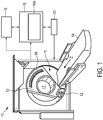
- Fig. 1 shows schematically and exemplarily an embodiment of an X-ray apparatus 10 for grating based phase contrast computed tomography.
- the X-ray apparatus 10 comprises a source-detector arrangement 11 with an X-ray source 12 for emittance of an X-ray beam of coherent or quasi-coherent radiation in a line pattern and further adapted for rotational movement around a rotation axis relative to an object placed on a table 14.
- an X-ray detection system 16 is located opposite the X-ray source 12, wherein during a radiation procedure an object arranged on the table 14 can be moved along direction z parallel to the rotation axis to locate the object in a space 17 between the X-ray source 12 and the X-ray detection system 16.
- the X-ray detection system 16 is adapted to send data to a data processing unit or computing system 18, which preferably is connected to both the X-ray detection system 16 and the X-ray source 12.
- the computing system 18 may be located in the vicinity of the X-ray apparatus 10. Of course, it could also be located at a different place, such as a different laboratory.
- the X-ray source 12 and the X-ray detection system 16 are arranged on a gantry 13.
- the gantry 13 is adapted for rotational movement about the rotation axis relative to an object placed in the space 17.
- a display device or console 20 is arranged in the vicinity of a table 14 to display information to the person operating the X-ray apparatus 10.
- the display device 20 is movably mounted to allow for an individual adjustment depending on the examination situation.
- the display device 20 may also comprise an interface unit to input information by the user.
- the display device 20 is coupled to the computing system 18, which comprises a reconstruction processor 18a.
- the computing system 18 is coupled to a data repository 19, and both the computing system 18 and the data repository 19 are coupled to the X-ray apparatus 10.
- the X-ray detection system 16 generates image data by exposing an object placed on the table 14 to an X-ray beam emitted by the X-ray source 12, wherein said image data is further processed in the X-ray apparatus 10 and the reconstruction processor 18a.
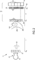
- Fig. 2 shows schematically and exemplarily an embodiment of an X-ray detection system 16 of a source-detector arrangement 11.
- X-ray source 15 comprises an anode 12 and a source grating element 22 (also referred to as G0) to emit an X-ray beam 20 of coherent or quasi-coherent radiation.
- An object 140 is arranged in the path of the X-ray beam 20 between X-ray source 12 and X-ray detection system 16.
- X-ray detection system 16 comprises a first grating element or phase grating element 24 and a second grating element or analyzer grating element 26.
- First grating element 24 can also be referred to as G1
- second grating element 26 can also be referred to as G2.
- First grating element 24 is arranged in a distance 1 from X-ray source 12 with the source grating element 22 and the second grating element 26 is arranged at a distance d from the first grating element.
- Wave front 28a having a uniform phase is depicted as arriving at object 140 while a further phase front 28b having a change phase relationship within the wave front to a phase shift imposed on the wave front while penetrating the object 140 is depicted.
- the second grating element 26 is displaceable 32 relative to the first grating element 24 for acquisition of phase contrast images.
- first grating element 24 is depicted having a uniform pitch p and the second grating element 26 is depicted having a uniform pitch q.
- first grating element 24 is depicted having a uniform pitch p and the second grating element 26 is depicted having a uniform pitch q.
- a detailed illustration regarding exemplary embodiments of the pitch arrangements of both the first and the second grating element may be taken from Figs. 12 or 13 .
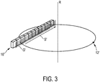
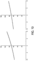
- Fig. 3 shows schematically and exemplarily a conventional setup for grating based differential phase contrast CT with an X-ray source 12' and a detection system 16'.
- the first and second grating elements (for simplicity, Fig. 3 only shows one grating G') are aligned with the rotation axis R and the phase stepping direction S' lies within the plane of rotation.
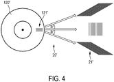
- Such a conventional setup shown in Fig. 3 may conventionally be used, as shown in Fig. 4 , with an anode 120' of an X-ray source having a line pattern 121' for emitting radiation in a line pattern 21'.
- the line pattern 121' of the anode 120' looks like a vertical grating as seen along the optical axis of the arrangement (middle pattern on the right of Fig. 4 ).
- ⁇ ' 15° in this illustration of Fig. 4
- the projection of the line pattern 121' onto a detection system leads to a skewing of the pattern 21' which demands an according tilting of the first and second grating elements of the detection system.
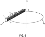
- Fig. 5 shows schematically and exemplarily an embodiment of a setup for a grating based differential phase contrast CT with an X-ray source 12 and a detection system 16 with the first and second grating elements (for simplicity, in Fig. 5 only one grating G is shown) arranged in an orientation orthogonal to the rotation axis R.
- the phase stepping is performed in a phase stepping direction S parallel to the rotation axis R.
- filtered back-projection algorithms may be used to reconstruct the projection of the gradient of the object's real part of refractive index in direction of the rotation axis from the measurement of the gradient of the phase front in direction of the rotation axis by the detection system.
- the use of filtered back-projection algorithms is indicated in particular, when it is sufficient to reconstruct the first derivative of the electron density in the direction of the rotation axis.
- an iterative reconstruction algorithm may be used.
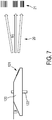
- Figs. 6 and 7 show schematically and exemplarily an embodiment of an anode 120 in top view ( Fig. 6 ) and side view ( Fig. 7 ) for use in an X-ray source 12 according to Fig. 5 .
- Anode 120 is of a rotary type and is arranged on a rotary shaft 122.
- the anode angle ⁇ is again assumed to be 8°, which is however shown for clarity in Fig. 7 significantly enlarged.
- Rotary anode 120 is a structured anode which is adapted to emit an X-ray beam 20 of coherent or quasi-coherent radiation in a line pattern 21.
- Structured rotary anode 120 comprises strips 121 of different radiation emission, which are arranged parallel to the grating lines of the first and/or second gratings as indicated with G in Fig. 5 .
- the X-ray source 12 preferably is provided with a position sensor and a beam deflection unit with an integrated controller as further described with respect to Fig. 8 below.
- the rotary anode 120 may also be unstructured and the line pattern is generated by forming electromagnetically directly the electron beam hitting the anode in a line pattern.
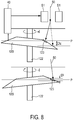
- Fig. 8 shows schematically and exemplarily an embodiment of elements of an X-ray source including a system for measuring and compensating the periodical wobbling of the anode's inclination angle for use with the anode 120 of Fig. 6 and 7 , for example.
- a cross-sectional schematic view of an inclinedly mounted rotary anode 120 on a rotating anode shaft 122 is shown. This usually leads to a periodic position change of a focal spot 123 on the target surface of anode 120 such that the focal spot may be blurred.
- Fig. 8 exemplarily two distinct phases of rotation of rotary anode 120 inclinedly mounted on its rotating anode shaft 122 in a cross-sectional schematic view are shown.
- phase resolved focal spot position for various conditions which may have an influence on the distorting wobble effect (e.g. through anode disk bending due to thermal conditions). Based upon this measurement, control data which are derived from the measurement results of the position sensor 40 are supplied to an integrated beam deflection unit 51 which is used to accordingly steer the electron beam 50 emitted by a cathode of the X-ray source.
- the rotary anode 120 is rotated by 180° in + ⁇ or - ⁇ direction the position of the focal spot 123 is deviated by a deviation amplitude ⁇ z in the direction of the anode shaft's rotational axis.
- the electron beam 50 is steered such that the position of the focal spot 123 stays within the plane P of the center radiation fan beam. Without such a correction of the direction of electron beam 50, if ⁇ z reaches a significant fraction of the projected focal spot diameter ⁇ l, and if the X-ray pulse length is in the order of half the anode rotation period or longer, the X-ray image may be blurred.
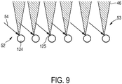
- FIG. 9 shows schematically and exemplarily an embodiment of the provision of liquid metal jets in an X-ray source for use in a setup of Fig. 5 , for example.
- An electron beam structure 52 comprises a plurality 53 of individual electron beams 54 supplied as sub-electron beams.
- the pattern 46 indicates the generated radiation.
- the individual electron beams 54 are supplied to a plurality of liquid metal jets 124. These liquid metal jets 124 provide a plurality of focal lines 125 and form an anode structure resulting in a plurality of X-ray beams 46 to be used as an X-ray source.
- Fig. 10 shows schematically and exemplarily an energy dependence in keV on the vertical axis from the cone angle, which is translated into a dependence on the distance from the central plane, i.e., a dependence on the systems coverage, in mm on the horizontal axis.
- a dependence on the distance from the central plane i.e., a dependence on the systems coverage
- Fig. 10 an example system geometry with an anode angle of 8° (left) or 12° (right), a distance between the X-ray source and the rotation axis of 570 mm and a design energy at 0° cone-angle of 70 keV has been assumed.
- Fig. 10 shows schematically and exemplarily an energy dependence in keV on the vertical axis from the cone angle, which is translated into a dependence on the distance from the central plane, i.e., a dependence on the systems coverage, in mm on the horizontal axis.
- the variation of the grating pitch leads to a variation of the design energy from approximately 55 to 91 keV for a system with 20 mm coverage and an anode angle of 8°. Further, this variation depends strongly on the anode angle as can been seen from a comparison of the right and left part of Fig. 10 , where the variation is reduced to a range of 60 to 83 keV by increasing the anode angle to 12°.
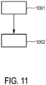
- Fig. 11 shows schematically and exemplarily an embodiment of method for generating and detecting an X-ray beam with a source-detector arrangement of an X-ray apparatus for grating based phase contrast computed tomography with the step 1001 of rotating an X-ray source emitting an X-ray beam of coherent or quasi-coherent radiation relative to an object around a rotation axis and the step 1002 of detecting the radiation by an X-ray detection system including a first grating element and a second grating element and a detector element, wherein the line pattern of the radiation and a grating direction of the grating elements are arranged orthogonal to the rotation axis; and wherein the first grating element has a first grating pitch varied dependent on a cone angle of the X-ray beam and the second grating element has a second grating pitch varied dependent on the cone angle of the X-ray beam.
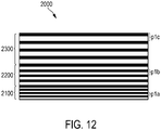
- Fig. 12 shows schematically and exemplarily a first embodiment of a grating element 2000 of an X-ray detection system, which may be employed as a first and/or second grating element, with a grating pitch which is varied gradually or stepwise along the cone angle of the X-ray beam.
- the grating element 2000 shown in Fig. 12 has three different grating pitch sections 2100, 2200, 2300 with the same grating pitch within each one of the sections but with different grating pitches in different grating pitch sections.
- the grating pitch p 1a of grating pitch section 2100 is the same within grating pitch section 2100
- the grating pitch p 1b of grating pitch section 2200 is the same within grating pitch section 2200
- the grating pitch p 1c of grating pitch section 2300 is the same within grating pitch section 230.
- the gratings pitches p 1a , p 1b , p 1c of the three grating pitch sections 2100, 2200, 2300 are different from one another, in particular, grating pitch p 1c of grating pitch section 2300 is larger than grating pitch p 1b of grating pitch section 2200, which again is larger than grating pitch p 1a of grating pitch section 2100.
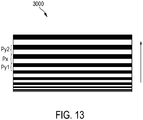
- Fig. 13 shows schematically and exemplarily a second embodiment of a grating element 3000 of an X-ray detection system, which may be employed as a first and/or second grating element, with a grating pitch which is varied uniformly or monotonously along the cone angle of the X-ray beam.
- Each grating line of the grating element 3000 shown in Fig. 13 has a different grating pitch p x compared to adjacent grating lines p y1 , p y2 .
- the grating pitch p x increases with each grating line in a direction indicated with the arrow shown in Fig. 13 .
- a single unit or device may fulfill the functions of several items recited in the claims.
- the mere fact that certain measures are recited in mutually different dependent claims does not indicate that a combination of these measures cannot be used to advantage.
- Operations like control of the source-detector arrangement or the X-ray apparatus in accordance with the method for generating and detecting an X-ray beam or for generating an image of an object, et cetera performed by one or several units or devices can be performed by any other number of units or devices.
- the control of the source-detector arrangement or the X-ray apparatus in accordance with the method for generating and detecting an X-ray beam or for generating an image of an object can be implemented as program code means of a computer program and/or as dedicated hardware.
- a computer program may be stored/distributed on a suitable medium, such as an optical storage medium or a solid-state medium, supplied together with or as part of other hardware, but may also be distributed in other forms, such as via the internet or other wired or wireless telecommunication systems.
- a suitable medium such as an optical storage medium or a solid-state medium, supplied together with or as part of other hardware, but may also be distributed in other forms, such as via the internet or other wired or wireless telecommunication systems.
- the invention relates to a source-detector arrangement of an X-ray apparatus for grating based phase contrast computed tomography.
- the source-detector arrangement comprises an X-ray source adapted for rotational movement around a rotation axis relative to an object and adapted for emittance of an X-ray beam of coherent or quasi-coherent radiation in a line pattern; and an X-ray detection system including a first grating element and a second grating element and a detector element; wherein the line pattern of the radiation and a grating direction of the grating elements are arranged orthogonal to the rotation axis; and wherein the first grating element has a first grating pitch varied dependent on a cone angle of the X-ray beam and/or the second grating element has a second grating pitch varied dependent on the cone angle of the X-ray beam.
Landscapes
- Health & Medical Sciences (AREA)
- Life Sciences & Earth Sciences (AREA)
- Engineering & Computer Science (AREA)
- Medical Informatics (AREA)
- Physics & Mathematics (AREA)
- Optics & Photonics (AREA)
- Heart & Thoracic Surgery (AREA)
- Animal Behavior & Ethology (AREA)
- High Energy & Nuclear Physics (AREA)
- Pathology (AREA)
- Radiology & Medical Imaging (AREA)
- Biomedical Technology (AREA)
- Biophysics (AREA)
- Molecular Biology (AREA)
- Surgery (AREA)
- Nuclear Medicine, Radiotherapy & Molecular Imaging (AREA)
- General Health & Medical Sciences (AREA)
- Public Health (AREA)
- Veterinary Medicine (AREA)
- Pulmonology (AREA)
- Theoretical Computer Science (AREA)
- General Physics & Mathematics (AREA)
- Apparatus For Radiation Diagnosis (AREA)
- Analysing Materials By The Use Of Radiation (AREA)
Applications Claiming Priority (2)
| Application Number | Priority Date | Filing Date | Title |
|---|---|---|---|
| EP14192623 | 2014-11-11 | ||
| PCT/EP2015/076213 WO2016075140A1 (en) | 2014-11-11 | 2015-11-10 | Source-detector arrangement |
Publications (2)
| Publication Number | Publication Date |
|---|---|
| EP3217879A1 EP3217879A1 (en) | 2017-09-20 |
| EP3217879B1 true EP3217879B1 (en) | 2020-01-08 |
Family
ID=51945717
Family Applications (1)
| Application Number | Title | Priority Date | Filing Date |
|---|---|---|---|
| EP15791642.0A Active EP3217879B1 (en) | 2014-11-11 | 2015-11-10 | Source-detector arrangement |
Country Status (5)
| Country | Link |
|---|---|
| US (1) | US10485492B2 (https=) |
| EP (1) | EP3217879B1 (https=) |
| JP (1) | JP7171190B2 (https=) |
| CN (1) | CN106999125B (https=) |
| WO (1) | WO2016075140A1 (https=) |
Families Citing this family (38)
| Publication number | Priority date | Publication date | Assignee | Title |
|---|---|---|---|---|
| US10357222B2 (en) * | 2014-12-26 | 2019-07-23 | Hitachi, Ltd. | X-ray diagnostic imaging apparatus, monitoring server and anomaly detection method |
| US9561206B2 (en) * | 2015-01-07 | 2017-02-07 | The United States Of America, As Represented By The Secretary Of The Navy | Use of heptadecanoic acid (C17:0) to detect risk of and treat hyperferritinemia and metabolic syndrome |
| HK1256971A1 (zh) | 2015-09-28 | 2019-10-04 | 博莱佳私人有限公司 | 空间分析测量系统和方法 |
| US10835193B2 (en) * | 2016-09-08 | 2020-11-17 | Koninklijke Philips N.V. | Source grating for X-ray imaging |
| DE102016217509A1 (de) * | 2016-09-14 | 2018-03-15 | Siemens Healthcare Gmbh | Verfahren und Röntgenvorrichtung zur Erzeugung einer projektiven Röntgendarstellung eines Untersuchungsobjektes |
| CA3044075A1 (en) * | 2016-11-16 | 2018-05-24 | Baraja Pty Ltd | An optical beam director |
| US11039807B2 (en) * | 2016-12-19 | 2021-06-22 | Koninklijke Philips N.V. | System and method for dark-field-imaging |
| US10872708B2 (en) * | 2017-07-24 | 2020-12-22 | Board Of Supervisors Of Louisiana State University And Agricultural And Mechanical College | Phase contrast X-ray interferometry |
| EP3446630A1 (en) | 2017-08-23 | 2019-02-27 | Koninklijke Philips N.V. | Device and method for phase stepping in phase contrast image acquisition |
| KR102701244B1 (ko) | 2017-10-23 | 2024-09-02 | 에피트래커, 인코포레이티드 | 지방산 유사체 및 대사 증후군 관련 병태 치료에서의 그의 용도 |
| EP3502674A1 (en) * | 2017-12-19 | 2019-06-26 | Koninklijke Philips N.V. | Testing of curved x-ray gratings |
| CN110868932B (zh) * | 2017-12-25 | 2024-02-09 | 株式会社岛津制作所 | 放射线相位差摄影装置 |
| AU2019274431B2 (en) | 2018-05-23 | 2025-03-13 | Epitracker, Inc. | Compositions and methods for diagnosis and treatment of conditions related to the quality of aging and longevity |
| US10845491B2 (en) | 2018-06-04 | 2020-11-24 | Sigray, Inc. | Energy-resolving x-ray detection system |
| GB2591630B (en) | 2018-07-26 | 2023-05-24 | Sigray Inc | High brightness x-ray reflection source |
| DE112019004478T5 (de) | 2018-09-07 | 2021-07-08 | Sigray, Inc. | System und verfahren zur röntgenanalyse mit wählbarer tiefe |
| TWI682160B (zh) * | 2018-12-11 | 2020-01-11 | 國立交通大學 | 生物訊號分析元件、生物感測裝置、感測方法以及生物訊號分析元件的製作方法 |
| EP3908374A4 (en) | 2019-01-09 | 2022-12-28 | Epitracker, Inc. | COMPOSITIONS AND METHODS FOR DIAGNOSIS AND TREATMENT OF NEURODEGENERATIVE DISEASES |
| JP7404382B2 (ja) | 2019-03-04 | 2023-12-25 | エピトラッカー インコーポレイテッド | 脂肪酸アナログ、ならびに認知機能障害、行動症状および慢性疼痛の処置におけるそれらの使用 |
| US11143605B2 (en) | 2019-09-03 | 2021-10-12 | Sigray, Inc. | System and method for computed laminography x-ray fluorescence imaging |
| CN110664420B (zh) * | 2019-10-11 | 2023-04-07 | 上海联影医疗科技股份有限公司 | 焦点校正方法、装置、计算机设备和计算机可读存储介质 |
| JP7705852B2 (ja) * | 2019-10-24 | 2025-07-10 | ノヴァ メジャリング インスツルメンツ インコーポレイテッド | パターン化x線放出ターゲット |
| US11175243B1 (en) | 2020-02-06 | 2021-11-16 | Sigray, Inc. | X-ray dark-field in-line inspection for semiconductor samples |
| CN115667896B (zh) | 2020-05-18 | 2024-06-21 | 斯格瑞公司 | 使用晶体分析器和多个检测元件的x射线吸收光谱的系统和方法 |
| EP3925539A1 (en) | 2020-06-19 | 2021-12-22 | Koninklijke Philips N.V. | X-ray imaging system |
| JP7640682B2 (ja) | 2020-09-17 | 2025-03-05 | シグレイ、インコーポレイテッド | X線を用いた深さ分解計測および分析のためのシステムおよび方法 |
| US12480892B2 (en) | 2020-12-07 | 2025-11-25 | Sigray, Inc. | High throughput 3D x-ray imaging system using a transmission x-ray source |
| KR102927910B1 (ko) | 2020-12-07 | 2026-02-19 | 시그레이, 아이엔씨. | 투과 x-선 소스를 이용한 고처리량 3D x-선 이미징 시스템 |
| EP4426130A1 (en) | 2021-11-03 | 2024-09-11 | Epitracker, Inc. | Pentadecanoylcarnitine for treatment of conditions related to the quality of aging and longevity |
| US12360067B2 (en) | 2022-03-02 | 2025-07-15 | Sigray, Inc. | X-ray fluorescence system and x-ray source with electrically insulative target material |
| DE112023001408T5 (de) | 2022-03-15 | 2025-02-13 | Sigray, Inc. | System und verfahren für die kompakte laminographie unter verwendung einer mikrofokus-transmissionsröntgenquelle und eines röntgendetektors mit variabler vergrösserung |
| DE112023002079T5 (de) | 2022-05-02 | 2025-02-27 | Sigray, Inc. | Sequenzielles wellenlängendispersives röntgenspektrometer |
| WO2024173256A1 (en) | 2023-02-16 | 2024-08-22 | Sigray, Inc. | X-ray detector system with at least two stacked flat bragg diffractors |
| US12181423B1 (en) | 2023-09-07 | 2024-12-31 | Sigray, Inc. | Secondary image removal using high resolution x-ray transmission sources |
| WO2025101530A1 (en) | 2023-11-07 | 2025-05-15 | Sigray, Inc. | System and method for x-ray absorption spectroscopy using spectral information from two orthogonal planes |
| WO2025151383A1 (en) | 2024-01-08 | 2025-07-17 | Sigray, Inc. | X-ray analysis system with focused x-ray beam and non-x-ray microscope |
| WO2025155719A1 (en) | 2024-01-18 | 2025-07-24 | Sigray, Inc. | Sequential array of x-ray imaging detectors |
| WO2025174966A1 (en) | 2024-02-15 | 2025-08-21 | Sigray, Inc. | System and method for generating a focused x‑ray beam |
Family Cites Families (23)
| Publication number | Priority date | Publication date | Assignee | Title |
|---|---|---|---|---|
| DE10127269B4 (de) * | 2001-06-05 | 2015-09-24 | Siemens Aktiengesellschaft | Verfahren für die Computertomographie sowie Computertomographie (CT)-Gerät |
| WO2007074029A1 (de) | 2005-12-27 | 2007-07-05 | Siemens Aktiengesellschaft | Fokus- detektor- anordnung zur erzeugung von phasenkontrast-röntgenaufnahmen und verfahren hierzu |
| DE102006037256B4 (de) | 2006-02-01 | 2017-03-30 | Paul Scherer Institut | Fokus-Detektor-Anordnung einer Röntgenapparatur zur Erzeugung projektiver oder tomographischer Phasenkontrastaufnahmen sowie Röntgensystem, Röntgen-C-Bogen-System und Röntgen-CT-System |
| DE102006063048B3 (de) | 2006-02-01 | 2018-03-29 | Siemens Healthcare Gmbh | Fokus/Detektor-System einer Röntgenapparatur zur Erzeugung von Phasenkontrastaufnahmen |
| DE102006037254B4 (de) * | 2006-02-01 | 2017-08-03 | Paul Scherer Institut | Fokus-Detektor-Anordnung zur Erzeugung projektiver oder tomographischer Phasenkontrastaufnahmen mit röntgenoptischen Gittern, sowie Röntgen-System, Röntgen-C-Bogen-System und Röntgen-Computer-Tomographie-System |
| JP2009133823A (ja) | 2007-10-31 | 2009-06-18 | Fujifilm Corp | 放射線画像検出器および放射線位相画像撮影装置 |
| EP2073040A2 (en) * | 2007-10-31 | 2009-06-24 | FUJIFILM Corporation | Radiation image detector and phase contrast radiation imaging apparatus |
| JP5461438B2 (ja) * | 2008-02-14 | 2014-04-02 | コーニンクレッカ フィリップス エヌ ヴェ | 位相コントラストイメージング用のx線検出器 |
| US8401144B2 (en) * | 2008-08-07 | 2013-03-19 | Koninklijke Philips Electronics N.V. | Method and apparatus for correcting artifacts in circular CT scans |
| DE102008048688B4 (de) * | 2008-09-24 | 2011-08-25 | Paul Scherrer Institut | Röntgen-CT-System zur Erzeugung tomographischer Phasenkontrast- oder Dunkelfeldaufnahmen |
| CN101413905B (zh) * | 2008-10-10 | 2011-03-16 | 深圳大学 | X射线微分干涉相衬成像系统 |
| RU2529497C2 (ru) * | 2008-12-08 | 2014-09-27 | Конинклейке Филипс Электроникс Н.В. | Компенсация колебаний анода в рентгеновских трубках с вращающимся анодом |
| DE102009004702B4 (de) * | 2009-01-15 | 2019-01-31 | Paul Scherer Institut | Anordnung und Verfahren zur projektiven und/oder tomographischen Phasenkontrastbildgebung mit Röntgenstrahlung |
| US7949095B2 (en) * | 2009-03-02 | 2011-05-24 | University Of Rochester | Methods and apparatus for differential phase-contrast fan beam CT, cone-beam CT and hybrid cone-beam CT |
| WO2010150136A1 (en) | 2009-06-22 | 2010-12-29 | Koninklijke Philips Electronics N. V. | Grating-based phase contrast x-ray imaging apparatus and methods |
| CN102651998B (zh) | 2009-12-10 | 2015-08-05 | 皇家飞利浦电子股份有限公司 | 用于微分相衬成像的扫描系统 |
| US9031201B2 (en) | 2010-07-05 | 2015-05-12 | Canon Kabushiki Kaisha | X-ray source, X-ray imaging apparatus, and X-ray computed tomography imaging system |
| JP2012143553A (ja) | 2010-12-24 | 2012-08-02 | Fujifilm Corp | 放射線画像撮影装置および放射線画像検出器 |
| JP5804843B2 (ja) * | 2011-08-22 | 2015-11-04 | キヤノン株式会社 | X線撮像装置 |
| US9001967B2 (en) | 2012-12-28 | 2015-04-07 | Carestream Health, Inc. | Spectral grating-based differential phase contrast system for medical radiographic imaging |
| EP2956954B1 (en) | 2013-02-13 | 2017-03-15 | Koninklijke Philips N.V. | Multiple x-ray beam tube |
| EP2978377B1 (en) | 2013-03-26 | 2021-05-05 | Institute of Experimental and Applied Physics | Method of phase gradient radiography and arrangement of an imaging system for application of the method |
| DE102013214393A1 (de) * | 2013-07-23 | 2014-11-20 | Siemens Aktiengesellschaft | Röntgenaufnahmesystem zur differentiellen Phasenkontrast-Bildgebung eines Untersuchungsobjekts mit Phase-Stepping |
-
2015
- 2015-11-10 JP JP2017523461A patent/JP7171190B2/ja active Active
- 2015-11-10 EP EP15791642.0A patent/EP3217879B1/en active Active
- 2015-11-10 WO PCT/EP2015/076213 patent/WO2016075140A1/en not_active Ceased
- 2015-11-10 CN CN201580060997.2A patent/CN106999125B/zh active Active
- 2015-11-10 US US15/524,112 patent/US10485492B2/en active Active
Non-Patent Citations (1)
| Title |
|---|
| None * |
Also Published As
| Publication number | Publication date |
|---|---|
| WO2016075140A1 (en) | 2016-05-19 |
| US10485492B2 (en) | 2019-11-26 |
| CN106999125A (zh) | 2017-08-01 |
| EP3217879A1 (en) | 2017-09-20 |
| CN106999125B (zh) | 2021-02-02 |
| JP2017536879A (ja) | 2017-12-14 |
| US20170319149A1 (en) | 2017-11-09 |
| JP7171190B2 (ja) | 2022-11-15 |
Similar Documents
| Publication | Publication Date | Title |
|---|---|---|
| EP3217879B1 (en) | Source-detector arrangement | |
| KR101318221B1 (ko) | X선 촬상장치 및 x선 촬상방법 | |
| JP5789613B2 (ja) | オンザフライ位相ステッピングを備えた非平行な格子装置、x線システム及び使用方法 | |
| EP3687403B1 (en) | X-ray imaging reference scan | |
| EP2611364B1 (en) | Differential phase-contrast imaging with improved sampling | |
| EP2509503B1 (en) | Apparatus for phase-contrast imaging comprising a displaceable x-ray detector element and method | |
| EP3307167B1 (en) | Tiled detector arrangement for differential phase contrast ct | |
| JP5127249B2 (ja) | X線装置の焦点‐検出器装置のx線光学透過格子 | |
| JP5896999B2 (ja) | X線装置 | |
| CN102781327B (zh) | 相衬成像 | |
| CN101011250B (zh) | X射线设备的用于产生相位对比照片的焦点-检测器装置 | |
| JP5815197B2 (ja) | 多色性分布を持つx線ビームを用いて対象物の画像を検知するシステムと方法 | |
| US10420521B2 (en) | Grating device for an X-ray imaging device | |
| JP6789591B2 (ja) | 放射線位相撮像装置 | |
| KR102426991B1 (ko) | 방사선 화상 생성 장치 | |
| Safca et al. | Perspective on using talbot-lau x-ray phase contrast imaging for atherosclerosis diagnosis | |
| JP5733908B2 (ja) | X線撮像装置 | |
| JP2006071472A (ja) | Ct法およびct装置 | |
| Viermetz et al. | Dark-Field for Human CT–Realization of a Talbot-Lau Interferometer in a Clinical CT Gantry |
Legal Events
| Date | Code | Title | Description |
|---|---|---|---|
| STAA | Information on the status of an ep patent application or granted ep patent |
Free format text: STATUS: THE INTERNATIONAL PUBLICATION HAS BEEN MADE |
|
| PUAI | Public reference made under article 153(3) epc to a published international application that has entered the european phase |
Free format text: ORIGINAL CODE: 0009012 |
|
| STAA | Information on the status of an ep patent application or granted ep patent |
Free format text: STATUS: REQUEST FOR EXAMINATION WAS MADE |
|
| 17P | Request for examination filed |
Effective date: 20170612 |
|
| AK | Designated contracting states |
Kind code of ref document: A1 Designated state(s): AL AT BE BG CH CY CZ DE DK EE ES FI FR GB GR HR HU IE IS IT LI LT LU LV MC MK MT NL NO PL PT RO RS SE SI SK SM TR |
|
| AX | Request for extension of the european patent |
Extension state: BA ME |
|
| DAV | Request for validation of the european patent (deleted) | ||
| DAX | Request for extension of the european patent (deleted) | ||
| GRAP | Despatch of communication of intention to grant a patent |
Free format text: ORIGINAL CODE: EPIDOSNIGR1 |
|
| STAA | Information on the status of an ep patent application or granted ep patent |
Free format text: STATUS: GRANT OF PATENT IS INTENDED |
|
| INTG | Intention to grant announced |
Effective date: 20190603 |
|
| GRAS | Grant fee paid |
Free format text: ORIGINAL CODE: EPIDOSNIGR3 |
|
| GRAA | (expected) grant |
Free format text: ORIGINAL CODE: 0009210 |
|
| STAA | Information on the status of an ep patent application or granted ep patent |
Free format text: STATUS: THE PATENT HAS BEEN GRANTED |
|
| AK | Designated contracting states |
Kind code of ref document: B1 Designated state(s): AL AT BE BG CH CY CZ DE DK EE ES FI FR GB GR HR HU IE IS IT LI LT LU LV MC MK MT NL NO PL PT RO RS SE SI SK SM TR |
|
| REG | Reference to a national code |
Ref country code: GB Ref legal event code: FG4D |
|
| REG | Reference to a national code |
Ref country code: CH Ref legal event code: EP |
|
| REG | Reference to a national code |
Ref country code: DE Ref legal event code: R096 Ref document number: 602015045239 Country of ref document: DE |
|
| REG | Reference to a national code |
Ref country code: IE Ref legal event code: FG4D |
|
| REG | Reference to a national code |
Ref country code: AT Ref legal event code: REF Ref document number: 1221661 Country of ref document: AT Kind code of ref document: T Effective date: 20200215 |
|
| RAP2 | Party data changed (patent owner data changed or rights of a patent transferred) |
Owner name: KONINKLIJKE PHILIPS N.V. |
|
| REG | Reference to a national code |
Ref country code: DE Ref legal event code: R084 Ref document number: 602015045239 Country of ref document: DE |
|
| REG | Reference to a national code |
Ref country code: NL Ref legal event code: MP Effective date: 20200108 |
|
| REG | Reference to a national code |
Ref country code: LT Ref legal event code: MG4D |
|
| PG25 | Lapsed in a contracting state [announced via postgrant information from national office to epo] |
Ref country code: PT Free format text: LAPSE BECAUSE OF FAILURE TO SUBMIT A TRANSLATION OF THE DESCRIPTION OR TO PAY THE FEE WITHIN THE PRESCRIBED TIME-LIMIT Effective date: 20200531 Ref country code: FI Free format text: LAPSE BECAUSE OF FAILURE TO SUBMIT A TRANSLATION OF THE DESCRIPTION OR TO PAY THE FEE WITHIN THE PRESCRIBED TIME-LIMIT Effective date: 20200108 Ref country code: NO Free format text: LAPSE BECAUSE OF FAILURE TO SUBMIT A TRANSLATION OF THE DESCRIPTION OR TO PAY THE FEE WITHIN THE PRESCRIBED TIME-LIMIT Effective date: 20200408 Ref country code: LT Free format text: LAPSE BECAUSE OF FAILURE TO SUBMIT A TRANSLATION OF THE DESCRIPTION OR TO PAY THE FEE WITHIN THE PRESCRIBED TIME-LIMIT Effective date: 20200108 Ref country code: RS Free format text: LAPSE BECAUSE OF FAILURE TO SUBMIT A TRANSLATION OF THE DESCRIPTION OR TO PAY THE FEE WITHIN THE PRESCRIBED TIME-LIMIT Effective date: 20200108 Ref country code: NL Free format text: LAPSE BECAUSE OF FAILURE TO SUBMIT A TRANSLATION OF THE DESCRIPTION OR TO PAY THE FEE WITHIN THE PRESCRIBED TIME-LIMIT Effective date: 20200108 |
|
| PG25 | Lapsed in a contracting state [announced via postgrant information from national office to epo] |
Ref country code: BG Free format text: LAPSE BECAUSE OF FAILURE TO SUBMIT A TRANSLATION OF THE DESCRIPTION OR TO PAY THE FEE WITHIN THE PRESCRIBED TIME-LIMIT Effective date: 20200408 Ref country code: GR Free format text: LAPSE BECAUSE OF FAILURE TO SUBMIT A TRANSLATION OF THE DESCRIPTION OR TO PAY THE FEE WITHIN THE PRESCRIBED TIME-LIMIT Effective date: 20200409 Ref country code: IS Free format text: LAPSE BECAUSE OF FAILURE TO SUBMIT A TRANSLATION OF THE DESCRIPTION OR TO PAY THE FEE WITHIN THE PRESCRIBED TIME-LIMIT Effective date: 20200508 Ref country code: SE Free format text: LAPSE BECAUSE OF FAILURE TO SUBMIT A TRANSLATION OF THE DESCRIPTION OR TO PAY THE FEE WITHIN THE PRESCRIBED TIME-LIMIT Effective date: 20200108 Ref country code: LV Free format text: LAPSE BECAUSE OF FAILURE TO SUBMIT A TRANSLATION OF THE DESCRIPTION OR TO PAY THE FEE WITHIN THE PRESCRIBED TIME-LIMIT Effective date: 20200108 Ref country code: HR Free format text: LAPSE BECAUSE OF FAILURE TO SUBMIT A TRANSLATION OF THE DESCRIPTION OR TO PAY THE FEE WITHIN THE PRESCRIBED TIME-LIMIT Effective date: 20200108 |
|
| REG | Reference to a national code |
Ref country code: DE Ref legal event code: R097 Ref document number: 602015045239 Country of ref document: DE |
|
| PG25 | Lapsed in a contracting state [announced via postgrant information from national office to epo] |
Ref country code: DK Free format text: LAPSE BECAUSE OF FAILURE TO SUBMIT A TRANSLATION OF THE DESCRIPTION OR TO PAY THE FEE WITHIN THE PRESCRIBED TIME-LIMIT Effective date: 20200108 Ref country code: ES Free format text: LAPSE BECAUSE OF FAILURE TO SUBMIT A TRANSLATION OF THE DESCRIPTION OR TO PAY THE FEE WITHIN THE PRESCRIBED TIME-LIMIT Effective date: 20200108 Ref country code: SK Free format text: LAPSE BECAUSE OF FAILURE TO SUBMIT A TRANSLATION OF THE DESCRIPTION OR TO PAY THE FEE WITHIN THE PRESCRIBED TIME-LIMIT Effective date: 20200108 Ref country code: CZ Free format text: LAPSE BECAUSE OF FAILURE TO SUBMIT A TRANSLATION OF THE DESCRIPTION OR TO PAY THE FEE WITHIN THE PRESCRIBED TIME-LIMIT Effective date: 20200108 Ref country code: RO Free format text: LAPSE BECAUSE OF FAILURE TO SUBMIT A TRANSLATION OF THE DESCRIPTION OR TO PAY THE FEE WITHIN THE PRESCRIBED TIME-LIMIT Effective date: 20200108 Ref country code: EE Free format text: LAPSE BECAUSE OF FAILURE TO SUBMIT A TRANSLATION OF THE DESCRIPTION OR TO PAY THE FEE WITHIN THE PRESCRIBED TIME-LIMIT Effective date: 20200108 Ref country code: SM Free format text: LAPSE BECAUSE OF FAILURE TO SUBMIT A TRANSLATION OF THE DESCRIPTION OR TO PAY THE FEE WITHIN THE PRESCRIBED TIME-LIMIT Effective date: 20200108 |
|
| PLBE | No opposition filed within time limit |
Free format text: ORIGINAL CODE: 0009261 |
|
| STAA | Information on the status of an ep patent application or granted ep patent |
Free format text: STATUS: NO OPPOSITION FILED WITHIN TIME LIMIT |
|
| REG | Reference to a national code |
Ref country code: AT Ref legal event code: MK05 Ref document number: 1221661 Country of ref document: AT Kind code of ref document: T Effective date: 20200108 |
|
| 26N | No opposition filed |
Effective date: 20201009 |
|
| PG25 | Lapsed in a contracting state [announced via postgrant information from national office to epo] |
Ref country code: IT Free format text: LAPSE BECAUSE OF FAILURE TO SUBMIT A TRANSLATION OF THE DESCRIPTION OR TO PAY THE FEE WITHIN THE PRESCRIBED TIME-LIMIT Effective date: 20200108 Ref country code: AT Free format text: LAPSE BECAUSE OF FAILURE TO SUBMIT A TRANSLATION OF THE DESCRIPTION OR TO PAY THE FEE WITHIN THE PRESCRIBED TIME-LIMIT Effective date: 20200108 |
|
| PG25 | Lapsed in a contracting state [announced via postgrant information from national office to epo] |
Ref country code: SI Free format text: LAPSE BECAUSE OF FAILURE TO SUBMIT A TRANSLATION OF THE DESCRIPTION OR TO PAY THE FEE WITHIN THE PRESCRIBED TIME-LIMIT Effective date: 20200108 Ref country code: PL Free format text: LAPSE BECAUSE OF FAILURE TO SUBMIT A TRANSLATION OF THE DESCRIPTION OR TO PAY THE FEE WITHIN THE PRESCRIBED TIME-LIMIT Effective date: 20200108 |
|
| PG25 | Lapsed in a contracting state [announced via postgrant information from national office to epo] |
Ref country code: MC Free format text: LAPSE BECAUSE OF FAILURE TO SUBMIT A TRANSLATION OF THE DESCRIPTION OR TO PAY THE FEE WITHIN THE PRESCRIBED TIME-LIMIT Effective date: 20200108 |
|
| REG | Reference to a national code |
Ref country code: CH Ref legal event code: PL |
|
| GBPC | Gb: european patent ceased through non-payment of renewal fee |
Effective date: 20201110 |
|
| PG25 | Lapsed in a contracting state [announced via postgrant information from national office to epo] |
Ref country code: LU Free format text: LAPSE BECAUSE OF NON-PAYMENT OF DUE FEES Effective date: 20201110 |
|
| REG | Reference to a national code |
Ref country code: BE Ref legal event code: MM Effective date: 20201130 |
|
| PG25 | Lapsed in a contracting state [announced via postgrant information from national office to epo] |
Ref country code: LI Free format text: LAPSE BECAUSE OF NON-PAYMENT OF DUE FEES Effective date: 20201130 Ref country code: CH Free format text: LAPSE BECAUSE OF NON-PAYMENT OF DUE FEES Effective date: 20201130 |
|
| PG25 | Lapsed in a contracting state [announced via postgrant information from national office to epo] |
Ref country code: IE Free format text: LAPSE BECAUSE OF NON-PAYMENT OF DUE FEES Effective date: 20201110 |
|
| PG25 | Lapsed in a contracting state [announced via postgrant information from national office to epo] |
Ref country code: GB Free format text: LAPSE BECAUSE OF NON-PAYMENT OF DUE FEES Effective date: 20201110 |
|
| PG25 | Lapsed in a contracting state [announced via postgrant information from national office to epo] |
Ref country code: TR Free format text: LAPSE BECAUSE OF FAILURE TO SUBMIT A TRANSLATION OF THE DESCRIPTION OR TO PAY THE FEE WITHIN THE PRESCRIBED TIME-LIMIT Effective date: 20200108 Ref country code: MT Free format text: LAPSE BECAUSE OF FAILURE TO SUBMIT A TRANSLATION OF THE DESCRIPTION OR TO PAY THE FEE WITHIN THE PRESCRIBED TIME-LIMIT Effective date: 20200108 Ref country code: CY Free format text: LAPSE BECAUSE OF FAILURE TO SUBMIT A TRANSLATION OF THE DESCRIPTION OR TO PAY THE FEE WITHIN THE PRESCRIBED TIME-LIMIT Effective date: 20200108 |
|
| PG25 | Lapsed in a contracting state [announced via postgrant information from national office to epo] |
Ref country code: MK Free format text: LAPSE BECAUSE OF FAILURE TO SUBMIT A TRANSLATION OF THE DESCRIPTION OR TO PAY THE FEE WITHIN THE PRESCRIBED TIME-LIMIT Effective date: 20200108 Ref country code: AL Free format text: LAPSE BECAUSE OF FAILURE TO SUBMIT A TRANSLATION OF THE DESCRIPTION OR TO PAY THE FEE WITHIN THE PRESCRIBED TIME-LIMIT Effective date: 20200108 |
|
| PG25 | Lapsed in a contracting state [announced via postgrant information from national office to epo] |
Ref country code: BE Free format text: LAPSE BECAUSE OF NON-PAYMENT OF DUE FEES Effective date: 20201130 |
|
| PGFP | Annual fee paid to national office [announced via postgrant information from national office to epo] |
Ref country code: DE Payment date: 20251126 Year of fee payment: 11 |
|
| PGFP | Annual fee paid to national office [announced via postgrant information from national office to epo] |
Ref country code: FR Payment date: 20251125 Year of fee payment: 11 |