EP3217830B1 - Article chaussant avec ensemble semelle ayant un élément de vessie et un composant guide, et procédé de fabrication de l'article chaussant - Google Patents
Article chaussant avec ensemble semelle ayant un élément de vessie et un composant guide, et procédé de fabrication de l'article chaussant Download PDFInfo
- Publication number
- EP3217830B1 EP3217830B1 EP15771360.3A EP15771360A EP3217830B1 EP 3217830 B1 EP3217830 B1 EP 3217830B1 EP 15771360 A EP15771360 A EP 15771360A EP 3217830 B1 EP3217830 B1 EP 3217830B1
- Authority
- EP
- European Patent Office
- Prior art keywords
- footwear
- article
- guide component
- elongated members
- bladder element
- Prior art date
- Legal status (The legal status is an assumption and is not a legal conclusion. Google has not performed a legal analysis and makes no representation as to the accuracy of the status listed.)
- Active
Links
- 238000004519 manufacturing process Methods 0.000 title description 6
- 238000004873 anchoring Methods 0.000 claims description 32
- 239000000463 material Substances 0.000 claims description 23
- 230000000717 retained effect Effects 0.000 claims description 5
- 238000003856 thermoforming Methods 0.000 description 26
- 210000002683 foot Anatomy 0.000 description 18
- 238000000034 method Methods 0.000 description 17
- 239000012530 fluid Substances 0.000 description 10
- 229920002803 thermoplastic polyurethane Polymers 0.000 description 9
- IJGRMHOSHXDMSA-UHFFFAOYSA-N Atomic nitrogen Chemical compound N#N IJGRMHOSHXDMSA-UHFFFAOYSA-N 0.000 description 8
- 239000004433 Thermoplastic polyurethane Substances 0.000 description 8
- 229920002635 polyurethane Polymers 0.000 description 5
- 239000004814 polyurethane Substances 0.000 description 5
- 230000006835 compression Effects 0.000 description 4
- 238000007906 compression Methods 0.000 description 4
- 239000007789 gas Substances 0.000 description 4
- 229910052757 nitrogen Inorganic materials 0.000 description 4
- 229920000219 Ethylene vinyl alcohol Polymers 0.000 description 3
- 230000004888 barrier function Effects 0.000 description 3
- 239000004744 fabric Substances 0.000 description 3
- 210000000454 fifth toe Anatomy 0.000 description 3
- 210000001255 hallux Anatomy 0.000 description 3
- VGGSQFUCUMXWEO-UHFFFAOYSA-N Ethene Chemical compound C=C VGGSQFUCUMXWEO-UHFFFAOYSA-N 0.000 description 2
- IMROMDMJAWUWLK-UHFFFAOYSA-N Ethenol Chemical compound OC=C IMROMDMJAWUWLK-UHFFFAOYSA-N 0.000 description 2
- 239000005977 Ethylene Substances 0.000 description 2
- 239000004677 Nylon Substances 0.000 description 2
- 230000000386 athletic effect Effects 0.000 description 2
- 229920001577 copolymer Polymers 0.000 description 2
- 210000004744 fore-foot Anatomy 0.000 description 2
- 238000002347 injection Methods 0.000 description 2
- 239000007924 injection Substances 0.000 description 2
- 238000001746 injection moulding Methods 0.000 description 2
- 239000010985 leather Substances 0.000 description 2
- 210000000452 mid-foot Anatomy 0.000 description 2
- 229920001778 nylon Polymers 0.000 description 2
- 229920000728 polyester Polymers 0.000 description 2
- 238000007666 vacuum forming Methods 0.000 description 2
- 239000004721 Polyphenylene oxide Substances 0.000 description 1
- 229920005830 Polyurethane Foam Polymers 0.000 description 1
- 230000000712 assembly Effects 0.000 description 1
- 238000000429 assembly Methods 0.000 description 1
- 238000000071 blow moulding Methods 0.000 description 1
- 238000004891 communication Methods 0.000 description 1
- 239000002178 crystalline material Substances 0.000 description 1
- 230000001419 dependent effect Effects 0.000 description 1
- 238000010586 diagram Methods 0.000 description 1
- 239000013536 elastomeric material Substances 0.000 description 1
- 239000005038 ethylene vinyl acetate Substances 0.000 description 1
- 239000010408 film Substances 0.000 description 1
- 239000006260 foam Substances 0.000 description 1
- 239000006261 foam material Substances 0.000 description 1
- 239000012528 membrane Substances 0.000 description 1
- 239000000203 mixture Substances 0.000 description 1
- 239000002991 molded plastic Substances 0.000 description 1
- 230000002093 peripheral effect Effects 0.000 description 1
- 229920003023 plastic Polymers 0.000 description 1
- 239000004033 plastic Substances 0.000 description 1
- 229920005906 polyester polyol Polymers 0.000 description 1
- 229920000570 polyether Polymers 0.000 description 1
- 229920000642 polymer Polymers 0.000 description 1
- 239000011496 polyurethane foam Substances 0.000 description 1
- 230000003014 reinforcing effect Effects 0.000 description 1
- 239000012858 resilient material Substances 0.000 description 1
- 230000004043 responsiveness Effects 0.000 description 1
- 238000004826 seaming Methods 0.000 description 1
- 230000035939 shock Effects 0.000 description 1
- 239000004753 textile Substances 0.000 description 1
- 229920001169 thermoplastic Polymers 0.000 description 1
- 229920002725 thermoplastic elastomer Polymers 0.000 description 1
- 229920001187 thermosetting polymer Polymers 0.000 description 1
- 239000004416 thermosoftening plastic Substances 0.000 description 1
- 239000010409 thin film Substances 0.000 description 1
- 210000003371 toe Anatomy 0.000 description 1
Images


Classifications
-
- A—HUMAN NECESSITIES
- A43—FOOTWEAR
- A43B—CHARACTERISTIC FEATURES OF FOOTWEAR; PARTS OF FOOTWEAR
- A43B13/00—Soles; Sole-and-heel integral units
- A43B13/14—Soles; Sole-and-heel integral units characterised by the constructive form
- A43B13/18—Resilient soles
- A43B13/20—Pneumatic soles filled with a compressible fluid, e.g. air, gas
-
- A—HUMAN NECESSITIES
- A43—FOOTWEAR
- A43B—CHARACTERISTIC FEATURES OF FOOTWEAR; PARTS OF FOOTWEAR
- A43B23/00—Uppers; Boot legs; Stiffeners; Other single parts of footwear
- A43B23/02—Uppers; Boot legs
- A43B23/0245—Uppers; Boot legs characterised by the constructive form
- A43B23/0265—Uppers; Boot legs characterised by the constructive form having different properties in different directions
-
- A—HUMAN NECESSITIES
- A43—FOOTWEAR
- A43C—FASTENINGS OR ATTACHMENTS OF FOOTWEAR; LACES IN GENERAL
- A43C11/00—Other fastenings specially adapted for shoes
- A43C11/16—Fastenings secured by wire, bolts, or the like
-
- B—PERFORMING OPERATIONS; TRANSPORTING
- B29—WORKING OF PLASTICS; WORKING OF SUBSTANCES IN A PLASTIC STATE IN GENERAL
- B29D—PRODUCING PARTICULAR ARTICLES FROM PLASTICS OR FROM SUBSTANCES IN A PLASTIC STATE
- B29D35/00—Producing footwear
- B29D35/0054—Producing footwear by compression moulding, vulcanising or the like; Apparatus therefor
-
- B—PERFORMING OPERATIONS; TRANSPORTING
- B29—WORKING OF PLASTICS; WORKING OF SUBSTANCES IN A PLASTIC STATE IN GENERAL
- B29D—PRODUCING PARTICULAR ARTICLES FROM PLASTICS OR FROM SUBSTANCES IN A PLASTIC STATE
- B29D35/00—Producing footwear
- B29D35/12—Producing parts thereof, e.g. soles, heels, uppers, by a moulding technique
- B29D35/122—Soles
Definitions
- the present teachings generally include an article of footwear with a sole assembly and a method of manufacturing an article of footwear.
- Footwear typically includes a sole assembly configured to be located under a wearer's foot to space the foot away from the ground or floor surface.
- Sole assemblies can be designed to provide a desired level of cushioning.
- a sole assembly is secured to an upper. The upper often is tightened with a shoelace to secure the article of footwear to a wearer's foot.
- Athletic footwear in particular sometimes utilizes polyurethane foam or other resilient materials in the sole assembly to provide cushioning.
- US 2014/283412 A1 describes an article of footwear including an upper having a first area and a second area, and a sole structure that is coupled to the upper.
- the sole structure includes a bladder that contains a fluid.
- the footwear includes a tensile structure that is coupled to the first area of the upper, that extends through the sole structure, and that is coupled to the second area of the upper.
- the tensile structure is operably coupled to the bladder.
- the tensile structure is operable to flex the bladder due to an increase in tension in the tensile structure.
- An article of footwear includes a sole assembly that has a bladder element with a first outer surface and a second outer surface opposite the first outer surface.
- the sole assembly has a guide component fused to the first outer surface or the second outer surface.
- the guide component has multiple grooves extending laterally across the guide component. The multiple grooves are configured to receive and guide multiple elongated members such that the multiple elongated members are movable lengthwise when positioned within the multiple grooves. In one embodiment, the multiple grooves are three-sided channels.
- the guide component may be formed from a polymeric material in one embodiment.
- the bladder element has side surfaces extending from the first outer surface to the second outer surface, and the guide component has side portions fused to the side surfaces.
- the multiple grooves may include at least two grooves. Adjacent ones of the at least two grooves join with one another on the side portions. Additionally, the guide component may have apertures between adjacent ones of the at least two grooves. The apertures may increase flexibility of the guide component and the bladder element.
- the guide component may have at least one retaining bar that extends across a respective one of the multiple grooves.
- the at least one retaining bar helps to retain the multiple elongated members in the multiple grooves.
- the sole assembly may include an outsole secured to the guide component such that the multiple grooves are partially enclosed by the outsole. Additionally, an upper may be secured to the sole assembly. The upper may have at least one anchoring feature configured to receive the multiple elongated members such that the multiple elongated members extend through the multiple grooves and the at least one anchoring feature, the bladder element thereby being biased toward the upper by force of the multiple elongated members against the guide component.
- the at least one anchoring feature includes an anchoring element secured to a body of the upper at a heel region of the upper.
- the multiple elongated members may extend through an opening in the anchoring element and may be retained between the anchoring element and the body of the upper.
- the at least one anchoring feature includes at least one eyelet in the upper and the multiple elongated members extend through the at least one eyelet.
- the article of footwear may include at least one guide secured to the upper. The multiple elongated members may extend through the at least one guide between the multiple grooves and the at least one eyelet.
- the bladder element has side surfaces that extend from the first outer surface to the second outer surface.
- the guide component has side portions fused to the side surfaces.
- the multiple grooves are at least two grooves. Adjacent ones of the at least two grooves join with one another on the side portions.
- the side portions may include a lateral side portion and a medial side portion.
- the lateral side portion and the medial side portion may each have at least one retaining bar that extends across the multiple grooves to retain the at least one elongated member when the multiple elongated members are positioned in the multiple grooves.
- an article of footwear includes an upper and an outsole.
- a sole assembly is secured to the upper and has a bladder element with a first outer surface facing toward the upper, and a second outer surface opposite the first outer surface facing toward the outsole.
- a lateral side surface and a medial side surface of the bladder element extend from the first outer surface to the second outer surface.
- a guide component is fused to the bladder element.
- the guide component has a bottom portion fused to the second outer surface, a lateral side portion fused to the lateral side surface, and a medial side portion fused to the medial side surface.
- the guide component forms multiple grooves extending laterally across the bottom portion from the lateral side portion to the medial side portion.
- the outsole is secured to the bottom portion of the guide component to enclose the multiple grooves along the bottom portion.
- the upper is configured to be secured to the multiple elongated members so that the multiple elongated members bias the bladder element toward the upper when the multiple elongated members are positioned in the multiple grooves.
- the lateral side portion and the medial side portion of the guide component each have at least one retaining member that extends across the multiple grooves to retain the multiple elongated members when the multiple elongated members are positioned in the multiple grooves.
- the upper has at least one anchoring feature that receives the multiple elongated members such that the multiple elongated members extend through the multiple grooves and through the at least one anchoring feature, the bladder element thereby being biased toward the upper by force of the multiple elongated members against the guide component.
- the at least one anchoring feature may include an anchoring element secured to a body of the upper at a heel region of the upper.
- the multiple elongated members may extend through an opening in the anchoring element and be retained between the anchoring element and the body of the upper.
- the at least one anchoring feature may be at least one eyelet in the upper.
- the at least one elongated member may extend through the at least one eyelet.
- at least one guide may be secured to the upper.
- the multiple elongated members may extend through the at least one guide between the at least one groove and the at least one eyelet.
- a method of manufacturing a sole assembly for an article of footwear includes fusing a guide component to a first outer surface or a second outer surface of a bladder element.
- the second outer surface is opposite the first outer surface.
- the guide component has multiple grooves extending laterally across the guide component. The multiple grooves are configured to receive and guide multiple elongated members such that the multiple elongated members are movable lengthwise when positioned within the multiple grooves.
- the method includes, prior to said fusing the guide component to the first outer surface or the second outer surface of the bladder element, placing the guide component in the thermoforming mold assembly, placing material for the bladder element in the thermoforming mold assembly, and closing the thermoforming mold assembly.
- Placing material for the bladder element in the thermoforming mold assembly may include placing an upper sheet of material for the bladder element and a lower sheet of material for the bladder element in the thermoforming mold assembly after placing the guide component in the thermoforming mold assembly.
- the method may include injection molding the guide component prior to fusing the guide component to the first outer surface or the second outer surface of the bladder element.
- the method may further include securing an outsole to the guide component such that the multiple grooves of the guide component are partially enclosed by the outsole.
- the method may include securing an upper to the bladder element, positioning the multiple elongated members in the multiple grooves, and securing the multiple elongated members to the upper such that the multiple elongated members bias the bladder element toward the upper.
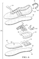
- FIG. 1 shows a fluid-filled bladder element 10 fused to a guide component 12.
- the bladder element 10 and guide component 12 are included in a sole assembly 14 of an article of footwear 16, such as shown in FIG. 5 or an alternative article of footwear 116 shown in FIG. 6 .
- the guide component 12 is configured to receive, retain, and guide multiple elongated members positioned in multiple grooves 36 of the guide component 12 such that the elongated members can be used to bias the bladder element 10 against a wearer's foot in the article of footwear 16.
- the bladder element 10 is pulled upward toward the wearer's foot to minimize relative movement of the bladder element 10 with respect to the foot.
- the article of footwear 16 is an athletic shoe.
- the sole assembly 14 could be for an article of footwear that is a dress shoe, a work shoe, a sandal, a slipper, a boot, or any other category of footwear.
- the bladder element 10 has a first outer surface 18 best shown in FIG. 1 and a second outer surface 20 opposite the first outer surface 18, as best shown in FIGS. 2 and 4 .
- a lateral side surface 22 and a medial side surface 24 each extend from the first outer surface 18 to the second outer surface 20.
- the lateral side surface 22 is best shown in FIG. 2 and may be a mirror image of the medial side surface 24.
- the lateral side surface 22 is positioned on the lateral side of the assembled article of footwear 16 and the medial side surface 24 is positioned on the medial side of the assembled article of footwear 16.
- a lateral side of a component for an article of footwear is a side that corresponds with the side of the foot of the wearer of the article of footwear 16 that is generally further from the other foot of the wearer (i.e., the side closer to the fifth toe of the wearer).
- the fifth toe is commonly referred to as the little toe.
- a medial side of a component for an article of footwear, such as the medial side surface 24 of the bladder element 10 is the side that corresponds with an inside area of the foot of the wearer and is generally closer to the other foot of the wearer (i.e., the side closer to the hallux of the foot of the wearer).
- the hallux is commonly referred to as the big toe.
- a "fluid" retained in the internal cavity of the bladder element 10 may be a gas, such as nitrogen or air.
- a “fluid-filled bladder element” is a bladder element that may be filled with a gas, such as nitrogen or air.
- the bladder element 10 may be thermoformed in a mold assembly 220 (shown in FIGS. 9 and 10 ) from an upper sheet 11 and a lower sheet 13.
- the upper and lower sheets 11, 13 may be vacuum formed to the shape of the mold assembly 220 during the thermoforming process.
- the thermoformed sheets 11, 13 may be bonded to one another at a peripheral flange 15 by compression forming during the thermoforming process to form an internal cavity therebetween.
- a fill tube 17 through which fluid is provided into the internal cavity of the bladder element 10 is shown in FIG. 1 , and is plugged after inflating the bladder element 10 with a fluid such as air or nitrogen.
- the fill tube 17 is subsequently trimmed prior to assembling the article of footwear 16. Accordingly, the fill tube 17 is shown only in FIGS. 1 and 2 .
- Fluid-filled bladder elements can be used to absorb shock and impact forces during use of the article of footwear 16.
- the bladder element 10 is shown positioned in a heel region of the article of footwear 16, the bladder element 10 may instead or in addition be positioned in the midfoot region or the forefoot region, or multiple bladder elements 10 can be positioned in different regions.
- the bladder element 10 can be formed from a variety of polymeric materials that can resiliently retain a fluid such as nitrogen, air, or another gas.
- polymeric materials for the bladder element 10 include thermoplastic urethane, polyurethane, polyester, polyester polyurethane, and polyether polyurethane.
- the bladder element 10 can be formed of layers of different materials including polymeric materials.
- the bladder element 10 is formed from thin films having one or more thermoplastic polyurethane layers with one or more barrier layers of a copolymer of ethylene and vinyl alcohol (EVOH) that is impermeable to the pressurized fluid contained therein as disclosed in U.S. Patent No. 6,082,025 to Bok et al. .
- Bladder element 10 may also be formed from a material that includes alternating layers of thermoplastic polyurethane and ethylene-vinyl alcohol copolymer, as disclosed in U.S. Patent Nos. 5,713,141 and 5,952,065 to Mitchell et al. .
- the layers may include ethylene-vinyl alcohol copolymer, thermoplastic polyurethane, and a regrind material of the ethylene-vinyl alcohol copolymer and thermoplastic polyurethane.
- the bladder element 10 may also be a flexible microlayer membrane that includes alternating layers of a gas barrier material and an elastomeric material, as disclosed in U.S. Patent Nos. 6,082,025 and 6,127,026 to Bonk et al. .
- suitable materials for the bladder element 10 are disclosed in U.S. Patent Nos. 4,183,156 and 4,219,945 to Rudy .
- Further suitable materials for the bladder element 10 include thermoplastic films containing a crystalline material, as disclosed in U.S. Patent Nos. 4,936,029 and 5,042,176 to Rudy , and polyurethane including a polyester polyol, as disclosed in U.S. Patent Nos. 6,013,340 , 6,203,868 , and 6,321,465 to Bonk et al. .
- engineering properties such as tensile strength, stretch properties, fatigue characteristics, dynamic modulus, and loss tangent can be considered.
- the thicknesses of sheets of materials used to form the bladder element 10 can be selected to provide these characteristics.
- the bladder element 10 is resilient and provides cushioning and flexibility that can be tuned such as by selecting a level of pressurization.
- Tensile members and/or reinforcing structures can be integrated with the bladder element 10 to provide desired responsiveness, such as disclosed in U.S. Patent Nos. 4,906,502 to Rudy et al. , and 8,061,060 to Swigart et al. .
- the first outer surface 18 generally faces toward an upper 26 and the opposite second outer surface 20 generally faces toward an outsole 28 in the assembled article of footwear 16.
- Each of the surfaces 18, 20, 22, 24 is generally contoured in the inflated bladder element 10. Accordingly, portions of the first outer surface 18 face in various different directions and portions of the second outer surface 20 face in various different directions. However, the first outer surface 18 is closer than the second outer surface 20 to the upper 26 and at least portions of the first outer surface 18 face toward the upper 26, while at least portions of the second outer surface 20 face toward the outsole 28.
- the bladder element 10 fuses to the guide component 12 during thermoforming of the bladder element 10, as described in FIG. 8 in the method 200 of manufacturing the article of footwear 16, 116.
- the bladder element 10 fuses to the guide component 12 by thermally bonding to the guide component 12 during thermoforming of the bladder element 10.
- the guide component 12 can be any of a wide variety of polymeric materials such as a thermoset or thermoplastic elastomer, nylon, thermoplastic polyurethane, and thermoplastic polyurethane blends, such as thermoplastic polyurethane and nylon.
- the guide component 12 is an injection-molded plastic that is a unitary, one-piece component. Stated differently, the guide component 12 can be a single piece. With reference to FIGS.
- the guide component 12 has a bottom portion 30 fused to the second outer surface 20 of the bladder element 10, a lateral side portion 32 fused to the lateral side surface 22 of the bladder element 10, and a medial side portion 34 fused to the medial side surface 24 of the bladder element 10.
- the guide component 12 has multiple grooves 36 that extend laterally across the bottom portion 30 from the lateral side portion 22 to the medial side portion 24.
- the guide component 12 has multiple grooves 36, and may have at least two grooves 36, as shown.
- the grooves 36 are generally three-sided channels recessed in the guide component 12. Alternatively, the grooves 36 may have a rounded U-shape in cross-section. As formed, except at retaining bars 44 described herein, the grooves 36 are open along their lengths.
- the width W of the grooves 36 is sufficient to allow multiple desired elongated members 40 to be positioned lengthwise in the grooves 36, as shown in FIGS. 3 and 4 , so that the multiple elongated members 40 are movable along their lengths. As shown in FIG.
- FIGS. 3 and 4 show five elongated members 40 that are tensioning cables extending lengthwise through the grooves 36.
- the elongated members 40 can be laces, threads, straps, tethers, cables, or combinations of these.
- FIGS. 2 and 5 show that the guide component 12 has spaced bars 41 separated by apertures 42 in the bottom portion 30 of the guide component 12.
- the grooves 36 are formed in the bars 41.
- the apertures 42 are thus between adjacent ones of the grooves 36.
- the grooves 36 extend continuously from the bottom portion 30 to the side portions 32, 34. Adjacent ones of the grooves 36 merge to join with one another on the side portions 32, 34.
- the lateral side portion 32 and the medial side portion 34 of the guide component 12 are formed with retaining bars 44 each of which extends across a width W of a respective one of the grooves 36 or merged grooves 36.
- Each retaining bar 44 spans across a respective groove 36 (which may be merged grooves 36) to prevent the elongated member 40 from moving out of the open side of the groove 36.
- the upper 26 can be comprised of multiple separate pieces and materials such as fabric, textiles, leather, plastics, etc.
- the upper 26 includes a relatively stiff anchoring element 50 secured to a heel region of the upper 26.
- the upper 26 includes a tongue 54 and various eyelets 52 surround an area in which a tongue 54 resides. Both the anchoring element 50 and the upper 26 at the eyelets 52 serve as anchoring features for the elongated members 40, as discussed herein.
- a shoelace 56 can be laced through the eyelets 52 to tighten the upper 26 across a midportion and forefoot portion of the article of footwear 16.
- the upper 26 may also include one or more leather portions, fabric mesh portions, a toe cap, a cloth lining, and a heel pull strap.
- a strobel unit 58 can be stitched to the upper 26. Alternatively, heat seaming, bonding, or other suitable methods of securing the footwear upper 26 to the strobel unit 58 can be used.
- the strobel unit 58 is also adhered or bonded directly to an upward-facing surface 60 of a midsole layer 62.
- the midsole layer 62 may be formed from a resilient polymer foam material such as polyurethane or ethylene vinyl acetate (EVA).
- EVA ethylene vinyl acetate
- the outsole 28 is bonded to a downward-facing surface 64 of the midsole layer 62.
- the outsole layer 28 can include tread elements 66 that establish a ground contact surface of the article of footwear 16.
- the anchoring element 50 has openings 67 through which a first set of the elongated members 40 are inserted to allow the elongated members 40 to be retained between the anchoring element 50 and the body 69 of the upper 26 around the back of the heel region.
- the ends of each of the first set of elongated members 40 can be knotted, otherwise enlarged, or bonded to the anchoring element 50 after passing through the openings 67 to retain the elongated members 40 to the anchoring element 50.
- the first set of elongated members 40 thus extend through the grooves 36 under the bladder element 10 and to the heel portion of the upper 26 to bias the bladder element 10 generally upward toward the foot 68 of the wearer of the article of footwear 16, as shown in FIG. 3 .
- the elongated members 40 are movable transversely within the grooves 36. That is, the elongated members 40 can move along their lengths (i.e., lengthwise) within the grooves 36 in reaction to forces applied to the article of footwear 16 by impact with the ground or by movement of the wearer's foot 68. Stated differently, the guide component 12 does not restrain movement of the elongated members 40 along their lengths. Allowing relative lengthwise movement of the elongated members 40 with respect to the guide component 12 may further secure the position of the bladder element 10 relative to the foot. Additionally, because the elongated members 40 are biased upward in the grooves 36, they do not touch the outsole 28, which may minimize wear on the elongated members 40.
- the rearmost pair of eyelets 52 also serves as an anchoring feature for a second set of the elongated members 40 that extend through the rearmost eyelets 52.
- One eyelet 52 of the rearmost pair of eyelets 52 is shown in FIG. 3 .
- the other eyelet 52 of the rearmost pair of eyelets 52 is on the opposite side of the upper 26.
- the ends of each of the second set of elongated members 40 can be knotted, otherwise enlarged, or bonded to the upper 26 after passing through the eyelet 52 to retain the elongated members 40 to the upper 26.
- separate looped members can extend downward from the eyelets 52, and the second set of elongated members 40 can form loops that interconnect with the looped members extending downward from the eyelets 52.
- the second set of elongated members 40 thus extend through the grooves 36 under the bladder element 10 and to the midfoot portion of the upper 26 to bias the bladder element 10 generally upward toward the foot 68 of the wearer of the article of footwear 16.
- the second set of elongated members 40 can move along their lengths (i.e., lengthwise) within the grooves 36 in reaction to forces applied to the article of footwear 16 by impact with the ground or by movement of the wearer's foot 68.
- the elongated members 40 can be a single continuous elongated member that is looped through the grooves 36 and the rearmost eyelets 52, and then back through the grooves and through the anchoring component 50 around the back of the upper 26 before its ends are secured to one another or to the upper 26.
- FIG. 6 shows an alternative embodiment of an article of footwear 116 that has many of the same components as the article of footwear 16. Such like components are referred to with the same reference numbers in FIG. 6 as in FIGS. 1-5 , and function as described with respect to FIGS. 1-5 .
- the article of footwear 116 is different from the article of footwear 16 in that the upper 26 includes guides 70 secured to or integrally formed in the sides of the upper 26. Guides 70 on the medial side of the upper 26 are visible in FIG. 6 . Identical guides 70 are included on the lateral side of the upper 26.
- the shoelace 56 serves as an additional elongated member, replacing the second set of elongated members 40 of the article of footwear 16.
- the shoelace 56 extends through the eyelets 52, the guides 70, and at least some of the grooves 36 of the guide component 12. Like the first set of elongated members 40, the shoelace 56 can move along its length (i.e., lengthwise) within the grooves 36 in reaction to forces applied to the article of footwear 10 by impact with the ground or by movement of the wearer's foot.
- the first set of elongated members 40 are positioned through the grooves 36 and through the opening 67 in the anchoring component 50 as described with respect to FIG. 5 .
- FIG. 7 shows an alternative embodiment of an injection molded guide component 112 and the bladder element 10 fused to one another by thermoforming the bladder element 10 with the guide component 112 in a thermoforming mold assembly used to thermoform the bladder element 10.
- the guide component 112 is fused to the first outer surface 18 of the bladder element 10 and is thus positioned between the upper 26 and the bladder element 10 when assembled as part of an article of footwear 16 or 116.
- elongated members When elongated members are positioned in the grooves 36 to extend through the grooves 36, they bias the bladder element 10 upward toward a foot of the wearer of the article of footwear 16, 116 because force on the elongated members acts on the bottom surface 30 of the guide component 112 (i.e., on the underside of the guide component 112 in FIG. 7 , and thus pulls the guide component 112 toward the upper 26. Because the bladder element 10 is fused to the guide component 112, the bladder element 10 is also pulled toward the upper 26.
- FIG. 8 is a flowchart of a method 200 of manufacturing an article of footwear such as the article of footwear 16 of FIG. 5 , or the article of footwear 116 of FIG. 6 .
- the method 200 is described with respect to the article of footwear 16 and the guide component 12, but can also be applied to an article of footwear with the guide component 112 of FIG. 7 .
- the method 200 begins with step 202, injection molding the guide component 12.
- the same entity that performs the step 202 can perform the remaining steps of the method 200.
- different entities can perform different steps of the method 200.
- one entity can injection mold the guide component in step 202, and provide the injection-molded guide component to another entity that performs one or more of the remaining steps of the method 200.
- FIG. 9 shows the thermoforming mold assembly 220 having a first mold 222 and a second mold 224.
- the guide component 12 is shown positioned in the second mold 224 following step 202.
- the first mold 222 has a surface that defines a first mold cavity 223 and generally follows the shape of the first outer surface 18 and portions of the side surfaces 22, 24 of the bladder element 10.
- the second mold 224 has a surface that defines a second mold cavity 225 and generally follows the shape of the second outer surface 20 and portions of the side surfaces 22, 24 of the bladder element 10.
- Each of the mold cavities 223, 225 has a tube portion 227 which creates the fill tube 17 when the sheets 11, 13 are thermoformed.
- the resulting fill tube 17 can be plugged and trimmed.
- the flange portion 15 resulting by compression forming the upper and lower sheets 11, 13 is also trimmed after thermoforming to the resulting flange 15 of FIG. 1 .
- step 206 material for the bladder element 10 is placed in the thermoforming mold assembly 220.
- the bladder element 10 may be formed from the upper sheet 11 and the lower sheet 13.
- Each of the sheets 11, 13 can have multiple layers of thermoplastic polyurethane alternating with one or more barrier layers of a copolymer of ethylene and vinyl alcohol (EVOH), as discussed above.
- Step 206 may occur after step 204 in the embodiment shown.
- the sheets 11, 13 are placed on top of the guide component 12 in the second mold 224.
- step 204 could occur before step 202. If a blow-molding technique is used to form the bladder element 10 instead of the technique using two sheets, then softened material for the bladder element 10 generally in the shape of a tube is placed in the mold 224 instead of the sheets 11, 13.
- the molds 222, 224 are closed together in step 208 by aligning the first mold 222 with the second mold 224 so that the mold cavities 223, 225 align with one another, and the tube portions 227 align with one another.
- the guide component 12 is fused to the bladder element 10, such as by thermoforming the bladder element 10.
- the thermoforming process sufficiently heats the bladder element material (i.e., the sheets 11, 13) and the guide component 12 so that they fuse to one another.
- Fusing the bladder element 10 to the guide component 12 in the mold assembly 220 in step 210 can include vacuum forming the sheets 11, 13 to conform to the molds 222, 224, respectively.
- a vacuum source can be in fluid communication with the cavities 223, 225 of the closed mold assembly 220, such as through openings extending through the molds 222, 224. The vacuum can cause the sheets 11, 13 to conform to the surface of the molds 222, 224.
- Fusing the bladder element 10 to the guide component 12 in the mold assembly 220 in step 210 can include compression forming the bladder element 10, such as by compressing the sheets 11, 13 to one another at the flange 15 via pressure applied through the molds 222, 224.
- the bladder element 10, with guide component 12 fused thereto, can then be removed from the mold assembly 220, inflated through the resulting tube 17, and the flange 15 and tube 17 can be trimmed.
- the remaining steps 212, 214, 216, and 218 of the method 200 involve assembling the article of footwear 16 or 116 and can be performed by the same entity or by a different entity than the entity that performing steps 202-210.
- the completed bladder element 10 fused to the guide component 12 can be provided to another entity that performs the remaining steps.
- step 212 the outsole 28 is secured to the guide component 12 such that the grooves 36 of the guide component 12 are partially enclosed by the outsole 28.
- the grooves 36 are shown enclosed by the outsole 28 from below, along the bottom portion 30 of the guide component 12.
- the upper 26 is secured to the bladder element 10.
- the strobel unit 58 may also be secured to the bladder element 10.
- the upper 26 can be secured at a periphery of the first outer surface 18 and the strobel unit 58 can be secured to a central portion of the first outer surface 18.
- a foam layer could be included between the bladder element 10 and the upper 26.
- step 216 multiple elongated members such as cables 40 and/or shoelace 56 are positioned in the multiple grooves 36, such as by threading through the grooves 36.
- the elongated members are then secured to the upper 26 in step 218 such as through eyelets 52, and optionally through the guides 70, or through the anchoring element 50 secured to the heel region of the upper 26.
- the elongated members 40 and/or 56 are thus slidably movable lengthwise within the one or more grooves 36 and bias the bladder element 10 toward the upper 26.
- Step 212 and step 214 can occur prior to step 216. Alternatively, step 212 can occur after step 216 to simplify positioning of the cables 40 and/or shoelace 56 in the grooves 36.
Landscapes
- Engineering & Computer Science (AREA)
- Mechanical Engineering (AREA)
- Footwear And Its Accessory, Manufacturing Method And Apparatuses (AREA)
Claims (9)
- Article de chaussures (16, 116) comportant :un ensemble semelle (14) ayant :un élément vessie (10) avec une première surface externe (18), une seconde surface externe (20) opposée à la première surface externe (18) et des surfaces de côté (22, 24) s'étendant de la première surface externe (18) à la seconde surface externe (20) ;un composant de guidage (12, 112) avec une portion de fond (30) fondue avec une surface parmi la première surface externe (18) ou la seconde surface externe (20) et des portions de côté (32, 34) fondues avec les surfaces de côté (22, 24) ; dans lequel le composant de guidage (12, 112) a de multiples rainures (36) s'étendant latéralement à travers la portion de fond (30) du composant de guidage (12, 112) ; dans lequel les multiples rainures (36) sont conçues pour recevoir et guider de multiples organes allongés (40), de sorte que les multiples organes allongés (40) soient mobiles dans le sens de la longueur lorsqu'ils sont positionnés dans les multiples rainures (36) ; etdans lequel des rainures adjacentes parmi les multiples rainures (36) fusionnent l'une avec l'autre en une rainure fusionnée (36) sur les portions de côté (32, 34).
- Article de chaussures (16, 116) selon la revendication 1, dans lequel le composant de guidage (12, 112) a au moins une barre de retenue (44) qui s'étend à travers la rainure fusionnée (36).
- Article de chaussures (16, 116) selon l'une quelconque des revendications 1 à 2, dans lequel les multiples rainures (36) sont des canaux à trois côtés ; et/ou
dans lequel l'ensemble semelle (14) inclut une semelle extérieure (28) fixée au composant de guidage (12, 112), de sorte que les multiples rainures (36) soient partiellement enserrées par la semelle extérieure (28). - Article de chaussures (16, 116) selon la revendication 1, en combinaison avec les multiples organes allongés (40) et comportant en outre :une tige (26) fixée à l'ensemble semelle (14) ;dans lequel la tige (26) a au moins une caractéristique d'ancrage qui reçoit les multiples organes allongés (40), de sorte que les multiples organes allongés (40) s'étendent à travers les multiples rainures (36) et à travers la au moins une caractéristique d'ancrage, l'élément vessie (10) étant ainsi sollicité vers la tige (26) par une force des multiples organes allongés (40) contre le composant de guidage (12, 112).
- Article de chaussures (16, 116) selon la revendication 4, dans lequel la au moins une caractéristique d'ancrage inclut un élément d'ancrage (50) fixé à un corps (69) de la tige (26) au niveau d'une région de talon de la tige (26) ; et dans lequel au moins un des multiples organes allongés (40) s'étend à travers une ouverture (67) dans l'élément d'ancrage (50) et est retenu entre l'élément d'ancrage (50) et le corps (69) de la tige (26).
- Article de chaussures (16, 116) selon la revendication 4, dans lequel la au moins une caractéristique d'ancrage est au moins un œillet (52) dans la tige (26) ; et dans lequel au moins un des multiples organes allongés (40) s'étend à travers le au moins un oeillet (52) et, de manière facultative,
l'article de chaussures (16, 116) comportant en outre au moins un guide fixé à la tige (26) ; et dans lequel le au moins un des organes parmi les multiples organes allongés (40) s'étend à travers le au moins un guide entre la au moins une des multiples rainures (36) et le au moins un oeillet (52). - Article de chaussures (16, 116) selon l'une quelconque des revendications 1 à 6, dans lequel les portions de côté (32, 34) incluent une portion de côté latérale (32) et une portion de côté médiane (34) ; dans lequel chacune des portions de côté (32, 34) inclut une rainure fusionnée (36) et une barre de retenue (44) qui s'étend à travers la rainure fusionnée (36) pour retenir les multiples organes allongés (40) lorsque les multiples organes allongés (40) sont positionnés dans la rainure fusionnée (36).
- Article de chaussures (16, 116) selon la revendication 1, dans lequel le composant de guidage (12, 112) a des ouvertures (42) entre des rainures adjacentes parmi les multiples rainures (36) ; et/ou
dans lequel le composant de guidage (12, 112) est formé à partir d'un matériau polymère. - Article de chaussures (16, 116) selon la revendication 1, comportant en outre :une tige (26) ;une semelle extérieure (28) ;dans lequel l'ensemble semelle (14) est fixé à la tige (26), de sorte que la première surface externe (18) de l'élément vessie (10) soit face vers la tige (26) et que la seconde surface externe (20) de l'élément vessie (10) soit face vers la semelle extérieure (28) ;dans lequel la semelle extérieure (28) est fixée à la portion de fond (30) du composant de guidage (12, 112) pour enserrer les multiples rainures (36) le long de la portion de fond (30) ;dans lequel la tige (26) est conçue pour être fixée aux multiples organes allongés (40), de sorte que les multiples organes allongés (40) sollicitent l'élément vessie (10) vers la tige (26) lorsque les multiples organes allongés (40) sont positionnés dans les multiples rainures (36).
Priority Applications (1)
| Application Number | Priority Date | Filing Date | Title |
|---|---|---|---|
| EP19213437.7A EP3636096B1 (fr) | 2014-11-12 | 2015-09-11 | Procédé de fabrication d'un ensemble semelle pour chaussure |
Applications Claiming Priority (2)
| Application Number | Priority Date | Filing Date | Title |
|---|---|---|---|
| US201462078442P | 2014-11-12 | 2014-11-12 | |
| PCT/US2015/049703 WO2016076948A1 (fr) | 2014-11-12 | 2015-09-11 | Article chaussant avec ensemble semelle ayant un élément de vessie et un composant guide, et procédé de fabrication de l'article chaussant |
Related Child Applications (2)
| Application Number | Title | Priority Date | Filing Date |
|---|---|---|---|
| EP19213437.7A Division-Into EP3636096B1 (fr) | 2014-11-12 | 2015-09-11 | Procédé de fabrication d'un ensemble semelle pour chaussure |
| EP19213437.7A Division EP3636096B1 (fr) | 2014-11-12 | 2015-09-11 | Procédé de fabrication d'un ensemble semelle pour chaussure |
Publications (2)
| Publication Number | Publication Date |
|---|---|
| EP3217830A1 EP3217830A1 (fr) | 2017-09-20 |
| EP3217830B1 true EP3217830B1 (fr) | 2020-10-21 |
Family
ID=54207761
Family Applications (2)
| Application Number | Title | Priority Date | Filing Date |
|---|---|---|---|
| EP19213437.7A Active EP3636096B1 (fr) | 2014-11-12 | 2015-09-11 | Procédé de fabrication d'un ensemble semelle pour chaussure |
| EP15771360.3A Active EP3217830B1 (fr) | 2014-11-12 | 2015-09-11 | Article chaussant avec ensemble semelle ayant un élément de vessie et un composant guide, et procédé de fabrication de l'article chaussant |
Family Applications Before (1)
| Application Number | Title | Priority Date | Filing Date |
|---|---|---|---|
| EP19213437.7A Active EP3636096B1 (fr) | 2014-11-12 | 2015-09-11 | Procédé de fabrication d'un ensemble semelle pour chaussure |
Country Status (4)
| Country | Link |
|---|---|
| US (2) | US9775406B2 (fr) |
| EP (2) | EP3636096B1 (fr) |
| CN (1) | CN106998852B (fr) |
| WO (1) | WO2016076948A1 (fr) |
Families Citing this family (16)
| Publication number | Priority date | Publication date | Assignee | Title |
|---|---|---|---|---|
| US9872535B2 (en) * | 2012-12-20 | 2018-01-23 | Nike, Inc. | Article of footwear with a harness and fluid-filled chamber arrangement |
| WO2016076948A1 (fr) * | 2014-11-12 | 2016-05-19 | Nike Innovate C.V. | Article chaussant avec ensemble semelle ayant un élément de vessie et un composant guide, et procédé de fabrication de l'article chaussant |
| EP3247238B1 (fr) * | 2015-01-20 | 2020-08-26 | NIKE Innovate C.V. | Article chaussant avec une structure maillée |
| CN112385933B (zh) * | 2015-12-07 | 2022-03-29 | 耐克创新有限合伙公司 | 具有带突片部分的管状结构的鞋类物品 |
| US10786044B2 (en) * | 2017-08-16 | 2020-09-29 | Wolverine Outdoors, Inc. | Footwear with protective toe guard and related method |
| US10149513B1 (en) | 2018-01-31 | 2018-12-11 | Nike, Inc. | Sole structure for article of footwear |
| US11452334B2 (en) | 2018-01-31 | 2022-09-27 | Nike, Inc. | Airbag for article of footwear |
| US10834998B2 (en) * | 2018-04-13 | 2020-11-17 | Wolverine Outdoors, Inc. | Footwear including a holding cage |
| US11026476B2 (en) | 2018-07-17 | 2021-06-08 | Nike, Inc. | Airbag for article of footwear |
| US10524540B1 (en) | 2018-07-17 | 2020-01-07 | Nike, Inc. | Airbag for article of footwear |
| US11000098B2 (en) * | 2018-11-02 | 2021-05-11 | Wolverine Outdoors, Inc. | Footwear with dynamic strap system |
| CN115177069A (zh) | 2019-01-07 | 2022-10-14 | 飞思特知识产权有限责任公司 | 具有可压缩格状结构的快速进入式鞋 |
| US20200305551A1 (en) * | 2019-03-28 | 2020-10-01 | Nike, Inc. | Sole structure for article of footwear |
| CA3149882A1 (fr) * | 2019-09-09 | 2021-03-18 | Craig Cheney | Chaussure a entree rapide ayant un bras pour dilater une ouverture |
| US11986046B2 (en) | 2020-04-07 | 2024-05-21 | Nike, Inc. | Footwear sole structure with nested foam core |
| CN113729349B (zh) * | 2021-08-14 | 2023-04-28 | 山东百华鞋业有限公司 | 一种防扭伤护踝运动鞋 |
Family Cites Families (123)
| Publication number | Priority date | Publication date | Assignee | Title |
|---|---|---|---|---|
| US2147197A (en) | 1936-11-25 | 1939-02-14 | Hood Rubber Co Inc | Article of footwear |
| GB538865A (en) | 1939-11-18 | 1941-08-20 | Harold Edmund Brew | Improvements relating to knitted fabrics and manufactured knitted articles |
| US2314098A (en) | 1941-04-26 | 1943-03-16 | Mary C Mcdonald | Method of making shoes |
| US2343390A (en) | 1941-11-26 | 1944-03-07 | United Shoe Machinery Corp | Method of stiffening shoes |
| US2440393A (en) | 1944-08-18 | 1948-04-27 | Frank W Clark | Process of making last-fitting fabric uppers |
| US2569764A (en) | 1946-07-25 | 1951-10-02 | Boyd Welsh Inc | Initially soft stiffenable material |
| US2495984A (en) | 1947-11-25 | 1950-01-31 | Edna M Roy | Sole with detachable upper |
| US2608078A (en) | 1950-01-04 | 1952-08-26 | Munsingwear Inc | Foundation garment and element therefor |
| US2641004A (en) | 1950-12-26 | 1953-06-09 | David V Whiting | Method for producing knitted shoe uppers of shrinkable yarn |
| DE1084173B (de) | 1954-09-18 | 1960-06-23 | Walter Geissler | Schuhoberteil |
| GB1223285A (en) | 1967-08-29 | 1971-02-24 | Onitsuka Co | Improvements in shoes |
| DE2305693A1 (de) | 1972-02-07 | 1973-08-16 | Ici Ltd | Nicht-gewebte struktur |
| NL7304678A (en) | 1973-04-04 | 1974-10-08 | Non woven stitched fabric - including thermoplastic fibres fused to increase mech resistance | |
| US4183156A (en) | 1977-01-14 | 1980-01-15 | Robert C. Bogert | Insole construction for articles of footwear |
| GB1603487A (en) | 1978-03-30 | 1981-11-25 | Inmont Corp | Leather like materials |
| US4340626A (en) | 1978-05-05 | 1982-07-20 | Rudy Marion F | Diffusion pumping apparatus self-inflating device |
| US4219945B1 (en) | 1978-06-26 | 1993-10-19 | Robert C. Bogert | Footwear |
| IT8121560V0 (it) | 1981-04-23 | 1981-04-23 | Nuova Zarine Costruzione Macch | Calzatura con tomaia zonalmente ricoperta da materiale sintetico iniettato stabilmente unito alla tela. |
| FR2567374B1 (fr) | 1984-07-13 | 1986-12-12 | Salomon Sa | Chaussure de ski alpin. |
| US4654985A (en) | 1984-12-26 | 1987-04-07 | Chalmers Edward L | Athletic boot |
| US4592154A (en) | 1985-06-19 | 1986-06-03 | Oatman Donald S | Athletic shoe |
| JPS6325004U (fr) | 1986-07-31 | 1988-02-18 | ||
| US4811503A (en) | 1986-10-22 | 1989-03-14 | Daiwa Seiko, Inc. | Ski boot |
| US4756098A (en) | 1987-01-21 | 1988-07-12 | Gencorp Inc. | Athletic shoe |
| US4813158A (en) | 1987-02-06 | 1989-03-21 | Reebok International Ltd. | Athletic shoe with mesh reinforcement |
| US4750339A (en) | 1987-02-17 | 1988-06-14 | Golden Needles Knitting & Glove Co., Inc. | Edge binding for fabric articles |
| MY106949A (en) | 1988-02-05 | 1995-08-30 | Rudy Marion F | Pressurizable envelope and method |
| US5083361A (en) | 1988-02-05 | 1992-01-28 | Robert C. Bogert | Pressurizable envelope and method |
| US4906502A (en) | 1988-02-05 | 1990-03-06 | Robert C. Bogert | Pressurizable envelope and method |
| WO1990003744A1 (fr) | 1988-10-03 | 1990-04-19 | Rbfpt, Inc. | Chaussures estampees a chaud |
| US4936029A (en) | 1989-01-19 | 1990-06-26 | R. C. Bogert | Load carrying cushioning device with improved barrier material for control of diffusion pumping |
| US5042176A (en) | 1989-01-19 | 1991-08-27 | Robert C. Bogert | Load carrying cushioning device with improved barrier material for control of diffusion pumping |
| DE68926789T2 (de) | 1989-10-18 | 1996-11-14 | Toray Industries | Verfahren zur herstellung von stoff mit überlappenden lamellen |
| IT225832Y1 (it) | 1991-06-10 | 1997-01-24 | Arkos Srl | Dispositivo di bloccaggio del piede particolarmente per calzature da t rekking |
| AU1977192A (en) | 1991-06-17 | 1993-01-12 | Puma Aktiengesellschaft Rudolf Dassler Sport | Method of producing a shaped shoe part from a strip of fabric, and a shaped shoe part produced by this method |
| JPH06113905A (ja) | 1992-02-21 | 1994-04-26 | Daiyu Shoji:Kk | シューズ用胛被材 |
| FI615U1 (fi) | 1992-11-11 | 1993-03-23 | Urho Viljanmaa Oy | Sportsko |
| DE9307480U1 (de) | 1993-05-28 | 1994-10-06 | Dassler Puma Sportschuh | Schuh mit einem Zentraldrehverschluß |
| US5353459A (en) | 1993-09-01 | 1994-10-11 | Nike, Inc. | Method for inflating a bladder |
| US5371957A (en) | 1993-12-14 | 1994-12-13 | Adidas America, Inc. | Athletic shoe |
| PT746214E (pt) | 1994-02-28 | 2000-05-31 | Adam H Oreck | Sapato com tubos para os atacadores |
| US5952065A (en) | 1994-08-31 | 1999-09-14 | Nike, Inc. | Cushioning device with improved flexible barrier membrane |
| JPH08109553A (ja) | 1994-10-04 | 1996-04-30 | Toho Seni Kk | 三層シート用基布及びその製造方法並びに、この三層基布を用いた自動車座席、靴、鞄、袋物など用の三層シート |
| DE19506037A1 (de) | 1995-02-22 | 1996-08-29 | Hoechst Trevira Gmbh & Co Kg | Verformbare, hitzestabilisierbare textile Polware |
| US5692319A (en) | 1995-06-07 | 1997-12-02 | Nike, Inc. | Article of footwear with 360° wrap fit closure system |
| WO1996039885A1 (fr) | 1995-06-07 | 1996-12-19 | Nike, Inc. | Membranes en materiaux a base de polyurethanne comprenant des polyols de polyester |
| US6013340A (en) | 1995-06-07 | 2000-01-11 | Nike, Inc. | Membranes of polyurethane based materials including polyester polyols |
| EP0758693B1 (fr) | 1995-08-11 | 2001-10-24 | BUCK, Alfred | Demi-produit pour matériau composite |
| JPH0965908A (ja) | 1995-09-04 | 1997-03-11 | Daiwa Seiko Inc | 靴 |
| US5791021A (en) | 1995-12-01 | 1998-08-11 | James; Laurence H. | Cable fastener |
| US5755044A (en) | 1996-01-04 | 1998-05-26 | Veylupek; Robert J. | Shoe lacing system |
| US5678329A (en) | 1996-04-03 | 1997-10-21 | Wilson Sporting Goods Co. | Athletic shoe with midsole side support |
| DE29616943U1 (de) | 1996-09-28 | 1996-11-21 | Recytex Textilaufbereitung Gmb | Textiles Flächengebilde |
| DE19728848A1 (de) | 1997-07-05 | 1999-01-07 | Kunert Werke Gmbh | Bekleidungsstück mit eingeprägtem Zeichen |
| US5934599A (en) | 1997-08-22 | 1999-08-10 | Hammerslag; Gary R. | Footwear lacing system |
| US6289558B1 (en) * | 1997-08-22 | 2001-09-18 | Boa Technology, Inc. | Footwear lacing system |
| US6032387A (en) | 1998-03-26 | 2000-03-07 | Johnson; Gregory G. | Automated tightening and loosening shoe |
| JPH11302943A (ja) | 1998-04-20 | 1999-11-02 | Masahiko Ueda | アパレル用生地及びブレード、それを用いた形態安定化繊維製品の製造方法 |
| US6127026A (en) | 1998-09-11 | 2000-10-03 | Nike, Inc. | Flexible membranes |
| US6082025A (en) | 1998-09-11 | 2000-07-04 | Nike, Inc. | Flexible membranes |
| DE19855542A1 (de) | 1998-12-01 | 2000-06-08 | Keiper Recaro Gmbh Co | Stabilisierung eines Gestricks durch Thermomaterial |
| JP2000238142A (ja) | 1999-02-22 | 2000-09-05 | Ykk Corp | 強化繊維入り成形用材料およびそれを用いた成形体の製造方法並びに安全靴先芯 |
| US6286233B1 (en) | 1999-04-08 | 2001-09-11 | David E Gaither | Internally laced shoe |
| US6772541B1 (en) | 1999-11-17 | 2004-08-10 | Deckers Outdoor Corporation | Footwear securement system |
| ATE483970T1 (de) | 2000-02-08 | 2010-10-15 | Sangamo Biosciences Inc | Zellen zur entdeckung von medikamenten |
| US20020083820A1 (en) | 2000-10-10 | 2002-07-04 | Greenhalgh E. Skott | Stiffened fabric |
| US6378230B1 (en) | 2000-11-06 | 2002-04-30 | Visual3D Ltd. | Lace-less shoe |
| US6598322B2 (en) | 2001-01-12 | 2003-07-29 | Cymer, Inc. | Shoe with quick tightening upper |
| GB0104143D0 (en) | 2001-02-20 | 2001-04-11 | Courtaulds Textiles Holdings | Knitted fabric |
| US20020194747A1 (en) | 2001-06-21 | 2002-12-26 | Passke Joel L. | Footwear with bladder filter |
| USD456121S1 (en) | 2001-08-24 | 2002-04-30 | Nike, Inc. | Spat for a shoe |
| US6665958B2 (en) * | 2001-09-17 | 2003-12-23 | Nike, Inc. | Protective cage for footwear bladder |
| US20030066207A1 (en) | 2001-10-09 | 2003-04-10 | David Gaither | Internally laced shoe |
| CA2359377A1 (fr) | 2001-10-18 | 2003-04-18 | Stephane Bussieres | Systeme de retenue de pied |
| US6837951B2 (en) | 2001-11-26 | 2005-01-04 | Nike, Inc. | Method of thermoforming a bladder structure |
| US6754982B2 (en) * | 2001-11-30 | 2004-06-29 | Wolverine World Wide, Inc. | Shoe cushioning system and related method of manufacture |
| US7278445B2 (en) | 2002-07-02 | 2007-10-09 | Reebok International Ltd. | Shoe having an inflatable bladder |
| USD472041S1 (en) | 2002-09-13 | 2003-03-25 | Nike, Inc. | Portion of a shoe upper |
| US7591084B2 (en) | 2002-09-23 | 2009-09-22 | Santa Ana Roland C | Interchangeable footwear comprising multiple shoe inserts |
| DE10311175B4 (de) | 2003-03-12 | 2005-10-13 | Goodwell International Ltd., Tortola | Schnürschuh |
| US20040181972A1 (en) | 2003-03-19 | 2004-09-23 | Julius Csorba | Mechanism of tying of shoes circumferentially embracing the foot within the shoe |
| US7000335B2 (en) | 2003-07-16 | 2006-02-21 | Nike, Inc. | Footwear with a sole structure incorporating a lobed fluid-filled chamber |
| US7086179B2 (en) * | 2003-12-23 | 2006-08-08 | Nike, Inc. | Article of footwear having a fluid-filled bladder with a reinforcing structure |
| US7568298B2 (en) | 2004-06-24 | 2009-08-04 | Dashamerica, Inc. | Engineered fabric with tightening channels |
| US7343701B2 (en) | 2004-12-07 | 2008-03-18 | Michael David Pare | Footwear having an interactive strapping system |
| US7287342B2 (en) | 2005-07-15 | 2007-10-30 | The Timberland Company | Shoe with lacing |
| JP4293557B2 (ja) | 2005-12-22 | 2009-07-08 | 株式会社ニューバランスジャパン | 靴 |
| FI20065652L (fi) | 2006-03-06 | 2007-09-07 | Feelmax Ltd Oy | Jalkine |
| US7574818B2 (en) | 2006-05-25 | 2009-08-18 | Nike, Inc. | Article of footwear having an upper with thread structural elements |
| US7546698B2 (en) | 2006-05-25 | 2009-06-16 | Nike, Inc. | Article of footwear having an upper with thread structural elements |
| US8418380B2 (en) * | 2006-05-25 | 2013-04-16 | Nike, Inc. | Article of footwear having an upper incorporating a tensile strand with a cover layer |
| US7685743B2 (en) | 2006-06-05 | 2010-03-30 | Nike, Inc. | Article of footwear or other foot-receiving device having a fluid-filled bladder with support and reinforcing structures |
| US7685740B2 (en) | 2006-07-13 | 2010-03-30 | Nike, Inc. | Dance shoe |
| USD651380S1 (en) | 2007-02-09 | 2012-01-03 | Cedric Wilcots | Athletic footwear securing device |
| CA2681234C (fr) | 2007-03-16 | 2015-05-19 | Grant Delgatty | Systeme de fixation pour tiges |
| FR2914542B1 (fr) | 2007-04-03 | 2009-06-26 | Promiles Snc | Chaussure notamment de sport ou de loisirs |
| US7793435B1 (en) | 2007-04-10 | 2010-09-14 | Reebok International Ltd. | Article of footwear having an integrated support system |
| USD553842S1 (en) | 2007-06-07 | 2007-10-30 | Nike, Inc. | Portion of a shoe upper |
| US8863408B2 (en) | 2007-12-17 | 2014-10-21 | Nike, Inc. | Article of footwear having a sole structure with a fluid-filled chamber |
| US8241450B2 (en) | 2007-12-17 | 2012-08-14 | Nike, Inc. | Method for inflating a fluid-filled chamber |
| US8074379B2 (en) | 2008-02-12 | 2011-12-13 | Acushnet Company | Shoes with shank and heel wrap |
| US8230618B2 (en) | 2008-05-29 | 2012-07-31 | Nike, Inc. | Article of footwear with arch wrap |
| US8490299B2 (en) | 2008-12-18 | 2013-07-23 | Nike, Inc. | Article of footwear having an upper incorporating a knitted component |
| US20100199520A1 (en) | 2009-02-06 | 2010-08-12 | Nike, Inc. | Textured Thermoplastic Non-Woven Elements |
| US20100199406A1 (en) | 2009-02-06 | 2010-08-12 | Nike, Inc. | Thermoplastic Non-Woven Textile Elements |
| WO2011004422A1 (fr) | 2009-07-06 | 2011-01-13 | 株式会社アシックス | Chaussure avec structure dajustement de fixation par lacets |
| DE102009028627B4 (de) | 2009-08-18 | 2019-12-19 | Adidas Ag | Sportschuh |
| US8505220B2 (en) | 2010-03-04 | 2013-08-13 | Nike, Inc. | Flex groove sole assembly with biasing structure |
| US8387282B2 (en) | 2010-04-26 | 2013-03-05 | Nike, Inc. | Cable tightening system for an article of footwear |
| US8732986B2 (en) * | 2010-08-20 | 2014-05-27 | Nike, Inc. | Sole structure comprising a fluid filled member with slots |
| US9144268B2 (en) * | 2010-11-02 | 2015-09-29 | Nike, Inc. | Strand-wound bladder |
| EP2502513A1 (fr) | 2011-03-23 | 2012-09-26 | POWERSLIDE Sportartikelvertriebs GmbH | Chaussure de sport |
| WO2012166244A1 (fr) | 2011-04-08 | 2012-12-06 | Dashamerica, Inc. D/B/A Pearl Izumi Usa, Inc. | Tige sans raccord pour chaussure et procédé pour sa réalisation |
| CN202335387U (zh) | 2011-08-16 | 2012-07-18 | 戴选真 | 一种便携式鞋 |
| US8844168B2 (en) | 2011-10-06 | 2014-09-30 | Nike, Inc. | Footwear lacing system |
| US8747593B2 (en) | 2012-04-10 | 2014-06-10 | Nike, Inc. | Methods for manufacturing fluid-filled chambers incorporating spacer textile materials |
| US9420847B2 (en) * | 2012-04-25 | 2016-08-23 | Nike, Inc. | Article of footwear with bladder and method of manufacturing the same |
| US9872535B2 (en) * | 2012-12-20 | 2018-01-23 | Nike, Inc. | Article of footwear with a harness and fluid-filled chamber arrangement |
| US9375048B2 (en) * | 2012-12-28 | 2016-06-28 | Nike, Inc. | Article of footwear having adjustable sole structure |
| US9144263B2 (en) | 2013-02-14 | 2015-09-29 | Nike, Inc. | Article of footwear with interconnected tensile strands |
| US9060567B2 (en) * | 2013-03-22 | 2015-06-23 | Nike, Inc. | Article of footwear with tensile structure |
| US9220318B2 (en) * | 2013-09-27 | 2015-12-29 | Nike, Inc. | Article of footwear with adjustable fitting system |
| WO2016076948A1 (fr) * | 2014-11-12 | 2016-05-19 | Nike Innovate C.V. | Article chaussant avec ensemble semelle ayant un élément de vessie et un composant guide, et procédé de fabrication de l'article chaussant |
-
2015
- 2015-09-11 WO PCT/US2015/049703 patent/WO2016076948A1/fr active Application Filing
- 2015-09-11 EP EP19213437.7A patent/EP3636096B1/fr active Active
- 2015-09-11 US US14/851,840 patent/US9775406B2/en active Active
- 2015-09-11 CN CN201580061580.8A patent/CN106998852B/zh active Active
- 2015-09-11 EP EP15771360.3A patent/EP3217830B1/fr active Active
-
2017
- 2017-08-24 US US15/685,266 patent/US10368611B2/en active Active
Non-Patent Citations (1)
| Title |
|---|
| None * |
Also Published As
| Publication number | Publication date |
|---|---|
| US20160128424A1 (en) | 2016-05-12 |
| EP3217830A1 (fr) | 2017-09-20 |
| US20170347748A1 (en) | 2017-12-07 |
| US9775406B2 (en) | 2017-10-03 |
| WO2016076948A1 (fr) | 2016-05-19 |
| EP3636096B1 (fr) | 2021-07-28 |
| CN106998852A (zh) | 2017-08-01 |
| US10368611B2 (en) | 2019-08-06 |
| CN106998852B (zh) | 2019-12-10 |
| EP3636096A1 (fr) | 2020-04-15 |
Similar Documents
| Publication | Publication Date | Title |
|---|---|---|
| US10368611B2 (en) | Article of footwear with a sole assembly having a bladder element and a guide component and method of manufacturing the article of footwear | |
| KR102294768B1 (ko) | 인장 부품을 가지는 관절형 쿠션 물품 및 쿠션 물품 제조 방법 | |
| US10299536B2 (en) | Sole structure with bladder for article of footwear and method of manufacturing the same | |
| US11633011B2 (en) | Articulated cushioning article with tensile component and method of manufacturing a cushioning article | |
| CN110430775B (zh) | 用于鞋类物品的缓冲构件及制造方法 | |
| CN110638139B (zh) | 由三个片材形成的囊状元件和制造囊状元件的方法 | |
| CN104507345B (zh) | 具有稳固结构的流体填充室 | |
| CN110477507B (zh) | 有第一和第二鞋外底部件的鞋类物品及制造鞋类物品方法 | |
| CN115474738A (zh) | 带有囊和楦鞋部件的鞋类中底布和制造方法 | |
| EP3606370B1 (fr) | Procédé de soudure d'une chambre | |
| TW202236994A (zh) | 鞋底結構及具有其之鞋類物件 | |
| CN110507028B (zh) | 有第一和第二鞋外底部件的鞋类物品及制造鞋类物品方法 |
Legal Events
| Date | Code | Title | Description |
|---|---|---|---|
| STAA | Information on the status of an ep patent application or granted ep patent |
Free format text: STATUS: THE INTERNATIONAL PUBLICATION HAS BEEN MADE |
|
| PUAI | Public reference made under article 153(3) epc to a published international application that has entered the european phase |
Free format text: ORIGINAL CODE: 0009012 |
|
| STAA | Information on the status of an ep patent application or granted ep patent |
Free format text: STATUS: REQUEST FOR EXAMINATION WAS MADE |
|
| 17P | Request for examination filed |
Effective date: 20170518 |
|
| AK | Designated contracting states |
Kind code of ref document: A1 Designated state(s): AL AT BE BG CH CY CZ DE DK EE ES FI FR GB GR HR HU IE IS IT LI LT LU LV MC MK MT NL NO PL PT RO RS SE SI SK SM TR |
|
| AX | Request for extension of the european patent |
Extension state: BA ME |
|
| DAV | Request for validation of the european patent (deleted) | ||
| DAX | Request for extension of the european patent (deleted) | ||
| STAA | Information on the status of an ep patent application or granted ep patent |
Free format text: STATUS: EXAMINATION IS IN PROGRESS |
|
| 17Q | First examination report despatched |
Effective date: 20190412 |
|
| R17C | First examination report despatched (corrected) |
Effective date: 20190430 |
|
| GRAP | Despatch of communication of intention to grant a patent |
Free format text: ORIGINAL CODE: EPIDOSNIGR1 |
|
| STAA | Information on the status of an ep patent application or granted ep patent |
Free format text: STATUS: GRANT OF PATENT IS INTENDED |
|
| INTG | Intention to grant announced |
Effective date: 20191212 |
|
| GRAJ | Information related to disapproval of communication of intention to grant by the applicant or resumption of examination proceedings by the epo deleted |
Free format text: ORIGINAL CODE: EPIDOSDIGR1 |
|
| STAA | Information on the status of an ep patent application or granted ep patent |
Free format text: STATUS: EXAMINATION IS IN PROGRESS |
|
| GRAP | Despatch of communication of intention to grant a patent |
Free format text: ORIGINAL CODE: EPIDOSNIGR1 |
|
| STAA | Information on the status of an ep patent application or granted ep patent |
Free format text: STATUS: GRANT OF PATENT IS INTENDED |
|
| INTC | Intention to grant announced (deleted) | ||
| INTG | Intention to grant announced |
Effective date: 20200508 |
|
| GRAS | Grant fee paid |
Free format text: ORIGINAL CODE: EPIDOSNIGR3 |
|
| GRAA | (expected) grant |
Free format text: ORIGINAL CODE: 0009210 |
|
| STAA | Information on the status of an ep patent application or granted ep patent |
Free format text: STATUS: THE PATENT HAS BEEN GRANTED |
|
| AK | Designated contracting states |
Kind code of ref document: B1 Designated state(s): AL AT BE BG CH CY CZ DE DK EE ES FI FR GB GR HR HU IE IS IT LI LT LU LV MC MK MT NL NO PL PT RO RS SE SI SK SM TR |
|
| REG | Reference to a national code |
Ref country code: GB Ref legal event code: FG4D |
|
| REG | Reference to a national code |
Ref country code: CH Ref legal event code: EP |
|
| REG | Reference to a national code |
Ref country code: IE Ref legal event code: FG4D |
|
| REG | Reference to a national code |
Ref country code: DE Ref legal event code: R096 Ref document number: 602015060829 Country of ref document: DE |
|
| REG | Reference to a national code |
Ref country code: AT Ref legal event code: REF Ref document number: 1324928 Country of ref document: AT Kind code of ref document: T Effective date: 20201115 |
|
| REG | Reference to a national code |
Ref country code: AT Ref legal event code: MK05 Ref document number: 1324928 Country of ref document: AT Kind code of ref document: T Effective date: 20201021 |
|
| REG | Reference to a national code |
Ref country code: NL Ref legal event code: MP Effective date: 20201021 |
|
| PG25 | Lapsed in a contracting state [announced via postgrant information from national office to epo] |
Ref country code: GR Free format text: LAPSE BECAUSE OF FAILURE TO SUBMIT A TRANSLATION OF THE DESCRIPTION OR TO PAY THE FEE WITHIN THE PRESCRIBED TIME-LIMIT Effective date: 20210122 Ref country code: FI Free format text: LAPSE BECAUSE OF FAILURE TO SUBMIT A TRANSLATION OF THE DESCRIPTION OR TO PAY THE FEE WITHIN THE PRESCRIBED TIME-LIMIT Effective date: 20201021 Ref country code: PT Free format text: LAPSE BECAUSE OF FAILURE TO SUBMIT A TRANSLATION OF THE DESCRIPTION OR TO PAY THE FEE WITHIN THE PRESCRIBED TIME-LIMIT Effective date: 20210222 Ref country code: RS Free format text: LAPSE BECAUSE OF FAILURE TO SUBMIT A TRANSLATION OF THE DESCRIPTION OR TO PAY THE FEE WITHIN THE PRESCRIBED TIME-LIMIT Effective date: 20201021 Ref country code: NO Free format text: LAPSE BECAUSE OF FAILURE TO SUBMIT A TRANSLATION OF THE DESCRIPTION OR TO PAY THE FEE WITHIN THE PRESCRIBED TIME-LIMIT Effective date: 20210121 Ref country code: NL Free format text: LAPSE BECAUSE OF FAILURE TO SUBMIT A TRANSLATION OF THE DESCRIPTION OR TO PAY THE FEE WITHIN THE PRESCRIBED TIME-LIMIT Effective date: 20201021 |
|
| REG | Reference to a national code |
Ref country code: LT Ref legal event code: MG4D |
|
| PG25 | Lapsed in a contracting state [announced via postgrant information from national office to epo] |
Ref country code: BG Free format text: LAPSE BECAUSE OF FAILURE TO SUBMIT A TRANSLATION OF THE DESCRIPTION OR TO PAY THE FEE WITHIN THE PRESCRIBED TIME-LIMIT Effective date: 20210121 Ref country code: AT Free format text: LAPSE BECAUSE OF FAILURE TO SUBMIT A TRANSLATION OF THE DESCRIPTION OR TO PAY THE FEE WITHIN THE PRESCRIBED TIME-LIMIT Effective date: 20201021 Ref country code: ES Free format text: LAPSE BECAUSE OF FAILURE TO SUBMIT A TRANSLATION OF THE DESCRIPTION OR TO PAY THE FEE WITHIN THE PRESCRIBED TIME-LIMIT Effective date: 20201021 Ref country code: PL Free format text: LAPSE BECAUSE OF FAILURE TO SUBMIT A TRANSLATION OF THE DESCRIPTION OR TO PAY THE FEE WITHIN THE PRESCRIBED TIME-LIMIT Effective date: 20201021 Ref country code: SE Free format text: LAPSE BECAUSE OF FAILURE TO SUBMIT A TRANSLATION OF THE DESCRIPTION OR TO PAY THE FEE WITHIN THE PRESCRIBED TIME-LIMIT Effective date: 20201021 Ref country code: LV Free format text: LAPSE BECAUSE OF FAILURE TO SUBMIT A TRANSLATION OF THE DESCRIPTION OR TO PAY THE FEE WITHIN THE PRESCRIBED TIME-LIMIT Effective date: 20201021 Ref country code: IS Free format text: LAPSE BECAUSE OF FAILURE TO SUBMIT A TRANSLATION OF THE DESCRIPTION OR TO PAY THE FEE WITHIN THE PRESCRIBED TIME-LIMIT Effective date: 20210221 |
|
| PG25 | Lapsed in a contracting state [announced via postgrant information from national office to epo] |
Ref country code: HR Free format text: LAPSE BECAUSE OF FAILURE TO SUBMIT A TRANSLATION OF THE DESCRIPTION OR TO PAY THE FEE WITHIN THE PRESCRIBED TIME-LIMIT Effective date: 20201021 |
|
| REG | Reference to a national code |
Ref country code: DE Ref legal event code: R097 Ref document number: 602015060829 Country of ref document: DE |
|
| PG25 | Lapsed in a contracting state [announced via postgrant information from national office to epo] |
Ref country code: SM Free format text: LAPSE BECAUSE OF FAILURE TO SUBMIT A TRANSLATION OF THE DESCRIPTION OR TO PAY THE FEE WITHIN THE PRESCRIBED TIME-LIMIT Effective date: 20201021 Ref country code: CZ Free format text: LAPSE BECAUSE OF FAILURE TO SUBMIT A TRANSLATION OF THE DESCRIPTION OR TO PAY THE FEE WITHIN THE PRESCRIBED TIME-LIMIT Effective date: 20201021 Ref country code: EE Free format text: LAPSE BECAUSE OF FAILURE TO SUBMIT A TRANSLATION OF THE DESCRIPTION OR TO PAY THE FEE WITHIN THE PRESCRIBED TIME-LIMIT Effective date: 20201021 Ref country code: SK Free format text: LAPSE BECAUSE OF FAILURE TO SUBMIT A TRANSLATION OF THE DESCRIPTION OR TO PAY THE FEE WITHIN THE PRESCRIBED TIME-LIMIT Effective date: 20201021 Ref country code: RO Free format text: LAPSE BECAUSE OF FAILURE TO SUBMIT A TRANSLATION OF THE DESCRIPTION OR TO PAY THE FEE WITHIN THE PRESCRIBED TIME-LIMIT Effective date: 20201021 Ref country code: LT Free format text: LAPSE BECAUSE OF FAILURE TO SUBMIT A TRANSLATION OF THE DESCRIPTION OR TO PAY THE FEE WITHIN THE PRESCRIBED TIME-LIMIT Effective date: 20201021 |
|
| PLBE | No opposition filed within time limit |
Free format text: ORIGINAL CODE: 0009261 |
|
| STAA | Information on the status of an ep patent application or granted ep patent |
Free format text: STATUS: NO OPPOSITION FILED WITHIN TIME LIMIT |
|
| PG25 | Lapsed in a contracting state [announced via postgrant information from national office to epo] |
Ref country code: DK Free format text: LAPSE BECAUSE OF FAILURE TO SUBMIT A TRANSLATION OF THE DESCRIPTION OR TO PAY THE FEE WITHIN THE PRESCRIBED TIME-LIMIT Effective date: 20201021 |
|
| 26N | No opposition filed |
Effective date: 20210722 |
|
| PG25 | Lapsed in a contracting state [announced via postgrant information from national office to epo] |
Ref country code: AL Free format text: LAPSE BECAUSE OF FAILURE TO SUBMIT A TRANSLATION OF THE DESCRIPTION OR TO PAY THE FEE WITHIN THE PRESCRIBED TIME-LIMIT Effective date: 20201021 Ref country code: IT Free format text: LAPSE BECAUSE OF FAILURE TO SUBMIT A TRANSLATION OF THE DESCRIPTION OR TO PAY THE FEE WITHIN THE PRESCRIBED TIME-LIMIT Effective date: 20201021 |
|
| PG25 | Lapsed in a contracting state [announced via postgrant information from national office to epo] |
Ref country code: SI Free format text: LAPSE BECAUSE OF FAILURE TO SUBMIT A TRANSLATION OF THE DESCRIPTION OR TO PAY THE FEE WITHIN THE PRESCRIBED TIME-LIMIT Effective date: 20201021 |
|
| REG | Reference to a national code |
Ref country code: CH Ref legal event code: PL |
|
| REG | Reference to a national code |
Ref country code: BE Ref legal event code: MM Effective date: 20210930 |
|
| PG25 | Lapsed in a contracting state [announced via postgrant information from national office to epo] |
Ref country code: IS Free format text: LAPSE BECAUSE OF FAILURE TO SUBMIT A TRANSLATION OF THE DESCRIPTION OR TO PAY THE FEE WITHIN THE PRESCRIBED TIME-LIMIT Effective date: 20210221 Ref country code: MC Free format text: LAPSE BECAUSE OF FAILURE TO SUBMIT A TRANSLATION OF THE DESCRIPTION OR TO PAY THE FEE WITHIN THE PRESCRIBED TIME-LIMIT Effective date: 20201021 |
|
| PG25 | Lapsed in a contracting state [announced via postgrant information from national office to epo] |
Ref country code: LU Free format text: LAPSE BECAUSE OF NON-PAYMENT OF DUE FEES Effective date: 20210911 Ref country code: IE Free format text: LAPSE BECAUSE OF NON-PAYMENT OF DUE FEES Effective date: 20210911 Ref country code: BE Free format text: LAPSE BECAUSE OF NON-PAYMENT OF DUE FEES Effective date: 20210930 |
|
| PG25 | Lapsed in a contracting state [announced via postgrant information from national office to epo] |
Ref country code: LI Free format text: LAPSE BECAUSE OF NON-PAYMENT OF DUE FEES Effective date: 20210930 Ref country code: CH Free format text: LAPSE BECAUSE OF NON-PAYMENT OF DUE FEES Effective date: 20210930 |
|
| PG25 | Lapsed in a contracting state [announced via postgrant information from national office to epo] |
Ref country code: HU Free format text: LAPSE BECAUSE OF FAILURE TO SUBMIT A TRANSLATION OF THE DESCRIPTION OR TO PAY THE FEE WITHIN THE PRESCRIBED TIME-LIMIT; INVALID AB INITIO Effective date: 20150911 |
|
| P01 | Opt-out of the competence of the unified patent court (upc) registered |
Effective date: 20230515 |
|
| PG25 | Lapsed in a contracting state [announced via postgrant information from national office to epo] |
Ref country code: CY Free format text: LAPSE BECAUSE OF FAILURE TO SUBMIT A TRANSLATION OF THE DESCRIPTION OR TO PAY THE FEE WITHIN THE PRESCRIBED TIME-LIMIT Effective date: 20201021 |
|
| PGFP | Annual fee paid to national office [announced via postgrant information from national office to epo] |
Ref country code: GB Payment date: 20230720 Year of fee payment: 9 |
|
| PGFP | Annual fee paid to national office [announced via postgrant information from national office to epo] |
Ref country code: FR Payment date: 20230710 Year of fee payment: 9 Ref country code: DE Payment date: 20230718 Year of fee payment: 9 |
|
| PG25 | Lapsed in a contracting state [announced via postgrant information from national office to epo] |
Ref country code: MK Free format text: LAPSE BECAUSE OF FAILURE TO SUBMIT A TRANSLATION OF THE DESCRIPTION OR TO PAY THE FEE WITHIN THE PRESCRIBED TIME-LIMIT Effective date: 20201021 |